1
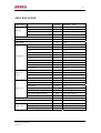
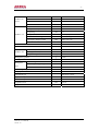
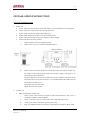
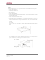
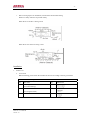
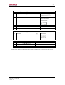
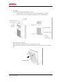
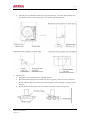
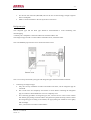
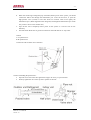
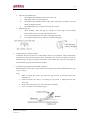
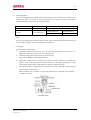
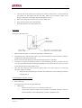
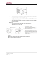
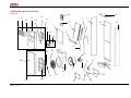
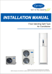
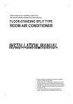
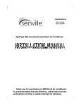
Air Conditional
Service Manual
-2 -
MODEL:
AC-FR50CM
Model No.: AC-FR50CM
Version: 1.0
-3 -
CONTENTS
SPECIFICATION..................................................................................................................................... 4
INSTALLATION INSTRUCTION .......................................................................................................... 6
EXPLODED VIEW AND PART LIST .................................................................................................. 20
CIRCUIT DIAGRAM ............................................................................................................................ 24
Model No.: AC-FR50CM
Version: 1.0
-4 -
SPECIFICATION
Power supply
Ph-V-Hz
Capacity
Cooling
380-240V~, 50Hz
Btu/h
48000
Input
W
5100
Rated current
A
8.6
Btu /w.h
9.4
L /h
4.2
EER
Moisture removal
Max. input consumption
W
6500
Max current
A
12.5
Model
JT160BCBY1L
Type
Scroll
Brand
Daikin
Capacity
Compressor
Btu /h
51180
Input
W
4660
Rated current (RLA)
A
8.6
Locked rotor Amp (LRA)
A
58
Thermal protector
Internal
Capacitor
uF
-
Refrigerant oil
ml
1500
Model
YDK120-8N
Indoor fan
Input
W
341/268
motor
Capacitor
uF
6.5
Speed (hi /mi /lo)
r/min
Number of rows
Indoor coil
580 /480
2
Tube pitch (a) x row pitch (b)
mm
21 x 13.37
Fin spacing
mm
1.4
Fin type (code)
Hydrophilic aluminium
Tube outside dia and type
mm
Φ7, Innergroove tube
Coil length x height x width
mm
422 x 966 x 26.74
Number of circuit
10
Indoor air flow
M3/h
2000
Indoor noise level
dB(A)
48
Indoor unit
Dimension (w x h x d)
mm
540 x 1775 x 279
Packing (w x h x d)
mm
665 x 1915 x 475
Net /Gross weight
Kg
66 /71
Model No.: AC-FR50CM
Version: 1.0
-5 -
Model
YDK250-6D
Outdoor fan
Input
W
307 / 292 / 290
motor
Capacitor
uF
10
r/min
740
Speed
Number of rows
Outdoor coil
2
Tube pitch x row pitch
mm
25.4 x 22
Fin spacing
mm
1.7
Fin type (code)
Non-hydrophilic aluminium
Tube outside dia and type
mm
Φ9.53, Innergroove tube
Coil length x height x width
mm
890 x 914 x 44
Number of circuits
2
Outdoor air flow
M3/h
5000
Outdoor noise level
dB(A)
55
Outdoor unit
Dimension (w x h x d)
mm
990 x 960 x 360
Packing (w x h x d)
mm
1120 x 1090 x 435
Net /gross weight
Kg
90 /105
Refrigerant type R22
Design pressure
Refrigerant
pipe
g
MPa
Liquid side /gas side
Mm (inch)
1650
2.6
Φ12.7 / Φ19
Max. refrigerant pipe length
m
15
Max. difference in level
m
5
Connecting wiring
No
Plug type
No
Thermostat type
Electronic control
Operation temp
oC
17-30
Ambient temp
oC
18-45
Application area
M2
40~56
Qty per 20’ & 40’ Fcl
Model No.: AC-FR50CM
Version: 1.0
Pieces
25 /48 /60
-6 -
INSTALLATION INSTRUCTION
Selection installation place
1.
Indoor unit
a.
A place which provides the spaces around the indoor unit as required above in the diagram.
b.
A place where is no obstacle near the inlet and outlet area.
c.
A place which can bear the weight of the indoor unit.
d.
A place which allows the air filter to be removed downward.
e.
A place where the reception range is not exposed to direct sunlight.
f.
In the center the room where possible.
i.
Please stand the unit in hard and flat ground.
ii.
Please reserve space for installation and maintenance.
iii.
Please check the elevation difference between the indoor unit and the outdoor unit,
the length of the refrigerant pipe and the curved places (bend) of the pipe are no
more than the following number.
Elevation difference: No more than 10M (if the elevation difference between indoor
and outdoor unit is more than 10 meters, it is recommended that the outdoor unit be
placed above the indoor unit.)
Pipe length: No more than 20M
Bends: No more than 5 places
2.
Outdoor unit
a.
Before installing the outdoor unit,
i.
Select a place where no direct sunlight or other heat-radioactivity may reach. A
sunshade is needed if it is unavoidable.
ii.
Select a place that is easy to connect indoor unit’s pipe and electric wires.
iii.
Avoid a place where combustible gas may leak or stay.
iv.
Keep it in mind that water may drain out of the outdoor unit while in “Heat” mode.
Model No.: AC-FR50CM
Version: 1.0
-7 -
Caution
Installation in the following places may cause trouble. If it is unavoidable to use in such places:
A place full of machine oil.
A saline place such as coast.
Hot-spring resort.
A place full of sulfide gas.
A place where there are high frequency machines such as wireless installation, welding
machine, medical facility.
A place of special environmental condition.
b.
If the outdoor unit is to be installed on a roof or where no constructions are around, you
should avoid hard wind blows directly to the outlet because it may cause trouble for air-flow
shortage.
For example:
Let the air outlet face a wall (if there is one) with a distance about 300 centimeters between
them.
Try to make the air outlet vertical to wind direction if it is known in the season you use the
system. In directions A, B, C leave open two of the three directions.
Model No.: AC-FR50CM
Version: 1.0
-8 -
c.
Reserve enough space for installation, maintenance and unit-functioning.
Remove as many obstacles as possible nearby.
When the air-in surface is facing a wall.
When the air out surface is facing a wall.
Installation
1.
Indoor Unit
a.
Accessories
Before installing, please check the available accessories according to the list given below.
Accessories for installing
No
Part name
Qty
1
Installing board
1
(for wall mounting)
2
3.9 x 25 screw
2
(for fixing the board)
3
Plain washer
Model No.: AC-FR50CM
Version: 1.0
4
Illustrations
-9 -
Accessories for pipe-connecting
No
Part name
Qty
4
Pip-hole-protection ring
1
5
Sound /heat insulation sleeves
2
Illustrations
Outer Diam: 52mm
Inner Diam: 36mm
Length: 100cm
6
Water receiver
1
7
Seal
1
8
Drain joint
1
Accessories for wire-connecting
No
Part name
Qty
9
Sleeves for wire-connecting
2
10
Band
3
Illustrations
Refrigerant pipe (optional)
No
Name
11
12
capacity (Btu/h)
20000~30000
30000~55000
Liquid side size
Diam: 9.53mm
Diam: 12.7mm
Gas side size
Diam: 16mm
Diam: 19mm
If there is any difference between the above table and packing list, the packing list shall prevail.
Model No.: AC-FR50CM
Version: 1.0
-10 -
b.
Anti-falling
To prevent the indoor unit from falling, you must:-
c.
i.
Pay full attention to the unit because its long outer shape makes it easy to fall.
ii.
Firmly fix the unit to the wall and in the ground to avoid accidental falling.
Dismounting the air-inlet grid
Please take off the air-inlet grid before connecting the pipes /wires.
Pull down the two knobs on the grid, take off the two screws, then the air-inlet grid goes
free.
Model No.: AC-FR50CM
Version: 1.0
-11 -
d.
Take the pipe clip off before connecting the pipes and wiring. Fit it when these finished. Use
accessories 4 and 9 to connect the pipes /wires on both sides and back side.
2.
Outdoor Unit
a.
Ship the a/c to the installation place originally packed.
b.
Be careful while hanging the unit because the center of gravity of the unit is not centralized.
c.
Do not make the angle of inclination more than 45 degrees while shipping. (Avoid horizontal
storage).
d.
Be sure the electric insulation work is well done if installed on metal ceiling /wall.
Model No.: AC-FR50CM
Version: 1.0
-12 -
e.
Fix the unit feet with bolts (M10/M8). Be sure the unit is fixed strongly enough to against
blast or earthquake.
f.
Make a concrete basement to the unit by the above references.
Refrigerant pipe
The refrigerant pipe and the drain pipe should be heat-insulated to avoid condensing and
water-dropping.
A reamer joint is adopted to connect the indoor unit with the outdoor unit.
The refrigerant pipe is used to connect indoor and outdoor units, showed as below.
Note: The bendable pipe must not be curved for more than 3 times.
Note: Cover all exposed reamer joint pipes and refrigerant pipes with heat-insulation material.
1.
Connecting of refrigerant pipe
a.
Only the correctly installation of indoor and outdoor unit done, can the refrigerant pipe be
connected.
b.
The cut-off valves are completely close before ex-work. Before connecting the refrigerant
pipe, be careful to check whether the valve are completely close.
c.
The connecting procedure of refrigerant pipe; first, unscrew the two valves on the outdoor
unit and the pipe-jointing nut on the indoor unit (please keep them care fully). Please connect
the refrigerant pipe according to the manual, the pipe-jointing nut should be screw tightly
and no leakage.
Note: you need two wrenches to make balance.
Model No.: AC-FR50CM
Version: 1.0
-13 -
d.
When the connecting of refrigerant pipe is finished, before power on the system, you should
vacuum the indoor unit through the maintenance port in the cut-off valves, or open the
high-pressure valve (closed). It will take about ten seconds. Then screw tightly the
maintenance port. (When supplement the refrigerant, fill thought the maintenance port of the
low-pressure valves on the outdoor unit).
e.
Open all the valves completely before power on the system or it will be sick for low
f.
Gas leak check. Make sure no gas from connections with leak detector or soap water.
efficiency.
Caution
A: Lo packed valve
B: Hi packed valve
C and D are ends of indoor unit connection.
Caution in handling the packed valve
Open the valve stem until it hits against the stopper. Do not try to open it further.
Securely tighten the valve stem cap with a spanner or the link.
Model No.: AC-FR50CM
Version: 1.0
-14 -
Notes for the bendable pipe
i.
The bendable pipe should be used on the indoor side.
ii.
Bend angel may not exceed 90 degrees.
iii.
The bend location should be made on the center of the pipe if possible, as for bend
radius, the bigger the better.
iv.
The bendable pipe may not be bent for more than 3 times.
Bend the thin pipe
i.
While bending, expose the pipe by cutting the concave gap on the bending
heat-insulation pipe (roll it with soft band after bent).
2.
ii.
To avoid pipe deformation, the radius is the bigger the better.
iii.
Use a pipe-bending device to make the compact bending pipe.
Using bronze pipe selling in market
Completely shut the cut-off valves of the outdoor unit (as ex-work status). After the refrigerant
pipe has been connected with both the indoor and outdoor unit, let the air exhaust out from the
maintenance gap on the low-pressure cut-off valve of the outdoor unit. Screw the nuts tightly on
the maintenance gap after the air has been drained.
3.
To make the refrigerant pipe unblocked completely.
Should keep the cut-off valves of the outdoor unit completely open after finished the above steps
(step 1 or step 2).
Note:
Before screwing the reamer nut, smear the pipe and the connecting surface with
refrigerant oil.
Check and make sure there is no leakage by soap-water or leakage-checker after
connecting.
Be sure the connecting joint on the in door side is insulated.
Use two wrenches to connecting the pipe.
Model No.: AC-FR50CM
Version: 1.0
-15 -
4.
Filling refrigerant.
The correct refrigerant quality filled in the 5-meter-long pipe of the outdoor unit is marked on the
Product Data Plate. If you have to use longer pipe for every meter plus pipe, the refrigerant
should be added according to the following calculation.
Connective pipe length
Air purging method
Additional amount of refrigerant to be charged
Less than 5m
Use vacuum pump
-
5~20m
Use vacuum pump
Liquid side Φ 9.53
Liquid side Φ12.7
(L-5) x 65g
(L-5) x 90g
Note:
If you are using pipe purchased in the market, please make sure the heat-insulation material is the
same as what we supply. (At least 12 millimeters in thickness).
5.
Air purging
When using the vacuum pump
a.
Completely tighten the flare nuts A, B, C, D connect the manifold valve charge hose to a
charge port of the low-pressure valve on the gas pipe side.
b.
Connect the charge hose connection to the vacuum pump.
c.
Fully open the handle Lo of the manifold valve.
d.
Operate the vacuum pump to evacuate. After starting evacuation, slightly loose the flare nut
of the Lo valve on the gas pipe side and check that the air is entering. (operation noise of the
vacuum pump charges and a compound meter indicates 0 instead of minus).
e.
After the evacuation is complete, fully close the handle Lo of the manifold valve and stop the
operation of the vacuum pump.
Make evacuation for 15 minutes or more and check that the compound meter indicates –
76cmHg (-10x106Pa).
Model No.: AC-FR50CM
Version: 1.0
-16 -
f.
Turn the stem of the packed valve B about 45o counter clockwise for 6~7 seconds after the
gas coming out, then tighten the flare nut again. Make sure the pressure display in the
pressure indicator is a little higher than the atmosphere pressure.
g.
Remove the charge hose from the Low pressure charge hose.
h.
Fully open the packed valve stems B and A.
i.
Securely tighten the cap of the packed valve.
Drain pipe
Drain pipe of the indoor unit
1.
Make sure the drain pipe is connected to the outdoor side downward.
2.
The hard polyvinyl chloride (PVC) plastic pipe (external diameter 26 mm) sold is the market is
suitable for the attached soft drain pipe.
3.
Please connect the Soft Drain Pipe with the Drain Pipe, then fix it with band.
4.
If you have to connect the Drain Pipe indoors to avoid condensing caused by air intake, you must
cover the pipe with heat-insulation material (polyethylene with specific Gravity of 0.03, at least 9
mm in thickness) and use glue band to fix it.
5.
After the Drain Pipe has been connected, please check if the water drains out of the pipe
efficiently and has no leakage.
Refrigerant Pipe and Drain Pipe should be heat-insulated to avoid condensing and water
dropping later on.
Connecting the electric system
1.
Wire connecting
The outdoor unit will look one of the following:
a.
Outdoor unit
i.
Remove the electric parts cover from the outdoor unit.
ii.
Connect the connective cables to the terminals as identified with their respective
matched numbers on the terminal block of indoor and outdoor units.
Model No.: AC-FR50CM
Version: 1.0
-17 -
iii.
To prevent the ingress of water, form a loop of the connective cable as illustrated in
the installation diagram of indoor and outdoor units.
iv.
Wiring connection must be done strictly according to the “Wiring Diagram” located
on the panel of air conditioner.
v.
Follow the instruction of wiring connection in this manual, never attempt to modify
the wiring by yourself.
b.
Outdoor unit
i.
Unscrew the maintenance board. Pull it down as the signal shown.
(Be careful not to scratch the crust.)
Caution
Wrong wiring connections may cause some electrical parts to malfunction.
The air conditioner must be grounded well.
Model No.: AC-FR50CM
Version: 1.0
-18 -
2.
Wire-connecting brief diagram (for details refer to wire-connecting diagram)
Note:
i.
Some models is equipped with a cord having a plug. So a wall outlet shall be properly
installed.
ii.
Please remember the surroundings (environmental temperature, direct sunlight, rain etc.)
iii.
We consider the minimal size of the metal core as the wire size. So it is recommended you
adopt a thicker one as the power conducting wire so as the wire size. So it is recommended
you adopt a thicker one as the power conducting wire so as to avoid power decrease.
iv.
Connect the grounded wire to both indoor and outdoor units.
v.
This table is just an on-site wire-connecting example.
The length of the power wire and connecting-wire which connects the indoor unit to the
outdoor unit. (The figure given below shows a suitable length).
Model No.: AC-FR50CM
Version: 1.0
-19 -
3.
Electrical safety check
Perform the electric safe check after completing installation:
a.
Insulated resistance
The insulated resistance must be more than 2M Ω.
b.
Grounding work
After finishing grounding work, measure the grounding resistance by visual detection and
grounding resistance tester. Make sure the grounding resistance is less than 4Ω.
c.
Electrical leakage check (performing during test running)
During test operation after finishing installation, use the electroprobe and multimeter to
perform the electrical leakage check. Turn off the unit immediately if leakage happens.
Check and find out the solution ways till the unit operate properly.
Test run
Perform test operation after completing gas leak and electrical safety check. The test operation time
should last more than 30 minutes.
1.
Open the panel and lift the panel up to angle which remains fixed. Do not lift the panel any
further when it stops with a “click” sound.
2.
Press the manual switch button twice until the operation indicator lights, the unit will operate on
Manual Cool mode.
3.
Check if all the functions works well while testing the air conditioner. Especially check whether
the drainage of indoor unit is smooth or not.
4.
Press the manual switch button again till the operation indicator turns dark after finishing the test
operation and the unit stops operation.
Model No.: AC-FR50CM
Version: 1.0
-20 -
EXPLODED VIEW & PART LIST
30
Indoor unit
1
1.1
1.2
1.3
1.5
1.4
10
1.6
9
7
31
3
11
12
5
2
2.1
4
2.2
8
6
26
29
22
28.2
17
15
16
23
13
24
27
28
Model No.: AC-FR50CM
Version: 1.0
25
18
28.1
21
20
19
14
-21 -
Part list for indoor unit
No
1
1.1
1.2
1.3
1.4
1.5
1.6
2
2.1
2.2
3
4
5
6
7
8
9
10
11
12
13
14
15
16
17
18
19
20
21
22
23
24
25
26
27
28
28.1
28.2
29
30
31
32
33
Part name
Air out frame assy
Horizontal louver
Horizontal louver holder
Front panel
Holder for louver motor
Vertical louver
Louver motor
Display box, assy
Display box cover
Display box assy
Front cover
Water collector assy
Evaporator I
Evaporator II
Outlet pipe for evaporator
Inlet pipe for evaporator
Evaporator temp sensor
Left cover
Top cover
Rear cover
Right cover
Chassis
E-Parts box
Main control board
Fan motor capacitor
Transformer
Wire joint 4p
Wire joint 5p
Wire clamp
E-part box cover
Fan motor
Centrifugal fan
Volute shell
Wind inlet guide
Indoor temp sensor
Formaldehyde cleaner
Grille assy
Air filter
Grille
Air cleaner holder
Holder for remote controller
Remote controller
Copper nut, TLM-E05
Copper nut, TLM-C03
Model No.: AC-FR50CM
Version: 1.0
Qty
1
6
1
1
1
5
1
1
1
1
1
1
1
1
1
1
1
1
1
1
1
1
1
1
1
1
1
1
1
1
1
1
1
1
1
1
1
1
1
1
1
1
1
1
-22 -
Outdoor Unit
10
13
11
14
12
9
8
15
7
16
6
1
2
3
4
17
5
18
20
19
21
22
32
33
29
23
27
24
25
26
31
Model No.: AC-FR50CM
Version: 1.0
30
28
-23 -
Part list for Outdoor unit
No
1
2
3
4
5
6
7
8
9
10
11
12
13
14
15
16
17
18
19
20
21
22
23
24
25
26
27
28
29
30
31
32
33
34
35
Part name
Clamp for front net
Front net
Front clapboard
Propeller fan
Fan motor
Holder for fan motor
Chassis
Separating board
Cover
Small handle
Condenser
Support board for motor holder
Left supporting bar
Rear net
Rear right clapboard
Big handle
Installation plate for valves
Water collector
Fan motor capacitor
Installation board for E-parts
AC contactor
Main control board
Wire joint for multiplexer
Wire joint
Washer for wire joint
Wire clamp
Liquid valve assy
Liquid valve
Gas valve assy
Gas valve
Compressor
Discharge temp sensor
Front right clapboard
Copper nut, TLM-C03
Copper nut, TLM-E05
Model No.: AC-FR50CM
Version: 1.0
Qty
10
2
1
1
1
1
1
1
1
1
1
1
1
1
1
1
1
1
1
1
1
1
1
1
1
1
1
1
1
1
1
1
1
1
1
-24 -
CIRCUIT DIAGRAM
OUTDOOR UNIT
Model No.: AC-FR50CM
Version: 1.0
-25 -
INDOOR UNIT
Model No.: AC-FR50CM
Version: 1.0