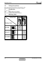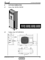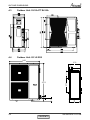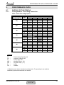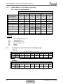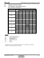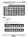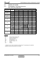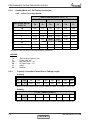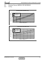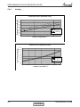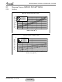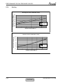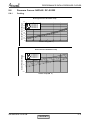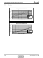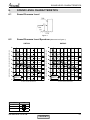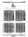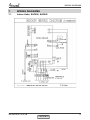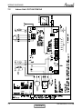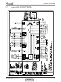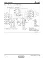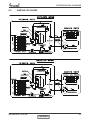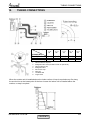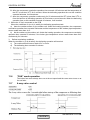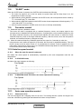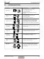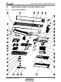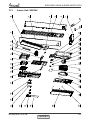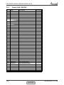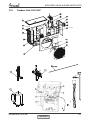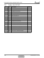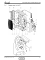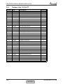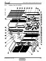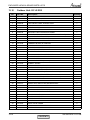
1
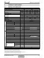
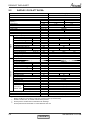
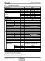
SAF Fixed RPM Series Indoor Units SAF024 SAF045 Outdoor Units OU7-24Z OU10-47T GC 45 REFRIGERANT COOLING ONLY R22 HEAT PUMP R410A SM SAFRPM 1-A.0 GB AUGUST 2009 CONTENTS LIST OF EFFECTIVE PAGES LIST OF EFFECTIVE PAGES Note: Changes in the pages are indicated by a “Revision#” in the footer of each effected page (when none indicates no changes in the relevant page). All pages in the following list represent effected/ non effected pages divided by chapters. Dates of issue for original and changed pages are: Original ....... 0 ........ March 2009 Total number of pages in this publication is 53 consisting of the following: Page No. Revision No. # Title ........................... A................................ i ................................. 1-1 - 1-2 .................... 2-1 - 2-3 .................... 3-1............................. 4-1 - 4-2 .................... 5-1 - 5-12 .................. 6-1 - 6-2 .................... 7-1 - 7-5 .................... 8-1............................. 9-1............................. 10-1 .......................... 11-8 ........................... 12-1........................... 13-10......................... 14-1........................... • Page No. Revision No. # Page No. Revision No. # 0 0 0 0 0 0 0 0 0 0 0 0 0 0 0 0 0 Zero in this column indicates an original page. *Due to constant improvements please note that the data on this service manual can be modified with out notice. **Photos are not contractual. A SM SAFRPM 1-A.0 GB CONTENTS TABLE OF CONTENTS Table of Contents 1. INTRODUCTION ...................................................................................................1-1 2. PRODUCT DATA SHEET ......................................................................................2-1 3. RATING CONDITIONS ..........................................................................................3-1 4. OUTLINE DIMENSIONS .......................................................................................4-1 5. PERFORMANCE DATA & PRESSURE CURVES ................................................5-1 6. SOUND LEVEL CHARACTERISTICS ..................................................................6-1 7. WIRING DIAGRAMS .............................................................................................7-1 8. ELECTRICAL DATA ..............................................................................................8-1 9. REFRIGERATION DIAGRAMS .............................................................................9-1 10. TUBING CONNECTIONS......................................................................................10-1 11. CONTROL SYSTEM .............................................................................................11-1 12. TROUBLESHOOTING ..........................................................................................12-1 13. EXPLODED VIEWS AND SPARE PARTS LISTS .................................................13-1 14. APPENDIX A .........................................................................................................14-1 SM SAFRPM 1-A.0 GB i INTRODUCTION 1. INTRODUCTION 1.1 General The floor-standing air conditioner of SAF fixed RPM series has some strongpoint, such as modern outlook, excellent quality, amazing price. It comprise RC, RH, models, as follows: • SAF024 R410A • SAF045 R410A • SAF045 R22 1.2 Main Features The SAF Fixed RPM series benefits from the most advanced technological innovations, namely: • LCD display • Ionizer as an option • Auxiliary PTC heater as an option. • Automatic vertical louver • Pre-charged system up to 10m for model 24 R410A • Pre-charged system up to 15m for model 45 R410A • Up to 50 Meter tubing length (in model 45) R22 • Scroll compressor (in model 45) • Compact size of outdoor units. • Easy installation and service. 1.3 Indoor Unit The indoor unit is floor-standing type indoor unit, and can be easily fitted to many types of residential and commercials applications as restaurant, shops, reception room etc. It includes: • Coil with hydrophilic aluminum fins. • Motorized air flap. • Low sound level of the indoor fan 1.4 Control The microprocessor indoor controller, and an infrared remote control, supplied as standard, provide complete operating function and programming. For further details please refer to the Owner’s Manual, Appendix A. 1.5 Outdoor Unit The outdoor units can be installed as floor or wall mounted units by using a wall supporting bracket. The metal sheets are protected by anti- corrosion paint work allowing long life resistance. All outdoor units are pre-charged. For further information please refer to the Product Data Sheet. It includes : • Compressor mounted in a soundproofed compartment . • Axial fan. • Outdoor coil with hydrophilic louver fins for RC units. • Outlet air fan grill. • Service valves” flare” type connection. • Interconnecting wiring terminal block. SM SAFRPM 1-A.0 GB 1-1 CONTENTS INTRODUCTION 1.6 Tubing Connections Flare type interconnecting tubing to be produced on site. For further details please refer to the Owner’s Manual. 1.7 Accessories Remote Control 1.8 Inbox Documentation Each unit is supplied with its Owner’s Manual. 1.9 Matching Table Indoor Unit SAF024 SAF045 Outdoor Unit OU7-24Z OU10-47T GC 45 R22 SM SAFRPM 1-A.0 GB 1-2 CONTENTS PRODUCT DATA SHEET 2. PRODUCT DATA SHEET 2.1 SAF024 / OU7-24Z R410A Model Indoor Unit Model Outdoor Unit Installation Method of Pipe Characteristics Capacity Units Btu/hr kW kW W/W (4) Power input (4) EER (Cooling) or COP(Heating) (4) Energy efficiency class Power supply OUTDOOR INDOOR Rated current Power factor Prated (IDU) Prated (IDU+ODU) Starting current Circuit breaker rating Fan type & quantity Fan speeds H/M/L H/M/L Air flow (1) External static pressure Min H/M/L Sound power level (2) H/M/L Sound pressure level (3) Moisture removal Condenstate drain tube I.D Dimensions WxHxD Net Weight Package dimensions WxHxD Packaged weight Units per pallet Stacking height Refrigerant control Compressor type,model Fan type & quantity Fan speeds H Air flow H Sound power level H H Sound pressure level (3) Dimensions WxHxD Net Weight Package dimensions WxHxD Packaged weight Units per pallet Stacking height Refrigerant type Standard charge Additional charge Liquid line Suction line Connections between Max.tubing length units Max.height difference Operation control type Heating elements (Option) Others Cooling Only 22690 6.65 2.37 2.81 C V Ph Hz A 10.8 0.95 W W A A RPM m3/hr Pa dB(A) dB(A) l/hr mm mm kg mm kg units units RPM m3/hr dB(A) dB(A) mm kg mm kg Units units SAF024 OU7-24Z Flared Cooling 22690 6.65 2.37 2.81 C 220-240 1 50 10.8 0.95 150 3500 66 20 Centrifugal x 1 470/430/380 1000/915/809 0 58/54/52 48/44/42 2.4 25 480x1730x300 36 572x1848x410 45 4 4 levels Capillary tube Rotary Axial x 1 850 3100 Heating 25080 7.35 2.29 3.21 C 10.5 0.95 67 58 In.(mm) In.(mm) m. 900x680x340 78 985x730x435 82 6 2 R410A 2.02kg 4m < Length < 10m: +0g; 10m < Length < 15m: +0g 3/8"(9.53) 5/8"(15.88) Max.15 m. Max.7 kW Remote control 2.1 kg(7.5m) (1) Airflow in ducted units;at nominal external static pressure. Sound power in ducted units is measured at air discharge. (3) Sound pressure level measured at 1-meter distance from unit. (4) Rating conditions in accordance to ISO 5151 and ISO 13253 (for ducted units). (5) The declared value’s tolerance is in accordance with Eurovent. (2) SM SAFRPM 1-A.0 GB 2-1 CONTENTS PRODUCT DATA SHEET 2.2 SAF045 / OU10-47T R410A Model Indoor Unit Model Outdoor Unit Installation method Characteristics Capacity (1) OUTDOOR INDOOR Power input (1) COP (1) Energy efficiency class Power supply Rated current Starting current Circuit breaker rating Fan type & quantity Fan speeds H/ M/ L Air flow (2) H/ M/ L External static pressure Min-Max H/ M/ L Sound power level (3) H/ M/ L Sound pressure level (4) Moisture removal Condensate drain tube I.D Dimensions W/ H / D Weight Package dimensions W/ H / D Packaged weight Units per pallet Stacking height Refrigerant control Compressor type, model Fan type & quantity Fan speeds H/L Air flow H/L Sound power level H/L H/L Sound pressure level (4) Dimensions W/ H / D Weight Package dimensions W/ H / D Packaged weight Units per pallet Stacking height Refrigerant type Refrigerant charges distance Additional charge per 1 meter Liquid line Suction line Connections between units Max. tubing length Max. height difference Operation control type Heating elements Others (1) (2) (3) (4) SAF045(FS) OU10-47T R410A FLARED Units Btu/hr kW kW W/W Cooling 41970 12.30 4.38 2.81 C V/ Ph /Hz A A A RPM m³/hr Pa dB(A) dB(A) L/hr mm mm kg mm kg Units Units RPM m³/hr dB(A) dB(A) mm kg mm kg Units Units kg/m g/m In.(mm) In.(mm) m. m. Heating 47090 13.8 4.37 3.16 D 400/3/50 3x8.6 550 1700 64 54 540 632 900 985 3x8.6 49 3x20A Centrifugal&1 480 380 1500 1188 N/A 62 60 52 50 4.5 25 1776 415 52 1893 535 60 6 2 Capillary Scroll Axial & 2 1220 4500 71 64 970 340 91 1020 435 95 6 2 R 410A 2,3/15 25 3/8”(9.53) 3/4”(19.05) 50 25 LCD Remote Control kW Crankcase heater (50W),3 Phase Protector Rating conditions in accordance to ISO 5151 and ISO 13253 (for ducted units). Airflow in ducted units; at nominal external static pressure. Sound power in ducted units is measured at air discharge. Sound pressure level measured at 1-meter distance from unit. SM SAFRPM 1-A.0 GB 2-2 CONTENTS PRODUCT DATA SHEET 2.3 SAF045 / GC 45 R22 Model Indoor Unit Model Outdoor Unit Installation Method of Pipe Characteristics Capacity Units Btu/hr kW kW W/W (4) Power input (4) EER (Cooling) or COP(Heating) (4) Energy efficiency class V Ph Hz A Power supply OUTDOOR INDOOR Rated current Power factor Prated (IDU) Prated (IDU+ODU) Starting current Circuit breaker rating Fan type & quantity Fan speeds Air flow (1) External static pressure Sound power level (2) Sound pressure level (3) Moisture removal Condenstate drain tube I.D Dimensions Net Weight Package dimensions Packaged weight Units per pallet Stacking height Refrigerant control Compressor type,model Fan type & quantity Fan speeds Air flow Sound power level Sound pressure level (3) Dimensions Net Weight Package dimensions Packaged weight Units per pallet Stacking height Refrigerant type Standard charge W W A A H/M/L H/M/L Min H/M/L H/M/L RPM m3/hr Pa dB(A) dB(A) l/hr mm mm kg mm kg units units WxHxD WxHxD H H H H WxHxD RPM m3/hr dB(A) dB(A) mm kg mm kg Units units WxHxD kg(7.5m) Additional charge Connections between units Operation control type Heating elements (Option) Others Liquid line Suction line Max.tubing length Max.height difference In.(mm) In.(mm) m. SAF045 GC 45 Flared Cooling Only Cooling Heating 43670 43670 52540 12.80 12.80 15.40 4.56 4.56 5.12 2.81 2.81 3.01 C C D 400 3 50 8.1 8.1 9.1 0.85 0.85 0.85 160 6500 65.8 3X20 Centrifugal x 1 550/480/380 1700/1500/1188 0 64/62/60 54/52/50 4.5 25 540x1776x415 52 632x1893x535 60 6 2 levels Capillary tube Scroll,Dakin JT160BCBY1L Propeller(direct)x 2 780 4680 64 56 950x1260x412 120 1100x1300x470 150 1 1 R22 3.1kg 4m < Length < 7.5m: +0g; 7.5m < Length < 25m: +500g; 25m < Length < 38m: +980g; 38m<Length<50m: +1580g; 3/8"(9.53) 3/4"(19.05) Max.50 m. Max.20 kW Remote control 2.1 (1) Airflow in ducted units;at nominal external static pressure. Sound power in ducted units is measured at air discharge. (3) Sound pressure level measured at 1-meter distance from unit. (4) Rating conditions in accordance to ISO 5151 and ISO 13253 (for ducted units). (5) The declared value’s tolerance is in accordance with Eurovent. (2) SM SAFRPM 1-A.0 GB 2-3 CONTENTS RATING CONDITIONS 3. RATING CONDITIONS Standard conditions in accordance with ISO 5151, ISO 13253 (for ducted units) and EN 14511. Cooling: Indoor: 27oC DB 19oC WB Outdoor: 35 oC DB Heating: Indoor: 20oC DB Outdoor: 7oC DB 6oC WB 3.1 Operating Limits R410A Indoor Cooling Heating Voltage Outdoor Upper limit 32oC DB 23oC WB 46oC DB Lower limit 21oC DB 15oC WB 21oC DB Upper limit 27oC DB 24oC DB 18oC WB Lower limit 10oC DB -9oC DB -10oC WB 1PH 198 – 264 V R22 Indoor Cooling Heating Voltage Outdoor Upper limit 32 C DB 23 C WB 46 C DB Lower limit 21oC DB 15oC WB 21oC DB Upper limit 27oC DB 24oC DB 18oC WB Lower limit 10oC DB -5oC DB -6oC WB o 1PH o o 198 – 264 V SM SAFRPM 1-A.0 GB 3-1 CONTENTS OUTLINE DIMENSIONS 4. OUTLINE DIMENSIONS 4.1 Indoor Unit: SAF024, SAF045 C Model SAF024 SAF045 A 485 mm 545 mm B 300 mm 420 mm C 1730 mm 1780 mm A B 4.2 Outdoor Unit: OU7-24Z R410A SM SAFRPM 1-A.0 GB 4-1 CONTENTS OUTLINE DIMENSIONS 4.3 Outdoor Unit: OU10-47T R410A 4.4 Outdoor Unit: GC 45 R22 950 187.5 81 80.8 378 340 112.5 65.4 572 1270 SM SAFRPM 1-A.0 GB 4-2 CONTENTS PERFORMANCE DATA & PRESSURE CURVES 5. PERFORMANCE DATA 5.1 SAF024 / OU7-24 Z R410A 5.1.1 Cooling Mode at 7.5m Tubing Connection. 230V : Indoor Fan at High Speed. ENTERING AIR DB OD Coil(oC) 15 20 (1) (1) 25 30 35 40 46 ENTERING AIR WB/DB ID Coil(oC) 15/21 17/24 19/27 21/29 23/32 Data TC SC PI TC SC PI TC SC PI TC SC PI TC SC PI TC SC PI TC SC PI 7.01 4.88 7.26 5.09 7.43 5.28 7.61 5.42 7.72 5.52 1.68 1.68 1.69 1.69 1.70 6.78 4.78 7.15 5.04 7.37 5.25 7.55 5.40 7.71 5.50 1.82 1.83 1.84 1.85 1.85 6.42 4.66 6.93 4.94 7.28 5.21 7.50 5.36 7.69 5.46 1.97 1.99 2.00 2.01 2.03 6.00 4.51 6.53 4.79 7.06 5.10 7.31 5.25 7.53 5.35 2.13 2.16 2.18 2.19 2.21 5.56 6.03 6.65 6.98 7.31 4.29 4.60 4.98 5.12 5.22 2.29 2.33 2.37 2.39 2.40 5.05 4.04 5.50 4.35 6.00 4.71 6.56 4.86 6.90 4.96 2.47 2.51 2.56 2.59 2.61 4.38 3.72 2.70 4.79 3.99 2.74 5.27 4.30 2.81 5.82 4.45 2.85 6.27 4.54 2.88 LEGEND TC SC PI WB DB ID OD – – – – – – – Total Cooling Capacity, kW Sensible Capacity, kW Power Input, kW Wet Bulb Temp., (oC) Dry Bulb Temp., (oC) Indoor Outdoor (1) Marked area is below standard operating limits. For operating in low ambient conditions, Optional Accessories are needed. SM SAFRPM 1-A.0 GB 5-1 CONTENTS PERFORMANCE DATA & PRESSURE CURVES 5.1.2 Heating Mode at 7.5m Tubing Connection. 230V : Indoor Fan at High Speed. ENTERING AIR DB ID COIL(Oc) 15 20 25 ENTERING WB OD COIL(oC) TH Pl TH Pl TH Pl -10 3.86 1.83 3.71 1.95 3.56 2.05 -7 4.15 1.88 4.01 1.98 3.86 2.09 -2 4.41 1.90 4.26 2.02 4.12 2.13 2 5.37 1.99 5.15 2.12 4.92 2.24 6 7.57 2.14 7.35 2.29 7.09 2.43 10 8.23 2.26 8.01 2.42 7.79 2.58 15 8.89 2.36 8.67 2.54 8.45 2.70 20 9.37 2.43 9.15 2.63 8.89 2.84 LEGEND TH PI WB DB ID OD 5.1.3 – – – – – – Total Heating Capacity, kW Power Input, kW Wet Bulb Temp., (oC) Dry Bulb Temp., (oC) Indoor Outdoor Capacity Correction Factor Due to Tubing Length Cooling TOTAL TUBING LENGTH 3m 7.5m 10m 15m 20m 25m 30m 40m 50m 1.02 1 0.981 0.966 --- --- --- --- --- * Minimum recommended tubing length between indoor and outdoor units is 3m. Heating TOTAL TUBING LENGTH 3m 7.5m 10m 15m 20m 25m 30m 40m 50m 1.05 1 0.99 0.983 --- --- --- --- --- * Minimum recommended tubing length between indoor and outdoor units is 3m. SM SAFRPM 1-A.0 GB 5-2 CONTENTS PERFORMANCE DATA & PRESSURE CURVES 5.2 SAF045 / OU10-47T R410A 5.2.1 Cooling Mode at 7.5m Tubing Connection. 230V : Indoor Fan at High Speed. ENTERING AIR DB OD Coil(oC) 15 20 (1) (1) 25 30 35 40 46 ENTERING AIR WB/DB ID Coil(oC) 15/21 17/24 19/27 21/29 23/32 Data TC SC PI TC SC PI TC SC PI TC SC PI TC SC PI TC SC PI TC SC PI 12.96 9.22 13.43 9.61 13.74 9.98 14.07 10.23 14.28 10.42 3.11 3.11 3.12 3.12 3.14 12.54 9.03 13.22 9.52 13.64 9.92 13.96 10.21 14.26 10.39 3.37 3.38 3.39 3.41 3.42 11.87 8.80 12.81 9.34 13.47 9.85 13.88 10.13 14.22 10.32 3.64 3.67 3.69 3.72 3.74 11.10 8.52 12.08 9.06 13.05 9.63 13.52 9.91 13.92 10.10 3.93 3.99 4.02 4.05 4.09 10.28 11.15 12.30 12.92 13.53 8.10 8.69 9.41 9.68 9.87 4.24 4.31 4.38 4.41 4.44 9.34 7.64 10.17 8.22 11.10 8.90 12.14 9.18 12.76 9.37 4.57 4.64 4.72 4.78 4.83 8.11 7.04 5.00 8.86 7.54 5.07 9.75 8.12 5.19 10.77 8.40 5.26 11.60 8.59 5.32 LEGEND TC SC PI WB DB ID OD – – – – – – – Total Cooling Capacity, kW Sensible Capacity, kW Power Input, kW Wet Bulb Temp., (oC) Dry Bulb Temp., (oC) Indoor Outdoor (1) Marked area is below standard operating limits. For operating in low ambient conditions, Optional Accessories are needed. SM SAFRPM 1-A.0 GB 5-3 CONTENTS PERFORMANCE DATA & PRESSURE CURVES 5.2.2 Heating Mode at 7.5m Tubing Connection. 230V : Indoor Fan at High Speed. ENTERING AIR DB ID COIL(Oc) 15 20 25 ENTERING WB OD COIL(oC) TH Pl TH Pl TH Pl -10 7.25 3.50 6.97 3.72 6.69 3.91 -7 7.80 3.58 7.52 3.78 7.25 3.99 -2 8.28 3.63 8.00 3.85 7.73 4.06 2 10.07 3.80 9.66 4.04 9.25 4.28 6 14.21 4.09 13.80 4.37 13.32 4.64 10 15.46 4.31 15.04 4.61 14.63 4.93 15 16.70 4.50 16.28 4.85 15.87 5.16 20 17.60 4.63 17.18 5.03 16.70 5.42 * the above chat includes the weighted deicing infleuence. LEGEND TH PI WB DB ID OD 5.2.3 – – – – – – Total Heating Capacity, kW Power Input, kW Wet Bulb Temp., (oC) Dry Bulb Temp., (oC) Indoor Outdoor Capacity Correction Factor Due to Tubing Length Cooling TOTAL TUBING LENGTH 3m 7.5m 10m 15m 20m 25m 30m 40m 50m 1.02 1 0.98 0.97 0.96 0.95 0.93 0.92 0.91 * Minimum recommended tubing length between indoor and outdoor units is 3m. Heating TOTAL TUBING LENGTH 3m 7.5m 10m 15m 20m 25m 30m 40m 50m 1.03 1 0.99 0.97 0.95 0.94 0.93 0.92 0.92 * Minimum recommended tubing length between indoor and outdoor units is 3m. SM SAFRPM 1-A.0 GB 5-4 CONTENTS PERFORMANCE DATA & PRESSURE CURVES 5.3 SAF045 / GC 45 R22 5.3.1 Cooling Mode at 7.5m Tubing Connection. 230V : Indoor Fan at High Speed. Entering Air DB OD Coil (oC) 15 (1) (1) 20 25 30 35 40 46 Data Entering Air WB/DB ID Coil (oC) 15/21 17/24 19/27 21/29 23/32 TC 13.49 13.97 14.30 14.64 14.86 SC 9.55 9.96 10.34 10.60 10.80 PI 3.23 3.24 3.25 3.25 3.27 TC 13.05 13.76 14.19 14.53 14.84 SC 9.36 9.87 10.28 10.57 10.77 PI 3.51 3.52 3.53 3.55 3.56 TC 12.35 13.33 14.02 14.44 14.80 SC 9.12 9.67 10.20 10.50 10.69 PI 3.79 3.82 3.85 3.87 3.90 TC 11.55 12.58 13.59 14.07 14.49 SC 8.83 9.39 9.98 10.27 10.47 PI 4.09 4.15 4.19 4.22 4.26 TC 10.69 11.60 12.80 13.44 14.08 SC 8.40 9.00 9.75 10.03 10.23 PI 4.41 4.49 4.56 4.59 4.62 TC 9.72 10.59 11.55 12.63 13.28 SC 7.92 8.52 9.22 9.52 9.71 PI 4.76 4.83 4.92 4.98 5.03 TC 8.44 9.22 10.14 11.21 12.08 SC 7.29 7.81 8.41 8.70 8.90 PI 5.20 5.28 5.40 5.48 5.54 LEGEND TC SC PI WB DB ID OD – – – – – – – Total Cooling Capacity, kW Sensible Capacity, kW Power Input, kW Wet Bulb Temp., (oC) Dry Bulb Temp., (oC) Indoor Outdoor (1) Marked area is below standard operating limits. For operating in low ambient conditions, Optional Accessories are needed. SM SAFRPM 1-A.0 GB 5-5 CONTENTS PERFORMANCE DATA & PRESSURE CURVES 5.3.2 Heating Mode at 7.5m Tubing Connection. 230V : Indoor Fan at High Speed. ENTERING AIR DB ID COIL)O C) 15 20 25 ENTERING WB OD COIL)o C) TH Pl TH Pl TH Pl -10 8.09 4.10 7.78 4.36 7.47 4.58 -7 8.70 4.20 8.39 4.43 8.09 4.67 -2 9.24 4.25 8.93 4.51 8.62 4.76 2 11.24 4.45 10.78 4.74 10.32 5.02 6 15.86 4.79 15.40 5.12 14.86 5.44 10 17.25 5.05 16.79 5.40 16.32 5.78 15 18.63 5.27 18.17 5.68 17.71 6.04 20 19.64 5.43 19.17 5.89 18.63 6.35 * the above chat includes the weighted deicing infleuence. LEGEND TH PI WB DB ID OD 5.3.3 – – – – – – Total Heating Capacity, kW Power Input, kW Wet Bulb Temp., (oC) Dry Bulb Temp., (oC) Indoor Outdoor Capacity Correction Factor Due to Tubing Length Cooling TOTAL TUBING LENGTH 3m 7.5m 10m 15m 20m 25m 30m 40m 50m 1.01 1 0.97 0.96 0.94 0.93 0.9 0.85 0.81 * Minimum recommended tubing length between indoor and outdoor units is 3m. Heating TOTAL TUBING LENGTH 3m 7.5m 10m 15m 20m 25m 30m 40m 50m 1.02 1 0.99 0.98 0.97 0.97 0.95 0.93 0.92 * Minimum recommended tubing length between indoor and outdoor units is 3m. SM SAFRPM 1-A.0 GB 5-6 CONTENTS PERFORMANCE DATA & PRESSURE CURVES 5.4 Pressure Curves: SAF024 / OU7-24 Z R410A 5.4.1 Cooling. Discharge Pressure (Bar[g]) Discharge Pressure VS.Outdoor Temp 40 38 36 34 32 30 28 26 24 22 20 18 16 :%'%|& :%'%|& :%'%|& :%'%|& :%'%|& 15 20 25 30 35 Outdoor Temp.(DB oC ) 40 46 40 46 Suction Pressure VS.Outdoor Temp Suction Pressure (Bar[g]) 12.0 :%'%|& :%'%|& :%'%|& :%'%|& :%'%|& 11.0 10.0 9.0 8.0 7.0 6.0 15 20 25 30 35 Outdoor Temp.(DB oC ) SM SAFRPM 1-A.0 GB 5-7 CONTENTS PERFORMANCE DATA & PRESSURE CURVES 5.4.2 Heating. Discharge Pressure(Bar[g]) Discharge Pressure VS.Outdoor Temp 40 38 36 34 32 30 28 26 24 22 20 18 16 '%|& '%|& '%|& -10 -5 0 5 10 Outdoor Temp.( WB oC ) 15 20 Suction Pressure VS.Outdoor Temp Suction Pressure(Bar[g]) 11.0 10.0 9.0 8.0 7.0 '%|& '%|& '%|& 6.0 5.0 4.0 3.0 -10 -5 0 5 10 Outdoor Temp.( WB oC ) 15 20 SM SAFRPM 1-A.0 GB 5-8 CONTENTS PERFORMANCE DATA & PRESSURE CURVES 5.5 Pressure Curves: SAF045 / OU10-47T R410A 5.5.1 Cooling. Discharge Pressure (Bar[g]) Discharge Pressure VS.Outdoor Temp 40 38 36 34 32 30 28 26 24 22 20 18 16 :%'%|& :%'%|& :%'%|& :%'%|& :%'%|& 15 20 25 30 35 Outdoor Temp.(DB oC ) 40 46 40 46 Suction Pressure VS.Outdoor Temp Suction Pressure (Bar[g]) 12.0 :%'%|& :%'%|& :%'%|& :%'%|& :%'%|& 11.0 10.0 9.0 8.0 7.0 6.0 15 20 25 30 35 Outdoor Temp.(DB oC ) SM SAFRPM 1-A.0 GB 5-9 CONTENTS PERFORMANCE DATA & PRESSURE CURVES 5.5.2 Heating. Discharge Pressure(Bar[g]) Discharge Pressure VS.Outdoor Temp 40 38 36 34 32 30 28 26 24 22 20 18 16 '%|& '%|& '%|& -10 -5 0 5 10 Outdoor Temp.( WB oC ) 15 20 Suction Pressure VS.Outdoor Temp Suction Pressure(Bar[g]) 11.0 10.0 9.0 8.0 7.0 '%|& '%|& '%|& 6.0 5.0 4.0 3.0 -10 -5 0 5 10 Outdoor Temp.( WB oC ) 15 20 SM SAFRPM 1-A.0 GB 5-10 CONTENTS PERFORMANCE DATA & PRESSURE CURVES 5.6 Pressure Curves: SAF045 / GC 45 R22 5.6.1 Cooling. Discharge Pressure VS.Outdoor Temp Discharge Pressure (Bar[g]) 30 :%'%|& :%'%|& :%'%|& :%'%|& :%'%|& 28 26 24 22 20 18 16 14 12 10 8 15 20 25 30 35 40 46 40 46 Outdoor Temp.(DB oC ) Suction Pressure (Bar[g]) Suction Pressure VS.Outdoor Temp :%'%|& :%'%|& :%'%|& :%'%|& :%'%|& 4.5 15 20 25 30 35 3.5 2.5 Outdoor Temp.(DB oC ) SM SAFRPM 1-A.0 GB 5-11 CONTENTS PERFORMANCE DATA & PRESSURE CURVES 5.6.2 Heating. Discharge Pressure VS.Outdoor Temp Discharge Pressure(Bar[g]) 24 22 20 18 '%|& '%|& '%|& 16 14 -10 -5 12 0 5 10 15 20 Outdoor Temp.( WB oC ) Suction Pressure VS.Outdoor Temp Suction Pressure(Bar[g]) 6.0 5.0 4.0 3.0 -10 -5 0 5 10 15 '%|& '%|& '%|& 20 2.0 Outdoor Temp.( WB oC ) SM SAFRPM 1-A.0 GB 5-12 CONTENTS SOUND LEVEL CHARACTERISTICS 6. SOUND LEVEL CHARACTERISTICS 6.1 Sound Pressure Level Figure 1 6.2 Sound Pressure Level Spectrum (Measured as Figure 1) SAF045 -70NC -60NC -50NC -40NC -30NC APPROXIMATE THRESHOLD OF HEARING FOR CONTINUOUS NOISE -20NC MICRO BAR0.002 dB re , OCTAVE BAND SOUND PRESSURE LEVEL MICRO BAR0.002 dB re , OCTAVE BAND SOUND PRESSURE LEVEL SAF024 Hz, BAND CENTER FREQUENCIES FAN SPEED -70NC -60NC -50NC -40NC -30NC APPROXIMATE THRESHOLD OF HEARING FOR CONTINUOUS NOISE -20NC Hz, BAND CENTER FREQUENCIES LINE HI ME LO SM SAFRPM 1-A.0 GB 6-1 CONTENTS SOUND LEVEL CHARACTERISTICS 6.3 Outdoor units Unit 1m Mic. Ground Figure 2 6.4 Sound Pressure Level Spectrum (Measured as Figure 2) OU7-24 Z Heating -70NC -60NC -50NC -40NC -30NC APPROXIMATE THRESHOLD OF HEARING FOR CONTINUOUS NOISE -20NC MICRO BAR0.002 dB re , OCTAVE BAND SOUND PRESSURE LEVEL MICRO BAR0.002 dB re , OCTAVE BAND SOUND PRESSURE LEVEL OU7-24 Z Cooling -70NC -60NC -50NC -40NC -30NC APPROXIMATE THRESHOLD OF HEARING FOR CONTINUOUS NOISE -20NC Hz, BAND CENTER FREQUENCIES Hz, BAND CENTER FREQUENCIES OU10-47T Cooling OU10-47T Heating SM SAFRPM 1-A.0 GB 6-2 CONTENTS WIRING DIAGRAMS 7. WIRING DIAGRAMS 7.1 Indoor Units: SAF024, SAF045 SM SAFRPM 1-A.0 GB 7-1 CONTENTS WIRING DIAGRAMS 7.2 Indoor Unit: OU7-24 Z R410A SM SAFRPM 1-A.0 GB 7-2 CONTENTS WIRING DIAGRAMS 7.3 Indoor Unit: OU10-47T R410A SM SAFRPM 1-A.0 GB 7-3 CONTENTS WIRING DIAGRAMS 7.4 Outdoor Unit: GC 45 R22 SM SAFRPM 1-A.0 GB 7-4 CONTENTS WIRING DIAGRAMS 7.5 Connections between indoor unit and outdoor unit SAF 24 SAF 45 Note: 1. ─ ─ ─ ─ Connection only for heat pump model 2. * Option, Power supply from outdoor or indoor unit SM SAFRPM 1-A.0 GB 7-5 CONTENTS ELECTRICAL DATA 8. ELECTRICAL DATA 8.1 SAF024, SAF045 Note: Power wiring cord should comply with local laws and electrical regulations requirementsl. SM SAFRPM 1-A.0 GB 8-1 CONTENTS REFRIGERATION DIAGRAMS 9. REFRIGERATION DIAGRAMS 9.1 SAF024 / OU7-24Z R410A OUTDOOR UNIT INDOOR UNIT Service port Reverse valve Capillary tube Outdoor coil Sensor Compressor Sensor Strainer Valves Flared connection Capillary tube Indoor coil Check valve Strainer COOLING MODE OUTDOOR UNIT INDOOR UNIT Service port Sensor Compressor Sensor Reverse valve Valves Flared connection Capillary tube Capillary tube Outdoor coil Strainer Indoor coil Check valve Strainer HEATING MODE SM SAFRPM 1-A.0 GB 9-1 CONTENTS REGRIGERATION DIAGRAMS 9.2 SAF045 / OU10-47T R410A SM SAFRPM 1-A.0 GB 9-2 CONTENTS REFRIGERATION DIAGRAMS 9.3 SAF045 / GC 45 R22 SM SAFRPM 1-A.0 GB 9-3 CONTENTS TUBING CONNECTIONS 10. TUBING CONNECTIONS TUBE (Inch) ¼” ⅜” ½” ⅝” ¾” 11-13 13-20 11-13 40-45 13-20 11-13 60-65 18-25 11-13 70-75 18-25 11-13 80-85 40-50 11-13 TORQUE (Nm) Flare Nuts Valve Cap Service Port Cap 1. 2. 3. 4. 5. 6. 7. 8. Valve Protection Cap-end Refrigerant Valve Port (use Allen wrench to open/close) Valve Protection Cap Refrigerant Valve Service Port Cap Flare Nut Unit Back Side Copper Tube When the outdoor unit is installed above the indoor unit an oil trap is required every 5m along the suction line at the lowest point of the riser. Incase the indoor unit is installed above the outdoor, no trap is required. SM SAFRPM 1-A.0 GB 10-1 CONTENTS CONTROL SYSTEM 11. CONTROL SYSTEM 11.1 SAFETY CONTROL 11.1.1 Time delay safety control a. 3 minutes delay for compressor—the compressor is ceased for 3 minutes to balance the pressure in the refrigenration cycle in order to protect the compressor. b. 2 minutes delay for 4-way valve—The 4-way valve is ceased for 2 minutes to prevent the refrigenrant-gas abnormal noise when the HEATING operation is OFF or switch to the other operation mode. 11.1.2 Indoor pipe temperature sensor frost prevention control When the indoor pipe temperature sensor reads 0OCor below for 5 minutes, the indoor pipe temperature sensor frost prevention control starts. The compressor and outdoor fan stop and the indoor fan operates at high speed for 3 minutes. After that, if the indoor pipe temperature sensor reads less than 5OC this control prolonged until the indoor pipe temperature sensor reads 5OC or more. 11.1.3 High temperature protection control During HEATING operation, the outdoor fan motor and compressor are controlled by the indoor pipe temperature to prevent the high temperature of compressor. Outdoor fan OFF: when the indoor pipe temperature is ≥53OC Outdoor fan ON: when the indoor pipe temperature is ≤48OC Compressor OFF: when the indoor pipe temperature is ≥62OC Compressor ON: when the indoor pipe temperature is ≤48OC 11.2 “I Feel” Model Operation 11.2.1 When the “I Feel” mode is selected, the operation mode and initial set temperature are determined by the initial room temperature at startup of the operation except to turn off the air conditioner and operates it again. 11.2.2 If the mode is change to “I Feel” mode form other mode, the “I Feel” mode doesn’t operate until compressor stop for more than 3 minutes In the “I Feel” mode, when the controller receives the up or down single of temperature, the set temperature can adjust by 1OC upper or lower. The biggest you can adjust by 2OC upper or lower. 11.3 “COOLING” Mode Operation 11.3.1 When the COOLING mode is selected without setting temperature, the system will set the set temperature at 26OC automatically with the AUTO FAN speed. 11.3.2 When selecting the COOLING mode operation, the system will operate according to the setting by the remote controller and the operation is as following: SM SAFRPM 1-A.0 GB 11-1 CONTENTS CONTROL SYSTEM 11.4 “DRY” Mode Operation 1.4.1 The system for DRY operation used the same refrigerant circle as the cooling circle. 12.4.2 When the system operates in DRY mode, at first it operates in cooling mode at 16OC or 18OC for 3 minutes. And then, the system operates in cooling mode with low speed that regards the temperature of the room temperature sensor reads decrease 2OC as the set temperature. During the course of this, the fan speed set operation is failing but the vane motor can be controlled. 11.5 “HEATING” Mode Operation (Only available for Heat Pump) 11.5.1 When the HEATING mode is selected without setting temperature, the system will set the temperature at 23OCautomatically with the AUTO FAN speed. 11.5.2 When selecting the HEATING mode operation, the system will operate according to the setting by the remote controller and the operation is as following: 11.5.3 In HEATING mode, the indoor fan motor speed is controlled by Cold Air Prevention Control. 11.5.4 Cold Air Prevention Control a. The function is intend to prevent cold air from being discharged when the heating operation starts or when defrosting. b. The indoor fan speed will be controlled as following. c. The vane angle is at the angle C(100ο) . d. During the heating operation, if the compressor stops that it will adjust the indoor fan speed, after 30 seconds to stop the fan. SM SAFRPM 1-A.0 GB 11-2 CONTENTS CONTROL SYSTEM 11.5.5 Defrost Defrosting of the outdoor heat exchange is controlled by the microprocessor with detection by the indoor pipe temperature sensor. Defrost control type is according to the JC on the PCB whether is connected. 1. When the JC is connect on the PCB When one of the conditions of A, Band C is satisfy, the defrosting operation stars. In the condition A, it must satisfy the condition a),b) and c) then into defrosting operation. a) IPT1 satisfy IPT1=IPTMAX- ΔIPT (8OC) b) t5≥50 minutes (the compressor cumulative operation time ≥50minutes, t5 is permitted move and lower than t1 too). c) IPT <40OC, and keep 2 minutes. According to the condition A enter the defrosting operation, the first defrosting operation time is 8minutes; After defrosting operation one cycle, and then judge and regulate the defrosting operation time. SM SAFRPM 1-A.0 GB 11-3 CONTENTS CONTROL SYSTEM B. After the compressor cumulative operation time exceeds 120 minutes and the temperature of the IPT is less then 35OC for 2 minutes. When the defrosting operation time on this condition exceeds 8minutes, it will terminate. C. After the compressor operation continuously for 20 minutes and the IPT is less than 23OC or from the last time of defrosting operation is 50 minutes or more intervals. When the defrosting operation time on this condition exceeds 10 minutes, it will terminal. 2. When the JC isn’t connected on the PCB When the conditions of a) or b) is satisfy, the defrosting operation starts. a) Have the outdoor sensor on the outdoor unit: Under the heating operation, the compressor cumulative operation time exceeds 50minutes and the temperature of the outdoor pipe temperature sensor reads lower than -4OC b) No the outdoor on the outdoor unit: Under the heating operation, the compressor cumulative operation time exceeds 50 minutes, if the indoor pipe temperature sensor reads lower than 40OC continuously for 2minutes. 3. Defrost terminating conditions When the condition c) or d) is satisfy, the defrosting operation will terminal. c) The outdoor defrost sensor reads 15OC or more. d) The defrosting time exceeds 10 minutes. 11.6 “FAN” mode operation The indoor fan motor always turns on at the set speed and the vane motor turns on at the set fettle. 11.7 4-way valve control SM SAFRPM 1-A.0 GB 11-4 CONTENTS CONTROL SYSTEM 11.8 “SLEEP” mode When the SLEEP button is pressed, the SLEEP mode is selected as following: 1. The indoor fan speed is set at the low speed, the power lamp and the sleep lamp is on, the temperature off after 5 minutes. 2. When selecting COOLING/DRY operation with SLEEP mode, the set temperature will be raised by 1OC 1 hour later and 2OC 2 hour later. 3. When selecting HEATING operation with SLEEP mode, the set temperature will be dropped by 1OC 1 hour later and 2OC 2 hour later. 4. After the system operates in SLEEP mode for 8 hours, it will stop automatically. 11.9 Fan motor control (1) Rotational frequency feedback control The indoor fan motor is equipped with a rotational frequency sensor, and outputs signal to the microprocessor to feedback the rotational frequency. Comparing the current rotational frequency with the target rotational frequency, the microprocessor adjusts fan motor electric to make the current rotational frequency close to the target rotational frequency. With this control, when the fan speed is switched, the rotational frequency changes smoothly. (2) When the rotational frequency feedback signal has not output for 5 seconds (or when the microprocessor can’t detect the signal for 5 seconds), the fan motor is regarded locked-up. Then the electric current to the fan motor is shut off. 10 second later, the electric current is applied to the fan motor again. During the fan motor lock-up, the POWER indicator lamp flashes on and off 6 times/cycle or E6 to show the fan motor abnormality. 11.10 Auto fan speed control 11.10.1 When the auto fan speed is selected, the indoor fan motor speed is automatically controlled by the room temperature and the set temperature. 11.10.2 In COOLING mode, the indoor fan motor operates as following: Fan Speed 11.10.3 In HEATING mode, the indoor fan motor operates as following: Fan Speed 11.11 Auto vane operation control 11.11.1 Vane motor drive The unit is equipped with a stepping motor for the vane. The rotating direction, speed, and angle of the motor are controlled by pulse signal transmitted from indoor microprocessor. SM SAFRPM 1-A.0 GB 11-5 CONTENTS CONTROL SYSTEM 11.11.2 Positioning The vane is once pressed to the cane stopper below to confirm the standard position and then set to the desired angle. The positioning is decided as follows: a. When the ON/OFF button is pressed. b. When the vane control is change from AUTO to MANUAL. c. When the SWING is finished. d. When the test run starts. e. When the power supply turns ON. 11.11.3 The auto vane changes as follows by pressing the VANE CONTROL button. 11.11.4 VANE AUTO mode In vane auto mode, the microprocessor automatically determines the vane angle and operation to make the optimum room-temperature distribution. 11.11.5 SWING mode When presses the SWING button, the vane swings. 11.12 TIMER Operation 11.12.1 To activate the air conditioner at the desire time, follow the procedure specified below(the remote control and air conditioner are switched off): a. Press the TIMER button b. Select the desired mode by pressing the mode button. c. Select the desired temperature by pressing the UP/DOWN button (only possible when the ‘cool’ or ‘heat’ mode is selected). d. Select the ventilator speed (low, medium or high) or automatic mode (only possible when the feel, COOL or HEAT mode is selected) by pressing the Fan button. The ventilator always operates in the auto mode when the dry mode is selected. e. Select swing or no swing by pressing the SWING button f. Press the TIMER button (‘h’ flashes ). g. Use the UP/DOWN button to select the time at which the air conditioner must activate (between 0 and 10 hours can be set at every half hour-between 10 and 24 hours can be set at every hour). h. Press the TIME button (‘h’ stops flashing) and the preset time appears in the display. i. Press the TIME button again to delete the selected data from the memory. Note: if no buttons are pressed during the programming of the timer function, thee remote control will switch off automatically after 10 seconds. 11.12.2 To switch the air conditioner off at the desired time, follow the procedure specified below (the remote control and air conditioner are switched off): a. Press the timer button. b. Use the UP/DOWN button to select the time at witch. 11.13 Emergency Operation When the EMERGENCY operation switch is pressed once, COOLING mode is selected and if in 3 seconds the emergency operation switch is pressed again, mode is selected. Then pressed once again, the unit is switch off. When the remote controller is missing, has failed or the batteries run down, press the EMERGENCY operation switch on the front of the indoor unit. The unit will start. The first 30 minutes of operation will be the test run operation. The operation is for servicing. The indoor fan runs at high speed and the system is in continuous operation. SM SAFRPM 1-A.0 GB 11-6 CONTENTS CONTROL SYSTEM The thermostat is ON and timer is reset to normal. After 30 minutes of test run operation the system shifts to AUTO COOLING/Heating mode, and the indoor fan runs in automatic speed. The operation continues unit the EMERGENCY operation switch is pressed or a button on the remote controller is pressed, the normal operation will start. Note: Do not press the EMERGEMCY operation switch during normal operation. 11.14 AUTO RESTART Function (Option) 11.14.1 When the indoor unit is controlled with the remote controller, the operation mode, set temperature, and the fan speed are memorized by the indoor electric control PCB. The AUTO RESTART function sets to work the moment power has restored after power failure. Then, the unit will restart automatically. 11.14.2 How to set the AUTO RESTART function. a. Press the emergency switch and power supply to the PCB following, keep 10seconds and the buzzer will beep three times. The AUTO-RESTART is set. b. Do the operation again, the buzzer will beep four times and the AUTO-RESTART function is cancelled. 11.15 Electron lock function Press the fan button for 5 seconds, the buzzer beep one sound. The all button is invalidation for operate the air conditioner except the remote controller. 11.16 Failure Display and handling 11.16.1 Failure Display When the controller is failure, the buzzer will voice long for three times, and displays the failure from the failure lamp. 11.16.2 Failure Code If there is the digital pipe that display the failure code for digital pipe, or display for the fun lamp. 12.16.3 Failure Handling a. When the room temperature sensor or the indoor pipe temperature sensor is failure, the system will be shut off, the compressor will be OFF, and the outdoor fan and the indoor fan will be OFF. The system doesn’t receive the signal of remoter controller except the signal of shut off it. When the failure disappeared, the controller can operate in normal mode. Before this, presses the “ON/OFF” to start the system, and it will operate in COOLING or HEATING for 30minutes, and follows shut off. During this, it displays the failure and the protection is failing. You must be given the electric again to operate it. In the failure, you can operate the fan mode. b. When the outdoor protects in the COOLING or DRY, the outdoor unit stops, the indoor fan operates in set speed; and in the HEATING, the outdoor unit stops, the indoor fan operates in cold air prevention control. The system doesn’t receive the signal of remoter controller except the signal of shut off it. When the system check the voltage is 220V and the delay control is finished, it operates at normal again. c. When the indoor fan motor is failure, the compressor is stopped, the outdoor fan and indoor fan is stopped and display the failure. The system doesn’t receive the signal of remoter controller except the signal of shut off it. SM SAFRPM 1-A.0 GB 11-7 CONTENTS CONTROL SYSTEM 11.16.4 Display of the control In the display board the lamp from left is the POWER lamp (Red), the SLEEP lamp (Yellow), the TIMER lamp (Yellow), the RUN lamp (Green) 11.16.5 When gives the control electric, the buzzer voices a long for 0.3 second per cycle. 12.17 Control logic for the heater The control logic for the heater is as follows: Condition to Cut in: If all following conditions are satisfied, the heater can operate: 1. The running time for the compressor exceeds 10 seconds. 2. The normal running time for the IDU Fan exceeds 15 seconds. 3. Not available in deicing mode. 4. Exceed 30 seconds without heater operation. 5. ST-RT≥3OC 6. RT<22OC 7. ICT≤43OC Condition to Cut off If any following condition is satisfied, the heater will be off power: 1. The compressor is power off. 2. RT≥24OC 3. ICT≥48OC 4. The IDU Fan is not running 5. Entering into sleep mode. SM SAFRPM 1-A.0 GB 11-8 CONTENTS TROUBLESHOOTING 12. TROUBLESHOOTING Trouble Analysis If the protector trips or fuse is blown. ? Does not run If the leakage breaker trips. If the plug loosened. Sometimes it stops working to protect the appliance. Is the air filter dirty? Are the intakes and outlets of the air conditioner blocked? Not cool or warm enough Is the temperature set properly? ? Ineffective control Does not operate immediately ? Do not operate If strong interference (from excessive static electricity discharge, power supply voltage abnormality) presents, sometimes operation will be affected. In this case, switch off the breaker and switch on it again 2~3 seconds later. Shifting to other modes during operation, wait 3 minutes to start. Peculiar odor Odor may come from sources such as furniture or cigarette and blown out by the unit. A sound of running-water Caused by the flow of refrigerant inside the air conditioner, not a failure. A"pi-pa" sound can be heard Caused by the expansion or contraction of the internal components due to temperature changes. That is not a failure. Blow mist from the outlet Room air is cooled down by the cold air blown out from the unit and mist thus form during "COOLING" or "DRY" mode when humidity is too high inside. SM SAFRPM 1-A.0 GB 12-1 CONTENTS EXPLODED VIEWS & SPARE PARTS LISTS 13. EXPLODED VIEWS & SPARE PARTS LISTS 13.1 Indoor Unit: SAF024 SM SAFRPM 1-A.0 GB 13-1 CONTENTS EXPLODED VIEWS & SPARE PARTS LISTS 13.2 No. Indoor Unit: SAF024 Items Description Quantity 1 1070710042 Inside Base 1 2 1210520504 Right Plate 1 3 1210710130 Back Plate 1 4 1200710102 Rubber Water Drainage 1 5 1210520503 Left Plate 1 6 1300710366 Evaporator 1 7 1210520113 Top Plate 1 8 1071200043 Pipe Cover 1 9 1090020038 Heater(Option) 1 10 1150520103 Water Drainage 1 11 1150720004 Out Blow Casing Foam 1 12 1150720005 Heat insulation board 1 13 1070520106 Vertical Vane 1 14 1170010008 Synchronization Motor 1 15 1070520530 Horizontal Vane 1 16 1300710361 Up Panel(ARIWELL) 1 16 1300710373 Up Panel(ELECTRA) 1 17 1080520103 Middle Supporter 1 18 1080710302 Heat insulation board Cover 1 19 1090520136 Display PCB 1 20 1070710422 Display PCB Supporter 1 21 1070710014 Display PCB Cover 1 22 1070710424 Spring 1 23 1070710423 Button 1 24 1020710010 Ornamental Board 1 25 1300710364 Down panel 1 26 1070520149 FastEner 1 27 1070520147 Air Filter 1 28 1170230025 Indoor Sensor 1 29 1074060115 Lead Flow Circle 1 30 1080520106 Inside Elactrical Box Cover 1 31 1070010008 Centrifugal Fan 1 32 1170240002 Transformer 1 33 1170050002 Indoor Motor 1 34 1170100056 Fan Motor Capacitor 1 35 1170200079 Terminal 1 36 1090710148 Main PCB(With heater) 1 36 1090710713 Main PCB(Without heater) 1 37 1070520318 Volute Casing 1 38 1080520105 Inside Electrical Box 1 39 1070210005 Anions Generator(Option) 1 40 1090050450 Remote Controller(AIRWELL) 1 40 1090050452 Remote Controller(ELECTRA) 1 SM SAFRPM 1-A.0 GB 13-2 CONTENTS EXPLODED VIEWS & SPARE PARTS LISTS 13.3 Indoor Unit: SAF045 SM SAFRPM 1-A.0 GB 13-3 CONTENTS EXPLODED VIEWS & SPARE PARTS LISTS 13.4 No. Indoor Unit: SAF045 Items Description Quantity 1 1301200262 Inside Base 1 2 1081200126 Right Plate 1 3 1081200103 Back Plate 1 4 1204090101 Rubber Water Drainage 1 5 1081200127 Left Plate 1 6 1110050960 Evaporator 1 7 1301200261 Top Plate 1 8 1071200043 Pipe Cover 1 9 1090020038 Heater(Option) 1 10 1154090101 Water Drainage 1 11 1151200001 Out Blow Casing Foam 1 12 1214090113 Heat insulation board 1 13 1071200014 Vertical Vane 1 14 1170010008 Synchronization Motor 1 15 1071200073 Horizontal Vane 1 16 1301200259 Up Panel(AIRWELL) 1 16 1301200272 Up Panel(ELECTRA) 1 17 1084090101 Middle Supporter 1 18 1090520136 Display PCB 1 19 1070710422 Display PCB Supporter 1 20 1070710416 Display PCB Cover 1 21 1070710424 Spring 1 22 1070710423 Button 1 23 1020710010 Ornamental Board 1 24 1071200069 Down panel 1 25 1070520149 Fastener 1 26 1070300003 Air Filter 1 27 1170230025 Indoor Sensor 1 28 1074090102 Lead Flow Circle 1 29 1084090113 Inside Elactrical Box Cover 1 30 1070010004 Centrifugal Fan 1 31 1170240002 Transformer 1 32 1170030010 Indoor Motor 1 33 1170100057 Fan Motor Capacitor 1 34 1170200079 Terminal 1 35 1090710148 Main PCB (With heater) 1 35 1090710173 Main PCB (Without heater) 1 36 1154090102 Volute Casing 1 37 1084090112 Inside Electrical Box 1 38 1070210005 Anions Generator(Option) 1 39 1090050450 Remote Controller(AIRWELL) 1 39 1090010452 Remote Controller(ELECTRA) 1 SM SAFRPM 1-A.0 GB 13-4 CONTENTS EXPLODED VIEWS & SPARE PARTS LISTS 13.5 Outdoor Unit: OU7-24 Z *Optional 20 18 44 17 24 19a SM SAFRPM 1-A.0 GB 13-5 CONTENTS EXPLODED VIEWS & SPARE PARTS LISTS 13.6 No. Outdoor Unit: OU7-24 Z Item Description Quant 1 437045 LARGE UPPER COVER CUE 1 2 433280 SIDE PANEL OU7-24 R410A 1 3 436357 SMALL ELECTRICAL COVER 1 4 439329 COVERAIR COLLECTOR 1 5 437091 OU SQUARE FAN GUARD 1 6 433722 NEW BASE ASSY OU7-24C EXPORT R410A 1 7 433285 COIL OU7-24 HDR 1 8 4529604 AXIAL FAN D493*143 1 9 434211 REPLACE BY SP000000MOTOR+BRACKET 1 10 433281 SIDE GUADRO OU7-24 R410A 1 11 436358 TRANSPORT HANDLE CUE 1 12 439342 MOTOR SUPPORT OU7 1 14 438795 COMPRESSOR GP270PAA 1 15 433934 CAPILLARY HEATING ASSY OU7-24 R410A 1 16 433660 TUBING ASSY OU7-24Z R410A 1 17 413496 BOARD TPHN 5F (RoHS) 1 18 442007 CAPACITOR 6uF 400V P1/P2 1 19a 434716 THERMISTOR L1050 (for coil) 1 20 442038 CAPACITOR 50mF 400V P1/P2 1 21 437627 COMPRESOR WIRING TPHN-5F 1 24 437229 ELECTRICAL BOX TPHN 1 33 442520 VALVE COIL L700 MOLEX-DUMAN 1 44 192207 CONTACTOR 230V, 40A 1 SM SAFRPM 1-A.0 GB 13-6 CONTENTS EXPLODED VIEWS & SPARE PARTS LISTS 13.7 Outdoor Unit: OU10-47T SM SAFRPM 1-A.0 GB 13-7 CONTENTS EXPLODED VIEWS & SPARE PARTS LISTS 13.8 Outdoor Unit: OU10-47T SP No. Item Description Quantity 1 437045 UPPER COVER EL13 OU LARGE 1 2 417221 Side panel N OU10 1 3 436357 SMALL ELECTRICAL COVER OU 1 4 456714 FRONT PANEL OU10 1 5 439662 GRILLE OU10 2 6 439833 NEW BASE ASSY OU EXPORT 1 7 442712 COIL OU10-47 GR HDR 2R NEW R41 1 8 439650 AXIAL FAN D400*112 (COMMON) 2 9 439651 MOTOR 70W,3S,OU10-50 2 10 417223 Side net panel N OU10 1 11 436358 OU LEADING HANDLE 1 12 439657 MOTOR SUPPORT OU10 1 12b 414226 Motor support flange OU-10 1 12c 414229 Motor support clamp bracket OU 1 13 190443 HEATER CRANKCASE MITSUBISHI CO 1 14 438824 COMPRESSOR ZP54KSE-TFM 1 15 441107 CAPILLARY ASSY OU10-47Z 1 16 438957 Tubing Assembly OU10-47 EXPORT 1 17 438886 BOARD TPHN 3F/3G 1 18 434549 SERVICE VALVE ASSY 3/4F 3 WAY 1 18 442017 CAPACITOR 3mF 450V P1/P2 2 19a 434716 THERMISTOR+CAP WTH CONNECTOR L 1 19b 402741 THERMISTOR WTH CONNECTOR L1250 1 21 445320 COMPRESSOR WIRING WITHOUT PLUG 1 22 402284 SUCTION ACCUMULATOR 5" x 3/4" 1 23 439661 AIR OUTLET RING OU10 2 24 437229 ELECTRICAL BOX TPHN 1 26 436352 RAISING HANDLE OU10 1 28 439656 SIDE COVER OU-8/10 1 31 402165 TYPHOON BOX COVER 1 33 442466 VALVE COIL L700 MOLEX-SANHUA 1 65 416910 CABLE HOLDER 4 SM SAFRPM 1-A.0 GB 13-8 CONTENTS EXPLODED VIEWS & SPARE PARTS LISTS 13.9 Outdoor Unit: GC 45 R22 SM SAFRPM 1-A.0 GB 13-9 CONTENTS EXPLODED VIEWS & SPARE PARTS LISTS 13.10 Outdoor Unit: GC 45 R22 No. Part No. Description Quantity 1 4517832 TOP COVER PAINT ASSY 1 2 4517144 FAN COVER PP+UV/GRILL A 2 3 4520871 BASE PLATE PAINT ASSY. 1 4 4522238 LEFT FRONT PANEL PAINTED ASSY. 1 5 4517834 RIGHT FRONT PANEL PAINT ASSY 1 6 4517772 LITTLE HANDLE 1 7 4521345 DIVIDING PLATE 1 8 4526128 SUPPORT FOR CONTROLLER PANEL 1 9 455000102 DOUBLE PATCH CAPACITOR FOR FAN MOTOR 3UF (CBB61S 2 10 4517782 AC CONTACTOR EB25 OR D2501N 1 11 4517006 TERMINAL BLOCK OF CABLE 1 12 4517308 TERMINAL BLOCK OF POWER SUPPLY 1 13 4517048 TERMINAL BLOCK OF NUETRAL 1 14 4517833 VALVE BASE PAINT ASSY 1 15 4517535 HIGH PRESSURE STOP VALAE 1 16 4517536 LOW PRESSURE STOP VALVE 1 17 4518602 COMPRESSOR CABLE 1 18 467470001 MIX AND MISSING PHASE DEVICE 1 19 4517743 COMPRESSOR ASSY JT160BCBY1L 1 20 4521286 ACCUMULATOR 1 21 4520854 DISCHARGE TUBE1 (12.7*0.7) 1 23 4517783 COMPR. JACKET 1 23 4518782 TOP COVER INSULATION FOR COMP 1 22 4520846 SUCTION TUBE 2 (19.05*1) 1 24 4520863 OIL SEPARATOR WELDING ASSY. 1 25 4520884 CONDENSING TUBE 2(WITH ACCESSORIES) 1 26 4525814 RIGHT-BACK PLATE PAINTED ASSY. 1 27 4519751 PRESSURE SWITCH(3.0MPA OFF/2.4MPA ON) 1 28 4520850 4-WAY VALVE WELDING ASSY. 1 29 4516429 OUT SENSOR BLACK 1 30 4521113 SINGLE-WAY AND FILTER WELDING ASSY. 1 31 C66037900 CONDENSER ASSY/LOWER/GC48 1 32 C65063600 MANIFOLD WELDING ASSY 1 33 4517576 CONDENSOR ASSEMBLY (UP) 1 34 4524731 BACK GRILLE PAINT ASSY 1 35 4525909 CONNECT PANEL ASSY 1 36 4517767 COMPR. SUB HEATER 1 38 4519199 MOTOR KICKSTAND 1 39 4517740R MOTOR YYK60B-6 2 40 4517004 AXIAL FAN D=450MM 2 41 4523141 HEXAGON LOCKED NUT M10 2 42 C66038000 DISTRIBUTING CAPILLARY ASSY 1 SM SAFRPM 1-A.0 GB 13-10 CONTENTS APPENDIX A APPENDIX A INSTALLATION AND OPERATION MANUAL ► INSTALLATION & OPERATION MANUAL SAF024 ► INSTALLATION & OPERATION MANUAL SAF045 SM SAFRPM 1-A.0 GB 14-1 CONTENTS