1
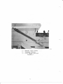
AGIRA/ELY
PROFESSIONAL A-WHEEL
TRACTORS (G SERIES)
OPERATOR'S MANUAL
FORM NO:42639 (11-86)
PART NO: 41853, 41871, 41876
41966, 41974,42149
PRINTED IN USA
NOTE
Read this manual carefull-y
your tractor before using it.
and
learn to operate and service
To keep the warranty, the tractor must be maintained
operated as directed in this manual.
references to nleft-siden, nright-siden,
nbackn are given f rom the operatorts positj.on.
All
nfrontn,
and
and
Use the serial numbers to ensure prompt and correct service
when ordering parts, requesting service r ot making inquiries.
TRACTOR
ENGINE
SERIAL
SERIAL
NUMBER
NUMBER
ENGINE SPEC NUI,IBER
Look for this symbol to point out important safety
precautions. It meAns -- ATTENTION! BECOII,IE ALERT!
YOUR SAFETY IS INVOLVED.
CONTENTS
1.
INSTRUCTIONS FOR SAFE OPERATION
2.
CONTROLS
3.
OPERATING INSTRUCTIONS
4.
SERVICE INSTRUCTIONS
5.
STORAGE
6.
PROBLEM SOLVING
.I
SPECIFICATIONS AND WIRING
.
8.
SET-UP INSTRUCTIONS
9.
WARRANTY
SECTION
1
Instructions for Safe Operation
rmproper use of this tractor can injure people and damage the
equipment. People using or servicing this Lractor must reid and
follow the instructions in this manual.
It is irnportant to understand that this manual and any other
Gravely instruction manuals do not cover every possible danger.
It is impossible for Gravely to know of all possiUfe dangeri in
<lperating and servicing the tractor and attachments.
The purchaser must give these instructions to the people operating and niaintaining this tractor. These people musl use eya and
foot protection.
1"1
Preparation
1. Read the tract.cr
caref ulJ-y.
1
3.
4.
K
6.
Learn the -ocat -on
atLachment c*ntrols Learn how ru
atr-achment.
use
ancj atL.achment operatorrs
and function of
all
manuais
tractor
ihc control-s to stop the t ract.or
and
anci
Use caution with gasoline" Gasol-ine is very flammable.
Keep it in a clran and tight container away frorn fJ,arnes
or hot items. Never put gasol:ne in the fuel tank whii-e
the engine is running or hot. C1ean up spilled gasoline
before startlng engine,
Be certain that ait shields, guards, and interl-ock
switches are in the correct positions.
when hauling the tractor, connect the chassis and rear
hitch to the transporting vehicle. Never connect from
control Ievers, rods 1 or like items that couLd be
damaged.
L.2 Operation
1. wear foot and eye protection.
Do not wear loose
clothing.
2. Do not use the tractor in the dark without adequate
1 ighting.
3, Keep the tractor in good condition. Maintain it as
directed in this manual.
4. Replace all parts that becorne damaged or }ost.
5. USE ONLY GRAVELY ACCESSORIES AND ATTACHMENTS OR ATTACHI'IENTS GRAVELY HAS APPROVED FOR USE WITH THIS TRACTOR.
6. Do not overspeed the engine.
governor.
Do not override the
7. Keep away from moving parls.
8. Keep people and animals away from the operating area.
9" Do not let people other than the operator ride on the
suJ-ky.
10, Use a slow speed and engage the direction control lever
slowly when operating on slopes.
11. Look for and keep away from hazards.
12. Before starting nNEUTRAL"
the engine, put the direction control
position and the PTO control in
lever,OFF"
in the
position.
the
13. Look behind when operating in reverse.
1"4. After hitting an object with the tracLor or attachment,
stop the engine and check for damage. Repair any damage
before continuing operation.
15. Operate the tractor only fron the operatorrs position,
on the seat.
16. Travel up and down slopes.
I7 . Never permit children to operate the tractor.
18. Before
leaving the tractor, move the PTO control to
nOFFn, lock the brake or put in gear and engage
the
direction control leverr and remove the ignition key.
19. rf there is a sudden change in the sound or vibration of
the tractor or attachmeits, stop the
check
for damage. Repair any 'damagl
"rrfirr"-ino
or
fairure
before
continuing operation.
20. Never ryn the engine indoors except to move it outside.
Exhaust fumes are dangerous.
2I. Go slow on slick surfaces.
22. Follow traffic raws when operating on or near a road.
23. Before making_ adjustments or servicing, move the PTO to
rOFFnf turn the ignition switch to noFF;,
and wait until
all moving parts completely stop.
SECTION
2
Controls
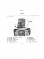
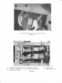
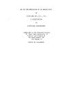
2.I Figures 1 and
the controls.
I
2
3
4
5
6
7
2
show the locations and
Direction Control
Lever
8
9-
Brake Pedal
Brake Lock Lever
Gear Selector
Range Selector
PTO Control
Hydraulic Lift, Control
FIGURE
10
11
L2
13
1
identifications of
Ammeter
Hourmeter
Choke Control
Fuse Holder
Throttl-e Control
Ignition
Switch
I Manual Lift Lever
2
Release Button
3- Lift Range Control
FIGURE
5
2
SECTION
3
Operating Instructions
Read the
Read this manuaL before operating the tractor.
Operator's Manual- for any attachment that is to be used.
From the tractor seat, note the location of the tractor and
(See Section 2.) ALWAYS BE IN THE SEAL
attachment controls.
WHEN OPERATING THE TRACTOR OTHER THAN IN STATIONARY APPLICATIONS.
3.1 Before Starting the Engine
Be sure that the tractor and engine has
serviced and maintained.
been properly
3.2 Starting and Stopping the Engine
To start the engine:
1. The direction control lever must be in 'NEUTRAL'
position and the PTO control must be at 'OFF" position.
2. Put the key in the ignition switch.
3. l"love the throttle lever to a middle position.
4. If the engine is cold, move the choke lever
to nONn. If
rrOFFn.
it is warm, the choke lever should be at
When the eng ine
5. Turn the ignition key to " START'' .
starts, move the choke lever s1ow1y to "oFF". rf the
engine does not start in five seconds, release the key
for a few seconds and then repeat. If the engine does
not start within five tries,
see Section 6 for
instructions.
CAUTION: Do not keep the starter running for over 15
seconds. Do not run the startet for more
than 15 seconds in any one minute.
To stop the engine:
1. Move the throttle lever to I'SLOW'.
2. Turn the ignition switch to nOFFn.
3. Remove the key before l-eaving the tractor.
3.3 Operating the Transmission
Do Nor sHrFT TRANsMrssroN GEARS wHrLE THE FoRwARD
[ceurron, OR
REVERSE CLUTCHES ARE ENGAGED OR THE TRACTOR IS
MOVING. This will damage the gears. Always place
the direction control lever in 'NEUTRALn and bring
the tractor to a complete stop before moving the
gear or range selectors.
3.3.1 To Move in a Forward Direction
Use slow engine and transmission speeds until you know how
to operate the tractor safely.
1. start the engine and move the throttle to give the
desired engine speed.
2. Fut the range and gear sel-ectors in the positions that
will produce Lhe desired speeds. See Section 7 for
gnound speeds produced.
3. Move the direction control lever forward. As the
tractor increases speed, push the lever untir it. locks
into position. ff; the lever is not pushed all the way
forwandr slippage can damage the f,orward clutch. USE
CAUTION WHILE I,EARNING TO OPERATE TTIE DIRECTION
CONTROL I,EVER.
NOTE:
The operator must be in Lhe seat to operat.e the
direction control lever. If the operator leaves the
seat
with the ili rection control- lever in the
nFORWARDn position, the
engine will- stop,
3.3,2 To Move in a Reverse oirection
1. FolLow Steps 1 throuEh 3 under 3.3.1 above.
2. Pull the direction control lever firnly backward. The
controL lever does not lock into a reverse position.
You must continue lo pull back firmly to continue
reverse travel.
It will return to rNEUTRALr upon
release.
3.3,3 Stopping the Tractor
Pushing the brake pedal down will stop the tractor and
return the direction control- lever to nNEUTRALn. Use the
brake pedal for sudden stops and for holding the tractor
on slopes.
3.3.4 Locking the Brake
To lock the brake for parking, depress the brake pedal and
pull back on the brake lock Jever. To reJease, push on
the pedal and move the lock lever forward.
3.3.5 Using the PTO
To power an attachment, push the PTO control forward to
'ONn. To stop n.an attachmenL, pulI the pTO controL
rearward to "OFF
The operator must be in the tractor
seat to operate the PTO. If the operator leaves the seat
while the PTO control is in the nON[ position, the engine
wili stop.
3.3.6 Correct Operating
Speeds
On rough and sloping ground and when mowing and
trimming near buildings, trees, and other
obstructionsl us€ d slow ground speed.
Ivlost attachments, especially rotary mowers and
snowblowers perform best when operated at full
engine speed. Proper ground speed is determined by
power limitations, the type of terrain, the quality
requirements of
the job being performed,
obstructions, hazards, etc.
[wanurnc,
NOTE:
3.4 Using the Attachment Lift Systems
Manual or hydraulic lift systems are used to raise and lower
attachments. Either can hold an attachment in position or
let it folIow the ground.
3.4.I Using the Manual Lift
System
To hold an attachment in position:
I. Lift the attachment to the raise position.
2. Lift the lift
range cont rol and slide it
desired position.
8
to the
3, Lower the attachment. The Iift lever will stop
against the lift range controL. ff the attachment is
not in the desired position, repeat Steps I and 2.
To let an attachment follow the ground:
1. Move the lift range control to the lowest position.
2. Lower the attachment to the ground.
3.4.2 Using the Hydraulic Lift. System
To hold an attachment in position:
I. Lift the attachnent by pulling back on the hydraulic
lift Jever until the attachment is fully raised.
2. Lower the attachment to the desired position by gently
pushing the lift lever forward.
3. When the attachment reaches the desired position,
release the lever.
The attachment will be held in
that position.
To 1et an attachment follow the ground:
1. PushI'FLOATn
the hydraulic lift lever all the way forward to
position. The attachment will be lowered
the
to the ground and the lever wil] remain at that
position until you pul1 it backwards.
3.5
Using the Tractor
for Stationary
Operations
To operate an attachment, such as a compost shredder that
uses PTO power when the tractor is stationary:
1. Move the tractor attachment to the desired location.
Put a weight in the seat.
2. Lock the brake and block wheels.
3. Put the gear selector in 'liEUTRALn.
4. Move the PTO control to nON'.
5. Use caution when leaving the tractor seat. Keep away
from moving parts.
I
SECTION
4
Service Instructions
Chart I
shows
performed on
a
the recommended schedule for service that should
regular basis.
SERVICE
Chcc3.- Batt-ery.-
PERFORI\,IED
Fluid
(sect
ion
Shqs&ilaLgsx's---iAesui,ss"- ,*51'--
4 .5
)
I
I
TrtlE
|
L
TNTERVALS
BETWEEN SERVICE
I
L
tii
-_L-*L.**--*"!*=Xrll
t
*
.
(;he=k*;hfu--I-n-takc* -r5-cLses**L$-e"sLt-4.{r-9"-i_L-*-.*--*'1-.".-"*&**L.*-_--ehee&"*Ci: o-}j ns-S&*sLem.lgc-atj:an*
trl
4-*S-i**-_-**+-----*-:*l**-e-"r-.- *
ill
eheekMiqn*€""*3i
Ctreeil--Es-ansiei$s:i=-an-
Check Ti
re
oi-t*[Ss$ti-E:r*
4
^
.*J*8"1-."---l-*
ttl
J**-e
LL) -.*-i
tl
Filling the Fuel-
-i.
*"-
,"
tlxl
Sressur e -l5es-Li-aa"J-1**CIIART
4.I
be
1
Tanls
is very flammable. Follow saf ety
$rwo*Nt^c, Gasoline
instructions shown in Section 1.
Use clean lead free or
Gasoline is added as required.
gasoline:
regular grade gasoline. To add
I. Put the tractor in an open area.
2, Stop the engine and lock the brake.
3. Clean the fuel cap area.
4. Remove the fuel tank cap.
Use caution. Do not
5. FiII the tank with gasoline.
overflow
"
" Rcir:sLail- f uel. ';ank cap"
7 * If qanoJ-ini: is sg>iltredr wipe i:
6
i0
up"
4.2
General Lubrication
There are seven grease fittings to be greased at 25-hour
intervals.
Clean the fittings before attaching the grease
gun.
Use a multi-purpose grease. Add grease until it
appears at the ends of the bearings. The locati ons of the
seven fittings are:
1. On the direction control lever.
2. On the front axle at each king pin.
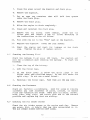
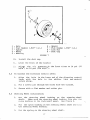
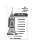
3. On the front axle as shown in Figure 3.
4. On the steering mechanism as shown in Figure 4.
Appty motor oi1 to all pin connections, pivot points and
areas where slid ing occurs in the clutch, transmission, PTO,
and I ift control systems every 25 hours.
4.3 Checking the Engine Oi1
Check the eng ine oil leve1 daily . Never operate t 1,e' eng ine
with the oi1 leveI below the Jow niark on the di6;stick. See
y our eng ine nranual for oil
spec if ications and oil f ilter
service instructions.
To check the oil level:
1. Clean around the dipstick to prevent dirt fron, entering
the tube.
Remove the dipstick and wipe off the oil.
3, Put the dipstick back in p1ace. Be sure it js all the
way down.
4.
5.
6.
4.4
the dipstick again and note oil level.
Add oil, if needed. Do not overfill.
Repeat Step 3.
Remove
ine Oil
Read your eng ine rnanual f or r ecornmended change scheduf e.
Move the tractor to a 1evel area. Lock the brake.
If the engine is cold, fet it run f or 5 nrinutes.
When the eng ine is warm, stop it and r a.ise the rear
Chang
1.
2.
3.
4.
ing the
Eng
fender.
VIARNlNG:
Fngine rnuffler and other parts are hot.
11
I -
Grease
Fitting on the Front AxIe
FIGURE
1- Grease Fittings for the Steering
2- Grease Fittings for lhe Steering
3- Adjusting Bolt
3
Arms
Columns
FIGURE 4
12
4
5
Lock Nut
Adjusting
Nut
5. Clean the areas around the dipstick and drain plug"
6. Remove the dipstick.
7. Put an open top container that will hold four quarts
under the drain plug.
B. Remove the drain p1ug.
9. Allow the engine to drain completely.
i0, Clean and reinstall the drain plug"
(some nodels), clean the cil
11. Remove the oil tilter
filter port and install a new cil filter according to
the instructions on the oil filter.
\2. F' ill with new oil- to the "FULL" mark on t.he d ipstick.
13. Replace the dipstick. Lower the rear fender.
-.:-4" Start the engine and check f,or ieakage a.t the Crain
FIug , Tighten the plug if leakaoe occurs.
4,5 Checking the BaLtery Fiu:c
Check the battery f 1u j.d every 200 hours " Use caution and
wear eye prot.ection when check ing the baLtery. To check tLre
battery:
i"" Clean the top of the "hattetry.
2" Lift the f itrler cap$"
3, If the fl"uid level is below the split rinEs in the
f i1ler tube, ddd d i still-ed water . Do not f i11 above tiLe
spl it r ing . Do not use a metal f unnel- .
4. Reinstall the filler caps. Push them all the way down.
4,6 Checking the Fasteners
Look f or ioose or missing
Check all- f asteners l,er iooically.
fasteners any time looseness of parts, rattles, or excess
noise and vibration are noted. Make sure all bolts, screws,
nuts, pins, snap rings, and cotter pins are in the correct
position and replace any that are missing.
4.7 Checking the Air fntake Screen
Check the air intake screen on the engine each day. Remove
any grass, dirt, or debris that may have accumul-ated on it.
THE
AIR INTAKE
SCREEN IUUST
BE KEPT CLEAN.
13
4"8 CheckinE the Cooling Systern
Check the cooJ- inE systern f c'r signs c'f tire collection of
grass and debris in ttre engine cooling f,ins every 25 hours
or more often when operated in dirty conditions. See your
engine nanua,l for irrstructions'
4"9
Checking the Air Cleaner
Ctreck the air cleaner each day.
insi:ructions.
See
your engine manual fot
4.10 Changing the Air Cleaner Element
Replace the air cleaner el-er,ent at the correct intervals '
5ee your eng ine rnanual- f or instructions.
4.11 Checking the Transmission Oil
Check the transmission oil leve1 every 25 hours. If leakage
j s observed, check nrotre frequently .
The f i11 tube and
To
check the transmission
check plug are shown in Figure 5.
oil Jevel:
1. Move the tractor to a 1evel area. Stop the engine and
lock the brake.
2. Raise the rear fender.
3. Clean the check plug and remove it.
4. The oil level is correct when oil is at the bottom of
the hole.
5. If the level is correct, reinstall and tighten the plug.
See Section 7 for
If the level is low, add oil.
recommended lubr icant specif ications.
To add oi1:
l. Remove the fill tube cap.
2. Add oit until it reaches the bottom of the check plug
ho1e.
3. Reinstall and tighten the fitl
14
tube cap and check plug.
86025
1 - FilI Tube
2 - Check Plug
FIGURE
5
4.I2 Servicing the Brake
Brake service is required if the brake does not stop and
hold the tractor effectively. The brake should be effective
enough to cause the rear wheels to slide it applied suddenly
on a concrete or asphalt surface.
the brake banci when the lining' is as thin
[ceurron, Replace
as the ignition key.
Replace the brake drum if it is visibly worn or
rough.
To adjust the brake;
1. Stop the tractor on a level surface.
2. Stop the engine and block the wheels so the tractor
cannot roll.
3. Loosen the jam nut and remove the clevis pin.
15
4.
5.
Turn the clevis clockwise to tighten or counterclockwise
to loosen as needed.
To check the adjustnent, reconnect the clevis and brake
band with the pin.
6.
Push the direction control- Iever a1l the way forward.
7.
Push the brake pedal by hand while watching the motion
of the brake band. The brake is correctly adjusted when
8.
the band becornes tight on the drun as the direction
control l-ever rnoves to nNEUTRALT'. If the band is tight
before the lever noves to nNEUTRALn, the brake is too
tight. If Loo t.ight or too loose, repeat Steps 4t 5,6,
and 7 until the correct adjustment is obtained.
Install the cotter pin in the cl-evis pin and tighten the
9.
Check the effectiveness of the brake while operating the
jain nut.
tractor.
4.13 Servicing the Forward and Reverse Clutches
The forward and reverse clutches nust be checked every 100
hours. If the lining has worn to a thickness of less than
0.150 inch (3.8mm), replace the lining, The forward clutch
is on the right side of the transnission and the reverse
clutch
is on the left side of the transrnission. See Figure
tr
Inspect and adjust the clutches as follows:
1. Stop the engine and place the direction control lever in
the'TNEUTRALn position.
2. Raise the rear fender.
3. Ivleasure the clearance in the slot.
The correct
clearance is .030 inch (.76mn) to .060 inch (1.5nn).
4. Adjust the bolts which go through the flange on the axle
bearing retainer so that the forward-reverse clutch
springs are straight up and down when the clutches have
zero clearance. Lock the bolt in place with the jan
nut.
Loosen the jan nut which holds the slide rod
bushing in p1ace. Adjust the bushing on the slide rod
until the clearance is correct.
Lock the bushing in
place with the jarn nut.
5. Lubricate the clutch once each season. Remove the
clutch and apply a filn of rnul-ti-purpose grease to the
splined clutch shaft. While the clutch is off, check
the lining wear. rf the lining has worn near the rivet
heads, replace the lining.
Re-adjust the cl_utch as
described above.
It)
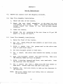
4"14 $ervicing the PTO Clutch
The PTO clutch should be adjusted whenever there j,s less
than .5 inches of f ree tnavel in the cl-utehr lever when it is
in the 'ONu position. See Fi-gure 6 to see where this free
travel- is neasured " The f ree travel- shoul-d be beti+eerr " 5
inch and I.CI inch. To adjust:
1". SLop the engine and lock the brake.
2" troosen the bolts holding the switch bracket and push the
bracket down,
3. Raise the rear fender.
4"
trush the PTO lever to UON'.
c
Disconnect t-he PTO control f rom the transmiss j on I ever "
Turn the control- rod to change the free travel. Each
turn wj-11 change it by about .25 inch. Turn clockwise
to increase and countercioc:kwjse to decrease the free
6.
travel,.
7"
Reconnect the control rod to the transmission I ever
8.
Check for correct free travel.
if necessary.
.
Repeat Steps 4, 5, and
6
Put the PTO control in the "OFF" position.
10. Move the switch bracket up until the sw itch closes
(makes a circuit).
11. Tighten the switch bracket hardware.
Irlake sure that the PTO control assembly does not
[Noru:
rest on the switch bodY.
o
-\
q
oru C-
FIGURE
17
6
4.l-5
ing the Steer i ng Sy stem
Adjustment is usually needed whenever there is more than 2
j-nches of free play in the steering wheels. To adjust the
steer ing gear:
1. Loosen the lock nuts on both adjusting bolts.
See
Figure 4.
2. Turn the steering wheel to the r ight as f ar as it wil,]
Serv ic
go.
4.
Turn the adjusting nut on the left side adjusting bolt
clockwise with your fingers until it is tight.
Then
back the nut off one fourth turn.
Tighten the lock nut against the adjusting nut beii:q
careful not to move the adjusting nut.
Turn t-he steering wheel bo the.l-eft as far as r,t:rii1
\.jJ'
6
F.epeat,
Steps 4 and 5 for t?ie righL side adji:gr.ir,r,,
-,.^t,
Check for tightnessj at L;a,cklash in thc, stee-.r:r::ct r.i{ts..r
thrcugh the full- range of the steerinE wheel rc;t.at j,,;,::.
There shoul-d be no nr:ticeable tiEhtness or back l-all: ti
the rack and pinion mesh, Jf t"he::e is, ;eper:t $tepi; ir
tbrough 7 as required.
of the steering gear adjustment.n rech*ck the
steering wheel free play.
If the free play is st;ill
excessive, look for loose steering arms on the king piirs,
l-oose or worn ball j oints, o!: other signs of wear " Tight,en
or: replace as required.
Upon cornpletion
4.16 Servicing the Spark Plug (s)
To clean or change a spark plug:
1. Stop the engine, lock the brake, and raise the rear
fender.
2.
See
your engine manual for further j-nstructions.
4.I7 Hydraulic Lift Service:
Check the hydraul, ic f lu id level when:
:l-. The hydraulic l.ifL will not raise the attachment.
2. Leaks are observed.
1B
To check the hydraufic fluid level:
1; Put the hydraul ic I ift control 1n the "FLOAT" (ftill
forward) position.
2. C1ean the area around the filter/reservoir.
3. Remove the filter/reservoj.r.
I\'iOTE: When the filter is
removed, some oil will run out because of the l-or,;
pressure valve in the filter.
Oil spillage wi1l, be
minimized if the fil-ter is rernoved after the tractor has
not been operated for one-half hour.
4. The correct hydraulic ftuid level is one inch from the
Add Dextron 1I ATF to maintain this
top of the filter.
l-evel-.
The fiLter/reservoir
shoul-d be replaced when:
1. The tractor has been used one year commerci.ally.
2. The tractor has been used 2 years by a consurrer.
3" The hydraulic system has been repaired.
To install- a new fLlter/reservoir:
1. F'ill a new filter to one inch from the top (observe the
threaded hole).
2. Let the filter
set for 15 minutes. Refill- the filter to
the correct level-.
3. Install the filter.
4. If the hydraulic system has been repaired or leaks fluid:
a. Operate the 1ift.
b. Shut off the tractor.
c. Put the hydraulic lif t control in the 'TFLOATil
pos it ion .
d. Remove the fLLLer/reservoir and fill to one inctr
below the top.
e. Replace the filter/reservoir.
4.18
Adjustment of Range Selec tor
1. Move the Hi-Lo shift lever as far as it wiII go both
d irections.
Measure the distance between the Iever and
the end of the slot. This distance should not be Iess
than 5/16".
2. Adjust the clevis so that the clearance between the Hi-Lo
shift Iever and the control cover plate slot is equal for
both positions of the lever.
19
SECTION
5
Storage
5.1 When the tractor
not be operated for more than
two
1. Do the daily and 25-hour maintenance, but do not
add
months:
will
gasoline.
2. Clean the t.ractor. Paint or oil bare metal surfaces to
prevent rust.
3, Refer to the engine manual and prepare the engine for
storage.
4. Clean and charge the battery. Charge the battery every
three or four weeks whiLe in storage,
5, Place the P.T.O. lever in 'OUT* position.
5. Store in a cool, dry place.
5.2 To use the tractor again:
1. Refer to the engine manual and prepare the engine for
service.
2. Charge the battery.
3. PuL freshr clean gasoLine in the fuel tank.
20
SECTION
6
Problem Solving
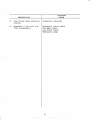
OBSERVATION
.
1" No sound or motion when
is
the ignition switch
TTSTARTU
the
to
turned
position.
I
I
POSSIBLE
CAUSE
control in the UON' Position
Direction Control Lever in the
forward or reverse Position
PTO
Blown fuse
Discharged battery
Starting solenoid damaged
Dama.ged tine rlelaY moduie
Loose battery cable(s)
lre:!: r- jror j"i.; ;r $. t i" Or: iw i b.C l:
,ris t: i.trilc:d to uoST'AR.T", thre
t:',1 ,:)rq.ri"l:i "c1i"oJk,so* an'J +-tre
i:rrg5:.ie sL{-JrLer nict()r cloes
rfib, c'p4:abe"
Fisetiarqed battery
i3atter:y ca"b'1e connector iB)
iiie Jgni tiotl switch
j.s, turned to'sSTAF.Tr', the
Relay or relay connection{s}
Fuel tank empty
Fuel valve turned cff
Engine spark plug(s) fouleo
see Engine
Engine failure
Service Manual
Regulator-rectif ier f ailure
Fuse holder or batterY
Engine alternator failure
Battery failure
Ground wire not connected
Ignition swi tch failure
id
iiiifi.,)r,
:star- Le':; ope!:ates but the
crii;i.r"le' does not start.
4. tsett€ry d ischarged
r
ine continues to run
when the ignition switch
is rotated to the rrOFFrr
position.
6.
Lights do not come on
switch is
when the 1i9htrroNrr
moved to the
pos it ion.
7.
Engine runs rough or
IinE
stops after it gets hot.
Starter
co)ii rc'''$ed
danaged
Light(s) burned out
Defective Iight switch
Loose wire connec-c icns
Engine light alternator failure
Ignition switch failure
See Engine Service lvianual
Time delay failure
2n'
oB sr':R\/A.r'l
oN
8. Fuse blows when starting
ine.
9. Hydraulic lift
eng
lift
will not
attachment.
POSS]B LE
I
C AT] SF:
I
Defective solenoid
Hydraulic valve seals
Cylinder seals
Low fluid level
Hydraulic pump
22
SECTTON 7
Specifications and Wiring
Fue] specifications
see your engine manual
Fuel- Tank Capac ity
5.3 Gallons (U. S. )
(20 liters)
see your engine rranual
see your engine manuaL
Engine oil specification
Engine oil capacity
Trarsnission oil specification
Apr service sc
Motor Oil
Trani:nrission Oit flapacity
6 euarts (U.S. )
(5.7 liters)
ATF Dextron If
.I euart (U.S.)
(.9 liter)
12 Volt, BCl group
42 amp. hr.
ic Fluicl Specif ication
ilydraulj.c Fluid Capacity
Ilyel;:au.i
Battery
Fuse
Tire Sizes:
Professional L2-c and 16-c Front
Rear
Professional 18-c and 20-c Front
Rear
Tire Pressure, Front
Tire Pressure, Rear
10w-3CI
22F,
30 amp. Acc_30
16 x 6.50-B
23 x 8.50
16 x 7.50
23 x 10.50
L2
8
12
14 ps i (97 fu/m2) to
18 psi (124 kv/n2l
10 psi (G9 klg,/m2) ^to
14 ps L (97 kN/mz)
23
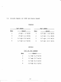
7.I
Grounds Speeds (at 3600 rpm Engine Speed)
FORWARD
'LO'
Gear
1
2
3
4
NHIN
RANGE
Soeed
.5 mph ( .8
.8 mph ( I.2
1.1 mph ( 1.8
I.7 mph (2.7
Gear
km,/h)
kmr/h)
kmrZh)
kmr/h)
L
2
3
4
Soeed
2.5 mph ( 4.0
3.8 mph ( 6 " I
5.7 nrph ( L2
8.5 mph (13.7
REVERSE
rHLn OR nLOn RANGES
Gear
1
2
3
4
Speed
1.1 mph ( I.8 kmr/h)
-1.7 mph (2.7 kmr/h)
2.5 mph (4 .0 km,zh)
3 .8 mph ( 6.1 kmrzh)
24
RANGE
km,zh)
kmr/h)
kmy/h)
kmy'hi
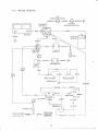
7.2 Wiring Diagram:
PTO
INTERLOCK SWITCH
o**-@-" o**-.@a
*
n
owrul
r r.
II
FWD-REV
SOLENOID
INTERLOCK SWITCH
SWITCH
[][_]
BATTERY
STARTER
MOTOR
WHITE
RED
IGNITION
AMMETER
swlrcH
FUSE
/---:---\
aLncx-{' _ff-*'.'r=-lllr,.
HOURMETER
DARK
BLUE
HEADLIGHTS
ORANGE
RED
l------[-BLAcK
DARK
BLUE
I
GREEN
GREEN
_l_
:
TIME DELAY
MODULE
CONNECTOR
REGULATOR
PUBPLE
-J
WHITE
ROwN----{__l---
25
|
SECTION
8
Set-Up Instructions
8.1
Remove
the tractor from the shipping container.
8.2 Rear Tire Assembly fnstallation:
I. Raise the rear of the tractor.
2. Mount the rear wheel assemblies to the wheel hub with
7/I6-20fi/A hub bolts.
NOTE:
The vaJve stem must be
turned toward the inside of the twin cylinder engine
tractors.
3. Lower the tractor.
4. Adj.uqt. the air pressurB in the rear tires to r0 psi
kN,/mo) to 14 psi (97 kN,/m21.
(69
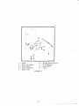
8.3 Front Tire Assembly Installation:
1. Raise the front of the tractor.
2. Put two .813x1.375x1.00 flat washers on each front axle.
See Figure 7.
3. Slide a spacer into the grease seal on the val-ve stem
side of each front wheef.
4. Put multi-purpose grease on each axle.
5. Put a wheelr the valve stem towards the insider or! each
ax1e.
6. Pack multi-purpose grease into each bearing. Make sure
the bearing cages are full of grease.
7. slide a bearing, tapered end first, onto each axle. push
the bearings into the wheels.
8. Put a spacer and then a .565x1.312x.095 flat washer on
each ax1e. Fasten them with the 5/8" lock nuts.
9. Tighten the lock nuts slowly to take up the crearance in
the bearings.
NorE: The front wheels must turn freely with no clearance
in the beari.ngs.
26
6 Spacer
7 - FIat Washer (.656n I.D.)
8-LockNut
9-DustCap
i--Ax1e
2 Flat Washer (.813n I.D.)
3.-Spacer
4-Whee1
5 - Bearing
FIGURE
7
1"0, Install the dust cap.
l,:" Lowen {:he f ront of the tractor
I:. Actjuqt the aj-r pressure.,in the front tires to 14 psi
kN/m') to 18 psi t724 kn/m").
t97
8.4 To Connect the Direction Control Lever:
1. Align the hole in the lower end of the direction control
lever with the hol e in the shifter link and neutral
return strap.
2. Put a clevis pin through the hol-es f rom the outside.
3, Secure with a flat washer and cotter pin.
B.5 Steering Wheel Installation:
L. PUL the steering wheel bushing on the steering wheei
shaft. Make sure the steering wheel bushing fit-s over t"he
nylon bushing in the instrument panel. See Figure E.
2" Put tiie nylon bushing on the steering wheel shaft anci j-ni;e;
the steering wheel bushing.
3, Put the spring on the steering wheel- shaft"
27
7.
E
\\
at^''-"
3--#
t-2
-.
v'
'\-\
'-'
1- Steering Wheel Shaft
5
6
7
8
Steering Wheel Bushing
3- Nylon Bushing
z-
4- Spring
FIGURE
Steering
Wheel
- Flat Washer
- Lock Nut
Steering Wheel Insert
B
"1. Fut the steering wheel on the steering wheel shaft.
5
a .656x1.3I2x.095 flat washer on the steering wheei
" Put
shaft.
fnstall the S/9" Iock nut. Tighten tne nut :o a
torque of 20 ft. Ibs. (27 N,m).
6. Install the steering wheel insert.
8.6 Seat Installation:
1. Tighten the 5/16 hex bolts and Lock washer holding the
seat to the seat springs. See Figure 9.
2. Align the holes in the seat springs with the holes in the
seat pan.
3. Fasten the seat _in _position on the seat pan with the
5/16x3/4 round head bolts, frat washer, and lock nuts.
4. Plug in seat switch.
2B
--4
L3
I
5
1*
2345-
Seat
Hex Bolts
LockWashers
6 - Round Head Bolts
7 - Flat l,Jasher
I - Lock Nuts
9- PIug
Seat Springs
Seat
Pan
FIGURE
29
9
SECTION
LI
9
MITED FIVE-YEAR WARRANTY
6.
This Limited Five-Year Warranly is issued by Gravely
lnternational, lnc,, only to the original purchaser. lf
a.
Gravely equipment is leased by Gravely, this Warranty
shall extend also to the original lessee as if such
lessee were the original purchaser.
Gravely warrants that
2.
placement of items such as spark plugs, belts, oil,
oil filters, air filters, and mower, plow or cultivator
factured by Gravely ("Gravely Products") shall be lree
ol defects in material and workmanship for lhe term
described in paragraph 4, below. Except as hereinafter
provided this Warranty does not cover any engine,
tires or battery iorming a part ol the Gravely Product.
blades, qauOe wheels, skids and other wear iterns.
c.
d.
Product,,varranted
directed
e.
l
l,!o years,
Gr.avel;,.
:ailt.fr:l at, r,ittianted 5v
a
ih! ruirDej' oi m;n159
)
pertCrCt Cl
riil NFSS ;._iR
.1.
:rit\lr' ,{'ta
llra.ir, !- iiAianleIiilr.iV
iiat ,riicyJ lirlil- ::.r, s iri
ir
:
).i)i
you.
9
a. llotify lhe
Gri:v'eiy cJeaier irorn whom you pur'rhascrj the pl,trprncnt
'1
This Warranlv gr\es yrirt :j:,i:.)r{ir-'ieil:r rr(.ltis. iiiC vcr,
ilay have 1]ther riOirts wiriotr vatl lrcrri itl3t€r tu ;tale
0. A Graveiy prrlduci rr,:,Jistralrcn c:lrd is suptlired,flih
Graltiy Prr;dlrcl. Pleasp lrorirDlele thc :iiro and
relurn it to Gravely at lfte itddress l,sied on ttte card.
-fhe
equiUntent regt.istratlon tard will be used by
Gtavelv for:
eaci'r
if ycu have irrOved and it is not convenient lo notily
the seilinc Cealer norify lhe
nr-.arest Gravely
rJealer. You shculd suppiy thrs dealer with a copy
ol tne bili ot saie as prool of the dale ol purchase.
a. I?ecording drrte i:i prrrcl.ase
b. Notification of owners irr compiierrr:e with
afranqements to have the equipment oea.,
below)
d.
Y ajF
appiy tt, _vCu Some Slatrj:'. tl,; nit'i]lli)r/'nL).:ri',,jSlcri
or limitati.rn oi incidenial {_;i crjlsr.rlu€_riiiar .jar|ages,
SO the tbi.,,e jtilltlaliOr :/ o ialr.t,sr,Ji, ..)j,, rrot aDn v /l
Since purChar^e.
livered tc the dealer (refer to paragraph 6
(1o
{rnDlted'.va,tarnl. tasl,c iii)
Oir a Gravely PrcduCt
iirrcludinq 3n,,, italierv oi o!hi'r comoorent nOi manula("iul'eC l/ {lra!€- )/), USe lhts procerlLlre
c. !lake
S t'J:r Oi'rlfr LiL'ni:SS 'lR
lr/t-hr- l-JAl.il ABll-;l
B. Scme slalles
I'o itb,lair',Varranl',. Sei'zi.-'e
D
:,irtt
AN\'WARflAi!-i \', li'{.ri '.ji,rri.,lG ;ri.j i \r,'T - V,rrf-l
T{), lir.3iL.i l-Y FCI: lil{'rlN-\:\ri,rl jr':F- , r[ f{ i i.i .,]i-i
PURCIIAS[ {)F RI t)l ,\i-F !,rt-]fJl : .r liirVrl;l
;r''
FC)il t_(,tss {)i: PSor:ir'! r.lli .., r i ,:ir i'( $.ri\ri:ili t;rl
:werve i12i ,nor:irlS only if a battery sl-rali fail wilhin
,t:ri,,,e i1 :r) a it :l-t-q ci nrrrcnase ihe repiaCemenl Cost
ihereoi sh,lrl b(t troraleLr c,vtr a lwelve-monlh terin
DaSed uiror-r
llirj Jse,.ji
FAFTICIjL.AR i'l tnpC-(l:: ,11_L /r'AFnAN'i;L-:S \i: i:
LltillTED lll DUil,tii:r'i; rO -tlE -FRVlj SEI i,1r; j ,..r
P4|:TAGRAPI-14 Ailtr',.rr: ijllAl:::r,, j:1Ar , , tAV': i.,i,_;
LlABll l'f'/ IOR ittl;;i,];,11 IAi Ji? i-)Orr;S'L:;i r:N r ;Ai
DhL4t"GE', ilEil,L :lNlt; FflOl'4 rilfr !'Jf'r:a/- i 1:'
:gret:s io repair
G.avel,r, iOr
GnAVf:tY MAKf
-l-liE
cr.-eplact-: .tclcciive Gravely Products used exciulvu , lor .:,erscnal, famrly or househcld purposLas
.)!ti)' i.r :rc .t\ir-:r-rt thal lht. i:osl of such wallanty
r.Jvcrert 'e0ati j r .r'i-rlaceineni excer;is $50 00
Any repnir occasicle(j o)i
sef\/r{rrl
jnlerr:.lilce wtil \..rril
iMPl tED !\ARFANTiEi.i, {)R w/\rii;,r,Ni]F.il .f ::, 'i_:
after li-ie scr..lld year (24 months from date o{
f .iichase) inal' tte subject to a $50.0C iJeduciible iirr
,i,i1
n-:a
Warranty.)
7
other
purposct; iL-o|rlrnei'cial use), excluding rental firrns.
Gravely Droducls r.iseC ior renlal p,lrposes will be
warianled 1a)r :i,' days. Reparr of G;avel1 Prcrrjucts
i;;rr
cr-rs.
attachment not 3p!rLrved by u,'avel,,' I i ne l:e ,l
Srty SUCfr r,rnlnprOr'ed aita.thn)err ,.,,tii .,ail 1l)t
,urcrlase rjale f cr Gravely Prod::iriS uSed exClusrvely
tor pcrsoltai, i:irnrly or ii.;usehold purposes, and two
re
in ilte appiicalije nraituai or
insti'uclron. i ncorrect use,tr
lhis Warranty.)
This Warranty is fcr live years (60 months) from
each
Any repair or replacement cccasjoned by
torner negiecl or lacx of prcpei nraintenancc. {The
pUrchaser is responsible for naking Sr.ji'e llrat
Gravely Products arre operated ard serv'jced as
hereunder shall be defective or f ailto conform with this
Warranty, Gravely shall, subject to lhe provisrons
hereof, pay tor, or provide Iabor and materials lor, tne
reDair or replacemenl of such defective Gravely
Product
ears /:14 rtionths) for prodlcls ilseC ior
Any Gravely Product which has been altered or
modified rn any way.
Engine and iires are covered by and subject to
separate warranlies ol the manufacturers thereof.
',
Transporlation to the Gravely dealership. (lf the
Gravely dealer provides transportation, he will
charge for such service.)
b. ,Normal maintenance services and normal re-
all new equipment manu-
ln the event that any Gravely
This Warranty does nol cover lhe following:
the
Consumer Product Safety Act, shoulC any notificalion be necessary.
lf you have any questions concerning the Gravely
Limited Warranty, they should be referred to:
The return of such card is necessary for your warranty
lo be effective.
Gravely lnternational, lnc.
One Gravely Lane
Clemmons, NC 27012
Attn: Customer Service Deparlment
1
e. Warranty service on Gravely Products must be
1. This Warranty is not subject to change or modification
by anyone, including Gravely dealers and no Gravely
dealer is authorized to make any representations or
promises on Gravely's behalf.
AGRAVELY
pertormed by an authorized Gravely dealer.
One Gravely Lane, Clemmons, NC 27012
30