1
Trademark of Bombardier Limited
model
V.I.N.
purchase date
warranty expiry date
DEALER IMPRINT AREA
Text by:
The following are trademarks of Bombardier Limited.
Technical Information Centre
After Sales Service Department
Bombardier Limited
Valcourt, Quebec
Canada, JOE2LO
BOMBARDIER
SKI-DOO
ALPINE
BLIZZARD
CARRY-BOOSE
ELAN
ELITE
Suggested Retail Price: $2.75
(First copy free with unit purchased)
EVEREST
MIRAGE
NORDIC
OLYMPIQUE
SKI-BOOSE
T'NT
MOTO-SKI
FUTURA
SPIRIT
NUVIK
SONIC
BOMBARDIER LTEE/LTD
Groupe des produits recreatifs
Recreational Products Group
Valcourt, Oue., Canada, JOE 2LO
Telephone 1514) 532-2211
Cable Bombarsnow, Telex 05/832550
Valcourt, Que.. Canada, JOE2L.O
Telephone (514) 532-2211
Cable Bombarsnow, Telex05 /832550
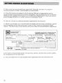
Mar chI, 1 9 7 9
ERRATUM
Dear Customer,
As an owner of a 1979 Blizzard 7500 or 1979
Super Sonic LC, we wish to advise you of a
couple of errors that were made in the specifications given on page 26 of the Operator
manual.
Would you please correct the following items:
carburetor adjustments
air screw 1 1/2 turns! 1/8
engine head nuts (torque)
22 N.m (16 ft-lbs)
We thank you for your understanding and cooperation and wish you pleasant spring snowmobiling.
TECHNICAL INFORMATION CENTER
GROUPE BOMBARDIER MLW
BOM
Mi W l;HOUP
CONGRATULATIONS ... You are now
the
owner of a nevv 1979 snowvehicle is the result of incomoarabte teamwork between Bomrt.r..,.....
and techthis vehicle is
enomeereo with
nr>i'"\'-C'
mind.
The information has been
to
of a
the owner I
new snowmobile with
various ve·hide
owner-related maintenance/ and
instructions.
This is
"Ihe Snowmobile Safety
Booklet' and
the
Manual'. Each is insepause of the product,
with the vehicle at
This manual
formation r1nt"'~"'Tl r<
symbols:
.... WARNING: Identifies an instruc. . . tion which, if not followed, could
cause
injury.
. . . CAUTION: Denotes an instruc"
tlon which, if not followed, could
severely damage vehicle components.
..
O
NOTE: Indicates
information needed to
plete an instruction.
Although the mere reading of such information does not eliminate the hazyour understanding of the inferYY\~'TIr\,n will promote its correct use.
Ride safe and have fun.
Recreational Products Group
Bombardier Limited,
Valcourt,
Canada
Observe the following precautions:
@l
@l
@l
@l
@l
@)
@!
@)
@)
@!
2
Throttle mechanism should be
checked for free movement before
starting engine.
Engine should be running only when
pulley guard is secured in place.
Never run engine without drive belt
installed. Running an unloaded engine can prove to be dangerous.
Never run the engine when the track
of the vehicle is raised off the
ground.
It can be dangerous to run engine
with the cab open.
Since engine cooling is fully in effect
only when the vehicle is in motion
and driven on snow, it is not recommended that you allow the engine
to idle for more than brief periods
and lor you drive the vehicle on icy
surface. Prolonged idling and lor
continuous driving on ice may cause
engine damage.
Gasoline is flammable and explosive
under certain conditions. Always
perform procedures in a well ventilated area. Do not smoke or allow
open flames or sparks in the vicinity.
If gasoline fumes are noticed while
driving, the cause should be determined and corrected without delay.
Your snowmobile is not designed to
be operated on public streets, road
or highways. In most States and
Provinces, it is considered an illegaloperation.
Maintain your vehicle in top mochanical condition at all times.
Your snowmobile is not designed to
be driven or operated on black top,
bare earth, or other abrasive surfaces. On such surfaces abnormal and
excessive wear of critical parts is
inevitable.
@)
@!
@!
@!
@)
Only perform procedures as detailed
in this manual. Unless otherwise
specified, engine should be turned
OFF for all lubrication and maintenance procedures.
Installation of other than "stock"
equipment, including ski-spreaders,
bumpers, pack racks, etc., could
severely affect the stability and
safety of your vehicle. Avoid adding on" accessories that alter the
basic vehicle configuration.
When removing coolant tank cap,
first place a cloth over cap then turn
cap to its f rst step to release
pressure.
The snowmobile engine can be
stopped by activating the emergency cut-out or tether switches, or
turning off the key,
This vehicle is designed tor the
driver only. No provisions have been
made for a passenger.
Please read and understand all other
warnings contained elsewhere.
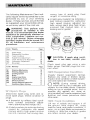
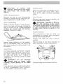
CONTROLS I INSTRUMENTS
Throttle control lever, brake control lever, ignition switch, headlamp dimmer
switch, emergency cut-out switch, tether cut-out switch, rewind starter handle,
primer, tachometer, temperature gauge, cab opening, tool compartment, fuel
4
gauge
BREAK lIN PERIOD
.
Inspection, inspection check list.
1
fUEL MIXING
Recommended gasoline, recommended oil, fuel mixture ratio, fuel mixing procedure
1
PRE-START CHECK
Check points
.
...................... . 9
STARTING PROCEDURE
Ernerqencv starting . . . . ..
.·
1 «)
lUBRICATION
Frequency, pullev guard removal, drive belt removal, steering mechanism, chaincase oilleve!, slide suspension, rotary valve system
_
11
MAINTENANCE
Spark plugs, suspension condition, track condition, suspension adjustment, track
tension and alignment, carburetor adjustment, drive belt, steering mechanism,
steering adjustment, cooling system, brake, engine head nuts, engine mount nuts,
exhaust system, vehicle general inspection, headlamp beam aiming, bulb replacement . o. . ....•.
13
0
• • • • • • • • • • • • • • • • •
,
•••
,
• • • • • • • • • • • • • • • • • • •
STORAGE
Cooling system. track, slide suspension, ski assembly, controls, chaincase, fuel
carburetors, cylinder lubrication, drive pulley, chassis, general inspection .18
PRE-8EASON PREPARATION
Pre-season preparation chart. . . . . . . . . . . . . . . . . ..
TROUBUE SHOOTING GUUlE
TOOLS,
_. . ..
.
,
.
,,
_
.. , , . . . .
25
SPECIfICATIONS,
HOW TO IDENTIfY YOUR SNOWMOBILE. .
1~19 "UMBTED WARRANTY"... ..
.. .. . . ..
.,.'
OfTEN ASKED QUESTIONS. _
_
CONSUMER GUIDE. . . . . . . . . . . . . . . . . . . . . . .
USTING Of AREA DISTRIBUTORS . . . . . . . . . .
CHANGE Of ADDRESS AND OWNERSHIP
22
23
.
30
32
.,
,
,.
.. , . 26
, .. 21
, . 28
_.. 33
35
3
.......
r-----------.-.-.~.-----,-
A) Throttle Control Lever
B) Brake Controt Lever
C) Ignition Switch
D) Headlamp Dimmer Switch
E) Emergency Cut-Out Switch
,-
F)
Tether Cut-Out Switch
Rewind Starter Handle
H) Primer
I) Tachometer
J) Coolant Temperature
Gauge--.1
,
G)
Located on right side of handlebar.
When compressed, it controls the engine speed and the engagement of the
transmission. When released, enqmo
speed returns automatically to idle.
Located on the left side of handlebar.
When compressed, the brake is ap··
olied. When released, it automatically
returns to its original position. Braking
effect is proportionate to the pressure
applied on the lever.
OFF
,.".. ON
Key operated, 2 position switch (OFF /
ON). To start engine, first turn key
clockwise to ON position. To stop en"
gine, turn key counter-clockwise
OFF position.
NOTE: When the key is turned to
the ON position the lights will
also be on as soon as the engine will be
turning.
O
4
The dimmer switch, located on left side
of handlebar, allows correct selection
of headlamp beam. To obtain high or
low beam simply depress switch.
A push button switch located on right
side of handlebar. To stop the engine
in an emergency, press button down
into lower position. Before re-starting
engine always depress button into re..
leased upper position. The driver of
this vehicle should familiarize himself
with the function of this device by
using it several times on first outing.
Thereby being mentally prepared for
emergency situations requiring its use.
WARNiNG: If the button has
been used in an emergency situation the source of malfunction should
be determined and corrected before
restarting engine.
Attach tether cora to wrist or other
convenient location then snap tether
cut-out cap over receptacle before
starting engine.
If emergency engine "shut-off" is required completely pull Gap from safety
switch and engine power will. be automatically shut "off".
O
NOTE: The cap must be installed
on the safety switch at all times
in order to operate the vehicle.
WARNING: If the switch is used
in an emergency situation the
source of malfunction should be determined and corrected before restarting engine.
Auto rewind type located on right hand
side of vehicle. To start engine, pull
handle.
A push-pull button located alongside
manual starter handle. Pull and push
button (2-3 times) to activate primer.
The primer should always be used for
cold engine starts. After engine is
warm however, it is not necessary to
use primer when starting.
The tachometer registers the impulses
of magneto. Direct-reading dial indicates, in thousands, the number of revolutions per minute (F-lPM) of the
engine.
_
CAUTION: The tachometer is
.".. protected by a fuse. If tachometer stops operating, check fuse condition and if necessary, replace. The fuse
is 0.1 amps. Do not use a higher rated
fuse as this can cause severe damage to the tachometer.
The gauge indicates engine coolant
temperature. Normal operating temperature is between 50° to 80° C
(120° to 1800 F), (coolanttemperature
can vary depending on driving and
snow conditions). However, should the
pointer of the temperature gauge touch
the red zone, reduce speed and run
vehicle in loose snow or stop engine
immediately.
WARNING: Before removing the
cap always release the pressure
by placing a cloth over the cap and by
partially unscrewing it (first step). If
this is disregarded loss of fluid and
possibility of severe burns could occur.
To open cab, unfasten latches on both
sides near footrest where cab meets
frame. Always lift cab gently up until
stopped by restraining device.
WARNING: It is dangerous to run
engine with cab open. Personal
injury could result.
5
Located under the cab. To gain access,
tilt cab. Ideal location for spare plugs,
belt, rope, etc.
To check fuel level, simply unscrew
fuel tank cap and withdraw dipstick.
WARNING: Never use a lite
match or open flame to check
fuel level,
With Bornbardier-Hotax engines, a
break-in period of 6 to 10 operating
hours is required before running the
vehicle at full throttle. During this period, brief full throttle accelerations
and constant speed variation will contribute to a good break-in. Continued
wide open throttle accelerations can be
detrimental. Never let your engine
overheat.
CAUTION: Incorrect or lack
a
break-in period will result in engine
horsepower loss.
As with any precision piece of mechenieal equipment, we suggest that after
the first 10 hours of operation or 30
days after the purchase, whichever
comes first, that your vehicle be
checked by your dealer. This inel'st>
tion will give you the opportunity to
discuss the unanswered questions you
may have encountered during the first
hours of operation. Remember that it
is easier to remedy at this time than to
allow the snowmobile to operate until
a possible breakage occurs.
The 10 hours inspection is at the ex··
of the vehicle owner.
6
Engine mount nuts
Muffler attachment
Chain case oil level
Engine coolant level
,---------_.
Rotary valve reservoir oil level
---,
Brake operation and lining condition
._------------
Skis alignment (runners condition)
Pulley alignment and drive belt condition
-,,~-----,-,---------------------_+-_l
Track condition. tension and alignment
._-----,------,---_._-------------------+-lubricate (steering suspension)
"----Electrical wiring (loose connections, stripped wires, damaged insulation), tighten all loose
bolts, nuts and linkage
eration of lighting system {HI / LO beam, brake light, etc.). test operation of emergency
t-out switch
We recommend that you have your dealer sign this inspttetion.
Date of 10 hour inspection
Dealer
7
Oil must be added to the gasoline in
pre-measured amounts then both oil
and gasoline should be thoroughly
mixed together before fueling the tank,
The correct gasoline is regular gasoline
(not less than 92 octane), available
from all service stations.
CAUTION: Never experiment
with different fuel Or fuel ratios.
Never use low lead or non leaded gasoline, naphtha, methanol or similar
products.
Use concentrated Bombardier snowmobile oil available from your dealer.
This type of oil has specially formulated
oil bases to meet the lubrication requirements of the Bombardier-Hotax
engine.
To mix the gasoline and oil always USe
a separate clean container. Never mix
directly in your snowmobile tank. For
best results, acquire two containers, either plastic or metal. Draw from one
until empty then use the second one.
WARNING: Gasoline is flarnmable and explosive
conditions. Always perform Pf()CEldurea
in a well ventilated area. 00 not
or allow open flames or sparks in
vicinity. If gasoline fumes are noitice'(1
while driving, the cause should
termmed and corrected without
Never add fuel while engine is rurmllnq,
Avoid skin contact with fuel at
freezing temperatures.
1. Pour approximately one gallon of
qasoline into a clean container,
If Bombardier snowmobile oil is unavailable substitute with a high-quality
2 cycle snowmobile oil.~he oil / ~as
mix must meet the vehicle requirements, See oil manufacturer recommendations on container.
CAUTION: Never use outboard
or straight mineral oils.
The importance of using the correct
fuel.rnixture cannot be overstressed. An
incorrect fuel ratio results in serious en~Jine damage. Recommended fuel ratio
is 50 /1.
S.l. Measure
500 mL oil to 25 liters
=
50/1
Imperial Measure
1 can 16 oz oil to 5 Imp. gals
50/1
U.S. Measure
1 can 12 oz oil to 5 U.S, gals = 50/1
O
N
. OTE: To facilitate fuel mixing oil
should be kept at room temperature.
8
2. Add the full amount of oil.
3. Replace container cap and shake
the container thoroughly.
4. Add the remainder of the gasoline.
5. Once again thoroughly agitate the
container. Then using a funnel with
a fine mesh screen to prevent the
entry of water and foreign particles,
transfer mixture from container into
the snowmobile tank.
NOTE: When using pre-mixed
fuel, always shake the container
thoroughly as the oil has a tendency
to settle.
WARNING: Never 'top up' gas
tank before placing vehicle in a
warm area. At certain temperatures,
gasoline will expand and overflow.
~
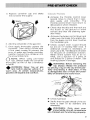
Activate the throttle control lever
several times to check that it operates easily and smoothly. The
throttle control lever must return to
idle position when released.
~
Check that the skis and the track are
not frozen to the ground or snow
surface and that the steering operates freely.
~
Activate the brake control lever and
make sure the brake fully applies before the brake control lever touches
the handlebar grip.
~
Check coolant level. Liquid should
be 2.5 em (1") below filler neck. If
additional coolant is necessary, always use a 50/50 (50 parts of water
for 50 parts of antifreeze) solution.
When entire system has to be refilled, use a solution of 3 parts of
anti-freeze for 2 parts of water. See
cooling system in storage.
a
WARNING: Before removing the
cap always release the pressure
by placing a rag on the cap and by partially unscrewing it (first step). If this
is disregarded loss of fluid and possibility of severe burns could occur.
~
Check fuel level
~
Verify that the path ahead of the vehicle is clear of by standers and
obstacles.
WARNING: Only start your
snowmobile once all components
•
are checked and functioning properly.
9
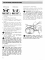
Upper
before
engine
lower position
to stop engine
Should the rewind starter rope
and break, the enqine can be started
with an emergency starter rope.
WARN!NG: Do not start
vehicle by the drive pulley unless it
is a true emergency
have the
vehicle repaired as soon as possible.
i. insert key in ignition and turn to ON
position.
2. Test throttle control lever.
3. Activate primer (2 to :3 times]. Prim-
Tilt pulley
forward
the emergency rope
drive pulley between
and the roller guard.
per usual manual "h"··"nr<
er is not necessary when engine is
warm,
4, Make sure the tether cut-out cap is
in position and that the cord is at
tached to
body, Check that the
ernergency cut-out button is in the
released upper position.
5. Grasp manual starter handle firrnly
and pull slowly until a resistance is
felt then pull Vigorously. Slowly release rewind starter handle.
WARNiNG: Do not apply throttle
while starting.
6. Check operation of the emergency
cut-out switch, and the tether
switch. Restart engine.
WARNING: If engine does not
shut-off when applying the emergency cut-out switch and lor when
puIHng the tether cut-out cap, stop the
engine by turning off the ignition key.
Do not operate the vehicle further, see
your dealer.
7. Allow the engine to warm before
operating at full throttle.
CAUTION: Since engine cooling
is fuliy in effect only when the vehide is in motion and driven on snow,
it is not recommended to allow engine
to idle for more than brief periods
and / or to drive the vehicle on icy
surface. Prolonged idling and or continuous driving on ice may cause engine damage.
10
WARNING: When
vehicle in an emergency situatlon
by the drive pulley, do not make a knot
at the end of the emergency rope .
Routine maintenance is necessary for
all mechanized products, and the
snowmobile is no exception. A weekly
vehicle inspection contributes to the
life span of the snowmobile as well as
retain safe and trouble-free operation.
It is recommended that the steering
system and suspension, be lubricated
rnonthlv or every 40 hours of operation. If the vehicle is operated in wet
snow or in severe conditions these
Items should be lubricated more frequently.
WARNING: Only perform such
procedures as detailed in this
manual, it is recommended that dealer
assistance be periodically obtained on
other components / systems not covered in this manual. Unless otherwise
specified, engine should be turned OFF
for all lubrication and maintenance
procedures,
.
WARNING: Never start or run
engine without drive belt in•
stalled, Running an unloaded engine is
dangerous.
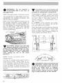
1. Tilt cab and pulley guard, unlock
and raise driven pulley support.
Driven
pulley
support
2. Open the driven pulley by twisting
and pushing the slidin~) half. Hold in
fully open position.
WARNING: Engine should be
running only when pulley guards
are secured in place.
Tilt cab. To tilt drive pulley guard remove clip and unscrew wing nut (A).
3. Slip slackened belt over the top edge of the sliding half.
If necessary to remove driven pulley
guard remove nuts (S) and (C).
4. Slip the belt out from the drive pulley and remove completely from
vehicle. To install drive belt, reverse
procedure.
11
o
NOTE: The chaincase oil capacity
is approximately 256 m L (9 oz.).
Usinq a low pressure
gun, lubricate the idler
with low ternperature qrease Pump 3 to 4 times
through the grease fittin~l located Or)
each cap of the rem idler wheels.
off excess.
Lubricate ski legs at grease fittings until
now grease appears at joints. Oil ski
/ coupler bolts.
CAUTION: Do not lubricate
throttle and / or brake cable
Usirl~l
the spark plug socket, remove
the filler cap then usmq a ri<;pd wire as
a "dipstick" check oil level. The oil
level on the
rnrn (3" to
essary.
12
should be 7590
'). Fieplenish as nec-
Check reservoir oil level
Level should not be below
plastic reservoir 11 necessarv replenish
to oil level line using "Castro] lniector
Oil" or
available horn your
dealer.
The following Maintenance Chart indicates regular servicing schedules to be
performed by you or your servicing
dealer. If these services are performed
as suggested, your snowmobile will give you many years of low-cost use.
WARNING: Only perform such
procedures as detailed in this
•
manual. It is recommended that dealer
assistance be periodically obtained on
other components I systems not covered in this manual. Unless otherwise
specified, engine should be turned OFF
for all lubrication and maintenance
procedures.
Weekly
W4
W5
WI)
IN7
M5
M6
M7
M8
Spark Plugs
Suspension Condition
Track Condition
Suspension Adjustment
Track Tension and r\lignrnent
Carburetor Adjustment
Drive Belt
Steering Mechanism
Steering Adjustment
Cooling System
Brake
Engine Head Nuts
Engine Mount Nuts
Exhaust System
Vehicle General Inspection
Headlamp Beam Aiming
_."-~._--_
..
13
13
13
14
14
15
16
@
A light grey insulator tip indicates a
lean mixture caused by: carburetor
high speed mixture adjusted too
lean, wrong spark plug heat range,
incorrect fuel mixture ratio, or a
leaking seal or gasket.
Overheated
(light grey)
Fouled
{black}
_
CAUTION: If spark plug condi"
tion is not ideal, contact your
dealer.
Page
Check spark plug gap using a wire
feeler gauge. Reinstall plugs and connect wires.
16
16
16
17
17
17
17
17
17
Visually inspect suspension springs.
Replace any weak or broken spring.
Inspect shoe condition of slide suspen-sian and replace as necessary.
~_.~._-~._-~
Disconnect spark plug wires and remove spark plugs. Check condition of
plugs.
@
@
Page
Code Monthly
Ml
M2
M3
M4
wrong type of spark plug (heat
range), or excessive idling.
A brownish tip reflects ideal conditions (correct carburetor adjustment, spark plug heat range, etc.).
A black insulator tip indicates fouling
caused by: carburetor idle speed
mixture and/or high speed mixture
too rich, incorrect fuel mixing ratio,
O
NOTE: During normal driving,
snow will act as a lubricant and
coolant for the slider shoes. Extensive
riding on ice or sanded snow, (not to
mention dirt, asphalt, etc. never reo.
commended) will create excessive heat
build-up and cause premature slider
shoe wear.
Lift rear of vehicle and support it off
the ground. With engine off, rotate
track by hand, and inspect condition. If
worn, cut or track fibers are exposed or
missing or defective inserts or guides
are noted, contact your dealer.
13
WARNING: Do not operate a
snowmobile with a cut, tom, or
damaged track.
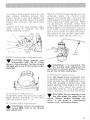
The suspension is adjustable, the front
adjustment for surface condition, the
rear for driver's weight.
When the front adjuster blocks are at
the lowest elevation more weight is
distributed on skis. At the highest position the weight is transferred from the
skis to the track. The rear adjuster
blocks should be adjusted to suit the
driver's preference.
::::::~:Adj~I~~~- --blocks
CAUTION: Too much tension will
result in power loss and excessive
stresses on suspension components.
If necessary to adjust. Loosen the rear
idler wheel retaining screw and then
loosen or tighten adjuster bolts located
on inner side of rear idler wheels. If
correct tension is unobtainable. COl',tact your dealer.
O
NOTE: Track tension and alignment are inter-related. Do not adjust one without the other.
Start the engine and accelerate slightly
so that track turns slowly. Check that
track is well centered I. E. equal distance on both sides between edges of
track guides and slider
CAUTION: Always turn left side
adjuster blocks in a clockwise direction, the right side blocks in a counter-clockwise direction. Left and right
adjuster blocks of each adjustment
must always be set at the same
elevation.
Lift rear of vehicle and support with a
mechanical stand. Allow slide to extend normally. Check the gap 13 rnm
{112") between slider shoe and bottom
inside of track If track tension is too
loose, the track wiil have a tendency to
thump.
14
WARNING: Before checking track
alignment, ensure that the track
is free of all particles which could be
thrown out while track is rotating.
Keep hands, tools, feet and clothing
dear of track. Ensure rio-one is standing in close proximity to the vehicle.
To correct, stop engine loosen the rear
idler wheels retaining screws then
loosen the lock nuts and tiqhten the
adjuster bolt on side where the slider
shoe is the furthest to the track insert
guides.
Tighten lock nuts and recheck alignment. Ensure to retighten the idler
wheel retaining screws.
------...---.....
With the throttle cable adjuster jam nut
unlocked, press the throttle lever
against the handle qrip. Unscrew the
cable adjuster manually to obtain maximum carburetor slide opening. (With
the air silencer removed, check with
your finger if the carburetor slide is well
seated against the carburetor top portion). Then, screw the cable adjuster in
two turns in order to nullify any possi
ble tension on the throttle cable then,
tighten the cable adjuster jam nut.
-i
Idler wheel
retaining
screw
CAUTION: Never operate your
snowmobile with the air intake
silencer disconnected. Serious engine
damage will occur if this notice is disregarded.
Cable
adjuster
WARNING: It is important that
the throttle slide adjustment be
performed to ensure proper functioning of the throttle mechanism.
Turn idle speed screw clockwise until
it contacts the throttle slide then continue turning two (2) additional turns.
This will provide a preliminary idle
speed setting. Start engine and allow
it to warm then adjust idle speed to
18002000 F1PM by turning idle speed
screw clockwise or counter-clockwise.
Completely close the air screw (until a
slight seating resistance is felt) then
back off screw 1 turn ±: 1/4.
CAUTION: Do not attempt to set
the idle speed by using the air
screw. Severe engine damage can
occur. If idle speed is unobtainable
contact your authorized dealer.
WARNING: Ensure the engine is
turned Off. prior to the throttle
slide adjustment
15
Inspect belt for cracks, fraying or
abnormal wear (uneven wear, wear on
one side, etc.) If abnormal wear is
noted, probable cause is pulley rnisalignment. Contact your dealer.
Check drive belt width, if less than 30
rmn (1 3/16") replace belt.
O
NOTE: When installing a new
drive belt,' a break in period of
15-25 krn (10-15 miles is strongly re
commended.
Inspect steering mechanism for tightness of components (steering arms, tie
rods, ball joints, spring coupler bolts,
etc.). If necessary, replace or retighten.
Check condition of skis and ski runners. Replace if worn.
Skis should have a toe out of 3 rnm
u/s"). To check, measure distance between each ski at front and rear of leaf
sprinqs. The front distance should be 3
mm (1/8") more than the rear when the
handlebar is horizontal.
IMPORTANT: Close front of skis manually to take ali slack from steering
mechanism.
If adjustment is required:
Loosen the lock nuts of the longer tie
rod. Turn tie rod manually until skis are
properly aligned. Firmly retighten lock
nuts.
16
Handlebar should also be
when the skis are pointed toward front.
To adjust:
Loosen the lock nuts of the shorter
rod. Turn tie rod manually until handle
bar is horizontal. Betightef1 lock nuts
firmly.
WARNING: The ball joint socket
must run parallel with ttlesteering
arm. The socket must be restrain when
tightening the tie rod end lock
Place a cloth over the cap and release
it to the first step to check that the cap
pressurizes the system, if not, install a
new Bib cap. Do not exceed the 13ib.
of pressure. Using a hydrometer check
that the anti-freeze solution is strong
enough for the temperature in which
the vehicle is operated.
O
NOTE: Should the coolant temoerature be above recommended
ranne 50° -80 0 C (120 0 180 0 F),
hose off grime from the heat exchanger
(underneath the frame above the
track) .
The brake mechanism is self-adjusting,
therefore, periodic adjustment is not
required. However, the brake mechanism can be checked by depressing
brake control lever. Brake should apply
fully when lever is 13 mm (Y2 ") approx.
from handlebar grip. If it does not, do
not tamper with the brake, contact
your servicing dealer. Check the stop
light to see if it functions. If necessary,
readjust switch position.
WARNING: Brake pucks less
than 3 mm (1/8" I must be re
placed. Replacement must be performed by an authorized dealer. Always check the stop light to see if it
functions.
With engine cold, check that engine
head nuts are tight and equally torqued
to 39 Nom (28 tt-Ibs).
IMPORTANT: The engine head nut
torque should be checked after the first
5 hours of operation.
.>
, "1 .~.L,
s,
!
"",
'" \
Check engine mount nuts for tightness. Retighten if necessary.
The engine / exhaust system parts are
vital toward efficient muffler function.
Check all attachments. Replace springs
and / or tighten if necessary.
CAUTION: Do not operate vehicle with muffler disconnected
otherwise serious engine damage will
occur.
Check electrical wiring and cornponents, retighten loose connections.
Check for stripped wires or damaged
insulation. Thoroughly inspect the vehicle and tighten loose bolts, nuts and
linkage. Inspect skis and ski runners for
wear,
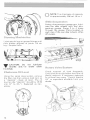
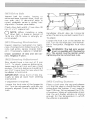
The angle of the headlamp beam has
been pre-adjusted prior to delivery.
Should you wish re-adjustment, place
vehicle on a flat surface 7.6 m (25')
from a wall or screen.
j
90°
Headlamp horizontal
center line
Wall
~-d~;~;;,SIDE VIEW
~
Ground
With the suspension correctly adjusted, the rider seated on the vehicle
and the high beam ON (engine must be
run runq on man ual start models);
check that the center of high intensity
lone of high beam is 50 mrn (2") below
horizontal line of headlamp height.
To adjust, remove headlarnp chrome
ring, turn upper or lower adjusting
screws to obtain desired bearn position.
If headlamp is burnt, tilt cab. Unplug
connector from headlamp. Remove
rubber boot and unfasten bulb retainer
clips. Detach bulb and replace. If taillight bulb is burnt, expose bulb by reo
moving red plastic lens. To remove,
unscrew the two (2) Phillips head
screws. Verify all lights after replacement.
IMPORTANT: It is during summer, or
when a vehicle is not in use for any
length of time that proper storage is a
necessitv. Storage of the snowmobile
during long periods of inactivity consists of checking and replacing missing
broken or worn parts: proper lubrication and treatments to insure that parts
do not become rusted; cleaning items
such as carburetor of ai! mixtures, to
prevent gum varnish formation within
the carburetor; and in genera!, preparing the vehicle so that when tile
time comes to use the snowmobile
again it will start and be in top condition.
WARNING: Only perform such
procedures as detailed in this
manual. It is recommended that dealer
assistance be periodically obtained on
other components / systems not covered in this manual. Unless otherwise
specified, engine should be turned
for all lubrication and maintenance
procedures.
To drain the cooling system, remove
the coolant tank cap and disconnect
the by-pass hose from the fitting on
cylinder head. Block the fitting and
keep the hose as low as possible to
drain the system.
/..c~-_...-A-\,- )9~-
h~99@j
I
\...
18
Q
.~
.... By-pass
Ll
~ _ _. fitting __ ~ __
I
J
However, to completely drain the systern, it is necessary to blow into the
tank through the vent tube, while
blocking the tank filler neck with one
hand to prevent air leakage.
Reconnect by-pass hose and continue
to pour the liquid in the coolant tank
until the coolant level reaches 2.5 rnrn
(1") below filler neck.
Reinstall tank cap and start engine; let
engine run until it reaches its operating
temperature and thermostat opens. AI·
low it to run a few minutes more. Stop
engine and check coolant level; refill as
necessary .
CAUTION: To prevent rust formation in the cooling system, always replenish the system with the
recommended solution (60% antifreeze 40% water).
To refill the cooling system, disconnect
by-pass hose and keep it near fitting on
cylinder head; refill tank and blow into
it through the vent tube, while maintaining the hand over the filler neck until the liquid comes out at the by-pass
hose and the fitting on cylinder head.
O
NOTE: Ensure to maintain a certain coolant level in the tank while
performing this procedure.
WARNING: Before removing the
cap place a cloth over the coolant
•
tank and release the cap to the first
step to release the pressure. loss of
fluid and possibility of severe burns
could occur, if this notice is disregarded.
Inspect track for cuts, missing track
guides and broken rods. Make any
necessary replacernen t.
WARNING: Do not operate a
snowmobile with a cut, torn or
•
damage track.
Lift rear of vehicle until track is clear of
ground then support with brace or
trestle. The snowmobile should be
stored in such a way that track does
not stay in contact with cement floor
or bare ground.
o
NOTE: The track should be rotated periodically, (every 40 days).
Do not release track tension
19
CAUTION: To prevent track
damage, temperature in the storage area must not exceed 38°C
(1 00° F).
Remove any dirt or rust. Grease idler
wheels at grease fittings. Wipe off surplus. Replace worn slider shoes.
Wash or brush all dirt or rust accumulation from skis and springs. Grease ski
legs at grease fittings. Check condition
of skis, ski runners and leaf springs.
Replace if worn or weak.
Apply metal protector on ski assambly. If unavailable, wipe the entire ski
with cloth soaked in oil to prevent rust
formation.
Lubricate steering mechanism. Inspect
components for tightness, (spring coupler bolts, steering arm locking bolts,
tie rods, bail joints, etc.). Tighten if
necessary. Oil moving joints of brake
mechanism.
WARNING: Do not lubricate
throttle and I or brake cable
housing. Avoid getting oil on brake
pads.
Coat electrical connections and switches with a greaseless metal protector.
If unavailable, use petroleum jelly.
20
Drain the chaincase completely and refill to proper level using fresh chaincase oil. To drain, remove chaincase
cover.
Remove cap then using a syphon, remove gasoline from tank.
WARNiNG: Gasoline is flammable and explosive under certain
conditions. Always perform procedures
in a well ventilated area. Do not smoke
or allow open flames or sparks in the
vicinity.
The carburetors must be dried out
completely to prevent gum formation
during the storage period.
Assure that inlet fuel line is disconnected.
Remove plug of the float chamber of
each carburetor. Drain carburetors.
Reinstall plug and connect fuel line.
Engine internal parts must be lubricated to protect cylinder walls from possible rust formation during the storage
period.
NOTE: This operation should be
repeated every 40 days during
storage.
O
Remove spark plugs. Operate rewind
starter to bring piston at top position.
Pour the equivalent of one spoonful of
oil into spark plug hole.
Slowly crank engine several times
using manual starter. Repeat above
steps for other cylinder. Insta!1 spark
plugs.
CAUTION: To prevent ignition
system damage, make sure that
the cut-out button is in the lower position.
Inspection and cleaning must be performed by the dealer at the end of each
season.
Touch up all metal spots where paint
has been scratched off. Spray all bare
metal parts of vehicle with metal protector. Wax the cab for better protection.
o
NOTE: Apply wax on glossy finIsh of cab only. Protect the vehicle with a Ski-Doa cover to prevent
dust accumulation during storage.
_
CAUTION: If for some reason
"
the snowmobile has to be stored
outside it is necessary to cover it with
an opaque tarpaulin. This caution will
prevent the sun rays affecting the plastic components and the vehicle finish.
Check electrical wiring and components, retighten loose connections.
Check for stripped wires or damaged
insulation.
Thoroughly inspect the vehicle and
tighten loose bolts, nuts and linkage.
NOTE: Leave drive belt off pulleys for the entire storage period.
O
Clean the vehicle thoroughly, removing
all dirt and grease accumulation.
CAUTION: Plastic alloy components such as fuel tank, windshield, etc., can be cleaned using mild
detergents or isopropyl alcohol. Do not
use strong soaps, deqreasinq solvents,
abrasive cleaners, paint thinners, etc.
Inspect cab and repair damage. Repair
kits are available at your authorized
dealer. Clean frame. (Use only "Aluminum cleaner" and tallow instructions
on container).
21
Snow is falling and you are now anticipating the next snowmobile safari. If
you have observed and adhered to the
storage procedures outlined in this mao
nual, your vehicle preparation becomes
a relatively easy task.
To simplify the pre-season preparation
have drawn up a small chart. The
chart indicates servicing points to be
performed by you and your servicing
dealer. If these services are performed
as suggested, your vehicle will give you
many hours of fun and low cost USB.
Wf;
IMPORTANT: Observe all Warnings
and Cautions mentioned throughout
this manual which are pertinent to the
item being checked. When component
conditions seem less than satisfactory,
replace with genuinl'J Bombardier parts
or approved equivalents.
To be performed by dealer
•
To be performed by owner
0
Change spark pi(Jgs
Check chaincase oil level
Check drive pulley
Replace fuel filter
Connect fuel lines and check
attaching points
---"------'.......f--~
Check track condition, tension
and alignment
Check coolant condition and level
Inspect drive belt and install
Check throttle cable for damage
and free operation
Inspect brake condition and operation
--_._~~-I
Inspect oil seals for possible
cuts 01 leaks
Check engine timing
Check electrical wiring (broken wire,
damaged insulation)
Inspect condition of starting rope
._-----!-,:.:.....j
Check tightness of all bolts, nuts
and linkage
Refill gas tank
Adjust carburetors
Check oil level of rotary
valve reservoir
Lubricate suspension
22
SYMPTOMS
POSSIBLE CAUSES
DO
Engine turns over but
fails to start or starts
with difficulty
1. No fuel to the engine
Check the tank level and fill up with correct
qas- oil mixture. Check for possIble dogging
ofIuelline, item 5.
2. Spark plug
Check forfouled ordefective spark plug.
Disconnect spark plug wire, unscrew plug
and remove from cylinder head Recnnnect
wire and ground exposed plug on engine
cowl, bein careful to hold away from spark
plug hole. allow engine starting procedure
and check forspark. If no sparks appear, reo
place spark plug If trouble persists, check
item 3.
r
3. Faulty ignition
-
Check for fouled or defective spark plug. Dis·
connect spark plug wire, unscrew plug and re
move from cvchnder head. Reconnect wire and
ground exposed plug on engine, being careful
to hold away from spark plug holo. Follow engme starting procedure and check for spark. If
no sparks appear. replJce spark plug. If trouble
persists, contact your dealer.
-
40 Flooded engine
Remove wetspark plugs, turnignitIOn to
OFF and crank engine several times. Install
dean dry spark plugs. Start engine following
usual starting procedure. If engine GOnttnU8S
toflood, see your dealer.
50 Clogged fuel line {water or
Change filter canridge. Check condition and
cemecuoos offuel lines. Check the deanliness
of fuel tank. _.___.0_._ _ _ _ _
dirt}
6. Faulty carburetor
First make primary adjustments on carhure{See Maintenance Section! If carburetoris still faulty, contact your dealer
forrepair.
tol
7.
100
much oil in fuel
-"
8. Engine timing
----
Engine will not turn
manually
Drain the fuel tank and refill with the correct
gas!nilmixtum.
Engine timing may be defective orout of
adjustment. Contact your dealer.
9. Poor engine compression
Running with alean fuel mixture may pm
duce excessive engine wear resulting mpoor
engine compression. If this occurs, contact
your dealer atnnce.
1, Seized engine
Inthe case ofaseized ongine contact your
dealer. Seizure isa direct result ofpoor lu-
brication.
23
SYMPTOMS
POSSIBLE CAUSES
WHAT TO DO
Engine lacks acceleration or power
1. Fouleo or defective spark plug
Check item 2 ot "Engine turns over but fails
to start or starts with difficuhy".
2. Clogged fuel line (water or
Check fuel line condition. (See item 5 of"En·
gine turns over but fails to stan orstarts wnh
difficultv".!
dirt)
\------------+----.----.-----1
3. Carburetors
Readjust the carburetor. ISee Maima!l511r.tl
seetion). IItrouble persists, contact your dealer.
----.-----.......,f-----------..;
4. Faulty ignition
First check nsm 2 and 3 of "Engine turns over
but fails to start or starts with difficulty". If
the ignition system
your dealer.
8tlil seems
faulty.
COlll&et
5. Engine
Engine continullliy
backfires
1. Faulty spark plug
Check itom 2 (if "Engine turns over butmils to
start orstarts with difficulty".
2. Overheated
Carburetor set too lean. Genlar,l your defiler.
Aeplen~~h coolant level. Check for restricted
or leaking hose lor gasketl,replace as re
quired. Air incoaling system, bleed systmn.
Engine coolant pump inoperative, see yom
dealer.
me
t-----.---..----3. Engine timing incorrectly
Snowmobile cannot
reach full speed
24
1. Drive belt
Check lordamaged orworn drive bett Raplacs
if necessary.
2. Incorrect track adjustment
Check track tension and alignmeot Readjust to
specilicallons. {See Maimenance secnonl
3. Faulty engine
Check item 1 to 5 al "Engine lacks acceleration
Of power".
4. Pulley misalifjned
Contact your dealer.
As standard equipment each new
snowmobile is supplied with a basic
tool kit such as screwdriver, wrenches,
emergency starter rope, etc ...
D
B
A. Screwdriver
D. Socket wrench handle
B. Socket 10/ 13 mm
E. Starter rope
C. Open end wrench '10/13 mm
F. Socket 21 /26 mm
C
25
ENGINE
No. of cylinders
Bore
Stroke
Displacement
Compression ratio (corrected)
Carburetor type
Carburetor adjustments
-- air screw
- idle speed
Engine head nuts (torque)
Cooling system
- 51*
capacity
...- Imp.
-~-
U.S.
Thermostat
~~or_£.:.6ssure cap
CHASSIS
2
59,5 rnm (2.342 in.)
61 mm (2,401 in.]
339.2 em 3 (20.7 in. 3 )
6.9:1
2 x Mikuni VM 34-199
±
1 turn open
1/4
1800-2000 R.P.M.
39 Nom (28 ft-lbs)
4 liters
140 ounces
135 ounces
110°F
13 Ibs
.--.--:-----t---------------------l
Overall length
2'71.8 em 1107 in.l
106 em (41 3/4 in.)
'lO5.4 cm (41 1/2 in.)
86.3 em 134 in.)
3 rnm (1!8 in.)
190.5 kg (420 Ibs)
8181 em2 (1268 in. 2 )
2,282 kPa 10.331 Ib-in. 2 )
Overall width
Overall height
Ski stance (center to center)
Ski alignment (toe out!
Mass (weight)
Bearing area
Ground pressure
POWER TRAIN
I Track
dimensions
Track tension
41.9 em (16 1/2 in.) x 290 cm (114 in.)
13 mm (1/2 in.) gap that should exist between slide shoe and
bottom inside of track
Equal distance between edges of track guides and slider
shoes
Track alignment
19/38
Std. gear ratio
Chaincase oil capacity
Drive belt (minimum width)
256 mL (9 oz.)
3 em (1 3/16 in.I
1-----------------1------_.-.--.----------- ---------1
ElECTRICAL
Lighting system (output)
Heedlamp bulb
Tail/stop light
Spark plug (Bosch) (normal use)
(severe use)
Spark plug (gap)
Advanced ignition timing m.T.D.C.)
130 watts
60/60 W
5/21 W
W34052S
W340S2S
0,50 mm L020 in.]
1.39 rnrn
± 0.10
mm 1.055 in.
:±:. .004 in.) Between marks at
6000 R.P.M.
1--:::::-:-.::.-:-------------+---------.-.------------1
! FUEL
- 51'
Tank
I. capacity
Gasoline
Gas/oil ratio
BRAKE
50/1
-----+.--_.-.------------------j
rake type
~
26.1 liters
5.75 gals
6.9 gals
Regular
- Imp.
-- U.S.
Brake adjustment (control lever)
Brake lining (minimum thickness)
.-
-
Disc, self- adjusting
13 mm (J/2 ln.) minimum distance from handlebar grip when
fully applied
3 mrn (1/8 in.)
'International System
Bombardier Urnired reserves the
product wltllout I[liposing any
26
to make changes indesign and spedftia!ioiJS and/or 10 maks additions IV, orimprovemertts ill its
upon li,slf to Instal/them all lis product prewous/y monutscnuod.
The main components of your snowmobile (engine, track and frame) are
identified by different serial numbers.
!t may sometimes become necessary
to locate these numbers for warranty
purposes or to trace your snowmobile
in the event of theft.
ENGINE
SERIAL
NUMBER
TRACK
SERiAL
NUMBER
_ _ _ VEHICLE SERIAL NUMBER
O
NOTE: We strongly recommend that you take note of all the serial numbers
on your vehicle and supply them to your insurance company. It will surely help
in the event a snowmobile is stolen.
27
BOMBARDIER Limited as manufacturer, warrants FFlOM THE DATE OF FIRST
CONSUMER SALE, every 1979 Ski-Doo snowmobile, sold as NEW J\ND UN
USED, by an authorized SKI·DOO dealer, subject to the
limitations and
conditions, for a period of:
~
two (2) seasons maximum for models:
Olvmpique", Citation', Everoste, Elito@.
€)
Warranty STARTS on the date of sale to the first consumer and ENDS the
SECOND APRIL 30TH following the date warranty coverage
Ninety (00) consecutive days for the foiiowing models:
Blizzarde 5500-75009500 and
to the follo\lvinq:
€)
1. When a sale is made after MM1CH 31ST of a
year but before niE 1ST
DJ\ Y OF DECEMBER of the same year, the ,,,r,""nt,, will start on DECEMBER
1ST
the date of sale.
2. \rVhen a sale is made on lor after ,JANUARY 2ND of a
of the 9.)
as of MARCH 31ST, of
over to the next season,
the 18T DAY OF lJt:ct:I\i1d
Any 1911 m@d~ ;n@'t i~m:~d
<nOOY~ i~
the unused
be carried
;not W'al1rril!;nt~d.
BOMBARD1EH wil!
materia! and i or workmanship
80M BAHDl FR cornnonent V\,llIIUlH
SKI·DOO dealer
~;nd oom~:~(m~;n~:
of the
worn due
breaker
expendable items and / or components that am damsoed
variable
drive
Aim ~:l::cmlJld~<liN:
~
from installation of
other than qenuine
B()fv1B/\~1
En
parts.
~
caused
Ooerator Manual
lubricants cost
merits will be
proper maintenance as detailed In the
each SKI~[)OO snowmobile. The
ail maintenance
tune-ups and
to the owner.
or adjustment of the
sernbiv. The drive pulley assembly is factory sealed, and can
an authorized SK! ..DOO dealer.
4& Damaqe resultinq from improper
<lI
Vehicles used for racing purposes.
€)
Vehicles used for rental or other business purposes.
4&
All optional accessories installed on the vehicle.
(The normal warranty policy for parts and accessories if any, applies).
28
Damage resulting from operation of the snowmobile on surfaces other than
snow.
tiiI Damage resulting from accident, fire or other casualty, misuse, abuse or
neglect.
tiiI Damage resulting from modification to the snowmobile not approved in writinq
by BOMBARDIER.
tiiI Losses incurred by the snowmobile owner other than parts and labour, such as,
but not lirnited to, transportation, towing, telephone calls, taxis, or any other incidental or consequential damages.
Some states or provinces do not allow the exclusion or limitation of incidental or
consequential damages, so the above limitation or exclusion may not apply.
tiiI
Present, to the servicing dealer, the hard copy of the SKI-DOO Customer Regis-
tration card given by the selling dealer at time of purchase.
This warranty gives you specific rights, and you may also have other legal rights
which may vary from lIrtateto lIrtm@. or proYinCEl to proYinCEl.
Whom applicabl@ this warranty is expressly in lieu of all other expressed or implied warranties of BOMBARDIER, its distributors and the selling dealer, including
any warranty of merchantability of fitness for any particular purpose; otherwise the
implied warranty is limited to the duration of this warranty. However, some states
or provinces do not allow limitations on how long an implied warranty lasts, so the
above limitation may not apply.
Neither the distributor, the selling dealer, nor any other person has been authorized
to make any affirmation, representation or warranty other than those contained in
this warranty, and if made, such affirmation, representation or warranty shall not
be enforceable against BOMBARDIER or any other person.
If a servicing problem or other difficulty occurs, we suggest the following:
1. Try to resolve the problem at the dealership with the Service Manager or Owner.
2. If this fails, contact your area distributor listed in the operator manual.
3. Then if your grievance still remains unsolved, you may write to us:
Bombardier Limited
Customer Relations Dept.
Recreational Product Group
Valcourt, Quebec, Canada, JOE2l0
Bombardier Umited NHrves tho right to modify its warranty policy many
timtiil. being undeNtood that such modificm:ion win not alter the warrant,
conditions epplicable to yehides sold while the above warranty is in effect.
JANUARY 1978
BOMBARDiER LIMITED
Valcourt, Quebec, Canada, JOE2l0
"Trademark of Bombardier Limited
.:0;, Registered Trademark of Bombardier Limited
29
Q: Why must my snowmobile be registered? After al! I do have my original
invoice as proof of when I purchased my snowmobile.
A: The information orovided by the Customer Warramy Registration card is
computerized, and all werrentv claims thereafter, are processed by the computer.
Without this valuable information on the Warranty Registration Card, we cannot
acknowledge warranty or notify owners of a possible recal/.
Q: How do I know my vehicle has been registered at the factory?
A. When you bought your snowmobile the dealer should have completed, signed
and forwarded us the manufacturer's copy of the Customer Warranty Registration. The hard copy of the card is your proof that the snowmobile is registered.
Q: If I sell my snowmobile within the warranty period, will the new owner qualify
tor the balance of the warranty?
A: Yes, provided the unit has already been reqistered with the manufacturer.
30
Q: I bought my snowmobile
In O'King County but I snowmobile in Washington
County. Can the dealer in Washington County accept to perform warranty
work on my snowmobile?
A: Yes, any authorized dealer in North America can perform warranty repairs,
providing the customer warranty registration card is presented.
Q: Manufacturer does not accept warranty work on seized, scored or melted
pistons, why?
A: From testing and experience, we know that such piston failures can only be
caused by detonation or pre-ignition, which are directly related to the following
factors and therefore, are beyond the manufacturer's controt.
Lean carburetor settings.
Use of no-lead or tow-teed gasoline or use of regular qssoline when premium
is recommended.
Incorrect oil/gas mixture (too little or too much 011).
Poor quality, outboard or straight mineret oils.
Removal of intake Silencer.
Retarded or advanced ignition timing.
Hot spark piug(s) (improper heat range).
Q: Where can! find information on the lubrication and maintenance of my
snowmobile?
A: In the Operator Manual provided with the vehicle at the time of first sale.
Q: As I read through the warranty, I find that expendable items are not covered.
What are some examples of expendable items?
A: Expendable items are those subject to wear and tear through normal use. To
list a few, light bulbs, spark plugs, brake limi7gs, belts, suspension and ski runner
shoes, etc...
31
our product you will receive:
SERVICE - from the product itself
SERVICE - from the dealer who sells the product
If, however, the service or product is unsatisfactory,
Return to your dealer's service department and discuss the details
of the problem with the manager. He is in a position to help you with
aU maintenance and service needs. If the matter cannot be resolved,
he may want to bring the sales manager or the general manager into
discussion.
if the dealer cannot solve the situation.
Write to your nearest area distributor.
TEll HIM THE FACTS
•
•
Ell
Vehicle identification number.
Date of purchase.
Name and address of your selling dealer.
• Your name, address and phone number.
• The specific problem.
The matter wi/! receive immediate attention from the distributor's service department
If at this point your grievance still remains unresolved, contact
Bombardier limited,
Valcourt, P.O. JOE2l0
AU'n Customer relations
Provide all necessary details (including names of persons previously
contacted). Your problem will be reviewed and instructions wi!1 be
provided to the persons responsible for product service in your area
or we may contact you directly.
32
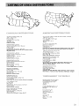
Al.PINE DiSTRIBUTORS l.TO
3206 -_. 26th Street
P.O. Box 159
Va-rnon, British Columbia
vir 6M2
16041 [i45,1314
British Columbia
BOMBARDIER LIMITED
Eastern Canada Distribution Division
Atlantic Brand-j
P.O. Box 670
Sbediec. New Brunswick, EGA3GO
New Brunswick. Nova Scotia, Prince Edward Island,
Magdalen Island
BOMBARDIER LIMITED
Eastern Canada Distribution Division
Quebec Branch
Valcourt,OuebBc. JOE2LO
MIl.l.ER EQUIPMENT AND RECRE,;TiON,\l.· CENTER
1049 Vvhitnev Rn'3d,
p.
Box 3~13B, Anchorage
o.
Alaska 99501
i90712749513-14,15
Alaska
El.LlOTT [j HUTCHINS INC.
East Main StreRt Road
Malone, New York
15161483-4411
Connecticut, Delaware, Maryland, Massachusetts, New Jersey.
New York, Pennsylvania, Rhode Island, District of Columbia
TIMBERLAND MACHINCES INC,
10 North Main Stmet
Lancaster, New Hampshire 035PA
16031 788-4738
Maine, New Hampshire, Vermont
15141532-2211
BOMBARDIER CORPORATION
Quebec, Eastern Ontario
4505West SUP13rior Street
PO. Box 6100
BOMBARDIER LIMITED
Eastern Canada Distribution Division
Ontario Branch
.28Currie Street
Barrie, Ontario, L4M 452
1705!728-8600
Ontario,Mn Eastern of Ontario
North Dakota, South Dakota, Minnesota, Wisconsin, Iowa.
Illinois. Missouri, Michigan,lndiana, Ohio, Tennessee,
Kentucky, West Virginia
BROOKS EQUIPM ENT
1616 King Edward Street
PO, Box 005
Winnipeg, Manitoba, R3C 2V8
Duluth, Minnesota 55806
12181626-2881
BOMBARDIER WEST INC,
a19 WfJst Broadway
Idaho Falls, Idaho 83401
12081 523-6870
Callfomle, Nevada, Montana, Idaho, Wyoming, Utah, Colorado,
New Mexico, Arizona, Kansas, Nebraska. Washington, Oregon
12041633-724"1
Manitoha, Saskatchewan
HUDSON'S BAY CO,
165 Hvmus Boulevard
POInte-Claire, Quebec, M4W lA8
1514! 697,6500
North-West Territories, Franklin District & Keewatin
J,W. RMWAl.L l.TD
PO, Box 757
'Wast S t-eet
Corner Brook, Newtoundtand, A2H 6G7
1709! 634-3-')33
Newfoundland, labrador
TRACT EOUIPMENT LIMITED
14325, 114th Avenue
Edmonton, Alberta, ToM 2Y8
14031 41>2·9910
Alberta, Dist. McKenzie, Yukon, N,W,T,
BOMBARDIER,ROTAX GmbH
Vienna Branch, P.O. Box 86
Dcneutelderstresse za-va
1210 Vienna
Austria
COLBJORNSEN & CO. A / S
P,O. 80;,( 80,1341 Bekeostua
Norway
KY l.AATUVAUNU
ltafahdenkatu 25
SF-0021O Helsinki 21
Finland
MOVAC AS
BOX 791
S901 - 10, Umea
Sweden
33
------_.~----
---_._-----
-_._-_.._ ------_.._ -------------_.
...
---------~-----_._
._~-----,------
---_...._---_.
34
,------------
Any change in address or ownership should be brought to the attention of the
manufacturer by completing and sending out the card supplied below. This
will help us to maintain our files up-to-date.
VEHICLE IDENTIFiCATiON NUMBER
NAME
NO
_-_
----- ...
CITY
APT,
STREET
_-------STATE
..,,-..
llP./ POSTAL CODE
NAME
NO
STREET
APT,
VEHICLE iDENTIFICATION NUMBER
The ownership of this vehicle is transferred
--------_._-_
..•_--_.
NO
APT,
STREET
-------_
..
CITY
TO: _ _. ,
STATE
liP' POSTAL CODE
_
NAME
NO
APT,
ZIPI
coDe
35
BOMBARDIER LIMITED
ATT.: WARRANTY DEPARTMENT
VALCOURT, QUEBEC
CANADA, JOE 2LO
BOMBARDIER LIMITED
ATT.: WARRANTY DEPARTMENT
VALCOURT, QUEBEC
CANADA, JOE 2LO
36