1
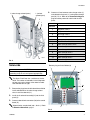
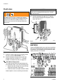
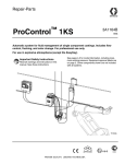
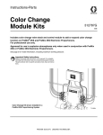
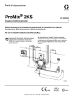
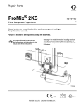
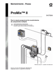
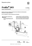
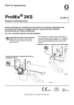
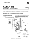
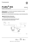
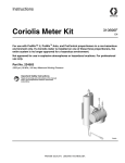
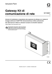
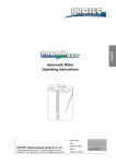
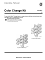
Instructions - Parts List
Color Change Kit
310656C
EN
For use with ProMix™ II proportioner, to change colors or distribute industrial paints and
coatings or fluids. For professional use only.
Important Safety Instructions
Read warnings in the ProMix™ II Operation
manual. See page 8 and 10 for part numbers
and maximum working pressures.
TI11668a
Low Pressure Color Change
TI11665a
High Pressure Color Change
Installation
Installation
WARNING
J10 J5 J3 J6 J4 J1
J9
To reduce the risk of serious injury, including skin
injection, relieve pressure before installing the kit.
Follow the Pressure Relief Procedure in the ProMix™ II Operation or Service manual.
Color Change Valves
J8
C
D
1. Relieve pressure as instructed in the ProMix™ II
Operation or Service manual.
TI4886a
FIG. 2
2. Close main air shutoff valve on air supply line and
on ProMix™ II.
6. Use screws (10) included with kit to mount the
3. Shut off ProMix™ II power.
bracket (9) to the color change stack (1). Use two
more screws (10) to mount color change stack (1)
to fluid panel wall (F), using existing screw holes.
FIG. 3.
4. Loosen the 4 screws (A), then remove the Smart
Fluid Panel cover (B). FIG. 1.
1
9
B
A
10
TI4658A-2
FIG. 1
TI15262A
F
5. Slide the panel (C) until its bottom slots (D) align
with the top screw holes and secure the box in
place with the 2 screws. FIG. 2.
2
Low Pressure Color Change Stack Shown
FIG. 3
310656C
Installation
L (color change solenoid ports)
L (solvent
solenoid port)
4. Connect air lines between color change valves (1)
and solenoid valve ports (L), routing them through
port (M). FIG. 4. Refer to the Pneumatic Diagram,
page 6 and the pneumatic label inside the fluid
panel.
F
1
Solenoid
Actuates
Standard
1
Dispense Valve A
2
Dispense Valve B
3
Air Purge Valve A
4
Solvent Purge Valve B
Optional
M
TI4885A
FIG. 4
Solenoids
5
Gun Flush Box Pilot Valve
6
Color Change Solvent Valve
7
Color Change Valve 1
8
Color Change Valve 2
9
Color Change Valve 3
10
Color Change Valve 4
11
Color Change Valve 5
12
Color Change Valve 6
Remove plug and install elbow (8)
K
CAUTION
To avoid damaging circuit board when servicing, wear
grounding strap on wrist and ground appropriately.
C
11
The Smart Fluid Panel has a minimum of 4 solenoids. The number of solenoids in the kit depends
on how many color change valves were included.
See solenoid table at right.
J8
1. Remove the plugs from the left solenoid manifold to
6
5
4
3
install solenoid #6 for the color change solvent
valve. Install the solenoid (11).
2. Install the kit solenoid assembly (H) into the fluid
panel (C).
2
1
3. Connect solenoid wire connector (J8) to the control
board (K).
12
11
10
9
8
H
7
TI4875
Solenoid wires are polarized (red +, black –). Refer
to Electrical Schematic, page 7.
5
FIG. 5
310656C
3
Installation
Fluid Lines
WARNING
To reduce the risk of injury, including skin injection,
you must install a shutoff valve (P) between each fluid
supply line and the fluid manifold assembly. FIG. 6.
Use the valves to shut off fluid during maintenance
and service.
CAUTION
Verify that all unused fluid ports on the color change
valve stack are plugged before operation. An open
port will leak fluid.
3. Connect component A supply line (T) from the
color change manifold to the component A flow
meter inlet (R). FIG. 7.
N
6
5
3
1
4
2
1
P
T
R
TI4810A
FIG. 7
EEPROM
FIG. 6
Orient the EEPROM (U25) so its notch lines up with the
notch (W) marked on the fluid control board and install it
in the board. The EEPROM leads may need to be bent
slightly inward to fit in the socket.
U25
W
1. Connect a solvent supply line to the color change
valve (N), marked “CC SOLVENT”. FIG. 7.
2. Connect component A supply lines to the color
change valve stack (1) inlets. FIG. 7. The color
number is marked on the valve air supply line.
Paint Recirculating System
The color change valves have two fluid ports for
each individual valve. If you are recirculating paint:
1. Remove the color change valve stack from the
fluid panel and mount it separately.
2. Plumb the valves in one port and out the other.
Another option is to use a tee fitting to recirculate.
FIG. 8
4
310656C
Service
Service
Reassemble Fluid Panel
1. Remove screws and slide the panel (C) back into
place.
2. Secure cover (B) with the 4 screws (A). FIG. 9.
C
See the following manuals to service color change
valves.
Manual
Description
312783
312782
Color Change Valve Stacks
Color Change Valves
B
A
TI4658A-2
FIG. 9
310656C
5
ProMix™ II Schematics
ProMix™ II Schematics
Pneumatic Diagram
C
GUN
FLUSH
BOX
3/8 AIR FILTER
MANUAL DRAIN
5 MICRON
PRESS
SWITCH
S
AIR
FLOW
SWITCH
IN
A B
A B
A B
A B
A B
A B
AIR EXHAUST MUFFLER
12 VDC
SOLENOID
12 VDC
SOLENOID
12 VDC
SOLENOID
12 VDC
SOLENOID
12 VDC
SOLENOID
12 VDC
SOLENOID
MANIFOLD
CC SOLVENT OPEN
5/32 TUBE
COLOR
CHANGE
VALVE
TO GUN FLUSH BOX PILOT
5/32 TUBE
SOLVENT
PURGE
VALVE
AIR
PURGE
VALVE
DISPENSE
VALVE
B
DISPENSE
VALVE
A
CHECK VALVE
X
1/4 TUBE
FLUSH AIR TO FLUID INLET
AIR SUPPLY
1/4 TUBE
TO MANIFOLD
A B
A B
A B
A B
A B
A B
AIR EXHAUST MUFFLER
12 VDC
SOLENOID
12 VDC
SOLENOID
12 VDC
SOLENOID
12 VDC
SOLENOID
12 VDC
SOLENOID
12 VDC
SOLENOID
MANIFOLD
5/32 TUBE
CC 6 OPEN
5/32 TUBE
CC 6 OPEN
5/32 TUBE
CC 6 OPEN
5/32 TUBE
CC 6 OPEN
5/32 TUBE
CC 6 OPEN
5/32 TUBE
CC 6 OPEN
COLOR
CHANGE
VALVE 2
COLOR
CHANGE
VALVE 3
COLOR
CHANGE
VALVE 4
COLOR
CHANGE
VALVE 5
COLOR
CHANGE
VALVE 6
TI4894A
COLOR
CHANGE
VALVE 1
ti4894a
310656C
6
OUT
A
A/A
SAFETY
SHUTOFF
TO GUN
AIR SUPPLY
P
FIG. 10
310656C
DISPLAY
117769
MEMBRANE
SWITCH
WITH
RIBBON
CABLE
15D223
J3
J2
1
2
3
4
5
6
7
8
9
10
11
12
13
14
15
16
17
18
19
20
1
2
3
4
5
6
7
8
9
10
11
DISPLAY
BOARD
248182
POWER
SUPPLY
AND
BARRIER
BOARD
248192
J5
J4
J5
J3
J1
OPEN
+24VDC
COMMON
+
-
WARNING
PRINTER
CONNECTOR
9-PIN D-SUB
119060
GRACO SHELL
COMMUNICATIONS
RJ12 CONNECTOR
15D255
POWER
ROCKER
SWITCH
116320
GND LUG
CABLE
15D320
CABLE
234453
1
2
1A
1B
2A
2B
1
2
3
TERMINAL 1
2
BLOCK
3
114095
FO IN
FO OUT
+12VDC I/S
COM
SHIELD
HARNESS
15D647
J10
L1 85-250 VAC
L2
GND
1
2
3
FLUID
PANEL
CONTROL
BOARD
248163
1
2
3
4
12
11
10
9
8
7
6
5
4
3
2
1
12
11
10
9
8
7
6
5
4
3
2
1
1
2
3
4
5
1
2
3
4
5
6
7
8
J1
J9
J8
J5
J3
SIG
COM
SIG
COM
BLACK
RED
BLACK
RED
BLACK
RED
BLACK
RED
BLACK
RED
BLACK
RED
BLACK
RED
BLACK
RED
BLACK
RED
BLACK
RED
BLACK
RED
BLACK
RED
MIX A
MIX B
FLUSH A
FLUSH B
G.F.B.
CC SOL
COLOR 1
COLOR 2
COLOR 3
COLOR 4
COLOR 5
J3
MEMBRANE
SWITCH
WITH
RIBBON
CABLE
15D187
12 VDC
SOLENOID
117356
12 VDC
SOLENOID
117356
1
1 OPERATOR 2
3
2 STATION
4
3 BOARD
5
4
6
248124
5
7
8
9
10
239716
FLOW METER B
239716
FLOW METER A
ti4895a
AIR FLOW SWITCH-119159
PRESSURE SWITCH-513937
MANIFOLD
MANIFOLD
J4
COLOR 6
CABLE
241799
CABLE
241799
B (GRN)
A (WHT)
PWR (RED)
COM (BLK)
SHIELD
HARNESS CABLE
15D648
234448
PWR (RED)
COM (BLACK)
SIG (WHITE)
SHIELD
PWR (RED)
COM (BLACK)
SIG (WHITE)
SHIELD
FLUID PANEL CONTROL BOX
HAZARDOUS AREA
Do not install equipment approved only for non-hazardous location in a hazardous area. Substitution of components may impair intrinsic safety.
FO OUT
FO IN
1
2
3
4
5
6
7
8
9
1
2
3
4
5
6
ALARM
15D568
+12VDC I/S (WHITE)
COM (BLACK)
SHIELD
HARNESS
15D649
+24VDC
OPEN
COMMON
L1 85-250 VAC
OPEN
L2 ACC POWER OUTPUT
L1
L2
GND
J6-RS 232
1
TX (WHITE)
2
RX (BLACK)
3
CMN (RED)
4
TX
5
OPEN
6
CMN
1
2
3
4
1
2
3
1
2
3
1
2
1
2
3
OPERATOR INTERFACE
1
2
3
NON-HAZARDOUS AREA
ProMix™ II Schematics
Electrical Schematic
FIG. 11
TI4895A
7
Parts
Parts
Low Pressure Color Change Kits
300 psi (2.1 MPa, 21 bar) Maximum Working Pressure
Part No. 234568, Series B, 2 color
Part No. 234569, Series B, 4 color
Part No. 234570, Series B, 6 color
Ref.
No.
1
2
3
4
5†*
6†*
7†
8
9†
10†
11
12
13
†
*
8
Part No. Description
Qty
15V812 VALVE STACK, low pressure; for
1
234568; see manual 312783
15V813 VALVE STACK, low pressure; for
1
234569; see manual 312783
256293 VALVE STACK, low pressure; for
1
234570; see manual 312783
253502 SOLENOID STACK; for 234568
1
253503 SOLENOID STACK; for 234569
1
253504 SOLENOID STACK; for 234570
1
24N345 HOSE; ptfe; 1/4 npsm(fbe); 1/4 in.
1
(6 mm) ID; 1.5 ft (0.46 m)
2
114669 SCREW, machine; to mount solenoid manifold to electrical box; M5 x
0.8 x 10
n/a
TUBE, nylon; 1/4 in. (6 mm) OD;
1
0.5 ft (15 cm)
598095 TUBE, nylon; 5/32 in. (4 mm) OD;
1
13 ft (3.96 m)
15D826 EEPROM, with software
1
166866 ELBOW (see FIG. 5 on page 3);
1
1/4-18 npt (m x f)
15U927 BRACKET, color change (see FIG.
1
3 on page 2)
C19798 SCREW, cap, socket-hd; for mount- 4
ing bracket (see FIG. 3 on page 2);
1/4-20 x 3/8 in. (10 mm)
117356 SOLENOID, 12 VDC (IS); see FIG.
1
5 on page 3 for location
114263 CONNECTOR; 1/8 npt x 5/32 in. (4
1
mm) OD tube
112512 FERRULE, wire, orange
2
Not shown.
Order length needed.
310656C
Parts
6
5
4
3
2
1
Connect solenoid air
supply tube (5) here
6
5
4
3
2
1
2
12 BLACK
END
1 RED
START
12
1
12
11
4
TI4864b
13
253504 Solenoid Stack Shown
(for Kit 234570)
1
15V813 Valve Stack Shown
(for Kit 234569)
TI11668a
Connect valve open tube (6) here
Connect hose (3) here
Low Pressure Color Change
310656C
9
Parts
High Pressure Color Change Kits
3000 psi (21 MPa, 207 bar) Maximum Working Pressure
Part No. 234572, Series B, 2 color
Part No. 234573, Series B, 4 color
Part No. 234574, Series B, 6 color
Ref.
No.
1
2
3
4
5†*
6†*
7†
8
9†
10†
11
12
13
Part No. Description
Qty
15V816 VALVE STACK, high pressure; for
1
234572; see manual 312783
15V817 VALVE STACK, high pressure; for
1
234573; see manual 312783
256342 VALVE STACK, low pressure; for
1
234574; see manual 312783
253502 SOLENOID STACK; for 234568
1
253503 SOLENOID STACK; for 234569
1
253504 SOLENOID STACK; for 234570
1
24N345 HOSE; ptfe; 1/4 npsm(fbe); 1/4 in.
1
(6 mm) ID; 1.5 ft (0.46 m)
114669 SCREW, machine; to mount sole2
noid manifold to electrical box; M5 x
0.8 x 10
n/a
TUBE, nylon; 1/4 in. (6 mm) OD;
1
0.5 ft (15 cm)
598095 TUBE, nylon; 5/32 in. (4 mm) OD;
1
13 ft (3.96 m)
15D826 EEPROM, with software
1
166866 ELBOW (see FIG. 5 on page 3);
1
1/4-18 npt (m x f)
15U927 BRACKET, color change (see FIG.
1
3 on page 2)
C19798 SCREW, cap, socket-hd; for mount- 4
ing bracket (see FIG. 3 on page 2);
1/4-20 x 3/8 in. (10 mm)
117356 SOLENOID, 12 VDC (IS); see FIG.
1
5 on page 3 for location
114263 CONNECTOR; 1/8 npt x 5/32 in. (4
1
mm) OD tube
112512 FERRULE, wire, orange
2
*
Order length needed.
†
Not shown.
10
310656C
Parts
6
5
4
3
2
1
Connect solenoid air
supply tube (5) here
6
5
4
3
2
1
2
12 BLACK
END
1 RED
START
12
1
12
11
TI4864b
4
253504 Solenoid Stack Shown
(for Kit 234574)
13
1
Connect valve open tube (6) here
15V817 Valve Stack Shown
(for Kit 234573)
TI11665a
Connect hose (3) here
High Pressure Color Change
310656C
11
Graco Standard Warranty
Graco warrants all equipment referenced in this document which is manufactured by Graco and bearing its name to be free from defects in
material and workmanship on the date of sale to the original purchaser for use. With the exception of any special, extended, or limited warranty
published by Graco, Graco will, for a period of twelve months from the date of sale, repair or replace any part of the equipment determined by
Graco to be defective. This warranty applies only when the equipment is installed, operated and maintained in accordance with Graco’s written
recommendations.
This warranty does not cover, and Graco shall not be liable for general wear and tear, or any malfunction, damage or wear caused by faulty
installation, misapplication, abrasion, corrosion, inadequate or improper maintenance, negligence, accident, tampering, or substitution of
non-Graco component parts. Nor shall Graco be liable for malfunction, damage or wear caused by the incompatibility of Graco equipment with
structures, accessories, equipment or materials not supplied by Graco, or the improper design, manufacture, installation, operation or
maintenance of structures, accessories, equipment or materials not supplied by Graco.
This warranty is conditioned upon the prepaid return of the equipment claimed to be defective to an authorized Graco distributor for verification of
the claimed defect. If the claimed defect is verified, Graco will repair or replace free of charge any defective parts. The equipment will be returned
to the original purchaser transportation prepaid. If inspection of the equipment does not disclose any defect in material or workmanship, repairs will
be made at a reasonable charge, which charges may include the costs of parts, labor, and transportation.
THIS WARRANTY IS EXCLUSIVE, AND IS IN LIEU OF ANY OTHER WARRANTIES, EXPRESS OR IMPLIED, INCLUDING BUT NOT LIMITED
TO WARRANTY OF MERCHANTABILITY OR WARRANTY OF FITNESS FOR A PARTICULAR PURPOSE.
Graco’s sole obligation and buyer’s sole remedy for any breach of warranty shall be as set forth above. The buyer agrees that no other remedy
(including, but not limited to, incidental or consequential damages for lost profits, lost sales, injury to person or property, or any other incidental or
consequential loss) shall be available. Any action for breach of warranty must be brought within two (2) years of the date of sale.
GRACO MAKES NO WARRANTY, AND DISCLAIMS ALL IMPLIED WARRANTIES OF MERCHANTABILITY AND FITNESS FOR A
PARTICULAR PURPOSE, IN CONNECTION WITH ACCESSORIES, EQUIPMENT, MATERIALS OR COMPONENTS SOLD BUT NOT
MANUFACTURED BY GRACO. These items sold, but not manufactured by Graco (such as electric motors, switches, hose, etc.), are subject to
the warranty, if any, of their manufacturer. Graco will provide purchaser with reasonable assistance in making any claim for breach of these
warranties.
In no event will Graco be liable for indirect, incidental, special or consequential damages resulting from Graco supplying equipment hereunder, or
the furnishing, performance, or use of any products or other goods sold hereto, whether due to a breach of contract, breach of warranty, the
negligence of Graco, or otherwise.
FOR GRACO CANADA CUSTOMERS
The Parties acknowledge that they have required that the present document, as well as all documents, notices and legal proceedings entered into,
given or instituted pursuant hereto or relating directly or indirectly hereto, be drawn up in English. Les parties reconnaissent avoir convenu que la
rédaction du présente document sera en Anglais, ainsi que tous documents, avis et procédures judiciaires exécutés, donnés ou intentés, à la suite
de ou en rapport, directement ou indirectement, avec les procédures concernées.
Graco Information
For the latest information about Graco products, visit www.graco.com.
TO PLACE AN ORDER, contact your Graco distributor or call to identify the nearest distributor.
Phone: 612-623-6921 or Toll Free: 1-800-328-0211, Fax: 612-378-3505
All written and visual data contained in this document reflects the latest product information available at the time of publication.
Graco reserves the right to make changes at any time without notice.
Original instructions. This manual contains English. MM 310656
Graco Headquarters: Minneapolis
International Offices: Belgium, China, Japan, Korea
GRACO INC. AND SUBSIDIARIES • P.O. BOX 1441 • MINNEAPOLIS, MN 55440-1441 • USA
Copyright 2004, Graco Inc. All Graco manufacturing locations are registered to ISO 9001.
www.graco.com
Revised September 2012