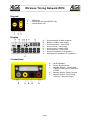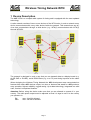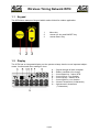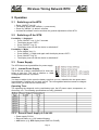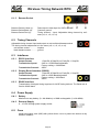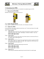
1
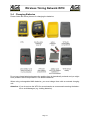
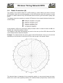
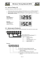
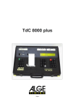
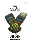
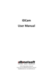
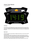
Version-E140130 Manual Wireless Timing Network WTN Important Information General Before using your ALGE-TIMING device read the complete manual carefully. It is part of the device and contains important information about installation, safety and its intended use. This manual cannot cover all conceivable applications. For further information or in case of problems that are mentioned not at all or not sufficiently detailed, please contact your ALGE-TIMING representative. You can find contact details on our homepage www.alge-timing.com Safety Apart from the information of this manual all general safety and accident prevention regulations of the legislator must be taken into account. The device must only be used by trained persons. The setting-up and installation must only be exe cuted according to the manufacturer’s data. Intended Use The device must only be used for its intended applications. Technical modifications and any misuse are prohibited because of the risks involved! ALGE-TIMING is not liable for damages that are caused by improper use or incorrect operation. Power supply The stated voltage on the type plate must correspond to voltage of the power source. Check all con nections and plugs before usage. Damaged connection wires must be replaced immediately by an authorized electrician. The device must only be connected to an electric supply that has been installed by an electrician according to IEC 60364-1. Never touch the mains plug with wet hands! Never touch live parts! Cleaning Please clean the outside of the device only with a smooth cloth. Detergents can cause damage. Never submerge in water, never open or clean with wet cloth. The cleaning must not be carried out by hose or high-pressure (risk of short circuits or other damage). Liability Limitations All technical information, data and information for installation and operation correspond to the latest status at time of printing and are made in all conscience considering our past experience and knowledge. Information, pictures and description do not entitle to base any claims. The manufacturer is not liable for damage due to failure to observe the manual, improper use, incorrect repairs, technical modi fications, use of unauthorized spare parts. Translations are made in all conscience. We assume no lia bility for translation mistakes, even if the translation is carried out by us or on our behalf. Disposal If a label is placed on the device showing a crossed out dustbin on wheels (see drawing), the European directive 2002/96/EG applies for this device. Please get informed about the applicable regulations for separate collection of electrical and electronical waste in your country and do not dispose of the old devices as household waste. Correct disposal of old equipment protects the environment and humans against negative consequences! Operating ranges and interferences The ALGE WTN operates in 4.2 GHz frequency band, the same as WLAN. This is also used by other services. The operating range as well as the operation may be disturbed by devices working at the same or neighboring frequencies. Copyright by ALGE-TIMING GmbH All rights reserved. Any duplication, either in full or in part, requires the prior written consent of the copyright holder. Page 2 Wireless Timing Network WTN Declaration of Conformity We hereby declare that the following product complies with the below stated standards. All components used by us are CE certified by their producer and are not modified by ALGE-TIMING GmbH. We, ALGE-TIMING GmbH Rotkreuzstrasse 39 A-6890 Lustenau declare in sole responsibility that the radio receiver Wireless Timing Network WTN complies with the following standards/normative documents and in case of intended use complies with the basic requirements of R&TTE 1999/5/EC: Telecommunication (TC)terminal device Short Range Device Applied harmonized standards… EN 60950-1:2006+A11:2009+A1:2010+A12:2011 EMC: EN301 489-17 v2.1.1. (2009-05) EN 300 328 v1.7.1 (2006-10) EN 55022 : 2010 / AC : 2011 EN 55024 : 2010 EN 61000 3-2:2006 EN 61000 3-3:2008 Additional information: The product complies with the low voltage directive 73/23/EEC and EMC directive 2004/108EG and carries the CE sign. ALGE-TIMING GmbH Lustenau, 12.03.2012 Albert Vetter (CEO) Page 3 Wireless Timing Network WTN Keypad 1.........MENU-key 2.........<arrow up> key and ON/OFF-key 3.........<arrow down> key Display A......Signal strength of radio reception B......Battery condition (four levels) C......Arrow down key = slave WTN D......Arrow left key = no function E......Arrow up key = master WTN F......Arrow right key = no function G......Numeric characters (4 characters) H......Alphanumeric characters (7 characters) Connections a.......ALGE Multiport b.......Power Supply Socket c.......Banana Socket – Yellow: Data output or Data input for GAZ and D-LINE d.......Banana Socket - Black: Ground e.......Banana Socket - Red: Timing Channel – input and output Page 4 Wireless Timing Network WTN Table of Content 1 Device Description............................................................................................................. 7 1.1 Keypad.............................................................................................................................. 8 1.2 Display.............................................................................................................................. 8 2 Operation............................................................................................................................ 9 2.1 Switching on the WTN.......................................................................................................9 2.2 Switching off the WTN.......................................................................................................9 2.3 Power Supply.................................................................................................................... 9 2.3.1 Internal Power Supply....................................................................................................................................... 9 2.3.2 External Power Supply +8 to 24 VDC...............................................................................................................9 2.4 Changing Batteries.......................................................................................................... 10 2.5 Radio Connection (A)......................................................................................................11 2.6 Battery Indicator (B)........................................................................................................ 13 2.7 Master and Slave Function (C and E)..............................................................................13 2.8 Numeric Display (G)........................................................................................................14 2.9 Alphanumeric Display (H)................................................................................................14 3 Menu.................................................................................................................................. 15 3.1 Operation of the Main Menu............................................................................................15 3.1.1 Team Number <TEAM>.................................................................................................................................. 15 3.1.2 Channel for Banana Socket <BANANA>........................................................................................................16 3.1.3 Info Display..................................................................................................................................................... 17 3.1.4 Switching off <OFF>....................................................................................................................................... 17 3.2 Submenu <SETTINGS>..................................................................................................17 3.2.1 Power Output <POWER>............................................................................................................................... 17 3.2.2 Adjustment of used Battery Type <ALKALI> or <NIMH>................................................................................18 3.2.3 Radio Frequency <CHANNEL>...................................................................................................................... 18 3.2.4 Baud Rate for Display Boards <GAZ>............................................................................................................18 3.2.5 Baud Rate for RS232-Interface <RS232>......................................................................................................18 3.2.6 Timing Impulse Edge <EDGE>....................................................................................................................... 19 3.2.7 Adjustment of the Delay Time of all Timing Channels<DELAY T>.................................................................20 3.2.8 Pulse Hold Message <P HOLD>.................................................................................................................... 21 3.2.9 Adjustment of the Address fort he Infodisplay <INFO AD>............................................................................21 3.2.10 Factory Settings <DEFAULT>...................................................................................................................... 22 3.2.11 Connection to PC for Firmware-Update <PC-UPD>.....................................................................................22 3.2.12 Transmit New Firmware to Other WTN Devices <RF-UPD>........................................................................23 3.2.13 Receive Signal Strength Indicator <rSSI>....................................................................................................23 4 Synchronization of WTN Devices...................................................................................23 5 Connection of External Devices......................................................................................24 5.1 Timing Devices................................................................................................................ 24 5.1.1 TdC 8001 and TdC8000plus...........................................................................................................................24 5.1.2 Timy and Timy2.............................................................................................................................................. 24 5.2 Impulse Devices.............................................................................................................. 26 5.3 Display Board.................................................................................................................. 26 5.4 PC with RS232 Interface.................................................................................................27 6 Technical Data.................................................................................................................. 28 6.1 Connections.................................................................................................................... 28 6.1.1 ALGE Multiport (a).......................................................................................................................................... 28 6.1.2 Power Supply (b)............................................................................................................................................ 28 6.1.3 Banana Socket............................................................................................................................................... 29 6.2 Timing Channels............................................................................................................. 29 6.3 Interfaces........................................................................................................................ 29 6.3.1 RS232 Interface.............................................................................................................................................. 29 6.3.2 Display Board Interface (RS232)....................................................................................................................29 6.3.3 RS485 Interface.............................................................................................................................................. 29 6.4 Power Supply.................................................................................................................. 29 6.4.1 Battery 29 6.4.2 External Supply............................................................................................................................................... 29 Page 5 Wireless Timing Network WTN 6.5 Case................................................................................................................................ 29 7 Accessory for WTN.......................................................................................................... 30 7.1 Bracket for WTN SPB1....................................................................................................30 7.2 Power Supply PS12A......................................................................................................30 7.3 Cables for WTN............................................................................................................... 30 7.3.1 Cable 280-XX................................................................................................................................................. 30 7.3.2 Cable 283-02.................................................................................................................................................. 30 7.3.3 Cable 284-02.................................................................................................................................................. 30 7.3.4 Cable 000-XX................................................................................................................................................. 30 7.3.5 Cable 037-10.................................................................................................................................................. 30 Page 6 Wireless Timing Network WTN 1 Device Description The ALGE WTN is a compact radio system for timing and is equipped with the most updated technology. A radio network consists of two or more devices of the WTN series. In such a network every device communicates with every other device inside the network. This means there are devices that communicate through a third device (e.g. WTN(3) communicates with WTN(7) through WTN(5)). The network is designed in such a way that you can transmit data to a display board (e.g. ALGE GAZ or D-LINE), serial RS232 data (e.g. to a PC) and timing impulses at the same time. When designing the Wireless Timing Network the ALGE development team concentrated on features that make ALGE devices unique, but also on features that stand for ALGE products: easy operation, highest reliability, rugged casing. Up-to-date technology, integrated in a solid case, results in exceptional features. Attention: Before using the device make sure that you are allowed to operate it in your country. The radio power output must be adjusted so that it is legal to use it in the country you operate it in. EU: USA: max. 10 mW is allowed max. 100 mW is allowed Page 7 Wireless Timing Network WTN 1.1 Keypad The WTN has a waterproof keypad which makes it ideal for outdoor application. 1 2 3 1.2 Menu-key <arrow up> key and ON/OFF-key <arrow down> key Display The WTN has an integrated display so the operator always has the most important adjustments, functions and menu settings in view. A......Signal strength of radio reception B......Battery condition (four levels) C......Arrow down key = slave WTN D......Arrow left key = no function E......Arrow up key = master WTN F......Arrow right key = no function G......Numeric characters (4 characters) H......Alphanumeric characters (7 characters) Page 8 Wireless Timing Network WTN 2 Operation 2.1 • • • • 2.2 Switching on the WTN Press „ON/OFF“ key (2). The display shows <PR. MENU> (= press menu). Press key „MENU“ (1) within 3 seconds. It shows the software version and then the general adjustments of the WTN. Switching off the WTN Possibility 1 - Keyboard • Press „ON/OFF“ key (1) for 5 seconds. • The display shows <OFF>. • Press „ON/OFF“ key (2). • The display turns off and the device is switched off. Possibility 2 - Menu • Press „MENU“ key (1). • Press „MENU“ (1) again and again until the display shows <OFF>. • Press „ON/OFF“ key (2). • The display turns off and the device is switched off. 2.3 Power Supply The WTN has several possibilities for power supply: 2.3.1 Internal Power Supply The WTN has a battery compartment for three batteries of type AA. The use of alkaline or NiMh rechargeable batteries is possible. Attention: You have to adjust in the menu the battery type that you use, otherwise the low power warning and battery condition will not work correct. The rechargeable batteries cannot be charged in the WTN, you must use an external unit. Operating Time: The operating time depends on the used battery type, the HF power output, temperature, radio activity, etc. The following specifications are only guidelines. 2.3.2 External Power Supply +8 to 24 VDC • Power supply PS12A • External battery e.g. 12V lead acid battery • ALGE device (e.g. ALGE display board GAZ4 or D-LINE) Page 9 Wireless Timing Network WTN 2.4 Changing Batteries Please follow the below pictures for changing the batteries: Do not use cheap batteries because the working time is dramatically reduced and you might have problems at low temperatures. Use alkaline batteries. When using rechargeable NiMh batteries, you must charge them with an external charging unit. Attention: If you do not use the WTN for several weeks we recommend removing the batteries to avoid damages (e.g. leaking batteries). Page 10 Wireless Timing Network WTN 2.5 Radio Connection (A) The quality of the network status for a WTN system is crucial. Before you start to use the WTN network check the connection quality of every WTN device used in the system. In order to work in a stable network every WTN should show at least a good connection quality (two bars). The display shows the reception to another WTN device in the network that has the best connection quality. In the submenu <rSSI> the connection quality is shown in dB. If a value of below -60 dB is indicated, the connection quality is critical. The radiation of the radio can depend very much on the set up of the WTN. Move the WTN until it shows the best network reception. Example: The sketch shows the power output of the WTN antenna. Here you can see that depending on the direction to the other WTN you have a high or low power output. The selected team is important for the connection quality. In case several teams are operated next to each other (spatial proximity) the selected teams (frequencies) should not be Page 11 Wireless Timing Network WTN side by side within the frequency band (see picture below). For example using teams 1S and 2S should be avoided as frequencies situated next to each other could influence one another in a negative way. The picture above shows the frequencies of the WTN (yellow and red bars) and of other users in the same frequency band. The more users operate the same frequency or a similar frequency the more difficult it is to guarantee a stable connection. Page 12 Wireless Timing Network WTN 2.6 Battery Indicator (B) The WTN has a battery indicator that constantly keeps you informed about the battery condition as follows: Attention: It is essential to set the correct battery type in the menu so that the displayed battery condition is accurate. For charging rechargeable NiMh batteries you have to use an external charging unit. 2.7 Master and Slave Function (C and E) Each WTN network has a master WTN (E) that synchronizes the other WTN devices (C) (slaves). If the master WTN disappears in a network (e.g. because of an empty battery) the remaining WTN devices select a new master. If one WTN sends an impulse during this period this impulse is lost (only the first impulse). As soon as the synchronization is finished the system works normal again. Master of the WTN Network (E) The master is marked with the arrow up (E). Within a network there is only one master. The master is always the WTN with lowest MAC address in the network. Slaves in the WTN Network (C) Slaves are marked with the arrow down (C). Page 13 Wireless Timing Network WTN 2.8 Numeric Display (G) It shows the frequency and the team number. • • • The first two figures show the adjusted radio frequency (up to 16 different channels). The third figure shows the team number (1, 2, 3, 4, 5, 6, 7, 8, 9, A, b, C, d, E, F) The fourth figure shows, if the team number is used in single mode („S“ for single) or sharing mode („A“ for all). Example: Radio Channel 12 Team Number 9 Single Team (S) Example: Radio Channel 15 Team Number C Sharing Team (A) 2.9 Alphanumeric Display (H) The alphanumeric display shows the following information if not used for the menu mode: Amount of neighbor devices Amount of devices in the team (including this device) Amount of total devices in connected network Information blinks only short 0 to 4.............impulse on channel C ...................Delayed channel times S ...................serial data G...................data for display board V ...................Version conflict within the Network P ...................Pulse hold message M...................Update- or Settings packet R ...................RS485 Command Example: Page 14 Wireless Timing Network WTN 3 Menu The menu allows configuring the Wireless Timing Network WTN. The WTN has a main menu (to adjust the most important functions) and a submenu (to adjust parameters that are not often used or that are in most cases used with factory setting). 3.1 Operation of the Main Menu Select the main menu by pressing the key „MENU“ (1). By pressing the key „MENU“ (1) again it is possible to browse the main menu. In order to make changes in the selected menu use the arrow keys (2 or 3). Always the last indicated value is set when switching to another menu or leaving the menus. Menu Order: • TEAM • BANANA • INFO • OFF 3.1.1 Team Number Channel of Banana Socket Data Info Display Turn WTN off factory setting = S1 factory setting = C0 no factory setting no factory setting Team Number <TEAM> This function is to select the team number of a WTN system. You can select between 15 team numbers. There are 9 single teams (S) and 6 common teams (A). Separate Teams <S> = SINGLE Used for completely independent both networks work in this mode each other. 1:S 2:S 7:S 8:S networks. If you operate two networks next to each other on different frequencies and do not communicate among 3:S 9:S 4:S Joint Teams <A> = ALL Page 15 5:S 6:S Wireless Timing Network WTN Used for networks that work independently next to each other. If different A teams with the same radio channel are operated, the other A teams can be used for data transmission. The data of the other team however is not used (e.g. for two show jumping grounds that are next to each other). A:A b:A C:A d:A E:A F:A 3.1.2 Channel for Banana Socket <BANANA> For timing you can choose 5 adjustable timing channels for the banana sockets. The factory setting: C0 Selection: C0, C1, C2, C3 or C4 For ALGE-TIMING the following timing channels are used: C0 = Start Channel C1 = Finish Channel C2 = Intermediate Time 1 C3 = Intermediate Time 2 or Start Channel 2 C4 = Intermediate Time 3 or Finish Channel 2 Page 16 Wireless Timing Network WTN 3.1.3 Info Display Here, you can see data that you send to the display board. In this mode the WTN is a small info system. Due to the limited display space it shows the bib number only with two digits and the time in minutes, seconds and 1/10 seconds. 3.1.4 Switching off <OFF> If you press in this menu the „On/Off“ key (2) the WTN will switch off. 3.2 Submenu <SETTINGS> You select the submenu <SETTINGS> by pressing the key „MENU“ (1) for about 5 seconds. By pressing the key „MENU“ (1) again it is possible to browse the main menu. Use the arrow keys (2 or 3) to make changes in the selected menu. Always the last indicated value is set when switching to another menu or leaving the menus. Menu Adjustments: • Setting • RF PWR • ALKALI or NIMH • CHANNEL • GAZ • RS232 • EDGE • DELAY T • P HOLD • INFO AD • DEFAULT • PC-UPD • RF-UPD • rSSI 3.2.1 info that you entered the <SETTINGS> menu adjustment of the radio power output (10 to 100 mW) adjustment of the used battery type „ALKALI“ or „NIMH“ adjustment of the radio frequency baud rate used for the display board data transmission (RS232) baud rate for the RS232 interface adjustment of the edges of the timing channels adjustment of the delay times of all timing channels Pulse hold message (if a photocell is not aligned) adjustment of the address for the info display load the factory settings switching on or off the update mode from a PC send updates to other WTN devices in the network by radio shows the network reception of this WTN Power Output <POWER> There are different rules about the allowed power output of this radio band. Depending on the country in which the WTN is used you have to adjust the power. For EU countries 10 mW power output is allowed (max. reach about 350 m at free sight). • • • • 10 mW (Europe) 25 mW 50 mW 100 mW (USA) Please note the country specific maximal power output and do not use a stronger output as allowed. ALGE-TIMING has set the lowest output with 10 mW as default setting. Using this radio with a power output that is too high violates the law and you might be fined. Do not use the WTN in countries that do not allow operating the WTN with the selected frequency. Page 17 Wireless Timing Network WTN 3.2.2 Adjustment of used Battery Type <ALKALI> or <NIMH> You can operate the WTN with Alkaline batteries or NiMh-rechargeable batteries. In order to have an accurate battery indication you must adjust the used battery type in this menu. The factory setting is <ALKALI> Alkaline disposable battery: NiMh rechargeable battery: < ALKALI> factory setting (default) <NIMH> You cannot charge NiMh rechargeable batteries inside the WTN. To charge them use an external charging device. 3.2.3 Radio Frequency <CHANNEL> You can adjust 16 different radio frequencies. Please note, that e.g. the photocell PR1a-W does not allow adjusting all 16 frequencies. We recommend not to use this function but to adjust the frequency in the main menu with the team number. If you change a team number it automatically changes the <CHANNEL>. 3.2.4 Baud Rate for Display Boards <GAZ> You can select the following RS232 baud rates for the display board interface (banana socket yellow (c) and black (d)): 2400 Baud .........factory setting (default) 4800 Baud 9600 Baud 19200 Baud OFF....................display board data transmission for this device off Attention: If you change the baud rate it is changed for all devices that are in the same network at that moment. If you set “OFF” it does not change other WTN in the network. 3.2.5 Baud Rate for RS232-Interface <RS232> You can select the following RS232 baud rates for the RS232 interface (e.g. connection to PC) for the Multiport (a): 2400 Baud 4800 Baud 9600 Baud .........factory setting (default) 19200 Baud 38400 Baud 57600 Baud 115200 Baud Attention: If you change the baud rate it is changed for all devices that are in the same network at that moment. Page 18 Wireless Timing Network WTN 3.2.6 Timing Impulse Edge <EDGE> You can adjust at the WTN if a timing impulse has an output of the falling edge <EDGE1> or of both edges <EDGE2). EDGE1 = falling edge EDGE2 = falling and rising edge Attention: A timing impulse that is sent through the WTN is always 0.1 seconds delayed (+/-0.0001 s). Example for EDGE1: In the following diagram is dt the delay time for the falling edge (blue). Example for EDGE2: In the following diagram is dt the delay time of the falling edge (blue) and dt the delay time of the rising edge (red). Factory Setting: EDGE1 Page 19 Wireless Timing Network WTN 3.2.7 Adjustment of the Delay Time of all Timing Channels<DELAY T> The variable delay prevent generating double impulses and loosing impulses. The delay and block times can be changed in the menu. Delay Time After triggering an impulse, further impulses of the same impulse channel are disabled for the duration of the delay time. Base settings: C0, C1, C2, C3 and C4 = 0.1 s Diagram of Delay and Block Time: t..........timing channel triggered 1...........timing channel is triggered – valid time is saved – block time starts 2...........end of impulse – delay time starts 3...........timing channel is triggered within the delay time – no impulse triggering 4...........end of impulse – delay time restarts 5...........timing channel is triggered within the block time – invalid time is saved but not printed 6...........end of impulse – delay time starts 7...........timing channel is triggered – valid time is saved – block time starts Factory Setting: 0.1 s Page 20 Wireless Timing Network WTN 3.2.8 Pulse Hold Message <P HOLD> This new feature sends a periodical message to the Timing device if a photocell is not aligned. This Message can be set up for all timing channels separately. Possible values are from 0 to 59,9 seconds. 0 means there is no message sent (for example: startgates) Standard value is 5 Seconds. 3.2.9 Adjustment of the Address fort he Infodisplay <INFO AD> It is possible to adjust the address for the data that you want to show on the info display of the WTN (see 3.1.3 Info Display). A...........Data of all addresses are shown 0...........Data without address are shown 1...........Data of address 1 are shown 2...........Data of address 2 are shown … 25.........Data of address 25 are shown 26.........Data of address 26 are shown Factory Setting: 0 Page 21 Wireless Timing Network WTN 3.2.10 Factory Settings <DEFAULT> If you activate <Default> by pressing the ON/OFF key (2), you reset the WTN and load the factory settings. Team Number Timing Channel Power Output of Radio Battery Type Baud rate for display board Baud rate for RS232 interface Edge adjustment for timing Delay time for channels Pulse hold message Address for Info Display <TEAM> <BANANA> <RF PWR> <ALKALI> <GAZ> <RS232> <EDGE1> <DELAY T> <P HOLD> <INFO AD> S1 C0 10 mW Alkaline disposable batteries 2400 Baud 9600 Baud EDGE1 for all channels 0.1 s for all channels 5.0 s 0 (no address) 3.2.11 Connection to PC for Firmware-Update <PC-UPD> If you wan to make a firmware update to the WTN you will need a Cable 283-02 and a serial interface at your PC. First connect your WTN to the PC and the go to the <SETTINGS> menu. You get into this menu by pressing the MENU button for 5 seconds. Then press the MENU button several times until you see „PC-UPD“ in the display. Now press the arrow up until you can see „ON“ in the display. Now start the Installationsmanager from your Alge USB Stick. Go to „WTN“., choose the connected Com Port. Click to the desired update variant (Internet or USB Stick). After the update is finished the WTN makes a restart automatically. Note: It can happen that the update set standard values to the WTN settings. Page 22 Wireless Timing Network WTN 3.2.12 Transmit New Firmware to Other WTN Devices <RF-UPD> When you have several WTN-devices in a network you can make the update of the firmware on one device through RS232 from a PC. This device can now update the firmware of all other devices in the same network. • • • • • • Update the WTN as described in 3.2.10 Switch all WTN-devices on that you want to update from the WTN with the new firmware and check that they all use the same team. Start the update as described below in the device with the updated firmware. For the devices that you want to update you have not to make any further adjustment. Go into the submenu <SETTINGS> by pressing continuous the key „MENU“ (1) for about. 5 seconds. Press „MENU“ (1) to move through the menu until it shows <RF-UPD>. Press key „ON/OFF“ (2) to start the update. 3.2.13 Receive Signal Strength Indicator <rSSI> In the submenu <rSSI> the connection quality is indicated in dB. If a value below -58 dB the connection is shown the quality is critical. 4 Synchronization of WTN Devices All WTN devices in a network must synchronize each other and determine a master. This synchronization is effected automatically. A new participant in the network always causes a new synchronization. Until the moment a new synchronization of the network is completed, no timing impulses can be transmitted. The timing impulse is stored in the device and is transmitted as soon as the network is synchronized together with an identification of the delay. Current ALGE-TIMING devices (e.g. Timy and TdC 8001) recalculate the original time of the impulse if adjusted so. Master of a Network(E): At the Master the arrow show up (E). There is only one Master in the network. The Master is the device that synchronizes the others. Page 23 Wireless Timing Network WTN 5 Connection of External Devices 5.1 Timing Devices Please be careful if you have more than one timing device in your WTN network. Each timing device that is connected with cable 280 outputs the data for display boards automatically. If a display boards receives the data from two timing devices a data collision is caused. Please take care that only one timing device sends display board data. Deactivate the output to the display board in all other WTN. 5.1.1 TdC 8001 and TdC8000plus Use cable 280-XX (XX stands for the cable length in meters) to connect a timing device TdC8001 or TdC8000plus with a WTN. This 25-pole wire is used for transmitting the following: • RS232 data • Data for display board(s) • Timing impulse (channel 0 to 4) • Delayed timing impulse through RS485 Delayed Impulse Transmission: The delayed impulse transmission occurs in case a WTN in the network does not receive a timing impulse. This causes that the impulse including delay time is send via RS485 to the missing device until a receipt confirmation is returned. The delayed timing impulse is sent for 90 seconds. If within these 90 seconds the transmitter receives no receipt confirmation the transmission is stopped and the WTN that did not answer is eliminated in the network. In order to activate such delayed timing impulses it is necessary to execute certain adjustments in the TdC8001 or TdC8000plus. 5.1.2 Timy and Timy2 Use cable 280-XX (XX stands for the cable length in meters) to connect a timing device Timy and Timy2 with a WTN. This 25-pole wire is used for transmitting the following: • RS232 data • Data for display board(s) • Timing impulse (channel 0 to 4) • Delayed timing impulse through RS485 Delayed Impulse Transmission: The delayed impulse transmission occurs in case a WTN in the network does not receive a timing impulse. This causes that the impulse including delay time is send via RS485 to the missing device until a receipt confirmation is returned. The delayed timing impulse is sent for 90 seconds. If within these 90 seconds the transmitter receives no receipt confirmation the transmission is stopped and the WTN that did not answer is eliminated in the network. Page 24 Wireless Timing Network WTN For the WTN you certain adjustments in the Timy or Timy2 can be executed: • Correction of Timing Impulse Standard Delay: Timing impulses that are transmitted through the WTN have a fix delay of 0.1 seconds (max. accuracy +/-0.0002 s). It is possible to correct the time of day by this 0.1 seconds to show the actual time of day. Times that are corrected by Timy or Timy2 are marked with a “t” at the first digit of the string (printer, RS232 and USB). To activate this automatic delay compensation, execute the following adjustment in the Timy or Timy2 menu: o Press menu key o Select <CHANNELS> o Select <INTERNAL> o Select <0,1s-CORRECTION> o Select the channels that need the correction • Reading Delayed Timing Impulses: Timing impulses that are not confirmed by all WTN in the network are transmitted again with a correction time via RS485. To activate the possibility of such impulses that are sent by RS485 you have to execute the following adjustment: o Press menu key o Select <CHANNELS> o Select <WTN DELAY> o If you want to read such delayed timing impulses, set <ON> or if you do not want to read them <OFF> • Switching Display Board Interface Off: If you have more than one timing device in your network, the display board data is send by radio from each timing device that is connected with cable 280-XX. If your display board receives the data from more than one timing device you have a data collision. Therefore, it is possible to activate or deactivate the display board data in the Timy or Timy 2 menu. o Press menu key o Select <INTERFACE> o Select <DISPLAYBOARD> o If you want to want to send display board data set <ON> or if you do not want them <OFF> Page 25 Wireless Timing Network WTN 5.2 Impulse Devices For each WTN you can adjust one timing channel for the banana plug and connect one impulse device (e.g. photocell). Depending on the adjusted timing channel, the timing device receives this impulse as start impulse, finish impulse or intermediate impulse via the multiport. Each impulse has an exact timing delay of 0.1 seconds (max. tolerance +/-0.0002 s). If a WTN device in the network does not confirm the receipt of an impulse this impulse is sent for 90 seconds (including a delay time) by RS485 interface. Connect the impulse device (e.g. photocell) with a banana cable. Connect at the photocell and WTN on the red and black banana socket. Make sure that the cable connects red with red and black with black. For a start gate STS the green banana socket of the start gate has to be connected with the red banana socket of the WTN, as well as the two black banana sockets. 5.3 Display Board From an ALGE timing device you can transmit the data with the WTN by radio to a display board. Make sure that the baud rate of the used WTN(s) is adjusted on the same baud rate as the timing device and display board (submenu <GAZ>). The standard setting for ALGE devices is 2400 baud. We offer two different cable solutions for the display board: • Cable 282-XX (data transmission and power supply for WTN from board) • Cable 037-XX (data transmission with banana cable) Page 26 Wireless Timing Network WTN 5.4 PC with RS232 Interface You can transmit data between timing device and PC or between two PCs. Important is that the baud rate for the RS232 interface in the submenu <RS232> and timing device or PC is adjusted to the same value. If you use a Timy3W note that the data transmission of the RS232 is deactivated by standard settings to avoid unnecessary data transmission and to save energy. You can activate the transmission at the Timy3W in the WTN menu. Page 27 Wireless Timing Network WTN 6 Technical Data Frequency: Power Output: Timing Channels: Maximum Distance: Display Board Interface: RS232 Interface: RS485 Interface: Battery: Case: 6.1 2.4 GHz band (16 adjustable frequencies) 10 mW or 10 to100 mW (adjustable) 5 different timing channels (c0 (start), c1 (finish), c2, c3, c4) about 350 m at free sight RS232 interface - 2400 to19200 Baud RS232 interface - 2400 to115200 Baud RS485 interface – fixed Baud rate 3 x AA batteries (Alkaline or NiMh rechargeable) Plastic case with yellow elastic rubber coating Connections a........ALGE Multiport b........Power Supply Connection c........Banana Socket – Yellow: Data output or Data input for GAZ and D-LINE d........Banana Socket - Black: Ground e........Banana Socket - Red: Timing Channel – input and output 6.1.1 ALGE Multiport (a) Pin assignment: 1......................empty 2..........c0.........start channel (precision 1/10 000 s) 3..........c2.........timing channel 2 (precision 1/10 000 s) 4..........c3.........timing channel 3 (precision 1/10 000 s) 5......................empty 6......................data output for display board 7......................RS485B 8......................RS485A 9......................empty 10....................RS232 RX 11....................RS232 TX 12....................common ground GND 13....................empty 14........c1.........stop channel (precision 1/10 000 s) 15....................empty 16....................empty 17....................empty 18........c4.........timing channel 4 (precision 1/10 000 s) 19....................RS232 CTS 20....................empty 21....................empty 22....................RS232 RTS 23....................power supply in (8 - 15 VDC) 24....................common ground GND 25....................power supply in (8 - 15 VDC) 6.1.2 Power Supply (b) Page 28 Wireless Timing Network WTN 6.1.3 Banana Socket Banana Socket Yellow (c): Banana Socket Black (d): Banana Socket Red (e): 6.2 Data output or data input for GAZ or D-LINE Common ground Timing channel – Input: Adjustable timing channel by software (c0, c1, c2, c3, c4) Timing Channels Adjustable timing channel input and output on red and black banana socket. The timing channel adjustment is in the menu (c0, c1, c2, c3, or c4). red banana socket................impulse black banana socket.............ground 6.3 6.3.1 Interfaces RS232 Interface Output Format: Transmission Speed: Transmission Protocol: 6.3.2 Display Board Interface (RS232) Output Format: Transmission Speed: Transmission Protocol: 6.3.3 1 Start Bit, 8 Data Bit, no Parity Bit, 1 Stop Bit 2400 to 115200 Baud adjustable Factory setting = 9.600 Baud ASCII 1 Start Bit, 8 Data Bit, no Parity Bit, 1 Stop Bit 2400 to 19200 Baud adjustable Factory setting = 2400 Baud ASCII RS485 Interface Transmission of delayed timing impulses for ALGE timing devices. The Baud rate is fixed to 38400 baud. 6.4 6.4.1 Power Supply Battery Alkaline one-way battery (3 x AA-Alkaline) or NiMh rechargeable (3 x AA-NiMh) 6.4.2 External Supply 8 – 15 VDC through power supply socket 6.5 Case Hand held plastic case (ABS) with yellow silicon cover to protect the device at any weather condition. Page 29 Wireless Timing Network WTN 7 Accessory for WTN We can offer some accessory that is not included in the standard supply for WTN. 7.1 Bracket for WTN SPB1 Brackets with Velcro to fasten the WTN on a poll 7.2 Power Supply PS12A Power supply to supply the WTN from the mains, so no batteries are needed. 7.3 Cables for WTN For the WTN we offer different cables that suit every use. The last two figures of the cable code stand for the cable length. 7.3.1 Cable 280-XX Cable with a 25-pin D-Sub plug and a 25-pin D-Sub socket to connect a WTN to an ALGE timing device (Timy, Timy2, TdC8000plus, TdC8000, TdC8001, Timer S4) 280-03: cable length 3 meters 280-09: cable length 9 meters 7.3.2 Cable 283-02 Cable with 25-pin D-Sub socket and a 9-pin D-Sub socket to connect the WTN on a PC (RS232 cable); cable length is 2 m. 7.3.3 Cable 284-02 Cable with a 25-pin D-Sub socket and a 4-pin Amphenol socket to connect the WTN with a display board (e.g. GAZ5 or D-LINE); cable supplies the WTN directly from the display boards; cable length is 2 m. 7.3.4 Cable 000-XX Cable with green and black banana plugs on each side 000-01: cable length 1 meters 000-02: cable length 2 meters 000-05: cable length 5 meters 000-10: cable length 10 meters 7.3.5 Cable 037-10 Cable with green and black banana plugs on each side and 10 m cable length Page 30 Wireless Timing Network WTN Page 31 Wireless Timing Network WTN Page 32 Wireless Timing Network WTN Subject to changes Copyright by ALGE-TIMING GmbH Rotkreuzstrasse 39 A-6890 Lustenau / Austria www.alge-timing.com Page 33