1
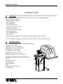
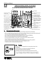
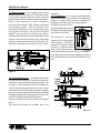
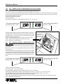
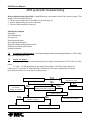
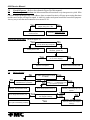
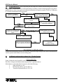
Match-Balance Series
4300SC Balancer
Service Manual
Form 5047-1
4300 Service Manual
TABLE OF CONTENTS
Page
4
5
6
7
8
9
10
11
12
13
14
15
16
Section
1.0
2.0
3.0
3.1
3.2
3.3
3.4
3.5
3.6
4.0
5.0
5.1
5.2
5.3
5.4
5.5
5.6
5.7
5.8
5.10
xxx
5.11
5.12
5.13
5.14
5.15
5.16
5.17
5.18
5.19
5.20
5.21
5.22
6.0
6.2
6.3
6.4
7.0
7.1
7.2
7.3
7.4
7.5
7.6
8.0
8.1
8.3
Subject
Introduction
Specifications
Systems explanations
Microcontroller PCB function
Encoder function
Brake system
Shaft and bearings
Transducers
Touch panel
Spin cycle explanation
Self diagnostics (F-code explanations)
F0 Recalculate and display weight amount from last spin
F1 Calibrate balancer for span factor and encoder offset
F2 Round off mode
F3 Non-round off mode
F4 Ounces mode
F5 Grams mode
F7 Convert wheel diameter to millimeters
F8 Weight placement angle size selection mode
F12 Calibrate distance gauge
F15/16 Programable threshold for gram mode
F20 Display shaft imbalance
F21 Shaft imbalance diagnostics
F30 Test the display
F31 Test the keyboard
F40 Display power supply voltage
F42 Display left amplifier gain and offset
F43 Display right amplifier gain and offset
F50 Display encoder position
F51 Display total encoder count
F53 Display shaft speed
F54 Calibrate encoder
F60 Display program revision level
F90 Match Balance
Other self diagnostic codes
Direction error
Cal error
Systematic troubleshooting
Check AC power
Check DC power
Check computer and touch panel functions
Spin cycle test
Weight position test
Weight amount test
Symptom Troubleshooting
Weight chasing
Dynamic Weight Chasing
2
4300 Service Manual
TABLE OF CONTENTS
Page
17
18
19
20
21
22
23
Section
8.3
8.4
8.5
9.0
10.0
10.1
10.2
10.3
10.4
10.5
10.6
10.7
Subject
Measure runout of bell housing
Transducer output diagnostics
Tire vibration after balance
Tools required for 4300 service
Disassembly and assembly of the 4300
Weight tray removal
Encoder removal
Transducer removal
Removing the shaft and bearings
Motor - Drive Assembly
Suspension system repair
Wheel Guard Assembly
3
4300 Service Manual
INTRODUCTION
1.0
Introduction The 4300 was introduced to fill a world wide market need. Many shops having space
restrictions will find the 4300 Balancer space efficient, extremely accurate and portable.
The 4300 Balancer features:
- Microcontroller Technology
- Ease of Operation
- Self Calibration
- Nine Balancing Modes
- Operation in Grams or Ounces
- Large wheel capacity
- 117/230 VAC power operation
- Built in diagnostics
- Low cost maintenance
- Ease of repair
- Multiple balancing applications with many optional mounting adapters available.
The 4300 Balancer is designed to handle today’s and tomorrow’s wheel balancing needs.
2.0
SPECIFICATIONS:
Types of Balance: Static, Dynamic, and Match Balancing
Accuracy: 0.1 oz. (2.8g)
Rim Width: 3"-19" (76-483mm)
Rim Diameter: 8"-24" (203-610mm)
Tire Diameter: 40" (1112mm)
Tire Weight: 154 lbs. (70kg)
Shipping Weight 305 lbs. (134kg)
Shipping Volume 38.8 cu.ft. (1.1 cu.M.)
This Manual Explains the following features:
Key Pad
Microcontroller PCB
Encoder System
Shaft and Bearings
Brake
Troubleshooting Procedures
Tools Required
4
4300 Service Manual
3.0
4300 SYSTEM(S) EXPLANATIONS
MICROCONTROLLER PRINTED CIRCUIT BOARD
LED Display
8 bit Latch for capturing
of address data
PROM: Holds all program
information
8x8 SRAM used to store
current spin information
Decoder for Encoder
input
7 Segment LED Driver used
to drive all LED displays
+5volt regulator (Digital)
Fuse .5amp 250VAC
Microcontroller: Controls all
Weight amount and weight
position calculations and the
addressing of calibration
factors.
+5volt regulator (analog)
-5volt regulator(analog)
Right Offset Adjustment
Audio Transducer: Used to
indicate completion of
function
Left Offset adjustment
Right Gain Control
Left Gain Control
EEPROM Used for storing
calibration factors
First stage filter amp
for transducer signal.
1 to 4 signal amp for
transducer signal.
10 to 4 Encoder Used for
keyboard input
Fgure 1
J2 Keyboard Connector
3.1
Microcontroller PCB Functions
- Receives Analog Data from Crystal pickups, determining weight amount calculations.
- Receives Digital data from Encoder System for determining weight position and shaft rotation speed.
Processes Analog and Digital Data through summing circuits.
- Stores input data in Ram and challenges calibration factors stored in EEPROM.
- Receives keyboard input and accesses ROM for program routine.
- Provides output through the LED readout, color position LEDs and piezo speaker.
- Provides diagnostic codes and readings stored in ROM.
- Allows manual calibration of the gain and offset adjustments for the pickup amplifier.
- Regulates voltage and provides fused protection for all digital circuits.
- Controls the motor rotation and braking functions.
3.2
Encoder
- Phase 1 and 2 are responsible for locating the position of the
imbalance.
- Home reference is used to sense shaft movement and
provide this input to the Microcontroller.
- Stabilizer arm is used to ensure the encoder does not rotate.
- Uses 100 windows which is multiplied 4 times by the computer
to give a reading of 400 (0 to 399) or a resolution of .9 degrees.
Figure 2
5
4300 Service Manual
3.3 Brake system: Used to stop the tire's rotation
during any part of it's spin cycle. The Brake system
is an electric-magnetic induction system using the
motor a bridge rectifier and some control electronics.
When a stop command or a brake command is
entered by the computer, a DC voltage is generated
by the bridge rectifier. This DC current is then
limited by a braking resistor, routed through a relay
and applied to the motor. An AC motor when fed
with DC current will tend to "Buck" any rotation.
This bucking will stop the rotation of the shaft. Shaft
rotation is sensed by the encoder circuit, as the shaft
stops the computer disconnects the DC brake. This
DC brake is also used for the "Sticky-at-Top" feature.
Bearings
assembly.
3.5 Transducers: Are used to provide imbalance
information to the Microcontroller. The input information is a voltage which varies in amplitude depending on the amount of force being applied.
The Microcontroller will begin calculating weight amount
readings once the proper transducer input is provided.
The transducers sense the
amount of force being applied
while spinning. This information of a repetitive static
imbalance coupled with the Transducer location
shaft speed information beFigure 5
ing provided by the encoder will provide the necessary information needed by the computer to calculate
the weight imbalance as well as the imbalance position.
Shaft
PCB
Figure 4
3.4 Shaft and Bearings: Are designed to operate
in a noise free environment. The shaft is balanced to
within 0.03 ounces at the time of manufacturing. The
bearings are Ball bearings which are shielded not
sealed. Sealed bearings induce noise in the system
and would not allow the bearings to operate smoothly.
A grease coating is applied to the bearings, shaft and
bearing housing to help eliminate noises which could
interfere with the operation of the balancer.
Locktite should not be used to hold the bearings in
place.
The shaft and bearings are available only as an
Transducer
input
Shaft
Figure 6
6
4300 Service Manual
3.6 Touch panel: Used for the entry of all commands to the microcontroller. It consists of a metal
plate for the mounting of the printed circuit board and
a vinyl overlay with an eleven conductor ribbon
cable. Twisting or crimping the ribbon cable will
damage the conductors. Striking the touch panel
with anything other than a finger may damage it.
Clean the touch panel with a dampened cloth of mild
ammonia or use a lanolin based hand cleaner without
grit. Don't use harsh chemicals to clean the touch
panel.
Figure 7
4.0
Spin cycle explanation
4300 Balancer
Spin cycle explanation
140 RPM
Encoder senses stable
speed
Motor Accelerates
wheel to
proper
RPM
Encoder & transducer
input becomes stable.
Computer looks for
equal transducer output during 2 rotations.
Position and weight
readings are taken for
10 rotations. LOC 1-8
is displayed.
Brake circuit is applied. Shaft
stops.
0 RPM
0 RPM
Weight amount displayed indicates end
of spin cycle
Time
7
4300 Service Manual
4300 Self diagnostic "F" Codes
5.0
The 4300 incorporates self diagnostics to assist the user and technician in troubleshooting, calibration and repair. Refer to the following for explanations of each available code.
5.1
F0 - RE-CALCULATE AND DISPLAY WEIGHT AMOUNT FROM LAST SPIN.
Data from the last spin in current memory is used with any new parameters or set-ups to
display new weight amounts. Current memory is maintained until the next spin cycle or until the unit
is turned off.
5.2
F1 - BALANCER CALIBRATION
(BASIC END-USER CALIBRATION)
Press “F1 and ENTER”
A: If EEPROM has not been initialized (this is the first time the board has been calibrated),
then the balancer will first ask for calibration of the distance gauge as follows:
1
2
3
4
5
6
Place
distance
gauge here
“CAL DIS” will be displayed.
Press “ENTER”.
Initialization calibration distance value (140) will be displayed.
Measure to left face of the bell flange with the distance gauge.
Enter this number via the keyboard.
Perform steps B.1 through B.7.
B: If EEPROM had already been initialized, then the balancer will go
directly to this procedure to set calibration factor for span and encoder
(end user calibration):
Figure 8
1 “CAL SLU” and "ROT 360" will be displayed alternately.
2 Install calibration slug onto left face of bell adapter. Rotate the bell at
least one full revolution
3 Press "ENTER", Place the calibration slug at the 6 o’clock or bottom
dead center (BDC) position. Press “ENTER”. “SPN SPN” will be
displayed as the shaft spins.
4 Unit will display “CAL —-” during readings, brake, and then display
“SLU OFF”.
5 Remove calibration slug.
6 Press enter. "SPN SPN” is displayed during spin cycle.
7 Unit will brake, then display “CAL G”.
Unit is now calibrated.
5.3
Cal Slug at
"BDC" Figure 9
F2 - ROUND-OFF MODE (WEIGHT AMOUNT DISPLAY)
Weight amounts are rounded off to the nearest 0.25 ounce (5 gram) increment. Imbalances of 0.30 ounces or less (8.5 grams
or less) will round to zero. This is the turn-on (or default) mode.
5.4
F3 - NON-ROUND-OFF MODE (WEIGHT AMOUNT DISPLAY)
Weight amounts are displayed in 0.05 ounce (1 gram) increments. This setting is in volatile memory, and reverts to “F2”
when the unit is turned on.
8
4300 Service Manual
5.5
F4 - OUNCES MODE
Sets weight amount display to ounces. This setting is in non-volatile memory. When the balancer is turned off and on, this mode
of operation will be maintained.
5.6
F5 - GRAMS MODE
Sets weight amount display to grams. This setting is in non-volatile memory. When the balancer is turned off and on, this mode
of operation will be maintained.
5.7
F7 - CONVERT WHEEL DIAMETER TO MILLIMETERS MODE
Allows direct entry of metric wheel diameters (i.e. 390 mm) when balancing this type of wheel. Selecting F7 toggles between
“CON ON” (dia in mm) and “CON OFF” (dia in inches).
Press any key to exit this set-up.
This setting is in volatile memory. When the balancer is turned off and back on, the setting reverts to “CON OFF” (dia in inches).
5.8
F8 - WEIGHT PLACEMENT ANGLE SIZE SELECTION MODE
The entry of this code causes the green light to be displayed for either one encoder count or two Selecting “F8” toggles between
the following modes:
1 .When the “FIN ON” message is displayed, the balancer will then be in the fine angle resolution mode (narrow
window).
The resolution for the wheel weight position display is set at 0.90 degrees (one encoder count).
2. When the “FIN OFF” message is displayed, the balancer will then be in the wide angle resolution mode
(wide window). The resolution for the wheel weight position display is set at 1.80 degrees (two encoder counts).
This display mode entry will be recorded in non-volatile memory. When the balancer is turned off and on, this mode of operation
will be maintained. The recommended mode is the FIN OFF for the majority of users.
5.10
“CAL DIS” will be displayed.
Press “ENTER” and the old factor will be displayed. Place the distance
gauge against the left face of the Shaft Adapter (bell). Read the distance
gauge, and enter the new reading into the computer through the
keyboard. The computer will automatically exit this routine when the
last digit has been entered.
This data entry will be recorded in non-volatile memory.
Even though the balancer is turned off and on, this information will be
maintained.
5.11
READ NEW
VALUES HERE
F12 - CALIBRATE DISTANCE GAUGE
í
ç PLACE GAUGE TIP
HERE
F20 - DISPLAY SHAFT IMBALANCE
The entry of this code causes the computer to display the shaft imbalance value which was recorded in non-volatile memory during
the last shaft imbalance diagnostic procedure (F21). For this information to be meaningful, the following parameters must be
entered: (DIST=62, WIDTH=5.5, DIA=13.0)
This information will remain the same until the F21 diagnostic procedure is run again.
5.13
F30 - TEST THE DISPLAY
The entry of this code causes the computer to turn on all 7 segments of each display block for 2 seconds.
Allows you to verify that all 7 segments of each LED is functioning. (All 7 segment displays show 8’s).
All characters will begin to scroll across the display in sequence.
This test also verifies the computer understands input commands and has the ability to provide correct output.
Press “CANCEL” to exit this routine.
5.14
F31 - TEST THE KEYBOARD
The entry of this code causes the computer to display each key as it is pressed.
With “CANCEL” being the last entry to be made, you can now press each key and verify the proper response is present on the
display.
Press “CANCEL” to exit this routine.
9
4300 Service Manual
5.16
F42 - DISPLAY LEFT AMPLIFIER GAIN AND OFFSET
This display is used to check and calibrate the left channel amplifier gain and off set.
Note: These values are only meaningful when using the standard calibration slug.
Locate the left gain and offset adjustment potentiometers through the access plugs or on the microcontroller PCB. See figure
below for POT location pictorial. The POT locations are labeled on the back side of the printed circuit board. Adjust using a
potentiometer adjustment screwdriver.
Calibrate gain and offset as follows;
Observing readings.
The left display should show a gain reading centered on 1.58 +/- 0.02 (volts)
Gain reading, adjust left gain
pot (R7) for 1.58 +/- 0.02
Offset reading adjust pot (R23)
for 2.50 +/- 0.01
Adjust left gain potentiometer until the proper readings are obtained .
RIGHT OFFSET
The right display should show the value of the amplifier offset voltage
LEFT OFFSET
centered on 2.50+/- 0.01 (volts) Adjust left offset potentiometer until
RIGHT GAIN
the proper readings are obtained .
LEFT GAIN
NOTE - The gain adjustment will have some effect on the offset
voltage. Make sure both displays are within specification.
Access-hole plugs
Press “CANCEL” to exit this routine.
5.17 F43- DISPLAY RIGHT AMPLIFIER GAIN
AND OFFSET
This display is used to check and calibrate the right channel amplifier
gain and offset
Note: These values are only meaningful when using the standard
calibration slug.
Locate the right gain and offset adjustment potentiometers through the
access plugs or on the microcontroller PCB. See figure below for POT
location pictorial. The POT locations are labeled on the back side of the
printed circuit board. Adjust using a potentiometer adjustment screwdriver.
Gain reading, adjust right gain
pot (R12) for 1.64 +/- 0.02
Offset reading, adjust pot (R17)
for 2.50 +/- 0.01
Calibrate gain and offset as follows;
Press enter to spin. Observing readings.
The right display should show a gain reading centered on 1.64 +/- 0.02 (volts)
Adjust right gain potentiometer until the proper readings are obtained . See figure 1, page 5 for pot location.
The right display should show the value of the amplifier offset voltage centered on 2.50+/- 0.01 (volts)
Adjust right offset potentiometer until the proper readings are obtained .
NOTE - The gain adjustment will have some effect on the offset voltage. Make sure both displays are within specification.
Press “CANCEL” to exit this routine.
10
4300 Service Manual
5.18
F40 - DISPLAY POWER SUPPLY VOLTAGE
Enter F40 and press enter, the display will read BRD VLT, meaning board voltage. The regulator voltage delivered by the power
source to the pcb (in volts) will be shown on the display.
The reading should be approximately 6.5 to 15.0 volts. Refer to the troubleshooting section of this manual for more details. This
test is valid for whatever the AC line input voltage options.
Press “CANCEL” to exit this routine.
5.19
F50 - DISPLAY ENCODER POSITION
Numbers between “0” and “399” will be displayed on the right display, indicating the current encoder pulse.
Dashes will be displayed on the left display, indicating phase “1” (first dash), phase “2” (second dash), and home reference (third
dash) of the encoder.
Press “CANCEL” to exit this routine.
5.20
F51 - DISPLAY TOTAL ENCODER COUNTS IN ONE REVOLUTION
Display should read “399” when the wheel is turning.
Press “CANCEL” to exit this routine.
5.21
F53 - DISPLAY SHAFT SPEED IN RPM
Spin the shaft and the RPM will be displayed, a reading of 140 +/- 10% is normal. Press “CANCEL” to exit this routine.
5.22
F54 - CALIBRATE ENCODER
Calibrates the encoder’s zero count..
Rotate the bell adapter one complete revolution and then press “ENTER”.
”ENC OFF” will be displayed.
Press ”ENTER” the encoder position will be displayed.
Install the calibration slug, and rotate the shaft so the slug is directly at the 6 o’clock position.
Press “ENTER” to cause the computer to record the present position as the correct encoder zero position stored in non-volatile
memory and exit the routine, or press “CANCEL” to exit this routine without changing the encoder calibration. F50 should be
checked after the running the F54 calibration to verify correct position.
5.23
F60 - DISPLAY PROGRAM REVISION LEVEL
Left hand display will show “43”, and right hand display will show revision level (i.e. “2.24”).
Press “CANCEL” to exit this routine.
6.0
OTHER SELF DIAGNOSTIC CODES
6.4
CAL ER : Will flash should a error occur during the calibration procedure or should the system detect a problem
when accessing the EEPROM for its calibration factors.
6.2
SHT UNB: Will flash after a calibration attempt whenever the shaft is unacceptably unbalanced. First review the
calibration procedure to assure that the correct steps are being followed. It is common for this message to appear because of a
calibration sequence has not been adhered to.
6.3
RPG/LPG LO: This is a message that appears whenever the pcb amplifier gains are set too low or whenever there
is some type of malfunction with one of the pickups. RPG stands for "Right Pickup Gain"; LPG stands for "Left Pickup Gain".
11
4300 Service Manual
4300 systematic troubleshooting
Basic troubleshooting of the 4300: is simplified using a systematic check of the various systems. This
manual will assume the following;
1. The neccesary hand tools are available (See tool list page 19)
2. A basic understanding of systems functions.
3. The use of this manual in its entirety.
Identify the symptom
No display
No keyboard entry
No spin cycle
No position indication
No weight amount display
Requires multiple spins to balance wheel
Vibration on vehicle after balance
No brake functions
7.0
Systematic troubleshooting: is a recommended procedure for repairing the balancer. Follow these
steps when repairing the 4300.
7.1
Check AC power:
AC power is used to power the transformer/power supply which converts 120/220 volts AC to DC
power
6.5 volts - 15 volts depending on the output of the adapter. DO NOT assume the power
outlet is good. Verify the AC output from the wall outlet by volt meter, substitution of a known
good AC powered device, or the use of a polarity tester.
Yes
Is there an LED display?
Press F-40. Is the reading
between 6.5-15.0?
No
Inspect switch and
connections.
Repair as required.
No
Is 6.5- 15 volts of DC power
present at Conector J1 pins 6&7?
Yes
Yes
DC power is OK.
Replace fuse F-1.
Yes
Is 6.5- 15 volts of DC power
present at plug J1.
Repair wires between J6 and J1.
No
Replace Microcontroller PCB if
LED display isn't present.
Replace power supply assembly.
12
4300 Service Manual
7.2
Check DC power: (Refer to the schematic Figure 20 of this manual).
7.3
Check computer functions: the Microcontroller self tests itself every time power is cycled. If the
CPU has found a problem in any of its address, data, or control circuits it will cease proccessing functions
and the sonic beeper will begin to sound. A stuck key on the touch panel would also cause this symptom.
An easy way to test the microcontroller is to run test F-30.
Yes
Are all characters being displayed during test F-30?
Microcontroller processing
circuits are OK.
No
Procede to testing the touch
panel
Testing the touch panel (Refer to figure 21)
Yes
Can you enter the command F-31
and do all the keys respond?
No
Jumper pins 4 & 11 of the J2
connector (power off).
Touch panel is OK.
Yes
(power on) Is there a display of
"6.13" on the display?
Replace Microcontroller PCB.
Replace Touchpanel.
7.4
Spin cycle test:
No
No
No
Will " SPN" display when
ENTER button is pressed?
Replace microcontroller PCB.
Go to weight amount test (7.5).
Spin cycle is functioning correctly.
Is "SPN" display when the shaft
is rotated?
Yes
No
Yes
With tire mounted will balancer
display "--- ---" while being spun
up to speed by hand?
Go to weight postion test (7.5).
when the wheel
Yes Is "SPN"hasdisplayed
stopped rotating?
Yes
Yes
Does the balancer display"--- ---"
constantly while being spun up to
speed?
Yes
No
No
Are weight amounts displayed
when the wheel has stopped
rotating?
13
4300 Service Manual
7.5
Weight position test: Before beginning the following tests; mount a calibration slug on the back
side of the shaft adapter. Turn the balancer on and spin the shaft using the "location 7" balancing mode.
No
Are all the position LEDs Lit?
No
Replace Microcontroller PCB.
No
No
Yes
Yes
Yes
Is the left green LED on with the
calibration slug at 6 o'clock.
Yes
Perform F-54 encoder calibration.
Perform F-50. Is the display reading
"000 ---" with the cal-slug at 6
o'clock?
Perform F-51. Does the display
read a number other than "399"
when the shaft is rotated 1 full
turn?
Yes
Yes
Weight position is OK.
Repair the encoder mounting or set
screw. If these are not loose
replace the encoder.
Measure for 4 to 5 volts at J1 pin
5. Is it there?
Measure J1 pins 2,3,4 with
O'scope set at 5volts/div and
20ms/div. While rotating the shaft
look for a +5 volt DC square wave.
Is it there?
Replace microcontroller PCB.
Yes
No
Replace Microcontroller PCB.
No
Measure J5 pins 1,3,4 using
O'scope as descibed in last step.
Are signals present?
Repair wiring harness between
encoder and J1 connector.
+6.6-15 VDC
No
Replace encoder.
J3
3 To: 110381
pcb
1
4.5 volts
Figure 10
14
4300 Service Manual
7.6
Weight amount test: Before beginning the following tests; mount a calibration slug on the balancer
adapter plate. Turn the balancer on. Insure the balancer is in the Location 1 balancing mode except where
indicated by flow chart. Any repairs or mechanical calibrations will require complete "End User" calibration
(F-1) before returning the 4300 to operation.
Perform F-1 calibration.
Does the 4300 calibrate?
Yes
Install Cal slug
No
Spin the balancer. Does it read
read 5.50 Ozs. (155g) in the left
window? (location 7)(F2mode)
Yes
Torque the transducers to 30 inch
pounds.
Yes
No
Looking at the left window during
F-42 or F-43. Does the gain
increase when the balancer is
spun?
Perform F-42 and F-43 calibraton.
(Refer to "F" codes for calibration)
Will it calibrate?
Yes
No
Remove calibration slug
Press "F3 enter"
Weight amount is working correctly.
Refer to symptom charts for other
weight amount problems.
When the balancer is spun, is the
left window display more than 0.10
during F-42,43?
Yes
Replace left or right transducer as
applicable. Calibrate and retest.
Weight amount is working correctly.
Refer to Symptom troubleshooting
for other weight amount problems.
8.0
No
No
Refer to Symptom troubleshooting
procedures
(8.1Weight Chasing).
Symptom troubleshooting
Symptom troubleshooting assumes all systematic troubleshooting techniques have been used and that the
various systems in the balancer are in working order.
8.1
Additional weight needed to balance tire. (Weight Chasing)
Static weight chase.
Using a balanced wheel assembly, enter the tire's parameters.
Place the cal slug on the balancer and using location 7, spin the balancer.
If the balancer reads other than 5.50 ounces, check the following;
1.
Shaft imbalance (F-20)
2.
Bell housing runout. (see 8.2 and 8.3)
3.
Transducer gain and offset (F-42, F-43)
15
4300 Service Manual
Dynamic weight chase
Remove the calibration slug.
Using "location 1"add a 3 ounce test weight to the inside plane of the wheel.
Spin the balancer. If the balancer reads other than 3 ounces check the following;
1. Bell housing runout.
2. Transducer gain and offset.
3. Mounting adapters
4. Transducer linearity. (the ability of the transducer to produce consistent output)
5. Distance gauge calibration or physical damage to the distance gauge.
If a reading of 3 ounces is obtained , move the weight to the outside plane. If the weight reads other than
3 ounces check the following;
1. Bell housing runout.
2. Transducer gain and offset.
3. Mounting adapters
4. Transducer linearity. (the ability of the transducer to produce consistent output)
5. Distance gauge calibration or physical damage to gauge.
Figure 12
Runout should be measured when the balancer requires more than one weight per tire
side to balance the wheel.
Bell housing runout not to exceed
0.002 of an inch.
8.3
Measuring Bell face runout
16
4300 Service Manual
8.4
Transducer Output: Using
Location mode 7 and F-42 for the left
transducer and right transducer, check
the transducer linear output in the following manner;
Use a balanced wheel
5oz
4oz.
3oz.
1) Spin the balancer until the green
LED position indicator is lit.
Output should be 0.00 to 0.10 with a
balanced wheel.
2) Add a one ounce weight to the inside
plane. Refer to the chart and then to the
reading.
2oz.
1oz.
0 oz.
X+
010
020 030 040 050
Gain displayed in left window
Determine transducer linear output
3) Continue to add weight using only
1 weight in the same wheel position.
Readings should be very close +/- 0.10
to those values shown on the chart.
5oz
4) Remove the right and left transducer
connections from the main PCB.
Connect the right transducer plug to the
left transducer connector on the Main
PCB.
Perform the steps 1 to 3.
Again the readings should compare to
the chart. Numeric values may be vary
but linear output should remain constant.
4oz.
3oz.
2oz.
1oz.
0 oz.
X+ 010 020 030 040 050
Gain displayed in left window right transducer.
If the transducer will not give a linear
output replace it. Torque the new transducer in place and re-test.
5oz
5) Be sure to calibrate (F-1) the balancer when you have completed this
procedure.
3oz.
4oz.
2oz.
Use the blank chart to record your actual 1oz.
readings for the left and right transduc0 oz.
ers.
X+ 010 020 030 040 050
Gain displayed in left window for left transducer.
17
4300 Service Manual
8.5
Tire vibration after the balance: Generally speaking this condition will occur in a wheel
throughout all speed ranges if the balancer is not working properly.
If the condition only exists during given speed range look for:
Tire runout (radial and axial),
Bent rims
Wheels which are not hub centric. (Rims that are not centered by the center hole) and require the use
of an optional mounting method.
Damaged bearing races or bent axles.
If the balancer has passed all systematic troubleshooting procedures and it appears to be functioning
correctly, check the following:
1. Follow the procedures given for the F-20 and F-21 (shaft imbalance test)
2. Check cones for play when mounted to the shaft.
Cone tolerance is .003 inches of up and down movement on the shaft.
3. Check the encoder's Phase 1 and Phase 2 signal to ensure they are at 90 degrees to each other.
(See figure 2 and troubleshooting guide for weight position)
4. Check the torque of the suspension system bolts.
If these suggestions do not solve your problem.
Remember
FMC is striving to be OUR CUSTOMERS MOST VALUED EQUIPMENT SUPPLIER.
If you require additional assistance;
Phone our technical assistance desk at:
1-800 FMC-TEAM inside the continental United States or
1 - (501) 327-4433 for all overseas customers.
Our FAX number is (501)-450-1585
Please direct all technical questions to the attention of technical assistance.
18
4300 Service Manual
9.0
Tools required to service the 4300
Tools Required to service the 4300
Wrenches
Other Tools
5/16" or 8mm wrench or nut driver
1/2" or 13mm Wrench
9/16" or 14mm wrench
5/8" wrench
3/4" or 17mm wrench
Inch pound torque wrench
Foot pound torque wrench
6 inch in1/16" increments or 50mm ruler
#2 Phillips or cross tip screwdriver
Digital volt / ohm meter
Potentiometer adjustment screwdriver
Allen Wrenches
1/8" Allen wrench
5/32" Allen wrench
3/16" Allen wrench
5/16" or 8mm Allen wrench
12mm Allen wrench
Supplies
Loctite #222 and #609
Silicone based grease (NAPA Balkamp #765-1351)
Putty for fine wheel balancing.
**A tire/wheel balanced to within 0.10 oz (1gr.) on the inside and outside or 0.20 oz.
statically is required for the troubleshooting procedures.
19
4300 Service Manual
10.0
Disassembly of the 4300
(1) Remove 4 screws
(2) Remove 4 screws
(3) Remove cover
(*) wiring connections to PCB.
10.1 Remove the weight tray
and Microcontroller PCB
Remove the top cover of the 4300 by
removing the Touchpanel first. Be careful when pulling the panel back and
watch for the wires which are attached
to the PCB.(*)
Disconnect the wires by gently raising
the connector clip and pulling back on
the wire's socket. DO NOT PULL ON
THE WIRES OR ATTEMPT PULLING UP ON THE CONNECTOR.
Squeeze the touchpanel's connector side
clips and gently pull back to disconnect
the flat ribbon cable.
Refer to the drawing and remove the
upper cover in the numbered order.
Assembly is the reverse order.
Figure 13
10.2 Removing the Encoder
Refer to the drawing and remove the encoder in the numbered
order. Assembly is the reverse of disassembly. Care should be
taken to insure the encoder's slotted shaft is correctly inserted in
the shaft opening. The encoder should not wobble when the shaft
is turned.
Once installation of the encoder is complete and power is restored
to the balancer, you will need to refer to the Encoder calibration
section of this manual to complete the installation procedure.
Follow the numbered sequence in the drawing for removal of the
transducers. The transducers have two small balls held in
10.3
(4) Lift out
(3)
(2)
(1)
Figure 14
Transducer removal
position by the torque of the set screw. Grease is applied to these
balls during assembly to help hold them in place.
When placing the transducer back in the machine be sure the cables
are disconnected to avoid damage to the transducer and apply more
grease. Torque the transducer to 30 inch lbs., loosen 1/2 turn then
torque again to 30 inch pounds. Once power has been restored to
the machine refer to the F42 and F43 calibraton procedure in this
(2) Loosen
(1) Loosen nut
manual to set ampifier gain and offset. F1 calibration must be
set screw
Figure 15 performed after making any transducer adjustments. Remember if
you were to adjust the bearing support or the shaft housing this
would effect transducer torque and you would need to adjust as necessary.
(3) Remove as one
20
4300 Service Manual
10.4
Removing the Shaft and Bearings
Refer to the numbered sequence below for removal of the shaft and bearings from the 4300. !!During the
removal of the shaft care
(2) Loosen set screw
should be taken to not
damage the bearings
through heavy impact.
(3) Remove
The shaft and bearings are
encoder
available only as an assembly. Inspect for burrs
(4) Remove pulor rust in the bearing tube
ley nut
before returning the shaft
(6) Remove 3 screws
to service. Coat the bear(5) Remove Pulley
ings and the bearing seat
with silicone grease to protect the bearings from rust
(7)Remove shaft
and eliminate noise.
After complete assembly
of all shaft components,
(1) Remove bell adapter
refer to the shaft calibration portion of this manual.
Figure 16
Use the F-1 calibration procedure to complete the installation of the shaft and bearing assembly.
10.5 Motor Drive
Service of the 4300 Balancer Motor-Drive
assembly is quite crucial. Proper belt tension should always be maintained. Normal
operation as well as rough shipping prior to
installation may require this tension be adjusted. Inspection of the shaft bearing tube
where mounted to the motor/shaft bracket
should reveal no slippage. If found to have
slipped, use this procedure to adjust:
The specifications for drive belt adjustment are as follows:
1. The belt should be set with tension
that allow a 3/8" deflection of the belt
halfway between the pulleys with 10 to 12
pounds of force. Belt tension should be
neither too loose or too tight.
Figure 17
21
4300 Service Manual
2. If a start-up torque is unusually high, a loose belt may allow the motor to jump several teeth. Because excessive tension also creates problems, there must be a medium acceptable range. It has been
determined that the easiest way to field adjust is to mount a heavy wheel/tire assembly that would allow
belt slippage if belt were loose. Gradually increase motor tension until belt no longer skips teeth.
3. Tighten mounting bolts to the following specs:
Motor bracket mounting bolts, (4) 3/8-16x1 is 20 foot pounds.
Motor mount nuts, (4) 10-24, is 32 inch pounds.
NOTE:
Inspection of the shaft bearing tube where mounted to the motor/shaft bracket should
reveal no downward slippage. Rough shipping or handling could cause the motor and bracket assembly
to slip downward. Any downward movement of the motor will tighten the belt tension. If found to have
slipped, use the above procedure to adjust.
10.6 Suspension system: The bearing tube,
shaft and bearings are designed to work in a low noise
and free floating environment.
Limited service is required for this system.
After removal of the shaft/bearing assembly, remove
the four bearing tube suspension bolts. (see figure
19) Remove the tube.
Assembly of the suspension is the reverse of disassembly. Deviation of the assembly procedure will
add to your assembly time.
Center the tube front and rear as shown in figure 18
Torque the top rear suspension nut to 60 inch pounds.
When the proper torque has been obtained, check the
bearing tube for proper centering. Adjust as necessary.
Figure 18
Center tube in housing 1 5/16"
(33mm) alternating top and bottom bolts
Torque the front suspension bolts to 35 foot pounds
alternating from top to bottom one quarter turn at a time.
Once assembly of the balancer has been completed perform all calibration steps to the unit. Please refer to
the calibration section of this manual.
22
4300 Service Manual
Torque to 60 inch pounds
(2)
(4)
Torque to 35 foot pounds
and tighten lock nuts.
(6)
(5)
(1) Remove shaft and
bearings
(3)
Figure 19
Assemble in reverse order (6,5,4,3,2,1)
10.6 Wheel Guard Assembly Installation or removal of the hood guard for service
or initial setup requires only a small hammer to tap in a roll pin. For installation simply insert
the guard support pivot pin into the balancer support tube. Make sure the pivot pin is all the
way into tube, place the roll pin into the drilled hole of the pivot. Tap into place.
NOTE: The balancer must be secured to the floor prior
to installation of the hood guard.
ñ
ñ
ñ
ñ
Roll Pin
23
4300 Service Manual
Reference drawings, charts and figures
page
Section
5
5
6
6
6
7
8
8
14
16
20
20
20
21
21
22
23
23
27
3.0
3.2
3.4
3.5
3.5
3.6
5.2
5.2
7.5
8.3
10.1
10.2
10.3
10.4
10.5
10.6
10.6
10.7
Drawing,chart, or figure.
Figure 1 Microcontroller PCB
Figure 2 Encoder
Figure 4 Shaft and bearings layout
Figure 5 Transducer location
Figure 6 Transducer location and wiring connections
Figure 7 Touch panel layout
Figure 8 Distance gauge calibration location
Figure 9 Calibration slug at Bottom Dead Center
Figure 10 Wiring diagram
Figure 12 Measure bell housing runout
Figure 13 Disassembly of the weight tray
Figure 14 Disassembly of the encoder
Figure 15 Disassembly of the transducers
Figure 16 Disassembly of the shaft and bearings
Figure 17 Disassembly of the motor drive assembly
Figure 18 Bearing Tube centering
Figure 19 Disassembly of the bearing tube.
Figure 20 Hood guard
Figure 21 Touch Panel layout
24
4300 Service Manual
4300 Wiring Diagrams
25
4300 Service Manual
4300 Wiring
Diagram -230 Volt
Model
26
4300 Service Manual
4300 Touch panel layout
A Jumper wire placed on the J2
connector between any two button
connections enters the button's command and display.
J2 connector as seen from the rear
of the microcontroller PCB.
Jumper wire between 4 & 11 produces the distance gauge display.
The default display will be "6.13"
Figure 21
Hood Wiring Diagram
27
4300 Service Manual
4300 Encoder Wiring Harness
Power
Control PCB
Main PCB
Encoder
28
Match-Balance
Series
Automotive Service Equipment Division
Exchange Avenue
Conway Arkansas 72032 USA
Form 5047-1..FMC4300serv.pm5 cullum
Printed in U.S.A