1
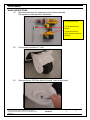
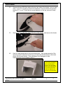
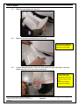
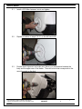
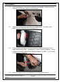
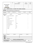
Rev
1
Description
SERVICE MANUAL
Date
ECO#
2/14/08
00239
Document Number:
040-00077
Form Instructions
Title
Operation
Description
Standards
Equipment
List
SERVICE MANUAL, FRONT FENDER REPLACEMENT
Sub Assembly
Man Occup.
Machine Occup.
Equipment
Cycle Time
Setup Time
Manufacturer
Batch Qty
Qty
1- Front fender
T3 Motion
1
2- 5/16 inch drill
Any
1
3- 5/32 inch Allen driver
Any
1
Document #
Description
Description
Document #
Reference
Docs
Related
Files
RESP
ENGR
Mark Jones
ALL TEXT AND GRAPHICS
COMPUTER GENERATED, DO
NOT REVISE MANUALLY
T3MOTION, INC. PROPRIETARY INFORMATION
This document is the sole property of T3MOTION, Inc. The release of data
contained in this document and the reproduction of this document in whole
or in part, without the written permission of T3MOTION, Inc. is prohibited.
SHEET 1 of 8
Form 040-00077 Rev.1
SERVICE MANUAL
Item#
Part #
Description
Qty
1
500-00099
Front Fender
1
T3MOTION PROPRIETARY INFORMATION
Use or disclosure of data contained on this sheet is
subject to the restriction on the cover or title page of this
document.
Document No
Revision
040-00077
1
Sheet
2
SERVICE MANUAL
Serious electrical
shock can occur
if precautions are
not followed.
• ALWAYS TURN OFF POWER BREAKER IN GLOVE BOX AND REMOVE POWER
MODULES BEFORE PERFORMING ANY ELECTRICAL WORK.
Power breaker in glove box
Power modules
• ALSO SET THE PARKING BRAKE PRIOR TO ANY WORK.
Parking brake
T3MOTION PROPRIETARY INFORMATION
Use or disclosure of data contained on this sheet is
subject to the restriction on the cover or title page of this
document.
Document No
Revision
040-00077
1
Sheet
3
SERVICE MANUAL
WORK INSTRUCTIONS:
1.0
Recommended tools for replacing the front fender assembly.
See equipment table above for the details.
2- 5/16 drill bit in drill
3- 5/32 Allen driver on
ratchet
3- 5/32 Allen wrench
(Only one Allen wrench is
required)
2.0
Front fender mounted on T3 unit.
3.0
Remove the two 5/32 Allen bolts at the axle, (one on each side).
T3MOTION PROPRIETARY INFORMATION
Use or disclosure of data contained on this sheet is
subject to the restriction on the cover or title page of this
document.
Document No
Revision
040-00077
1
Sheet
4
SERVICE MANUAL
3.2
Remove the two 5/32 Allen bolts at the top rear sides of the fender, (one on each
side). If your T3 unit has only these four fasteners, remove fender and proceed
to step 4.0. If your T3 unit has two more fasteners on the top, proceed to step
3.3.
3.3
Remove the two 5/32 Allen bolts at the top of the fender, and remove the fender.
4.0
Here is a new fender with out any mounting holes. Take measurements of the
mounting holes locations from the one you removed and drill holes in the same
places into the new fender. If the old fender is too damaged to take
measurements from proceed to step 4.1.
Note:
You will only be drilling
four mounting holes.
Even if your old fender
had six mounting points,
mount the new fender
with four fasteners as
shown in the next steps.
T3MOTION PROPRIETARY INFORMATION
Use or disclosure of data contained on this sheet is
subject to the restriction on the cover or title page of this
document.
Document No
Revision
040-00077
1
Sheet
5
SERVICE MANUAL
4.1
Slide the new fender onto the fork.
4.2
Make sure it sits level with the top of the fork.
Also check for clearance
of the fender and body in
this area on both sides.
5.0
Locate where the center of the front axle meets the right hand side of the front
fender and drill a 5/16 inch hole at that point.
Note that the visual
center of the fender
depression may not be
the actual center of the
axle.
Check from different
angles before drilling.
T3MOTION PROPRIETARY INFORMATION
Use or disclosure of data contained on this sheet is
subject to the restriction on the cover or title page of this
document.
Document No
Revision
040-00077
1
Sheet
6
SERVICE MANUAL
5.1
Install a 5/32 Allen fastener, but do not tighten.
5.2
Repeat procedure in steps 5.0-5.1 on the left hand side.
5.3
Double check alignment and make sure there is no interference between the
body and the upper rear of the fender. Then drill a hole that corresponds to the
mounting point on the fork.
T3MOTION PROPRIETARY INFORMATION
Use or disclosure of data contained on this sheet is
subject to the restriction on the cover or title page of this
document.
Document No
Revision
040-00077
1
Sheet
7
SERVICE MANUAL
5.4
Install the fastener for the upper left side, but do not tighten. Repeat procedure
in step 4.6 for the upper right side mounting point.
5.5
Tighten all four fasteners in the order you installed them. The inside of the
fender should be flush with the mounting points.
6.0
Check to make sure there is sufficient clearance between the left rear of the
fender and the drive pulley. It should have ¼ inch or more of clearance. If more
clearance is needed, gently pull and bend the bracket out a little. ¼ to ½ inches
of clearance is in tolerance.
7.0
Check for range of motion and clearance before test driving vehicle.
T3MOTION PROPRIETARY INFORMATION
Use or disclosure of data contained on this sheet is
subject to the restriction on the cover or title page of this
document.
Document No
Revision
040-00077
1
Sheet
8