1
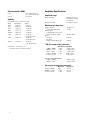
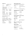
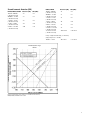
Agilent
PSA Series Spectrum Analyzers
Data Sheet
E4443A
E4445A
E4440A
E4446A
E4448A
3 Hz to 6.7 GHz
3 Hz to 13.2 GHz
3 Hz to 26.5 GHz
3 Hz to 44 GHz
3 Hz to 50 GHz
The Agilent PSA Series offers high-performance spectrum analysis, up to 50 GHz, with
powerful one-button measurements, a versatile feature set, and a leading-edge combination of flexibility, speed, accuracy, and dynamic range. From millimeter wave and phase
noise measurements to spur searches and
modulation analysis, the PSA Series offers
unique and comprehensive high-performance
solutions to R&D and manufacturing engineers
in cellular and emerging wireless communications, aerospace, and defense.
Table of contents
Definitions and Conditions . . . . . . . . . . . . . . . . . . . . . . . . . . .3
Specifications for the PSA Series Spectrum Analyzers . . . .4
Frequency Specifications . . . . . . . . . . . . . . . . . . . . . . . . . .4
Frequency range . . . . . . . . . . . . . . . . . . . . . . . . . . . . .4
Frequency reference . . . . . . . . . . . . . . . . . . . . . . . . . .4
Frequency readout accuracy . . . . . . . . . . . . . . . . . . . .4
Marker frequency counter . . . . . . . . . . . . . . . . . . . . .4
Frequency span . . . . . . . . . . . . . . . . . . . . . . . . . . . . . .4
Sweep time and triggering . . . . . . . . . . . . . . . . . . . . .4
Sweep (trace) point range . . . . . . . . . . . . . . . . . . . . .4
Gated FFT . . . . . . . . . . . . . . . . . . . . . . . . . . . . . . . . . . .4
Resolution bandwidth (RBW) . . . . . . . . . . . . . . . . . . .4
Information bandwidths . . . . . . . . . . . . . . . . . . . . . . .4
Video bandwidth (VBW) . . . . . . . . . . . . . . . . . . . . . . .6
Stability . . . . . . . . . . . . . . . . . . . . . . . . . . . . . . . . . . . . .6
Amplitude Specifications . . . . . . . . . . . . . . . . . . . . . . . . . .6
Amplitude range . . . . . . . . . . . . . . . . . . . . . . . . . . . . .6
Maximum safe input level . . . . . . . . . . . . . . . . . . . . . .6
1dB gain compression (two tone) . . . . . . . . . . . . . . .6
Typical gain compression (two tone) . . . . . . . . . . . . .6
Displayed average noise level (DANL) . . . . . . . . . . . .7
Display range . . . . . . . . . . . . . . . . . . . . . . . . . . . . . . . .8
Frequency response . . . . . . . . . . . . . . . . . . . . . . . . . .8
Input attenuation switching uncertainty . . . . . . . . . .8
Absolute amplitude accuracy . . . . . . . . . . . . . . . . . . .8
Input voltage standing wave ratio (VSWR) . . . . . . . .8
Resolution bandwidth switching uncertainty . . . . . .8
Reference level . . . . . . . . . . . . . . . . . . . . . . . . . . . . . .8
Display scale switching uncertainty . . . . . . . . . . . . .8
Display scale fidelity . . . . . . . . . . . . . . . . . . . . . . . . . .8
Spurious response . . . . . . . . . . . . . . . . . . . . . . . . . . . .8
Second harmonic distortion (SHI) . . . . . . . . . . . . . . .9
Third-order intermodulation distortion (TOI) . . . . . . .10
Residual responses . . . . . . . . . . . . . . . . . . . . . . . . . . .11
Trace detectors . . . . . . . . . . . . . . . . . . . . . . . . . . . . . .11
Option E444xA-1DS, preamplifier . . . . . . . . . . . . . . . .11
Measurement speed . . . . . . . . . . . . . . . . . . . . . . . . . .11
2
Power Suite Measurement Specifications . . . . . . . . . . . .12
Channel power . . . . . . . . . . . . . . . . . . . . . . . . . . . . . . .12
Occupied bandwidth . . . . . . . . . . . . . . . . . . . . . . . . . .12
Adjacent channel power . . . . . . . . . . . . . . . . . . . . . . .12
Multi-carrier power and ACP . . . . . . . . . . . . . . . . . . .12
Power statistics CCDF . . . . . . . . . . . . . . . . . . . . . . . . .12
Harmonic distortion . . . . . . . . . . . . . . . . . . . . . . . . . . .12
Intermod (TOI) . . . . . . . . . . . . . . . . . . . . . . . . . . . . . . .12
Burst power . . . . . . . . . . . . . . . . . . . . . . . . . . . . . . . . .12
Spurious emission . . . . . . . . . . . . . . . . . . . . . . . . . . . .12
Spectrum emission mask (SEM) . . . . . . . . . . . . . . . .12
General Specifications . . . . . . . . . . . . . . . . . . . . . . . . . . . .12
Temperature range . . . . . . . . . . . . . . . . . . . . . . . . . . . .12
EMI compatibility . . . . . . . . . . . . . . . . . . . . . . . . . . . . .12
Audio noise . . . . . . . . . . . . . . . . . . . . . . . . . . . . . . . . .12
Military specification . . . . . . . . . . . . . . . . . . . . . . . . . .12
Power requirements . . . . . . . . . . . . . . . . . . . . . . . . . .12
Weight . . . . . . . . . . . . . . . . . . . . . . . . . . . . . . . . . . . . .13
Dimensions . . . . . . . . . . . . . . . . . . . . . . . . . . . . . . . . .13
Warranty . . . . . . . . . . . . . . . . . . . . . . . . . . . . . . . . . . . .13
Calibration cycle . . . . . . . . . . . . . . . . . . . . . . . . . . . . .13
Input and Outputs . . . . . . . . . . . . . . . . . . . . . . . . . . . . . . . .13
Front panel . . . . . . . . . . . . . . . . . . . . . . . . . . . . . . . . . .13
Rear panel . . . . . . . . . . . . . . . . . . . . . . . . . . . . . . . . . .13
Ordering Information . . . . . . . . . . . . . . . . . . . . . . . . . . . . . . . .14
PSA Series spectrum analyzer . . . . . . . . . . . . . . . . . . . . .14
Options . . . . . . . . . . . . . . . . . . . . . . . . . . . . . . . . . . . . . . . .14
Product Literature . . . . . . . . . . . . . . . . . . . . . . . . . . . . . . . . . .15
Warranty and Contact Information . . . . . . . . . . . . . . . . . . . . .16
Definitions and Conditions
Specifications describe the performance of parameters
covered by the product warranty and apply over 0 to 55 °C
unless otherwise noted. Typical describes additional product
performance information that is not covered by the product
warranty. It is performance beyond specifications that 80 percent of the units exhibit with a 95 percent confidence level
over the temperature range 20 to 30 °C. Typical performance
does not include measurement uncertainty.
Nominal values indicate expected performance, or describe
product performance that is useful in the application of the
product, but is not covered by the product warranty.
The analyzer will meet its specifications when:
• stored a minimum of two hours within the operating
temperature range and turned on for at least 30 minutes
with Auto Align On selected.
• the instrument is within its one year calibration cycle.
• Align All Now has been performed within the past 24
hours or when the temperature changes 3 °C.
• the instrument is under auto couple control, except that
Auto Sweep Time = Accy.
• DC coupling applied if center frequency is < 20 MHz.
This PSA Series data sheet is a summary of the complete
specifications and conditions, which are available in the PSA
Series Spectrum Analyzers Specification Guide.
The PSA Series Spectrum Analyzers Specification Guide can
be obtained on the web through:
www.agilent.com/find/psa
Then follow this selection process:
• Select “Manuals, Guides & Services Notes” from “In the
Library”.
• Select “PSA Series Spectrum Analyzers Specifications
Guide”.
• Download specifications guide.
3
Frequency Specifications
Frequency range
E4443A
E4445A
E4440A
E4446A
E4448A
Band
(DC coupled)
(AC coupled)
(DC coupled)
(AC coupled)
(DC coupled)
(AC coupled)
(DC coupled)
(DC coupled)
3 Hz to 6.7 GHz
10 MHz to 6.7 GHz
3 Hz to 13.2 GHz
10 MHz to 13.2 GHz
3 Hz to 26.5 GHz
10 MHz to 26.5 GHz
3 Hz to 44 GHz
3 Hz to 50 GHz
Harmonic
mixing mode (N)
0
1
2
3
4
5
6
1–
1–
2–
4–
4–
4+
8–
3 Hz to 3 GHz
2.85 GHz to 6.6 GHz
6.2 GHz to 13.2 GHz
12.8 GHz to 19.2 GHz
18.7 GHz to 26.8 GHz
26.4 GHz to 31.15 GHz
31.0 GHz to 50.0 GHz
Frequency reference
Accuracy
Aging rate
Temperature stability
20 °C to 30 °C
0 °C to 55 °C
Calibration accuracy
± [(time since last adjustment x aging rate)
+ temperature stability + calibration accuracy]
± 1 x 10⁻⁷ / year
Sweep time and triggering
Range:
Span = 0 Hz
Span ≥ 10 Hz
Accuracy
Span ≥ 10 Hz, sweep
Span ≥ 10 Hz, FFT
Span = 0 Hz
Trigger
Trigger delay
Span = 0 Hz, or FFT
Span ≥ 10 Hz, swept
Resolution
Example frequency reference accuracy 1 year after last adjustment:
= ±(1 x 1 x 10–7 + 1 x 10⁻⁸ + 7 x 10⁻⁸)
= ±1.8 x 10⁻⁷
Frequency readout accuracy (start, stop, center, marker)
± (marker frequency x frequency reference accuracy + 0.25 percent
x span + 5 percent x RBW + 2 Hz + 0.5 x horizontal resolution*)
*Horizontal resolution is span/(sweep points – 1)
±0.01% nominal
±40% nominal
±0.01% nominal
Free run, line, video, RF burst,
external front, external rear
–150 ms to +500 ms
1 µs to 500 ms
0.1 µs
Sweep (trace) point range
Span = 0 Hz
Span ≥ 10 Hz
2 to 8192
101 to 8192
Gated FFT
Maximum span
Delay range
Delay resolution
Gate duration
10 MHz
–150 to +500 ms
100 ns or 4 digits whichever is more
1.83/RBW ±2% nominal
Resolution bandwidth (RBW)
Range (–3.01 dB bandwidth)
± 1 x 10⁻⁸
± 5 x 10⁻⁸
± 7 x 10⁻⁸
1 µs to 6000 s
1 ms to 2000 s
1 Hz to 3 MHz (10% steps), 4,
5, 6, 8 MHz
Bandwidth accuracy (power):
RBW range
1 Hz to 51 kHz
56 kHz to 75 kHz
82 kHz to 330 kHz
360 kHz to 1.2 MHz (< 3 GHz CF)
1.3 MHz to 2.0 MHz (< 3 GHz CF)
2.2 MHz to 6.0 MHz (< 3 GHz CF)
±0.5% (±0.022 dB)
±1.0% (±0.044 dB)
±0.5% (±0.022 dB)
±1.0% (±0.044 dB)
±0.07 dB nominal
±0.02 dB nominal
Bandwidth accuracy (–3.01 dB):
RBW range
8 MHz (< 3 GHz CF)
±15% nominal
Selectivity (–60 dB/–3 dB)
4.1:1 nominal
Marker frequency counter
Accuracy
± (marker frequency x frequency reference
accuracy + 0.100 Hz)
Delta counter accuracy ± (delta frequency x frequency reference
accuracy + 0.141 Hz)
Counter resolution
0.001 Hz
Frequency span (FFT and swept mode)
Range
Resolution
Accuracy
4
0 Hz (zero span), 10 Hz to maximum
frequency of model
2 Hz
± [0.2 percent x span + span / (sweep points – 1)]
Information bandwidths
Maximum FFT width
10 MHz
I/Q waveform digital output
bandwidth (Option E444xA-B7J)
10 MHz
321.4 MHz IF output:
–1 dB bandwidth
20 to 30 MHz nominal
–3 dB bandwidth
30 to 60 MHz nominal
70 MHz IF output (Option E444xA-H70):
–1 dB bandwidth
20 to 30 MHz nominal
–3 dB bandwidth
30 to 60 MHz nominal
Nominal phase noise at common cellular
communication frequencies, £(f) optimized versus f
Figure 1. Nominal phase noise at common cellular frequencies
Nominal phase noise of different center frequencies with
RBW selectivity curves, £(f) optimized versus f
Figure 2. Nominal phase noise at various center frequencies
5
Video bandwidth (VBW)
Range
Accuracy
1 Hz to 3 MHz (10% steps),
4, 5, 6, 8 MHz and wide open
± 6% nominal
Amplitude Specifications
Amplitude range
Measurement range
Displayed average noise
level (DANL) to maximum
safe input level
0 to 70 dB in 2 dB steps
Stability
Noise sidebands (20 °C to 30 °C, CF = 1 GHz)
Offset
Specification
Typical
100 Hz
–91 dBc/Hz
–97 dBc/Hz
1 kHz
–103 dBc/Hz
–107 dBc/Hz
10 kHz
–114 dBc/Hz
–117 dBc/Hz
30 kHz
–114 dBc/Hz
–117 dBc/Hz
100 kHz
–120 dBc/Hz
–123 dBc/Hz
1 MHz
–144 dBc/Hz
–146 dBc/Hz
–148 dBc/Hz nominal
6 MHz
–151 dBc/Hz
–152 dBc/Hz
–156 dBc/Hz nominal
10 MHz
–151 dBc/Hz
–152 dBc/Hz
–157.5 dBc/Hz nominal
Residual FM: < (1 Hz X N) p-p in 1 s
See frequency range for N (harmonic number)
Input attenuator range
Maximum safe input level
Average total power
Preamp (Option E444xA-1DS)
Peak pulse power
< 10 µs pulse width, < 1% duty cycle
and input attenuation ≥ 30 dB
DC volts:
DC coupled
AC coupled
(E4443A, E4445A, E4440A only)
+30 dBm (1 W)
+25 dBm
+50 dBm (100 W)
< ±0.2 Vdc
±100 Vdc
1 dB gain compression (two-tone)
20 MHz to 200 MHz
200 MHz to 3 GHz
3 GHz to 6.6 GHz
6.6 GHz to 26.5 GHz
26.5 GHz to 50 GHz
Total power at input mixer
0 dBm
+3 dBm nominal
+3 dBm
+7 dBm nominal
+3 dBm
+4 dBm nominal
–2 dBm
0 dBm nominal
0 dBm nominal
Preamp on (Option E444xA-1DS)
10 MHz to 200 MHz
200 MHz to 3 GHz
–30 dBm nominal
–25 dBm nominal
Typical gain compression (two-tone)
20 MHz to 200 MHz
200 MHz to 6.6 GHz
6.6 GHz to 26.5 GHz
6
Mixer level
0 dBm
+3 dBm
–2 dBm
Compression
< 0.5 dB
< 0.5 dB
< 0.4 dB
Displayed Average Noise Level (DANL)
(Input terminated, sample or average detector, averaging type = Log, 20 to 30 °C)
Zero span and swept
normalized to 1 Hz RBW
and 0 dB attenuation
Zero span and swept
normalized to 1 Hz RBW
and 0 dB attenuation
(typical)
FFT only
actual 1 Hz RBW
0 dB attenuation
–110 dBm nominal
–130 dBm nominal
–142 dBm
–149 dBm
–153 dBm
–156 dBm
–155 dBm
–154 dBm
–153 dBm
–152 dBm
–149 dBm
–145 dBm
—
—
–135 dBm
–145 dBm
–150 dBm
–154 dBm
–153 dBm
–152 dBm
–151 dBm
–149 dBm
–146 dBm
–143 dBm
–164 dBm
–167 dBm
–168 dBm
–170 dBm
–169 dBm
–167 dBm
–160 dBm
–163 dBm
–165 dBm
–168 dBm
–167 dBm
–165 dBm
–110 dBm nominal
–130 dBm nominal
–143 dBm
–150 dBm
–155 dBm
–155 dBm
–154 dBm
–153 dBm
–152 dBm
–149 dBm
–147 dBm
–146 dBm
–144 dBm
–145 dBm
–136 dBm
–132 dBm
–134 dBm
–131 dBm
–130 dBm
—
—
–140 dBm
–145 dBm
–150 dBm
–153 dBm
–152 dBm
–151 dBm
–150 dBm
–146 dBm
–144 dBm
–143 dBm
–140 dBm
–141 dBm
–133 dBm
–129 dBm
–131 dBm
–127 dBm
–126 dBm
–164 dBm
–167 dBm
–168 dBm
–169 dBm
–169 dBm
–168 dBm
–166 dBm
–159 dBm
–162 dBm
–163 dBm
–166 dBm
–167 dBm
–166 dBm
–164 dBm
E4443A/E4445A/E4440A
3 Hz to 1 kHz
—
1 kHz to 10 kHz
—
10 kHz to 100 kHz
–135 dBm
100 kHz to 1 MHz
–145 dBm
1 MHz to 10 MHz
–150 dBm
10 MHz to 1.2 GHz
–155 dBm
1.2 GHz to 2.5 GHz
–154 dBm
2.5 GHz to 3.0 GHz
–153 dBm
3 GHz to 6.6 GHz
–152 dBm
6.6 GHz to 13.2 GHz
–150 dBm
13.2 GHz to 20 GHz
–147 dBm
20 GHz to 26.5 GHz
–143 dBm
Preamp ON (Option E4443/5/0A-1DS)
100 kHz to 200 kHz
–161 dBm
200 kHz to 500 kHz
–164 dBm
500 kHz to 10 MHz
–166 dBm
10 MHz to 1.1 GHz
–169 dBm
1.1 GHz to 2.5 GHz
–168 dBm
2.5 GHz to 3.0 GHz
–166 dBm
E4446A/E4448A
3 Hz to 1 kHz
—
1 kHz to 10 kHz
—
10 kHz to 100 kHz
–140 dBm
100 kHz to 1 MHz
–145 dBm
1 MHz to 10 MHz
–150 dBm
10 MHz to 1.2 GHz
–154 dBm
1.2 GHz to 2.2 GHz
–153 dBm
2.2 GHz to 3 GHz
–152 dBm
3 GHz to 6.6 GHz
–151 dBm
6.6 GHz to 13.2 GHz
–146 dBm
13.2 GHz to 20 GHz
–145 dBm
20 GHz to 22.5 GHz
–143 dBm
22.5 GHz to 26.8 GHz
–140 dBm
26.8 GHz to 31.15 GHz
–142 dBm
31.15 GHz to 36 GHz
–134 dBm
36 GHz to 38 GHz
–129 dBm
38 GHz to 44 GHz
–131 dBm
44 GHz to 49 GHz
–128 dBm
49 GHz to 50 GHz
–127 dBm
Preamp ON (Option E4446/8A-1DS)
100 kHz to 200 kHz
–160 dBm
200 kHz to 500 kHz
–163 dBm
500 kHz to 10 MHz
–164 dBm
1 MHz to 10 MHz
–167 dBm
10 MHz to 1.2 GHz
–167 dBm
1.2 GHz to 2.2 GHz
–166 dBm
2.2 GHz to 3.0 GHz
–164 dBm
7
Display range
Log scale
Linear scale
Scale units
Absolute amplitude accuracy
0.1 to 1 dB/division in 0.1 dB steps
1 to 20 dB/division in 1 dB steps
(10 display divisions)
10 divisions
dBm, dBmV, dBuV, V, and W
Frequency response
(10 dB input attenuation, 20 to 30 °C, preselector centering applied)
E4443A/E4445A/E4440A
3 Hz to 3 GHz
±0.38 dB
3 GHz to 6.6 GHz
±1.50 dB
6.6 GHz to 22 GHz
±2.00 dB
22 GHz to 26.5 GHz
±2.50 dB
E4446A/E4448A
3 Hz to 3 GHz
3 GHz to 6.6 GHz
6.6 GHz to 22 GHz
22 GHz to 26.8 GHz
26.4 GHz to 31.15 GHz
31.15 GHz to 50 GHz
±0.38 dB
±1.50 dB
±2.00 dB
±2.50 dB
±1.75 dB
±2.50 dB
(10 dB attenuation, 20 to 30 °C, 10 Hz ≤ RBW ≤ 1 MHz, input signal
–10 to –50 dBm, all settings auto-coupled except Auto Swp Time = Accy,
any reference level, any scale)
At 50 MHz
±0.24 dB (±0.06 dB typical)
At all frequencies
± (0.24 dB + frequency response)
± (0.06 dB+ frequency response) typical
3 Hz to 3 GHz
(95% confidence)
±0.24 dB
Preamp on (Option E444xA-1DS)
(±0.11 dB typical)
(±0.6 dB typical)
(±1.0 dB typical)
(±1.3 dB typical)
(±0.15 dB typical)
(±0.6 dB typical)
(±1.2 dB typical)
(±1.3 dB typical)
(±0.6 dB typical)
(±1.0 dB typical)
Frequency response at attenuation ≠ 10 dB
(Atten = 20, 30, or 40 dB)
10 MHz to 2.2 GHz
±0.53 dB
2.2 GHz to 3 GHz
±0.69 dB
Input voltage standing wave ratio (VSWR)
(≥ 8 dB input attenuation)
50 MHz to 3 GHz
3 GHz to 18 GHz
18 GHz to 26.5 GHz
26.5 GHz to 50 GHz
< 1.2:1 nominal
< 1.6:1 nominal
< 1.9:1 nominal
< 1.6:1 nominal
Preamp on (50 MHz to 3 GHz)
(≥ 10 dB attenuation)
< 1.2:1 nominal
Resolution bandwidth switching uncertainty
(referenced to 30 kHz RBW)
1 Hz to 1 MHz RBW
1.1 MHz to 3 MHz RBW
4, 5, 6, 8 MHz RBW
Preamp on (Option E444xA-1DS), (for all models)
100 kHz to 3 GHz
±0.70 dB
< (±0.30 dB typical)
Reference level
Input attenuation switching uncertainty
Range:
Log scale
Linear scale
Accuracy
(Attenuator setting ≥ 2 dB)
At 50 MHz
3 Hz to 3 GHz
3 GHz to 13.2 GHz
13.2 GHz to 26.5 GHz
26.5 GHz to 50 GHz
±0.18 dB
±0.3 dB nominal
±0.5 dB nominal
±0.7 dB nominal
±1.0 dB nominal
± (0.36 dB + frequency response)
± (0.09 dB+ frequency response) typical
±0.03 dB
±0.05 dB
±1.0 dB
-170 dBm to +30 dBm in 0.01 dB steps
707 pV to 7.07 V in 0.1% steps
0 dB
Display scale switching uncertainty
Switching between
linear and log
Log scale/div switching
0 dB
0 dB
Display scale fidelity
≤ –20 dBm input mixer level
±0.07 dB total
–20 dBm < mixer level ≤ –10 dBm ±0.13 dB total
Spurious response (mixer level = –40 dBm)
General spurious:
f < 10 MHz from carrier
f ≥ 10 MHz from carier
See frequency range for N
8
(–73 + 20 log N) dBc
(–80 + 20 log N) dBc
(–90 + 20 log N) dBc typical
Second harmonic distortion (SHI)
E4443A, E4445A, E4440A
10 MHz to 400 MHz
(–40 dBm mixer level)
400 MHz to 1.25 GHz
(–40 dBm mixer level)
1.25 GHz to 1.5 GHz
(–40 dBm mixer level)
1.5 GHz to 2.0 GHz
(–10 dBm mixer level)
2.0 GHz to 13.25 GHz
(–10 dBm mixer level)
Distortion (dBc)
–82
SHI (dBm)
+42
–92
+52
–82
+42
–90
+80
–100
+90
E4446A, E4448A
10 MHz to 400 MHz
(–40 dBm mixer level)
400 MHz to 1.25 GHz
(–40 dBm mixer level)
1.25 GHz to 1.5 GHz
(–40 dBm mixer level)
1.5 GHz to 2.0 GHz
(–10 dBm mixer level)
2.0 GHz to 3.25 GHz
(–10 dBm mixer level)
3.25 GHz to 13.25 GHz
(–10 dBm mixer level)
13.25 GHz to 25 GHz
(–10 dBm mixer level)
Distortion (dBc)
–82
SHI (dBm)
+42
–91
+51
–81
+41
–90
+80
–94
+84
–96
+86
–100 nominal
+90 nominal
Preamp on (Option E444xA-1DS), (for all models)
(input preamp level = –45 dBm)
10 MHz to 1.5 GHz
–60 nominal
+15 nominal
Nominal dynamic range
Band 0
Figure 3. Nominal dynamic range - Band 0, for second and third order distortion,
E4443A, E4445A, and E4440A - 3 Hz to 3 GHz
9
Nominal dynamic range
Bands 1 to 4
Figure 4. Nominal dynamic range – Bands 1 to 4, second and third order distortion,
E4443A, E4445A, E4440A - 3 GHz to 26.5 GHz
Third-order intermodulation distortion (TOI)
(two –30 dBm tones at input mixer with tone separation
> 15 kHz, 20 to 30 °C )
E4443A/E4445A/E4440A
10 MHz to 100 MHz
100 MHz to 400 MHz
400 MHz to 1.7 GHz
1.7 GHz to 3.0 GHz
3.0 GHz to 6.0 GHz
6.0 GHz to 16 GHz
16 GHz to 26.5 GHz
10
Distortion (dBc)
–88
–90
–92
–94
–90
–76
–84
TOI (dBm)
+14 (+17 typical)
+15 (+18 typical)
+16 (+19 typical)
+17 (+19 typical)
+15 (+18 typical)
+8 (+11 typical)
+12 (+14 typical)
E4446A/E4448A
10 MHz to 100 MHz
100 MHz to 400 MHz
400 MHz to 1.7 GHz
1.7 GHz to 3.0 GHz
3.0 GHz to 6.0 GHz
6.0 GHz to 16 GHz
16.0 GHz to 26.5 GHz
26.5 GHz to 50 GHz
Distortion (dBc)
–90
–92
–94
–96
–92
–84
–84
–85 nominal
TOI (dBm)
+15 (+20 typical)
+16 (+21 typical)
+17 (+20 typical)
+18 (+21 typical)
+16 (+21 typical)
+12 (+15 typical)
+12 (+16 typical)
+12.5 nominal
Preamp on (Option E444xA-1DS), (for all models, two –45 dBm tones at
preamp input)
10 MHz to 500 MHz
–15 nominal
500 MHz to 3 GHz
–13 nominal
Residual responses
Option E444xA-1DS, preamplifier
Input terminated and 0 dB attenuation
200 kHz to 6.6 GHz
–100 dBm
6.6 GHz to 26.8 GHz
–100 dBm nominal
26.8 GHz to 50 GHz
–90 dBm nominal
Frequency range
Gain
Noise figure
100 kHz to 3 GHz
28 dB nominal
7 dB nominal
Measurement speed
Trace detectors
Normal, peak, sample, negative peak, log power average,
RMS average, and voltage average
Local measurement and display update rate
Remote measurement and GPIB transfer rate
101 sweep points
401 sweep points
601 sweep points
≥ 50/s nominal
≥ 45/s nominal
≥ 30/s nominal
≥ 25/s nominal
Nominal dynamic range
for second- and third-order distortion bands 5 and 6
26.5 GHz to 50 GHz
Figure 5. Nominal dynamic range – Bands 5 to 6, E4446A and E4448A - 26.4 GHz to 50 GHz
11
Power Suite Measurement Specifications
Spurious emission
Channel power
cdma2000 or W-CDMA (1980 MHz region, 1.2 MHz RBW)
Table driven spurious signals; search across regions.
Relative dynamic range
80.6 dB (82.4 dB typical)
Absolute sensitivity
–89.7 dBm (–91.7 dBm typical)
Amplitude accuracy, W-CDMA or IS95
(20 to 30 °C, mixer level < –20 dBm) ±0.68 dB ( ±0.18 dB typical)
Spectrum emission mask (SEM)
Occupied bandwidth
Frequency accuracy
± [span/600] nominal
Adjacent channel power
Accuracy, W-CDMA (ACLR) (at specific mixer levels and ACLR ranges):
Adjacent
Alternate
MS
±0.12 dB
±0.17 dB
BTS
±0.22 dB
±0.22 dB
Dynamic range (typical):
w/o noise correction
–74.5 dB
–82 dB
w/noise correction
–81 dB
–88 dB
Offset channel pairs measured
1 to 6
Multi-carrier power and ACP
ACPR dynamic range, W-CDMA (5 MHz offset, RRC weighted,
3.84 MHz noise bandwidth):
Two carriers
–70 dB nominal
Four carriers
–68 dB nominal
ACPR accuracy (two carriers,
5 MHz offset, –48 dBc ACPR)
±0.38 dB nominal
Multiple number of
carriers measured
Up to 12
cdma2000 (750 kHz offset):
Relative dynamic range
85.3 dB (88.3 dB typical)
(30 kHz RBW)
Absolute sensitivity
–105.7 dBm (–107 dBm typical)
Relative accuracy
±0.09 dB
3GPP W-CDMA (2.515 MHz offset):
Relative dynamic range
87.3 dB (89.5 dB typical)
(30 kHz RBW)
Absolute sensitivity
–105.7 dBm (–107.7 dBm typical)
Relative accuracy
±0.10 dB
General Specifications
Temperature range
Operating
Storage
0 °C to +55 °C
–40 °C to +75 °C
EMI compatibility
•
•
Conducted interference is in compliance with
CISPR Pub 11/1990 Group 1 Class A
Radiated emission is in compliance with
CISPR Pub 11/1990 Group 1 Class B
Power statistics CCDF
Histogram resolution
0.1 dB
ISO 7779
Harmonic distortion
Maximum harmonic number
Results
Intermod (TOI)
10th
Fundamental power (dBm), relative
harmonics power (dBc), total
harmonic distortion in percent
Measure the third-order products and intercepts from two tones
Burst power
Methods
Results
12
Audio noise
Power above threshold, power
within burst width
Single burst output power, average
output power, maximum power,
minimum power within burst,
burst width
LNPE < 5.0 BELS at 25 °C
Military specification
Type tested to environmental specifications MIL-PRF-28800F Class 4
Power requirements
Voltage and frequency:
100 to 132 Vrms, 47 to 66 Hz/360 to 440 Hz
195 to 250 Vrms, 47 to 66 Hz
Power consumption:
On
Standby
< 260 watts, no options
(< 450 watts, all options)
< 20 watts
Weight (without options)
Rear panel
E4443A, E4445A, E4440A
Net
Shipping
23 kg (50 lbs) nominal
33 kg (73 lbs) nominal
E4446A, E4448A
Net
Shipping
24 kg (53 lbs) nominal
34 kg (76 lbs) nominal
Dimensions
Height
Width
Length
177 mm (7.0 in)
426 mm (16.8 in)
483 mm (19 in)
Warranty
The E4440A, E4443A, E4445A, E4446A and E4448A are supplied
with a three-year warranty.
Calibration cycle
The recommended calibration cycle is one year. Calibration services
are available through Agilent service centers.
Input and Outputs
Front panel
RF input
Connector:
E4443A/E4445A
E4440A
Option E4440A-BAB
E4446A/E4448A
Probe power
Voltage/current (nominal)
Headphone
Ext trigger input
Connector
Impedance
Trigger level
Type-N female, 50 Ω
Type-N female, 50 Ω
APC 3.5 male
2.4 mm male, 50 Ω
+15 Vdc, ±7% at 150 mA max
–12.6 Vdc, ±10% at
150 mA max GND
Reserved for future applications
BNC female
10 kΩ nominal
5 V TTL nominal
10 MHz OUT (switched)
Connector
Output amplitude
Frequency accuracy
Ext Ref In
Connector
Input amplitude range
Input frequency
Frequency lock range
Trigger in
Connector
External trigger input:
Impedance
Trigger level
BNC female, 50 Ω
≥ 0 dBm nominal
10 MHz ± (10 MHz x frequency
reference accuracy)
BNC female, 50 Ω
–5 to +10 dBm nominal
1 to 30 MHz nominal
± 5 x 10⁻⁶ of specified external
reference input frequency
BNC female
> 10 kΩ nominal
5 V TTL nominal
Trigger 1 and Trigger 2 outputs
Connector
BNC female
Trigger 1 output:
HSWP (high = sweeping)
Impedance
50 Ω nominal
Level
5 V TTL
Trigger 2 output
Reserved for future applications
Monitor output
Connector
Format
Resolution
Noise source drive output
Connector
Output voltage
On
Off
Remote programming
GPIB interface:
Connector
GPIB codes
Serial interface connector
LAN TCP/IP interface
VGA compatible, 15-pin mini D-SUB
VGA (31.5 kHz horizontal, 60 Hz
vertical sync rates, non-interlaced)
Analog RGB
640 X 480
BNC female
28.0 ± 0.1 V (60 mA maximum)
<1V
IEEE-488 bus connector
SH1, AH1, T6, SR1, RL1, PP0, DC1,
C1, C2, C3, and C28, DT1, L4, C0
9-pin D-SUB male (factory use only)
RJ45 Ethertwist
Parallel printer interface connector
25-pin D-SUB female
321.4 MHz IF output
Connector
Frequency
Conversion gain
SMA female, 50 Ω nominal
321.4 MHz nominal
+2 to +4 dB nominal
13
Ordering Information
PSA Series spectrum analyzer
E4443A
E4445A
E4440A
E4446A
E4448A
3 Hz to 6.7 GHz
3 Hz to 13.2 GHz
3 Hz to 26.5 GHz
3 Hz to 44 GHz
3 Hz to 50 GHz
Options
To add options to a product, use the following ordering scheme:
Model
E444xA (x = 0, 3, 5, 6 or 8)
Example options E4440A-B7J
E4448A-1DS
Digital demodulation hardware
E444xA-B7J
Digital demodulation hardware (required for digital
demodulation measurement personalities)
Digital demodulation measurements
E444xA-BAF
E444xA-202
E444xA-B78
E444xA-204
E444xA-BAC
E444xA-BAE
W-CDMA measurement personality
GSM w/ EDGE measurement personality
cdma2000 measurement personality
1xEV-DO measurement personality
cdmaOne measurement personality
NADC, PCD measurement personality
General purpose measurements
E444xA-226
E444xA-219
Phase noise measurement personality
Noise figure measurement personality
Amplifiers
E444xA-1DS
100 kHz to 3 GHz built-in preamplifier
Inputs and outputs
E4440A-BAB
Replaces type "N" input connector with APC 3.5
connector
Connectivity software
E444xA-230
BenchLink Web Remote Control Software
Code compatibility
E444xA-266
1
14
HP 8566B/8568B code
compatibility measurement personality
Options not available in all countries.
Accessories
E444xA-1CM
E444xA-1CN
E444xA-1CP
E444xA-1CR
E444xA-045
E444xA-0B1
Rack mount kit
Front handle kit
Rack mount with handles
Rack slide kit
Millimeter wave accessory kit
Extra manual set including CD ROM
Warranty and service
For warranty and service of 5 years, please order 60 months of R-51B (
quantity = 60). Standard warranty is 36 months.
R-51B
Return-to-Agilent warranty and service plan
Calibration1
For 3 years, order 36 months of the appropriate calibration plan shown
below. For 5 years, specify 60 months.
R-50C-001
R-50C-002
Standard calibration
Standards compliant calibration
E444xA-OBW
E444xA-UK6
Service manual and calibration software
Commercial calibration certificate with test data
Product Literature
PSA Series, brochure, literature number 5980-1283E
PSA Series, data sheet, literature number 5980-1284E
Self-Guided Demonstration for Spectrum Analysis,
product note, literature number 5988-0735EN
For more information on the PSA Series, please visit:
www.agilent.com/find/psa
Phase Noise Measurement Personality, technical overview,
literature number 5988-3698EN
Noise Figure Measurement Personality, technical overview,
literature number 5988-7884EN
W-CDMA Measurement Personality, technical overview,
literature number 5988-2388EN
GSM with EDGE Measurement Personality,
technical overview, literature number 5988-2389EN
cdma2000 Measurement Personality,
technical overview, literature number 5988-3694EN
1xEV-DO Measurement Personality,
technical overview, literature number 5988-4828EN
cdmaOne Measurement Personality,
technical overview, literature number 5988-3695EN
NADC/PDC Measurement Personality,
technical overview, literature number 5988-3697EN
Optimizing Dynamic Range for Distortion Measurements,
product note, literature number 5980-3079EN
PSA Series Amplitude Accuracy,
product note, literature number 5980-3080EN
PSA Series Swept and FFT Analysis,
product note, literature number 5980-3081EN
PSA Series Measurement Innovations and Benefits,
product note, literature number 5980-3082EN
8 Hints for Millimeter Wave Spectrum Measurements,
application note, literature number 5988–5680EN
PSA Series Spectrum Analyzers, Option H70,
70 MHz IF Output, product overview,
literature number 5988-5261EN
PSA Series Spectrum Analyzer Performance Guide
Using 89601A Vector Signal Analysis Software,
product note, literature number 5988-5015EN
89600 Series + PSA, 802.11A and HiperLAN2 ODFM
Measurements, product note,
literature number 5988-4094EN
Selecting the Right Signal Analyzer for Your Needs,
selection guide, literature number 5968-3413E
HP 8566B/68B Programming Code Compatibility for
PSA and ESA-E Series Spectrum Analyzers, product
overview, literature number 5988-5808EN
BenchLink Web Remote Control Softeware,
product overview, literature number 5988-2610EN
IntuiLink Software, Data Sheet,
Literature Number 5980-3115EN
15
Agilent Technologies’ Test and Measurement Support, Services, and Assistance
Agilent Technologies aims to maximize the value you receive, while minimizing your
risk and problems. We strive to ensure that you get the test and measurement
capabilities you paid for and obtain the support you need. Our extensive support
resources and services can help you choose the right Agilent products for your
applications and apply them successfully. Every instrument and system we sell has
a global warranty. Support is available for at least five years beyond the production life
of the product. Two concepts underlie Agilent’s overall support policy: “Our Promise”
and “Your Advantage.”
Our Promise
Our Promise means your Agilent test and measurement equipment will meet its
advertised performance and functionality. When you are choosing new equipment, we
will help you with product information, including realistic performance specifications and practical recommendations from experienced test engineers. When
you use Agilent equipment, we can verify that it works properly, help with
product operation, and provide basic measurement assistance for the use of
specified capabilities, at no extra cost upon request. Many self-help tools are available.
Your Advantage
Your Advantage means that Agilent offers a wide range of additional expert test
and measurement services, which you can purchase according to your unique technical and business needs. Solve problems efficiently and gain a competitive edge
by contracting with us for calibration, extra-cost upgrades, out-of-warranty repairs,
and onsite education and training, as well as design, system integration, project
management, and other professional engineering services. Experienced Agilent
engineers and technicians worldwide can help you maximize your productivity, optimize the return on investment of your Agilent instruments and systems, and obtain
dependable measurement accuracy for the life of those products.
Agilent Email Updates
www.agilent.com/find/emailupdates
Get the latest information on the products and applications you select.
Agilent T&M Software and Connectivity
Agilent’s Test and Measurement software and connectivity products, solutions and
developer network allows you to take time out of connecting your instruments to
your computer with tools based on PC standards, so you can focus on your tasks,
not on your connections. Visit www.agilent.com/find/
connectivity for more information.
By internet, phone, or fax, get assistance with all your test & measurement needs
Phone or Fax
United States:
(tel) 800 452 4844
Canada:
(tel) 877 894 4414
(fax) 905 282 6495
China:
(tel) 800 810 0189
(fax) 800 820 2816
Europe:
(tel) (31 20) 547 2323
(fax) (31 20) 547 2390
Japan:
(tel) (81) 426 56 7832
(fax) (81) 426 56 7840
Korea:
(tel) (82 2) 2004 5004
(fax) (82 2) 2004 5115
Latin America:
(tel) (305) 269 7500
(fax) (305) 269 7599
Taiwan:
(tel) 0800 047 866
(fax) 0800 286 331
Other Asia Pacific Countries:
(tel) (65) 6375 8100
(fax) (65) 6836 0252
Email: [email protected]
Online Assistance:
www.agilent.com/find/assist
Product specifications and descriptions in this document subject to change
without notice.
© Agilent Technologies, Inc. 2002
Printed in USA, December 17, 2002
5980-1284E