1
DRAFT (For official use only) GOVERNMENT OF INDIA MINISTRY OF RAILWAYS SPECIFICATION FOR B.G. SELF PROPELLED OHE RECORDING CAR FOR ELECTRIC TRACTION SPECIFICATION No. TI/SPC/OHE/SPRC/0011 Issued by: T.I.DIRECTORATE RESEARCH DESIGNS & STANDARDS ORGANISATION MANAK NAGAR, LUCKNOW – 226 011 PRICE: 1of 93 Effective from……. TI/SPC/OHE/SPRC/…. SPECIFICATION FOR B.G. SELF PROPELLED OHE RECORDING CAR FOR ELECTRIC TRACTION SPECIFICATION NO. TI/SPC/OHE/SPRC/0011 Amendment Date of Total pages including Amendment/Revision Number Amendment annexure. 0 NA First issue. PREPARED BY CHECKED BY APPROVED BY SIGNATURE DATE DESIGNATION SE/CAR DTI-II EDTI COPY NUMBER ISSUED BY ……………. SIGNATURE DATE…………… ISSUED TO ……………………………………………………………… ……………………………………………………………… NOTE : This specification is property of RDSO. No reproduction shall be done without permission from DG (TI), RDSO. This specification is not for general use. 1 2of 93 Effective from……. TI/SPC/OHE/SPRC/…. This draft specification for self-propelled NETRA car for recording of OHE parameters has been prepared T I Directorate of RDSO Lucknow, Government of India, Ministry of Railways, Manak Nagar Lucknow 226 011,India and uploaded on RDSO web site. All interested manufacturer and supplier of car may give their suggestion/comments to improve the specification at the earliest. This car shall be employed on the Indian Railway to record OHE parameters of electric traction under live condition of OHE charged at 25 kV ac. User railways may also give their comments. All the comments may reach this office to Executive Director/TI by 15th April 2011. E mail ID is [email protected]. 2 3of 93 Effective from……. TI/SPC/OHE/SPRC/…. PART – I FOREWARD: On 25kV a.c. electrified routes, different types of overhead equipment (OHE) have been provided, ranging from fixed type un-regulated OHE without articulation to the present auto tensioned sagged regulated OHE. In and around Mumbai area, 1500 V d.c. traction system also exists, which is under conversion to 25 kV a.c. system. However, the dynamic behaviour of different types of OHEs with regard to current collection at different speeds has not been evaluated both qualitatively and quantitatively. Various parameters like height, stagger, wear of the contact wire, condition of OHE at the crossovers are at present measured/ checked manually and/or with the one available NETRA car, which is time consuming. Current collection performance is monitored by noticing the sparks at night and/or through OLIVER-G equipment. These methods suffer from errors in measurements and individual judgment. The single NETRA car available with IR is not adequate to scan the entire electrified network of IR which at present is 20059 RKM (as on 31.03.2010). Indian Railways have embarked on a large-scale program of the electrification. To cater for increase in traffic, heavier freight trains upto 9000t load are being introduced, which are to be hauled with consist of one or two electric locomotives. The speed of passenger trains is also being gradually increased to reach 160 km/h and beyond. The introduction of high speed trains as well as the increase in traffic will necessitate more frequent and accurate monitoring of OHE parameters. The Self Propelled OHE parameter recording cum-test car is required to measure and record various parameters of OHE and pantograph in static/ dynamic conditions and under live and non-live conditions of OHE, upto a maximum speed 130 km/h when coupled to a train and 105 kmph when running by its own power. GENERAL REQUIREMENTS 1. EXPLANATORY Throughout this specification the term – 1.1 RDSO: Research Designs and Standards Organization, Manak Nagar, Lucknow-226011 is hereafter referred to as RDSO. 1.2 IR: Indian Railways is hereafter referred to as IR. 1.3 Engineer: Director of RDSO is hereafter referred to as Engineer. 1.4 IRS: Indian Railway Standard is hereafter referred to as IRS 1.5 IS: Indian Standard is hereafter referred to as IS. 1.6 ICF: Integral coach factory, Chennai is hereafter referred to as ICF. 1.7 „Purchaser‟ means Railway Board on behalf of The President of Republic of India. 1.8 „Inspecting Officer‟ means the persons, firms or departments nominated by the Purchaser to inspect the work on his behalf and the deputies of the Inspecting Officer so nominated. 3 4of 93 Effective from……. TI/SPC/OHE/SPRC/…. 1.9 „Contractor‟ means the person, firm or company from whom the Purchaser may obtain any material or fittings to be used for the work. 1.10 `Contract Drawings‟ means the drawings, which are included in Annexure – I of this specification for the guidance of the contractor. The ICF drawings mentioned in this Annexure – I, should be collected from ICF, Chennai. 1.11 IEC 1.12 : International Electro-technical Commission 1.13 UIC: Union International Des Chemins defer (International Union of Railways) 1.14 Horse Power (HP) shall be taken as metric horse power i.e.75 kg metre/sec. 1.15 Tonnes (T) shall be taken as metric ton i.e.1000kg. 1.16 Overhead equipment is hereafter referred to as OHE 1.17 Self Propelled Overhead equipment parameter recording cum test car is hereafter referred as OHE Car 2. SCOPE OF THE SPECIFICATION 2.1 This specification covers the requirements of design, development, manufacturing and supply, testing, delivery and commissioning into service of suitable capacity of Self Propelled Overhead Equipment parameter recording cum test car with Stainless steel shell & Modern Interiors and high tech measuring equipments in completely assembled and furnished condition, hereafter referred as Car for operation on BG section of 1676 mm gauge of Indian Railways. 2.2 The scope shall also include the following: a) b) c) d) e) f) 2.3 Provision of all documentation and support material associated with the operation and maintenance of the cars Ongoing technical support and defects liability coverage until the completion of the warranty period and making good defects. Training of engineers, operations and maintenance staff including providing the training materials, training kits and demonstration equipment. Initial supply and installation of all consumables and materials required for testing and commissioning. Provision of final drawings, design calculations and other documents including operations and maintenance manuals for review and acceptance by the Purchaser‟s Representative. Manufacture of cars in India, progressively, within a defined time frame, and within a programmed manner. The cars should have the following features: a) b) c) Good aesthetics High comfort levels Passenger amenities 4 5of 93 d) e) f) g) h) i) j) k) l) m) n) o) 2.4 Effective from……. TI/SPC/OHE/SPRC/…. Ease of maintenance Longer periodicity between overhauls Low life cycle cost Low weight Flush level/ smooth exteriors. Use of interchangeable, modular components Extensive and prominent labeling of parts High reliability Fire and smoke detection Use of fire retardant materials Environment friendly Maximum possible commonality of structure, components, equipments and subsystems in the different types of cars. This specification consists of six parts as follows: Part I: Chapter –I Chapter-II Chapter-III Part II: Part III: Part IV: Part V: Part VI: Part vii: General requirement OHE Parameters to be measured Construction of OHE Car and working environment Operating and Service Condition Mechanical Requirement Power Equipment & Control Electrical Equipments & Power Supply Arrangement Test Schedule of quantities 2.5 The stock shall meet the operating requirements specified in Part II of this specification, and shall be suitable for conditions of loading mentioned therein. 2.6 The contractor shall, in addition to observing and complying with this specification, be bound by the standard terms and conditions of contract for the design construction, supply and delivery of OHE Car. 2.7 This specification is intended to include everything requisite to the construction of OHE Car, notwithstanding that everything required may not be mentioned herein, the supplier shall ensure that the OHE Car is complete in all respect and fit for operation. 2.8 The existing OHE recording cum test car is similar to a coaching stock of IR. Proposed OHE recording cum test car shall be self propelled and shall have driving cabs on either ends. The space for accommodating, two DG sets of 50 kVA with sound proof compartment, a well furnished air conditioned instrument room and other identical area like observation dome and staff/officer‟s cabin including adequate lights and fans shall be provided. Provision shall be made for keeping computers, UPS with batteries, other accessories necessary for recording and generating reports with adequate power supply points at convenient locations as per approved layout. Provision shall be made for observation dome with comfortable sitting arrangement to view interaction of contact wire and pantograph alongwith the fitment of load cell/accelerometers, transducers/ sensors/ instruments etc. as required for the purpose. Cupboards shall be provided for storage of catalogues and spare parts. All items/equipments required to make the OHE recording car fully operational to measure and record the proposed OHE parameters will fall under the scope of supply of the successful tenderer, whether specifically mentioned or not. This 5 6of 93 Effective from……. TI/SPC/OHE/SPRC/…. includes final testing of the entire system including the commissioning trials over Indian Railway Track to check the overall efficacy of the system with desired precision/accuracy. 2.9 The measuring equipment and associated electronic interface shall be fit for measuring OHE parameters with car running at speeds up to 105 kmph with its own power and up to 130 kmph when coupled to a train. 2.10 If there be any point of difference between the specification and/or exhibited drawings that this specification fails to clarify, the tenderer shall submit each such item to RDSO for immediate clarification. 2.11 Any additional item of work or equipment which may be considered necessary by the purchaser, after placement of order, and during the process of manufacture shall be carried out by the successful tenderer on the terms and conditions mutually agreed to between the purchaser and successful tenderer. 2.12 The interior, where the computers and instrumentation system and living accommodation etc. are provided, shall be air conditioned with maximum relative humidity of 40-60% and average dry bulb temperature of 20-250C. However the instrumentation of OHE recording car should be capable of performing satisfactorily upto the following maximum temperatures: metallic surface temperature under Sun: 75° C max. and in shade: 55 °C max. The roof mounted equipments should therefore be capable to perform satisfactorily under such a high metallic surface temperature. The system and instrumentation offered shall be of such design and manufacture, which have proved satisfactory performance in the tropical climate similar to that of India. 3.0 QUALIFYING CRITERIA 3.1 Any firm / company wishing to participate in the tender should be an existing Rolling Stock manufacturer having adequate experience in Design, Manufacture, erection, testing and commissioning of Rolling stock. The firm/company must have designed, manufactured and supplied any one or both of the following: a. EMU/DEMU/Locomotives/Tower Wagon b. OHE parameter measuring equipments The firm/company shall submit details of such vehicles with performance certificates. 3.2 Manufacturer should have infrastructure as laid down in Annexure –II. 4. 4.1 GENERAL DESIGN REQUIREMENTS Deviation from this specification may be proposed if it intends to improve the performance, utility and efficiency of the OHE Car as a whole or part thereof as options with separate prices. However, consideration of such deviations shall be at the discretion of the IR and shall be on the basis of merit. All such deviations shall be accompanied with complete technical details and justification for the proposed deviation. 4.2 The entire equipment shall be designed to ensure satisfactory and safe operation under the running conditions specified in Part-II and especially under sudden variations of load and pressure as may arise under working conditions due to faulty operation and short circuits. 6 7of 93 Effective from……. TI/SPC/OHE/SPRC/…. 4.3 The design shall also facilitate easy erection by means of suitable tools and equipment, inspection, maintenance and replacement of the various units comprising the equipment. 4.4 All working parts of the control and auxiliary circuit, specifically electronics and PCBs, shall be suitably covered to keep them free from moistures and dust. The Bidder shall furnish the protection level. 4.5 All equipment shall be adequately earthed, insulated, screened or enclosed. They shall be provided with essential interlocks and keys as may be adequate to ensure the protection of the equipment and the safety of those concerned with its operation and maintenance. 4.6 Lubricants and cooling oils: Supplier shall study the currently available lubricants/cooling oils in India and employ them as far as possible. Full lubrication scheme and schedule for the OHE Car shall be submitted. Wherein imported lubricants or cooling oil are used, Supplier shall study and furnish details of equivalent Indian lubricants/oil. 5. SCOPE OF SUPPLY 5.1 The OHE Car supplied shall be fit for running and measuring the OHE parameters at a speed up to 105 kmph when self propelled and 130 kmph when coupled to a train in assembled and finished condition alongwith complete documentation including design calculations and data, spare parts list, Maintenance Manuals, Operation Manuals, Training Manuals, QA documentation, detailed drawings and Key layout drawings, it shall be self propelled with under slung power equipments with complete instrumentation for measuring and recording OHE parameters as per specification. 5.2 Supply of lubricants and other consumables for the initial period of 12 months of commissioning and service. Supply & installation of material required for testing commissioning and operation. 5.3 Software packages along with the suitable hardware & system support for scrutinizing the design calculations, equipment ratings, performance evaluation & making simulation studies etc shall be submitted. The package shall be complete in all respect so as to enable RDSO to simulate all performance and operational related variables in India (RDSO). 5.4 The Supplier shall supply all materials, cartage, tackle, plant, spare parts, special tools and appliances which may be necessary for the complete and efficient installation, testing and commissioning of the new units at his own expense even if such material or work may not be specifically mentioned in this Specification. The Supplier shall also arrange installation, testing and commissioning of the OHE Car under his complete supervision. 5.5 Proposed OHE recording cum test car shall be self propelled and shall have driving cabs on either ends. The space for accommodating, two DG sets of 50 kVA with sound proof compartment, a well furnished air conditioned instrument room and other identical area like observation dome and staff/officer‟s cabin including adequate lights and fans shall be provided. Provision shall be made for keeping computers, UPS with batteries, other accessories necessary for recording and generating reports with adequate power supply points at convenient locations as per approved layout. Provision shall be made for observation dome with comfortable sitting arrangement to view interaction of contact wire and pantograph alongwith the fitment of load cell/accelerometers, transducers/ sensors/ instruments etc. as required for the purpose. Cupboards shall be provided for storage of catalogues and spare parts. All items/equipments required to make the OHE recording car 7 8of 93 Effective from……. TI/SPC/OHE/SPRC/…. fully operational to measure and record the proposed OHE parameters will fall under the scope of supply of the successful tenderer, whether specifically mentioned or not. This includes final testing of the entire system including the commissioning trials over Indian Railway Track to check the overall efficacy of the system with desired precision/accuracy. 6. CONTRACTUAL TERMS 6.1 To facilitate the examination of tender offer, the tenderer is required to offer comments clause by clause of this specification either confirming the acceptance of the clause and elaborating each details, where necessary, or indicating deviations there from. A comprehensive specification of the offered OHE Car, covering functional description of the complete system, salient features and advantages of the offered system, details of technical support and training offered shall also be submitted along with the above comments. 6.2 The contractor shall be entirely responsible for the execution of the contract strictly in accordance with the terms and conditions of the specification notwithstanding any approval which RDSO or the Inspecting Officer may have given: of the detailed drawings prepared by the contractor, of his Sub-contractors for materials, components and sub assemblies, of other parts of the work involved in the contract, of the tests carried out by the contractor / sub-contractor or RDSO or the Inspecting Officer. 7. CONTRACT SPECIFICATION 7.1 Copies of Indian Railway Standard Specification and Schedule of Maximum and Minimum Dimensions may be obtained on payment from the Controller of Publications, Government of India, Civil Lines, Delhi – 110054, India. 7.2 Copies of IS Specifications are available from the Bureau of Indian Standards, 9, Bahadur Shah Zafar Marg, New Delhi – 110002. 7.3 The tenderer shall submit a copy of English version of International specifications used for design and manufacture of OHE Car. 8. DESIGN DEVELOPMENT & APPROVAL OF DRAWINGS 8.1 After the contract is signed, the Supplier shall within 45 days of signing of contract, furnish to purchaser the detailed schedule programme for submission of design documents for approval, which shall be suitably staggered, to enable purchaser to plan for expeditious clearance. Any calculation that is evaluated on the basis of software simulations shall be supported with sample calculations. 8.2 The contractor shall develop the design based on the details given in this specification and sound engineering practices. The Supplier shall deliver all necessary data, system design parameters, key drawings, calculations, drawings and specifications documents in English language as required by purchaser for examination and shall provide explanation and clarification of the drawings for approval in metric units to RDSO within 12 weeks from the date of placement of order. For the purpose, the Supplier shall depute his respective technical experts for design discussions and finalization. Approval or decision by purchaser shall normally be given within 4 weeks of submission of all clarifications by the Supplier to the satisfaction of the purchaser. After the final design is approved the Supplier shall 8 Effective from……. 9of 93 TI/SPC/OHE/SPRC/…. furnish complete set of specifications as mentioned in the approved drawings and documents within 45 days of design approval. The detailed design and calculations shall cover: Hauling capacity calculation. Braking effort and EBD calculation on plane section and gradient with maximum load/without load. Calculation of centre of gravity of OHE Car from rail level, details of weight transfer calculation, tractive effort versus speed curve. Load balancing calculations in longitudinal and lateral modes. Shell along with FEM Modeling (Finite Element Method) with standard computer programs carried out for stress analysis of the car structure including vibration analysis of carbody Calculation for stability of the Car against wind force shall be supplied. . Estimate of Car rolling resistance at various speeds. Technical details of offered diesel engine Technical details of AC-AC electrical transmission and other accessories Complete technical details of measuring equipments and their accessories. Matching calculation of engine and transmission system alongwith tractive effort Vs. Speed curve Technical details with supporting calculation for compressor Calculation for electric load capacity with details of Battery & auxiliary alternator Fire detection system Design of doors, Staff cabins, officer cabin, kitchen, Lavatories etc. Design of complete interiors including partitions, interior paneling, roof paneling, flooring, public address system, seat cushioning and covering, noise suppression measures, heat insulation. Layout of OHE Car Interior and exterior colour scheme Design of seats Complete lighting system Electrical couplers Power generation equipment Load imbalance calculation of the car. Thermal and noise insulation measures 8.3 "Approval” to the drawings denotes general “acceptability” of the design features. Notwithstanding such an approval, the contractor will be wholly and completely responsible for the adequacy of the design of the OHE Car offered. The contractor when submitting proposals on designs for approval of the RDSO shall draw specific attention to any deviation or departure from the specification involved in his proposals or drawings. 8.4 To facilitate filing of drawings in RDSO, it is essential that each drawing prepared for the manufacture/operation/maintenance shall be marked so that it can be identified. The contractor shall, therefore, ensure that all prints submitted are marked legibly at the right hand bottom corner. The following information is required in respect of each drawing submitted: .1 Contractor's drawing Number .2 Contractor's name and date of submission .3 Contract Number 9 10of 93 Effective from……. TI/SPC/OHE/SPRC/…. .4 Nomenclature of the OHE Car .5 Description 8.5 The Supplier shall submit the complete material / technical specification of the components within 45 days of design approval. The specification shall specifically be indicated on relevant drawings / documents. 8.6 The Supplier shall be responsible for carrying out improvements and modifications as may be considered necessary after tests and trials at his own expense on all the equipment supplied, provided such modifications/improvements are decided to be necessary for meeting the specified requirements of reliability, performance, safety etc. jointly between Supplier and RDSO. 8.7 For the purpose of technical decisions on improvements/modifications etc. on equipment, the final authority from the purchaser‟s side will be RDSO. 9. QUALITY ASSURANCE PLAN (QAP) The tenderer should have valid ISO:9001:2008 certificate. The contractor shall formulate Quality Assurance Plan (QAP) detailing the methodology proposed to be followed to ensure quality product. QAP shall cover quality assurance procedures to be followed during all stages of design, planning, procurement, manufacture, testing, commissioning and servicing. The contractor shall define the role of each functional group in the organization for achieving the required quality of the products and submit a comprehensive document of QAP. 10. EXECUTION OF WORK 10.1 The OHE Car shall be manufactured throughout in the best style of coach work and construction and shall conform to the best standards of the trade. 10.2 All components and sub-assemblies shall be interchangeable in whole and/or in part. 10.3 Sheets and plates shall be carefully straightened and flattened by stretching or by pressure. Plates shall be sheared when cold and their edges evenly finished. Welded components or members shall be correctly matched and accurate levels and clearances shall be ensured to result in perfect welds. 11. WELDING 11.1 All welding procedures shall be documented by the Contractor. Approval of the welding procedure shall be as required by BS EN ISO 15614-1:2004 Specification of Approval Testing of Welding Procedures, or equivalent. 11.2 Approval of the welder shall be as required by BS EN 287-1 : Specification for Approval Testing of Welders Working to Approved Welding Procedures, or equivalent. 11.3 Arc welding shall be performed by the MIG process and in all cases complete and adequate fusion with the base material shall be ensured. The side wall and end wall sheet are welded with spot welding. 10 11of 93 Effective from……. TI/SPC/OHE/SPRC/…. 11.4 The welding procedure adopted for building the body shall be of international class and no weld spots etc. should be visible. Welding shall cause minimum surface indentation, shall not cause permanent discolouration and shall be arranged in uniform pattern. Detailed weld procedure shall be submitted. 11.5 Welding shall be used to assemble the car body structure. Resistance welding shall be used for attaching the sheath to the frame. Stiffeners shall be attached to the sheathing by resistance welding. The remainder of the car body structure shall be constructed by fusion welding or resistance welding. All weld patterns shall be identical on all cars. 11.6 Resistance welding may be used for attaching the hangers and brackets to OHE car frame in sub-assembly. Brackets, supports, pipe hangers, conduit supports and other attachments, which are not part of the car body structure, may be attached to the structure with mechanical fasteners. Suitable reinforcement of the car-framing members in subassembly shall be done to accept attachments during assembly. As far as possible, the holes for attachments shall be in the webs of framing members rather than in the flanges. At such locations where the attachment is made to a flange, suitable bulkheads shall be provided in the member at the location of the attachment to assist in transferring the load into the web. Gussets are to be of full height. 11.7 Where dissimilar metals are joined, they shall be protected against bimetallic /electrolytic corrosion. Bidder shall corroborate the reason for using the dissimilar materials at such specific locations. 11.8 Engineers or Inspector reserves the right to verify the quality of welds, particularly in critically stressed areas, by appropriate non-destructive testing methods (NDT). 12. CORROSION 12.1 Protection of materials against all types of corrosion shall be appropriate for the environment of India and the operating conditions of the cars. 12.2 Corrosion protection methods for metallic components and equipment cases shall be submitted. Where feasible, such corrosion protection measures shall not require to be repeated throughout the life of the vehicle. 12.3 A corrosion-resistant coating shall be applied to the entire underframe and the inside of side and end sheets. A corrosion resistant coating is not required on stainless steel members except for sound deadening as may be necessary to meet the noise limits specified. Protection against corrosion and painting of coaches shall be as per UIC 842-5. Exterior stainless steel shall not be painted. 13. FASTENERS 13.1 Screw threads shall be of ISO metric sizes. 13.2 ISO Metric fine threads shall be used in applications where the fastener is subjected to alternating transverse loads. In other cases, the coarse series of threads shall generally be used, except where precluded by size. The use of studs shall be avoided wherever possible. 13.3 Socket head cap screws shall preferably be used at all possible locations. 11 12of 93 Effective from……. TI/SPC/OHE/SPRC/…. 13.4 Fixings shall be locked adequately to prevent loosening in service. Fixings shall withstand any shock loads the equipment is likely to encounter. 13.5 In critical areas the locking of all nuts, bolts and fixings shall be of a positive form, which prevents mechanical rotation of the nut relative to the bolt, irrespective of source vibration. 13.6 Stainless steel parts shall be attached by stainless steel screws or fasteners except in location where high tensile strength is needed. 13.7 Whenever possible tapped holes shall be drilled and tapped to the full thickness of the material. Blind holes shall be used only where this is unavoidable. All such blind holes shall provide at least 3mm clearance between the end of the screws and the bottom of the tapped hole. 13.8 Tapped holes shall be provided with suitable thread inserts where necessary, and shall always be used in aluminium or copper. 13.9 Fixings for covers which may have to be removed for maintenance, shall be captive. 13.10 Items of electrical equipment shall be fitted to panels so that all fixings can be made from the front only, except where specified otherwise. 13.11 All steel fasteners used in electrical equipment shall be either galvanised or cadmium plated. 14. INSPECTION 14.1 The whole of the materials, or fittings used for works covered by the specification shall be subject to inspection by the Inspecting Officer, and shall be to his entire satisfaction. 14.2 The Inspecting Officer shall have the power to: 14.2.1 Adopt any means he may think advisable to satisfy himself that the materials or fittings specified are actually used throughout the construction. 14.2.2 Take samples for such tests, as he may consider necessary by an approved metallurgist selected by him, whose report shall be final and binding on the Contractors. 14.2.3 Visit at any reasonable time the Contractor‟s works to inspect the progress and quality of the work and the Contractor shall provide free of charge all equipment, labors, gauges, etc. required by him for this purpose. 14.2.4 To reject any material or fittings that do not conform to the relevant specification or good practice, which shall be marked in a distinguishable manner, and shall be disposed of in such a manner as the Inspecting Officer may direct. The Contractors without extra charge shall replace such rejected parts. 14.3 Tests of materials and fittings shall as far as possible is carried out at the works of the makers of the materials or fittings. The Contractor shall provide such additional materials or fittings as may be required or arrange for test pieces to be incorporated in forging and castings as required by the Inspecting Officer and for their removal in his presence for test 12 13of 93 Effective from……. TI/SPC/OHE/SPRC/…. purposes. All tests in the works of the Contractor and their sub-contractors, independent tests shall be paid for by the Purchaser or the Contractor depending on whether the tests show that the material is/is not to specification. 14.4 No work shall be dispatched or packed until it has been passed by the Inspecting Officer, but such passing shall in no way exonerate the Contractor from their obligation in respect of quality and performance of the Car. 14.5 In the event of dispute between the Inspecting Officer and the Contractor, the decision of the Purchaser shall be final and binding. 15. TESTING OF OHE CAR: 15.1 The Supplier shall manufacture the OHE Car in all respect and shall offer for testing before dispatch. The tests laid down in Part VI including test of energy consumption shall be carried out. Functional tests on measuring equipments and their electronic interface shall also be conducted. 15.2 Successful tenderer shall submit complete details about the protocol. 15.2 Details of test scheme for the Car shall be finalized during design stage. 15.3.1 After instrumented trials, testing, modifications, if any, and RDSO clearance, intensive service trials for 500 Kms of running will be done. 15.3.2 During the tests/ trials or during the guarantee period, if any problems are thrown up or feed back information is obtained, which warrants a re-check of the design/ manufacture/ quality of the equipment and components, action will be taken as may be necessary by the Supplier to carry out the required investigations and to incorporate the improvements considered most appropriate to reach compliance with the specification & to ensure specified reliability and performance without any extra costs to the Purchaser. 15.4 Modifications mutually agreed to and complying with the specification, will be incorporated by the Supplier at his own cost in the OHE Car in a manner approved by RDSO. Drawings incorporating the modifications as found necessary as a result of test and trial will be submitted to RDSO for approval before carrying out the modifications. 13 14of 93 Effective from……. TI/SPC/OHE/SPRC/…. 15.5 The Supplier shall further, notwithstanding any exercise by the Inspecting Officer of the power of superintendence, be responsible for the sufficiency of the packing, marking etc. of all imported parts of the work to ensure their delivery in India without damage. 16. SPECIAL OR PROPRIETARY FITTINGS All royalty charges for the use of special or proprietary fittings embodied in the construction of the coaches shall be borne by the Contractors. A list of components for which royalty is paid, together with the names of the firms and the royalty paid shall be furnished to the Engineers. 17. PHOTOGRAPHS 17.1 Colour photographs of various assemblies and sub-assemblies for newly built OHE Car shall be taken especially for the measuring equipments, shell, underframe, power pack and body in various stages of manufacture, and also for the parts, which cannot conveniently be photographed after assembly such as, body sidewall, end wall, roof framing, under-frame, measuring equipments etc. 17.2 After completion, side, end and three-quarter views of OHE Car shall be taken, including views of the interior furnishings. 17.3 The photographs shall be not less than 380 mm x 255 mm for the side views of the complete coach, or less than 255 mm x 200 mm for other views. 17.4 The soft copy on compact disc (CD) and Pen Drive and three sets of prints of each shall be furnished to the Engineers, the prints being mounted on sheets to form complete set. 18. BINDINGS One set of final working drawings together with a set of photograph print out shall be suitably bound and furnished to the Engineer along with a softcopy on CD/DVD media. 19.1 TRAINING ON VEHICLE 19.1.1 The contractor shall provide training at the manufacturer‟s place for at least four persons for 15 working man-days each for adequate number of Indian Railway personnel so that they acquire full knowledge of major assembly/sub-assembly used in OHE Car. The training shall be helpful in trouble-shooting, maintenance and operation of the Car. 19.1.2 Besides the above, adequate number of maintenance and operating staff shall also be trained in the homing shed during the commissioning of the OHE Car. 19.1.3 The training will broadly cover the following aspects directly connected to the car and will be processed as on job training: i. Design development of car including CAD/FEM practices. ii. Manufacturing technology and process engineering of the coaches including design and manufacturing of Jigs/Fixtures/Tooling. iii. Quality assurance systems, quality plans and inspection procedures including gauges. iv. Maintenance engineering and repair practices for OHE Car bodies as far as available with contractor. 14 15of 93 v. vi. vii. viii. ix. x 19.2 Effective from……. TI/SPC/OHE/SPRC/…. The contractor shall endeavor to, where necessary, arrange to train IR personnel in the premises of his suppliers in design, manufacture, quality control and commissioning. The living costs of the IR personnel and the transportation cost shall be borne by IR. The transportation between hotel and place of training will be provided by the Contractor. For any additional training by IR, over and above described. The contractor shall arrange training of IR personnel at the works of manufacture. The Contractor shall provide free of charge to IR personnel necessary information, working dress where needed, any safety glasses / equipment and supplies during the training period. The Contractor shall designate qualified specialists to advice and train IR technical personnel and explain relevant aspects, related to product. In case of illness or accident, the Contractor shall arrange for medical care in the best possible way, the cost of which shall be borne by IR. During commissioning of the OHE car, technical experts of the manufacturer will fully and adequately train operators/ maintenance staff nominated by the consignee. TRAINING ON MEASURING EQUIPMENTS The Contractor shall arrange to provide training on measuring instruments of the OHE recording car at their manufacturing works for four persons for a period of four weeks. The charges for providing these facilities (excluding travel, boarding and lodging) should be indicated separately. To and fro expenses of the IR engineers and their boarding and lodging will be borne by the Indian Railways. The total duration of training for each engineer shall be: (a) Two week (10 working days) in handling of imaging, recording sensors, and its interface through electronic instruments to on board computers and display of output on the display unit and reading and interpretation of tabular/graphical report generated by the system and correct interpretation of actual measured parameter using GPS. (b) Two week (10 working days) in handling of other electronic instruments/ systems/subsystems of the OHE car. 20. SERVICE ENGINEERING 20.1 The contractor shall provide, at his own expense, the services of competent engineers during the guarantee period and also during the first major overhaul the OHE Car. The service engineers shall be available for testing/commissioning of the OHE Car, training of operating and maintenance staff. The service engineers shall also advise the Railways on maintenance, testing and operating facilities considered necessary for efficient performance of the Car. 20.3 The contractor shall submit list of equipment and facilities required for maintenance and overhaul of OHE Car offered. 20.4 Special Tools for Maintenance The Bidder will also offer separately special jigs, tools and instruments which shall be essentially required for maintenance of mechanical, electrical / electronics and pneumatic equipment. Essential equipment and facilities required for attending local damage to the stainless steel structure, and coach interiors etc. in case of accidental damages shall also 15 16of 93 Effective from……. TI/SPC/OHE/SPRC/…. be furnished. The Bidder shall explain the purpose/justification of the specialized equipment so offered. Bidder shall submit the lists of such tools, instruments jigs etc. separately for IR‟s workshop carrying out major overhaul and for maintenance depot for carrying out regular maintenance and quote accordingly. The finalized lists of maintenance and additional tools shall be considered during commercial assessment of the bid. 20.5. The Supplier shall demonstrate to the IR, the satisfactory functioning of the tools, jigs & instruments supplied vide the Clause 20.4. 21. TESTING KIT The contractor shall indicate testing equipment required for ensuring optimum performance and trouble free service of the car as well as their major assemblies and sub- assemblies. The tenderer with complete quotations shall submit details of testing equipments. 22. SPARE PARTS 22.1 The tenderer shall submit a list of spare parts and special tools, both indigenous and imported, indicating the name and address of the manufacturers as detailed below: List – A: Catalogue of unit spares, indigenous and imported, of the principal assemblies of the Car such as the diesel engine, transmission, compressor, measuring equipments etc. with price. List – B: Recommended maintenance spares for two years initial requirements. The tenderer shall submit the list of such spare parts giving their detail description, specification, source of supply, part number of the supplier service life and price of each part. The total value of the spares to be supplied shall be limited to 5% of value of the OHE Car ordered. The list will be reviewed by purchaser and the list of spares to be ordered finally shall be advised by the purchaser within 3months thereafter. 22.2 22.3 The tenderer shall be responsible for ensuring subsequent availability of spare parts for efficient working of the respective equipments. The tenderer shall also submit time bound plan/proposal for indigenous availability of imported components. 22.4 A spare part catalogue listing all components manufactured or purchased by the tenderer shall be prepared with in 45 days of design approval. The contractor shall furnish one copies of spare parts catalogue to RDSO and two copies to the consignee free of cost. 23. COMMISSIONING OF OHE CAR 23.1 The OHE Car shall not be dispatched or packed until the Inspecting Officer has passed it. Such passing shall in no way exonerate the contractor from obligation in respect of quality and performance of the equipment. In the event of dispute between the Inspecting Officer and the Contractor, the decision of the Purchaser shall be final and binding. 23.2 The consignee shall inform the Contractor after the OHE Car has reached at site. The OHE Car shall be commissioned by the Contractor within 4 weeks after intimation by the consignee. The consignee will issue a commissioning certificate after it has been successfully commissioned. 16 17of 93 24. Effective from……. TI/SPC/OHE/SPRC/…. MAKER'S CERTIFICATE Copies of Maker‟s certificate guaranteeing the performance of the Car shall be submitted in duplicate along with the delivery of each coach. Test certificates of major vendor items shall also be supplied along. 25. SERVICE CATALOGUES 25.1 Detailed operating manual, maintenance and service manual and driver hand book shall be specifically prepared for the OHE Car and at least 3 copies each of the same shall be supplied free of charge per OHE Car to the consignee and three copies to RDSO alon with DVD. The draft contents of the manuals shall be submitted for approval to RDSO within 45 days of design approval. These documents shall also be supplied on compact disc (CD) compatible to MS-Office software. The manual shall include chapters on: General characteristics Technical data sheet of all the equipment offered as per Annexure-V All the technical details of measuring equipments and their electronic interface. Technical documentation explaining complete system including characteristic curves, inverter output curves and efficiency, diagnostic and protection circuit etc. Vehicle control system schematics Car design and its details including under frame design Details of mounting of diesel engine and inverter control, traction machine etc. & cooling system Drawing of each sub system with interface details Procedure for user settable parameter alteration, fault data downloading and analysis etc. Maintenance and trouble shooting manual for all the equipment offered Fuel, oil and cooling water circuit. Grease, oil chart with specification and quantity Wiring diagram with complete illustration of components Controls and safety features & their test procedure, List of special tools, jigs and fixtures needed for testing, commissioning, maintenance and repair. 25.2 The manual shall include dis-assembly and assembly procedure with specific mention of any special tools required for carrying out the above work. 25.3 Manual shall include a separate chapter indicating the service and condemning/wear limits & tolerances for various assembly/sub-assembly, wherever applicable. 25.4 The manual shall contain a separate chapter pertaining to standard schedule of examination covering all equipments i.e. engine, transmission, axle drive, cardan shaft, controls, etc for trouble free day to day maintenance of Car as per maintenance norms. 25.5 A separate booklet containing Driver‟s operating instruction accompanied by suitable illustration and diagram and lubrication chart shall be prepared and supplied. 26. COPYRIGHT This specification and all the related reference drawings issued by any authority of Indian Railway. All rights conferred by the law of copyright and by virtue of International copyright convention are reserved to Indian Railways, irrespective of the fact whether the same has been mentioned on any of such documents or otherwise. Re-production in whole or in part requires the prior written consent of Indian Railways. As the drawing/document 17 18of 93 Effective from……. TI/SPC/OHE/SPRC/…. incorporates confidential information, its disclosure to third parties also requires Indian Railways prior written consent. 27. GUARANTEE For OHE Car supplied by the Contractor, in case any part of the car failing or proving unsatisfactory in service due to defective design, material or workmanship within 36 months from the date of delivery in India or 24 months from the date of commissioning of OHE Car at its ultimate destination in India whichever is later, shall be replaced by the Contractor at his own expense (unless otherwise specified anywhere in this specification). Further, should any design modification be made in any part of the equipment offered, the period of 24 months would commence when the modified part is commissioned in service. 28. MAINTENANCE 28.1 Bidder shall submit the basic maintenance schedules of the proposed equipment. Minimum intervals between two maintenance schedules in the depot shall be 90 days and 3 years for major works in workshop/major depot. 28.2 The maintenance programme prepared by Bidder shall have the following objectives: i. ii. iii. Enhancement of OHE Car availablity. Minimization of maintenance costs Minimization of Car downtime / MTTS (meantime to restore serviceablity) 28.4 Modular design principal shall be employed . Requirements for adjustment after module interchange shall be avoided except as required in the specification. 28.5 All system, components and structual areas serviced as part of inspection or periodic preventive maitenance shall be readily accessible for service and inspection. 29. RELIABILITY 29.1 In addition to meeting the performance requirements, the coach shall incorporate high standards of reliability to ensure that operating cost and operation performance are optimized. 29.2 Reliability and maintainability requirements and goals shall be developed in terms of mean time between failures (MTBF) and/or Mean distance between Failure (MDBF) and mean time to repair (MTTR). The Supplier shall provide the achieved quantitative reliability data of major subsystem/equipment, expressed in MTBF/MDBF, MTTR based on operations of proven cars fitted with similar equipment for a minimum of 3 years and 450,000 kilometers per car in revenue service, for purchaser‟s and IR‟s evaluation. The MTBF shall be submitted for the ambient temperatures of 450 C, 500C, 550C and at the temperature expected inside the engine compartments as per bidder‟s calculation for electrical/electronic components. 18 19of 93 Effective from……. TI/SPC/OHE/SPRC/…. 29.3 The Contractor shall demonstrate by quantitative methods achievement of a specified level of reliability for the cars and specific individual items of equipment. 29.4 The reliability and maintainability shall be monitored throughout the warranty period and report submitted to enable purchaser to assess acceptability of the cars and its components for reliability and maintainability. The report shall include all pertinent data, log summaries and where applicable the corrective actions taken. 29.5 Annual Maintenance Contract (AMC) The tenderer shall quote separately for AMC for complete system, excluding diesel engine complete , bogie, transmission system complete, compressor unit, Traction alternator, Traction Invertor 50 kVA DG set, and UPS etc for 5 years after the guarantee period is over. The tenderer shall quote year-wise rates of AMC detailing the various schedules enlisting the requirement of material/ spare parts and services to be rendered by him after regular intervals. The tenderer shall keep adequate spares in stock for regular schedule of AMC so that maintenance schedules are completed timely. The AMC cost shall be considered while evaluating the inter-se tender position. It shall be compulsory for the tenderer to quote for AMC However; the decision to enter into AMC shall vest with Railway alone. The tenderer shall also quote indicating list of recommended spares with rates to be kept after guarantee &/or AMC period is over. 30 days down time of the complete system inclusive of comprehensive scheduled maintenance shall be allowed in a year. If down time exceeds more than 30 days in a year, the penalty of Rs.5000/- per extra day shall be recovered from the bill of the contractor. Tenderer should indicate man days required for scheduled maintenance. ******* 19 20of 93 Effective from……. TI/SPC/OHE/SPRC/…. PART-I CHAPTER – II PARAMETERS TO BE MEASURED 2.1 The OHE car should be able to measure and record the required parameters in the speed range 0 – 105 kmph, when running in self propelled mode and in the speed range 0 – 130 kmph. when coupled to a train. 2.2 The OHE car shall be self contained and completely equipped with all measuring/ recording facility and there shall be no dependence on external source. 2.3 The measurements shall be made under live or non-live condition of the OHE, during day and night. 2.4 The pantograph of OHE car may be fitted with instrumentation such as accelerometers, transducers, load cells and strain gauges etc. as required but such fitment shall not materially affect the static/dynamic performance of the OHE car pantograph. The sensors are preferably to be installed on the roof of car and non-contact measurement shall be preferred. For parameters like contact wire height, stagger, slope and thickness/dia of contact wire, only contact-less measurement system employing state of the art technology shall be acceptable. 2.5 All processed information shall be made available in the instrument/ recording room of the OHE car. The connections from roof of the car to the instrumentation room inside the cab shall be rigid enough to avoid any failure due to poor connectivity during movement of OHE recording car due to vibrations. Principles/methods used for the measurements as indicated in each of the following clauses are only suggestive and the successful tenderer should employ state-of-art technology capable of high accuracy and precision in measurement and recording. All corrections/ compensations due to bogie, body and pantograph oscillations should be built into the measurement methods for giving better accuracy/precision in measurement and recording. The parameters that the OHE car is required to measure and monitor are detailed as follows: a) Contact force. Continuous measurement of the contact force between the pantograph and the contact wire, which may differ from the upward force of the pantograph, due to oscillations of the contact wire, shall be made by suitable transducers installed on the pan of the pantograph. Force sensors shall be small and lightweight so as not to affect the aerodynamic uplift and current collection property of the pantograph. b) Panto acceleration. The vertical acceleration of pantograph as well as its vertical displacement shall be measured continuously when the OHE car is in motion. The lateral acceleration as well as horizontal sway of the pantograph pan, with reference to the central line of the pantograph in static condition shall also be measured continuously. c) Body vertical acceleration. The measurement of body vertical acceleration shall also be done continuously. 20 21of 93 Effective from……. TI/SPC/OHE/SPRC/…. Accelerometer fitted to underside of OHE car body. Any track irregularity which can affect the vertical movement of the OHE car body and hence its effect on pantograph can thus be recorded. (i) (ii) Four linear sensors with differential transformers (one on each spring) used for measurement of compression of primary suspension. The sum of four voltage outputs by sensors provides knowledge of vertical movement of bogie. The tilt information is obtained by finding difference between sum of the two signals from the left side & sum of the two signals from the right side. Any other method, which is more accurate and suitable to measure at higher speed of recording car, may be offered. If the tenderer feels that his proposed method is superior to the methods given above, Tenderer have to submit the detailed procedure and justification for acceptance of the purchaser; contractors‟ design should have given satisfactory performance for a minimum period of two years on railway networks elsewhere. Typical vertical acceleration values in respect of comparable vehicles have been found to be in the order of 0.32g; the criterion limit however is 0.55g. d) Body lateral acceleration. The measurement of body lateral acceleration may be carried out by either of the following three arrangements: (i) Accelerometer fitted to underside of OHE car body. This will detect lateral impulses in the OHE car body which if excessive shall reflect on the stagger measurement. (ii) Lateral motion measured by two linear potentiometers placed symmetrically about the bogie axis of rotation. The half sum of the two voltages shall give the lateral motion, independently of bogie rotation. Any other method, which is more accurate and suitable to measure at higher speed of recording car, may be offered. If the tenderer feels that his proposed method is superior to the methods given above, Tenderer have to submit the detailed procedure and justification for acceptance of the purchaser; contractors‟ design should have given satisfactory performance for a minimum period of two years on railway networks elsewhere. Typical lateral acceleration values in respect of comparable vehicles have been found to be in the order of 0.27g; the criterion limit however is 0.55g. e) Loss of contact. The quality of current collection is measured in terms of loss of contact between the pantograph and the contact wire, as indicated below: - The number of times the contact is interrupted, while the OHE car is in motion; and - The duration of time for which the contact has been interrupted while the OHE car is in motion. The contact losses and their duration are to be measured and recorded continuously while the OHE car is in motion. Contact loss ratio should be calculated by dividing the sum of total contact loss duration with total duration of recording. The contact loss measurement could be carried out with the help of an a.c. signal obtained from capacitor divider mounted on the roof. This is passed through a voltage isolator before being conditioned to give no 21 22of 93 Effective from……. TI/SPC/OHE/SPRC/…. output when a signal is present. Whenever a loss of contact occurs, the conditioning circuit produces an output in pulse form, length of which is proportional to the distance over which contact is lost. The event should also be signaled by an audible alarm in the instrument room. Any other method, which is more accurate and suitable to measure at higher speed of recording car, may be offered. If the tenderer feels that his proposed method is superior to the methods given above, Tenderer have to submit the detailed procedure and justification for acceptance of the purchaser; contractors‟ design should have given satisfactory performance for a minimum period of two years on railway networks elsewhere. f) Stagger of the contact wire. Stagger is defined as the distance of the contact wire from the center-line of pantograph, measured transverse to the track. (Suitable compensation shall be made for transverse oscillations of the locomotive/OHE car which affect the center line of the pantograph from the vertical). The system employed should enable measurement of stagger of two contact wires simultaneously (at overlaps and turnouts) upto a limit of + 700 mm. Alternate offer should be also be submitted for simultaneous measurement of stagger of two contact wires upto + 350 mm. The stagger of contact wire may be measured using any non-contact measurement method. The accuracy of stagger measurement should be minimum + 5 mm. g) Height of the contact wire. The height of the contact wire is vertical distance of its underside from the rail level and it varies from 4500 mm to 7500 mm. The height measurement should be corrected for car-body movement. Height of contact wire may be measured using any non-contact measurement methodology. The accuracy of height measurement should be minimum + 5 mm. h) Measurement of contact wire thickness. Thickness implies the diameter of contact wire. The diameter of new 107 mm2 size contact wire is 12.24 mm and its condemning limit is 8.24 mm. The measurement of diameter of contact wire may be made using any noncontact measurement method The accuracy of contact wire thickness measurement should be minimum + 0.2 mm for new and + 0.4 mm for worn contact wire. i) Gradient (slope) of the contact wire. The gradient of the contact wire is the rate of change of height expressed in mm/m of distance. This may be calculated based on variation in height of contact wire and distance travelled. Alternately, contractor‟s design can also be considered, subject to the conditions as in 2.5a(iv). The accuracy of gradient (slope) of the contact wire measurement should be minimum + 0.5 mm/m. j) Mast identification system. The GPS receiver shall identify the location of OHE masts corelating with measured data. Geographical positioning system shall be utilized for the mast identification along the track. The GPS/optical mapped data is in text file and shall be required to be correlated with the software of measuring instrument system so that the location of the measured data is automatically displayed/printed along with the event recorded. Accordingly, chart recorder/ report output shall indicate the exact location of recorded event, giving the mast number. Alternatively optical identification system can also be employed. GPS data should be transferable to PC/laptop using suitable software and accessories. Antenna of sufficient cable length should also be provided. The accuracy required for mast location shall be minimum + 4 meter. Any other method, which is more accurate and suitable to measure at higher speed of recording car, may be offered. If the tenderer feels that his proposed method is superior to the methods given above, Tenderer have to submit the detailed procedure and justification 22 23of 93 Effective from……. TI/SPC/OHE/SPRC/…. for acceptance of the purchaser; contractors‟ design should have given satisfactory performance for a minimum period of two years on railway networks elsewhere. 2.6 RECORDING AND PRESENTATION OF TEST RESULTS: 2.6.1 All processed results shall be presented with reference to the specific mast location on the track and kilometerage. It should be possible to initialize the reference kilometers by the operator at any stage. All distance measurements after initializing the kilometer shall be with reference to kilometer so entered till the next initializing by operator. 2.6.2 The exact format for presentation of reports over computer monitor and plotter/printer shall be mutually decided after award of the tender. Such presentation may take the form of continuous display correlated with the mast location and recorded parameters and kilometric progressive over a suitable scale or may take the form of reports generated on the basis of exceedence of certain threshold values. The processing software shall take care of the requirement of IR gauge and OHE for the purpose. 2.6.3 Quality of current collection During the run the number of times the contact has been lost between OHE and pantograph and the duration of such loss shall be recorded. Computation shall be done for: (a) (b) (c) Number of time contact lost between OHE and pantograph in a kilometer of track traversed by the loco. Total duration of contact interruption between OHE and pantograph expressed as percentage of total duration of test run (or measuring time) in the particular section, All the above measurements/computation, contact/ interruptions shall be grouped into five categories, namely i) Interruptions having a duration between ii) ------------- do ---------iii) ------------- do ---------iv) ------------- do ---------v) ------------- do ----------- 2.6.4 2.5 to 5 5 to 10 10 to 15 15 to 30 more than 30 ms ms ms ms ms The contact force values shall be grouped into the following six categories for processing or presentation with reference to any of the parameters being sensed: 0 kgf 4.1 kgf 8.1 kgf 12.1 kgf 16.1 kgf – 4 kgf – 8 kgf – 12 kgf – 16 kgf – 20 kgf, and Greater than 20 kgf. 2.6.5 Recording facilities 2.6.5.1 All parameters shall be recorded and archived on a suitable multi-channel recorder. The storage space shall be adequate for storing information for a cumulative run of 10,000 kms or 90 days which ever is less. 23 Effective from……. 24of 93 TI/SPC/OHE/SPRC/…. 2.6.5.2 All measured and recorded data shall be converted from analogue to digital form: classified, analysed and stored on an On-Board microprocessor based data acquisition, and analyzer system. It should be possible to generate suitable reports involving simple logic from the database. 2.6.5.3 It shall be possible to print out all or any of the parameters in juxtaposition as a function of distance or mast location without any classification, if desired. Normally the data shall be required to be printed after classification and analysis as specified. For example in a test run of 10 minutes covering 25 km., the information may be required in the following format: (a) (b) (c) (d) No. of contact losses of 2.5 ms – 4.5 ms Location of every individual incident with reference to the nearest mast. Total loss of contact expressed as a percentage of total test time Incidents and their duration of contact forces falling below 7kg. 2.6.5.4 Suitable recorder is to be provided for recording all parameters in juxtaposition for off-line processing. The resolution of the parameters recorded shall be commensurate with the variation of the recorded value. 2.7 2.7.1 Dimensional, operating and other requirements: Maximum moving dimensions shall conform to the enclosed Maximum Moving Dimensions Diagram ID 1-D of SOD-2004 (Appendix-II) with the pantograph in the lowered condition. Infringements if any may be considered if within the profile shown in the above sketch. 2.7.2 The OHE car shall be capable of negotiating i) ii) Minimum radius of curve 175 m. A radius of 213 m in case of 1 in 8½ turnout with 6.4m over riding switch 2.4.3 Maximum super Elevation 185 mm 2.4.4 Maximum Super Elevation Deficiency 100 mm 2.4.5 Maximum wind pressure 200 kg/sq.m 24 25of 93 Effective from……. TI/SPC/OHE/SPRC/…. PART-I CHAPTER – III CONSTRUCTION OF OHE RECORDING CAR AND WORKING ENVIRONMENT 3.1 3.2 The Construction of OHE recording car shall meet all the functional and performance requirement of the specification. All the necessary drawings of the recording car shall be prepared and submitted to RDSO for prior approval. The layout drawing shall depict the provisions for the following facilities:(i) Instrumentation room for keeping on board computers, UPS & other accessories alongwith furniture etc. (ii) Accommodation for on board staff/officers cabin toilet cum bath facility, kitchenette with cooking range and space for keeping LPG cylinder, utensil, refrigerator and other stocks along with the facility of water tap, wash basin and sink etc. (iii) Separate room for commissioning 2 nos 50 kVA DG sets along with the facility to keep control panel, fuel tank, diesel oil storage and other connected accessories and equipment. (iv) Driving cab at either end showing control desk and seating arrangement for the driver and staff. (v) Observation dome with seating arrangement, ladder and other facilities as per specification. (vi) Separate layout drawing for electrical wiring showing lighting, fans and all power supply points for equipment and instruments alongwith the location of distribution board. (vii) Separate layout drawing for all the measuring equipment located inside the control room and roof mounted transducers/ interface and measuring equipments alongwith the control circuit. (viii) Layout with mounting details of all under slung power equipment like, diesel engine, transmission, cardan shaft, gear box, battery set & brake equipment etc. Water Proofing The OHE car shall be made completely waterproof to prevent entry of water due to rain or washing etc. 3.2.1 Observation Dome An observation dome ergonomically designed with adjustable cushioned seat for two persons shall be provided to observe the dynamic interaction between contact wire and pantograph. The observation dome shall be provided with a suitable transparent material to enable a clear view of OHE pantograph interaction to be seen by the operator sitting in the dome. The dome panel shall house necessary controls of pantograph raising/lowering, roof floodlights, dome wipers, video camera control, communication set, event marker, folding 25 26of 93 Effective from……. TI/SPC/OHE/SPRC/…. table to take notes, microphone for recording commentary, etc. The dome shall have a reading light and fan for use of the dome operator. 3.3 Pantograph 3.3.1 Two pantographs one of which shall be an AM-12 Stone – Faiveley pantograph to Drg.No. SKEL 970 (Annexure-III) and the other direct air raised pantograph for high speed a.c. passenger electric locomotives conforming to RDSO specification No. RDSO/2009/EL/SPEC/0092 Rev. „0‟ (This specification may be obtained on payment from Elect Directorate of RDSO, Lucknow) shall be supplied. The OHE car manufactured by successful tenderer shall be fitted with both the pantographs. The roof layout and instrumentation fitment shall be so configured that it is possible to view either of the pantographs from the observation dome. Appropriate switching mechanism to allow raising of only one Pantograph at a time shall be provided to preclude the possibility of both Pantographs being lifted up simultaneously. Complete pneumatic circuit including compressor, d.c. power supply etc. for raising and lowering of pantograph is covered in the scope of work and has to be provided by the tenderer. 3.3.2 Battery of adequate capacity shall be supplied and installed at a suitable location to power the rooftop transducers, etc. The battery shall be maintenance free and preferably dry type. In case charging/replacement of dry battery, needs switching off of traction supply of OHE, either a long life battery shall be provided or a suitable arrangement shall be provided for charging the battery without resorting to switching off traction supply. The tenderer shall specifically mention the charging/replacement requirement in his offer. 3.4 Communication System 3.4.1 Communication shall be provided between all the cabins of the car and observation dome. The communication facility in observation dome should be of speak-phone type to enable the personnel to speak without lifting the hand set. At all other places it shall be of handset type. 3.5 Instrumentation 3.5.1 Instrumentation including LED TV, DVD, on board computers with its peripherals, display meters etc. shall be provided in the instrumentation room which shall be equipped for storage of hard copies, reports and other such requirements. Suitable ergonomically designed good quality furniture shall be provided in the working area to meet the requirement. 3.5.2 All control cables shall be segregated from power cables and shall be suitably protected. 3.6 Computers 3.6.1 Two computers with latest configuration having adequate memory capable of processing and storing information for a continuous run of at least 1,00,00 km including necessary peripheral devices inclusive of laser printer for printing of reports, should be provided in the OHE recording car specification to be approved by purchaser. One of the two computers shall be in network in hot standby mode such that in the event of failure of one other hot standby computer takes over the processing without loss of any measured data. 26 27of 93 Effective from……. TI/SPC/OHE/SPRC/…. 3.7 The OHE recording car shall be 8-wheeler vehicle. The disposition of equipment and accommodation for on board staff instrument room and observation dome shall result in equal axle loads. Design shall be such as to afford easy inspection and maintenance. Guiding principle in selection of assemblies should be the easy availability of wearing components. 3.8 Provision shall be made for the following in the car. 3.8.1 Driving Cabs: i) Two driving cabs, one at each end, with complete operating & driving control and dash boards so that the car may be worked from either cab. Driver‟s seat shall be on the left side. Adequate leg space alongwith footrest shall be provided for the driver when he is seated. ii) Sitting space in each of the driving cabs for 2 persons in addition to the driver. For this purpose a foldable cushion sheet shall be provided. iii) All controls, brake handle, hand brake, VCD, footswitch for horn and indication lamps/meters shall be within easy access and view of the driver. iv) Inter-communication equipment between cabs and Inspection compartment, through hand free sets with its own battery. v) 2 numbers, 24 V sockets for hand signals in each cab. vi) LED type flasher lights search lights and marker lights at both ends of the cab as per RDSO specification as mentioned in chapter 7 of this specification. vii) OHE voltage sensing device in both the cabs. viii) Full width, splinter proof glass wind shield protected with expanded metal or BRC (having least obstruction to visibility). The wind shield shall extend upto the ceiling level so as to give clear view of overhead equipment. ix) The cab shall be adequately insulated against noise, vibration, heat and ingress of water and dust xi) Step-irons to driver’s compartments: Steel step-irons shall be provided below the entrance to each driver‟s compartment, and shall be so located as to provide a convenient foot-hold without infringement of maximum moving dimensions. xii). The general layout and arrangement of equipment in drivers cab shall follow UIC CODE 651OR (latest edition) with respect to dimensions, safety features, furnishing, lighting, ventilation, noise level, field of view, drivers desk and seats. Spotlight shall be provided at suitable locations. xiii). Each cab shall be provided with the following: (a) (b) (c) (d) Two pneumatic motor driven wind-screen wipers with emergency manual control. Two fans for crew Two fire extinguishers and one first aid box Two dual tone heavy-duty pneumatic horns. 27 28of 93 Effective from……. TI/SPC/OHE/SPRC/…. xiv). Cab Floor The cab floor shall be clear of all discontinuities, and shall not incorporate access panels to under floor mounted equipment, junction boxes and cable ducts. It shall be possible to undertake water washing of the cab floor without damage to the floor or equipment. xv). Cab Lighting The cab shall be provided with ceiling lights, providing 200 lux at 1 m above floor level. It shall be operated automatically by the opening of either cab door, and can be switched off manually form within the cab. 3.8.2 Staff and officer’s Cabins 3.8.2.1 Two separate cabins one for officer with two berths and the other for staff with four berths shall be provided with air conditioning. The cabins shall have separate entry and preferably not over the wheels and made sound proof as far as possible. Large windows on both sides are to be provided with clear glass for better visibility. 3.8.2.2 The tenderer shall also submit his own design of berth and seating plan and detailed 3-D model of seating including ergonomic designs of seats for approval of RDSO 3.8.2.3 Seats shall be ergonomically designed. All seats and backrests shall be cushioned and upholstered with artificial leather. The seats shall be firmly fixed to the frame, which shall be robust enough to stand overload and misuse. Under seat supports shall be constructed and located to allow for clearance, provide easy access to the floor below the seat for cleaning and washing. 3.8.2.4 The seat frames should be made of austenitic stainless steel. 3.8.3 Kitchenette: A kitchenette, approx. 1500mm x 2000mm, shall be provided. An exhaust fan shall be fitted on one of the windows to expel out the smokes etc. from the kitchenette. Windows for cross-ventilation shall also be provided. Kitchenette shall have provision for keeping cooking range (LPG) cylinder, a refrigerator, cooking utensils and complete dinner set. 3.8.4 Communicating doors: Each driving cab shall have independent entry from both sides. The car lobby shall have entry from each cab. Through communication inside the car shall be provided. It shall be possible to isolate the cabins using sliding doors with locking arrangements. 3.8.5 Safety measures: Suitable safety measures including interlocks between various equipments, access doors and line equipment shall be provided to ensure. 1. 2. 3. Safety of men working and Stability of the car while in operation. The tenderer shall indicate the interlocking and safety aspects he proposes to incorporate. The entire car including bogies, superstructure along with equipment is to be effectively earthed as per standard practice for rolling stock. 28 29of 93 Effective from……. TI/SPC/OHE/SPRC/…. 3.9 Safety of personnel As the signals for various parameters shall be collected at 25kV AC it is of paramount importance that the safety of personnel working in the OHE car is guaranteed under all circumstances. Necessary safety measures including suitable system and earthing shall be provided by the successful tenderer to ensure this. 3.10 Performance capability tests 3.10.1 The self propelled OHE car shall be subjected to tests at various speeds upto a maximum of 105 km/h and 10 % above maximum designed speed of 105 kmph and in different sections under varying conditions to establish the performance of the complete system and various sub-systems based on the test schedule mutually agreed before commissioning. 3.10.2 The design of self propelled OHE car should have proven and performed in service successfully to meet the performance parameter in the field for period of two year in India. 3.10.3 The results of the tests should indicate that the system is capable for measurement and recording of OHE parameters as mentioned in this specification up to OHE car speed of 105 kmph when running with its own power and 130 kmph when coupled to a high speed train. 3.10.4 In case the performance of any equipment system/ sub-system /instruments/ transducers does not meet the requirements laid down in the specification, the successful tenderer shall set right or replace the defective/rejected components/ system within a reasonable time specified by purchaser. The acceptance of the system shall not be delayed for minor defect, which is not affecting full utilization of the car. Such minor defects have to be set right by the tenderer within a mutually agreed time frame. 3.11 Working Environment: The OHE recording car including the power supply equipments shall be in continuous operation under the following atmospheric and climatic conditions. The car should be suitable to perform satisfactorily in J & K area also: 1 Atmospheric temperature 2 3 Humidity Reference site conditions 4 5 Rain fall Atmosphere during hot weather 6 Coastal area Metallic surface temperature under Sun: 75° C max. and in shade: 55 °C max. Minimum temperature: - 10°C (Also snow fall in certain areas during winter season). 100% saturation during rainy season. i) Ambient Temp. : 50° C ii) Humidity : 100% iii) Altitude : 1000 m above mean sea level iv) Altitude : 2000 m in J&K area. Very heavy in certain areas. Extremely dusty and desert terrain in certain areas. The dust concentration in air may reach a high value of 1.6 mg/m³. In many iron ore and coalmine areas, the dust concentration is very high affecting the filter and air ventilation system. Car and its equipment shall be designed to work in 29 30of 93 7 Effective from……. TI/SPC/OHE/SPRC/…. coastal areas in humid and salt laden atmosphere with maximum pH value of 8.5, sulphate of 7 mg per litre, maximum concentration of chlorine 6 mg per litre and maximum conductivity of 130 micro Siemens/cm. The equipment, sub-system and their mounting arrangement shall be designed to withstand satisfactorily the vibration and shocks encountered in service as specified. Vibration 8 Wind Pressure 9 Environment for measuring equipment High level of vibration and shocks with accelerations over 500 m/s² have been recorded at axle box levels for long periods during run. Vibrations during wheel slips are of even higher magnitude. High wind pressure in certain areas, with wind pressure reaching 200 kgf/m² Measuring equipment shall be suitable to perform satisfactorily under 25 kV AC environment. 3.12 The rain-fall is fairly heavy and during dry weather the atmosphere is very dusty. The car should be able to negotiate water logged tracks with water level about 102 mm above the rail top for which the equipment shall be suitably designed. 3.13 The equipments and their arrangement shall withstand satisfactorily, the vibration and shocks normally encountered in service which are as follows:(a) Maximum vertical acceleration 3.0g (b) Maximum longitudinal acceleration 5.0g (c) Maximum train acceleration 2.0g (g - being acceleration due to gravity) 3.14 The car and its principal assemblies shall be designed and manufactured to give satisfactory performance in the tropical climate, having very dry & dusty regions in arid zones of the country, to humid coastal areas and extreme cold climate of the northern region. Operation time Operation Duty Day & Night All measuring devices installed shall be suitable for continuous working on live or non-live OHE under all atmospheric conditions throughout the year. Nominal system Voltage of Overhead contact wire. 25kV AC. single phase, 50Hz Variation in Traction (kV.) 19 kV to 27.5 kV (sometimes touching Supply voltage 30 kV) Maximum speed of OHE car with its own power 105 km/h. Maximum speed of OHE upto 200 kmph recording car when attached to train. 30 31of 93 Effective from……. TI/SPC/OHE/SPRC/…. 3.15 The interior, where the computers and instrumentation system and living accommodation etc. are provided, shall be air conditioned with maximum relative humidity of 40-60% and average dry bulb temperature of 20-250C. However the instrumentation of OHE recording car should be capable of performing satisfactorily upto the following maximum temperatures: metallic surface temperature under Sun: 75° C max. and in shade: 55 °C max. The roof mounted equipments should therefore be capable to perform satisfactorily under such a high metallic surface temperature. 3.16 The system and instrumentation offered shall be of such design and manufacture, which have proved satisfactory performance in the tropical climate similar to that of India. Past credentials should be furnished. 3.17 Lavatories The car will have two lavatories equipped with Indian style/European type seat, wash basin, mirror with shelf geyser, towel rail, coat hooks and metallic deodorant container etc The scale of fitting shall be provided as approved by the purchaser. Necessary water connection shall be made from the roof water tank. 3.18 Water Tank: Water tank of not less than 450 litres capacity shall be provided. The tank shall be mounted so as to be readily removable for repairs. Side filling arrangement only shall be provided for filling water. Location of the tank shall be decided mutually with purchaser and successful tenderer. 31 32of 93 Effective from……. TI/SPC/OHE/SPRC/…. PART – II OPERATING AND SERVICE CONDITIONS 1. GENERAL 1.1 The OHE Car shall be a self propelled, bogie type, lightweight, 8-wheeler rail passenger vehicle. Each OHE Car shall have driving cab at both end of the car. The OHE Car shall be as per clause 2.2 (Part-I) of Scope. However, details furnished therein are only indicative for the guidance of tenderer except those covered under Basic data in clause 2 of Part-II. 2. DETAILED OPERATING REQUIREMENTS AND OVERALL DIMENSIONS Basic Data: A B. i. ii. iii. iv. v. vi. vii. viii. ix. x. xi. xii. General Wheel diameter over tread (New) Specific to Gauge Gauge (a) Maximum operating speed on level track when self propelled (b) when coupled to a train Maximum gradient Maximum curve Max. permitted axle load Max. Length of car Max. Width of car Max. Height from rail level Max. floor Height in unloaded condition Wheel Base (Minimum) Max. Height above rail level for center of Buffers & coupler under unloaded condition Min. Height above rail level for center of buffers & coupler under fully loaded condition. xiii. Max. Super Elevation xiv. Max. Super Elevation Deficiency 3. 952 mm 1676 mm 105 km/h 130 km/h 1 in 37 10º 20.32 t 21337 mm 3250 mm 4025 mm 1282 mm 2896 mm 1105 mm 1035 mm 185 mm 100 mm GAUGE AND MOVING DIMENSIONS The OHE Car shall conform to max. moving dimensions to diagram 1D (EDO/T-2202) of Indian Railway BG Schedule of Dimension revised, 2004 with latest corrigendum slip as shown in Annexure-III with the pantograph in locked down condition. 32 33of 93 4. Effective from……. TI/SPC/OHE/SPRC/…. PERFORMANCE REQUIREMENTS The performance of coach shall be adjudged as per IR standing criteria for coaching stock given as under: 4.1 The value of acceleration recorded as near as possible to the bogie center pivot shall be limited to 0.30g both in vertical and lateral direction. A peak value upto 0.35 g may be permitted provided the records do not indicate a resonant tendency in the region of peak values. 4.2 Sperling‟s Ride Index shall not be greater than 4.0. The formulae for calculating Sperling‟s Ride Index is given below: RIDE INDEX = 0.896 (b3 /f)*(f) 10 Where b = mean acceleration in cm/sec2 f = frequency in Hz (f) = a correction factor allowing for the effect of frequencies and in Vertical Mode 0 for f < 0.5 Hz 0.325f2 for 0.5 < f < 5.4Hz 400/f2 for 5.4 < f < 20Hz 1 for f > 20Hz Lateral Mode 0 for f < 0.5 Hz 0.8f2 for 0.5 < f < 5.4Hz 650/f2 for 5.4 < f < 20Hz 1 for f > 20Hz 4.3 A general indication of stable riding characteristic as evidenced by the movement of bogies on straight and curve track and by acceleration reading and instantaneous wheel load variations /spring deflections. 5. NOISE PARAMETERS 5.1 The OHE Car and measuring equipments shall be so designed and built that specified noise level is not exceeded. The equipment design and their mounting arrangement shall ensure the generation of noise and vibration to bare minimum. The design of the vehicle shall have adequate attenuation of air-borne and structural-borne vibrations along potential paths from the sources to passenger area and to wayside receptors. 5.2 The Contractor may propose car exterior and interior noise level standards better than those specified herein provided that this does not cause significant weight penalties. 6. INTERIOR NOISE LEVEL 6.1 Interior noise criteria apply to measurement within an empty and stationary car with doors and windows closed. 6.2 Propulsion equipment noise in the passenger area: The noise level shall be measured at any point along the longitudinal centerline of the OHE Car and at a height of 1200mm above the floor level. The partitioning and the portion of the coach forming the engine room shall be provided with additional sound barriers to insulate the passenger compartment from the noise emanating from the equipment inside the engine room. In any case, the noise level measured at 1metre from the partition wall of the engine room shall not exceed 75 dB (A) with coach stationary and all equipment in the engine room running. 33 34of 93 6.3 Effective from……. TI/SPC/OHE/SPRC/…. Auxiliary Equipment Noise with Car Stationary With all auxiliary equipment operating simultaneously at maximum capacity, the noise level in the car shall not exceed 70 dB (A) at any point along the car centre-line 1600 mm above the floor and not less than 600 mm from the end of the vehicle. 6.4 Noise level in Driver’s cab The general layout and arrangement of equipment in drivers cab shall follow UIC CODE 651 OR (latest edition) with respect to dimensions, safety features, furnishing, lighting, ventilation, noise level, field of view, drivers desk and seats. Spotlight shall be provided at suitable locations. 8 EXTERIOR NOISE LEVELS 7.1 The exterior noise levels, as measured on dry track shall conform to the values as under. During the tests all windows and doors shall be closed and all propulsion and auxiliary equipment shall be running at maximum levels. 7.2 Train Stationary With OHE Car stationary and all systems operating simultaneously under normal conditions, the noise level measured at a location 15m horizontally from the track centerline on a horizontal plane passing through the axle centerlines shall not exceed 65 dB (A) at any point along the length of the vehicle on either side. 7.3 Train Moving With OHE Car moving on grade with clean smooth rails at all speeds from 0 to 105 km/hr and whilst accelerating or braking with all vehicle systems operating simultaneously under normal conditions, the noise level measured on either side, at 25 m from track centerline on a horizontal plane passing through the axle centerlines, shall not exceed 80 dB (A). 8.0. FIRE PERFORMANCE 8.1 The OHE Car stock shall be designed to minimize the risk of a fire starting and to prevent the fire propagation through the use of fire barriers in the floor and in walls at the sides and ends and fire resistant equipment housings. Flammable materials shall be well contained and protected. Materials used in the construction of each OHE Car shall be selected to reduce to the maximum extent practical the heat load, rate of heat release, propensity to ignite, rate of flame spread, smoke emission and toxicity of combustion gases. All non-metallic and furnishing materials such as artificial leather seat covering, flooring material, vestibule material, GFRP paneling, cushioning material etc. shall satisfy the requirements of resistance to spread of flame and deterioration in visibility due to smoke etc. as per UIC 564-2 OR Class A or superior International standard. The toxicity value when tested as per Indian Naval Spec. NCD 1409 shall be less than 1.0. Limiting oxygen index when tested as per IS: 13501 shall be 35 (min.). A reliable automatic fire/smoke detection system shall also be provided on the car. The system should not cause any discomfort or undue alarm to the travelling public. The design of the system shall be got approved by purchaser. SPECIFICATION REQUIREMENTS Unless specified otherwise in this specification, cars shall meet all requirements of UIC in respect of car design. Where UIC specification does not exist relevant EN/IEC/DIN/BS standard should be followed. 8.2 8.3 8.4 9. ****** 34 35of 93 Effective from……. TI/SPC/OHE/SPRC/…. PART - III MECHANICAL REQUIREMENTS 1. CARBODY 1.1 The OHE car body and attached equipment shall be designed to provide for adequate clearance between car body and bogies for worst case operating conditions, except for any stops attached to the OHE car body for limiting bogie movement or for bogie lifting during maintenance. Worst case conditions may result from horizontal and vertical curves, tracks super elevation, worn wheels, maximum passenger load, roll, yaw, lateral motion, and suspension system failures. 1.2 The structure of the OHE Car body including shell should be suitable for severe testing and recording of OHE parameters services and have a design life of at least 35 years in the services under 200% overload conditions with no fatigue or permanent deformation failure. 1.3 Cabs of both ends of the OHE Car shall have streamlined design to give an aesthetically pleasant appearance. Use of fibre moulded sheets or any other similar material for the purpose of giving modern aesthetic design shall be avoided as far as possible. 1.4 The body shell shall be of integral lightweight construction consisting of separate assembly groups for under frame, sidewalls, roof and end walls, joined together to form a tubular structure. These assembly groups shall be made from the rolled sections or pressed plates and plain sheets, which are suitable for welding. The car body shall be made by spot / resistance welding as suitable and internationally acceptable welding procedure for austenitic stainless steel to be used in the manufacture of car .The car body structure shall be designed to make effective use of metal in providing the required strength and stiffness. Portions of the roof, side frame, and under-frame shall be designed to form a girder to carry the longitudinal and vertical shear, and bending loads resulting from the specified vertical loads. In selecting the type and thickness of material to be used, the Supplier's design shall optimize strength, durability, and weight. 1.5 The OHE Car structure shall be designed so as to withstand the load specified for the material used in accordance with International specification. 1.6 Body Bolster: The design of Body Bolster shall be as per ICF drawing No. DMU/DPC 5-1-1508 with latest alteration for OHE Car. These may be fabricated from pressed sections and shall have suitable pads on which lifting slings may be placed. The material of body bolster should be decided by manufacturer based upon design and strength considerations. 2. MATERIALS 2.1 All materials used in the construction of the coach shall be of the specified quality and shall comply with the most recent issue of the relevant international standard specification. 2.2 The Supplier shall submit to the RDSO, a list showing the names of the suppliers of components, equipment and sub assemblies from whom they propose to obtain the materials and fittings for work under the Contract. All castings shall be true to dimensions, homogeneous and free from defects and have their mating surface smooth and true to shape. Castings shall be properly annealed and subjected to radiography tests where required. 2.3 35 36of 93 Effective from……. TI/SPC/OHE/SPRC/…. 2.4 The use of aluminum and brass fittings for furnishing should be limited to the minimum extent in order to reduce pilferage. Specific approval shall be taken before using such material. Use of Aluminum in the under floor or in the load bearing areas shall not be desirable. 2.5 The material used shall be subject to the Supplier‟s corresponding QA procedures .It shall be ensured that material of the requisite quality is used throughout the execution of the work. 2.6 All the materials to be used for interiors, paneling, furnishing, lighting, ventilation etc. must comply with requirement for fire prevention, protection of passengers in case of fire and from fire -side effect according to international standards. 2.7 At the same time no materials are permitted within passenger compartments, which contain asbestos, toxic material or that may splinter or will create sharp edges when broken. 2.8 The type and make of the equipment once finalized during design stage shall not be permitted to be changed during the contract unless agreed by the purchaser and RDSO in writing in view of reliability and availability. 2.9 The Car body structure, including sheathing shall be constructed of lightweight, high tensile austenitic stainless steel. All stainless structure shall be AISI 301LN (low carbon, with nitrogen) or SUS301L (with Nitrogen) or better with a brush finish. Stainless steel sheathing on the sidewall shall be flat while the stainless steel sheathing on the roof may be flat or corrugated. In case corrugations are provided on the roof, the depth shall not be greater than 1/2 inch (12.7 mm). The corrugations shall not trap moisture. Underframe members shall be of corrosion resistant structural steel to IRS M-41 with body bolster to copper bearing quality steel to IS: 2062 Fe 410 Cu WC, of welded integral structure. 2.10 The selection of stainless steel shall ensure that there are no inter granular corrosion cracking and stress corrosion cracking. Bidder shall confirm this with complete manufacturing and welding procedure/standards adopted and proof of its sustained successful working under loaded conditions as specified. 2.11 The weight of the OHE Car shall be kept as low as possible consistent with adequate strength to meet the loading without exceeding stresses and deflections specified values for the structure. 3. CONSTRUCTION 3.1 General 3.1.1 The manufacturer shall ensure interchangeability of components and uniformity of structure throughout the fleet for the purpose, a sufficient number of jigs, fixtures, and templates shall be used. Such parts of the bodies as underframe, side frames, end frames, and roofs shall be built on jigs. Interchangeability of all equipments, hangers on all cars without the use of shims or elongated holes shall be ensured. 3.1.2 Adequate drainage shall be provided in all body-structure members, and elsewhere as necessary to preclude water entrapment. Enclosed structural cavities shall be vented to prevent accumulation of condensate. In areas where water might be ingested, corrosionresistant drain pans and drain lines shall be provided and shall be arranged to divert the 36 37of 93 Effective from……. TI/SPC/OHE/SPRC/…. discharge clear of all equipment and structure. Means shall be provided to prevent clogging of drain lines and drain holes. Any enclosed structural cavities of the steel members shall be treated with a rust-inhibiting coating. Interior floor should be capable of being washed with hose pipe. There should be no location where water may stagnate. 3.2 SURFACE FINISH AND FLATNESS 3.2.1 All exterior non-corrugated surfaces shall be free of ripples and buckling. The surfaces of flanges and webs of all structural members shall be straight and flat, and free of ripples, buckling, dents, gashes and other surface imperfections. 3.2.2 When the car body structure is assembled, the exterior surfaces shall be flat within the following tolerances when measured over a distance of 1m and in similar proportion for shorter lengths on unpainted body shell without any fillers. Sides (mm/m): ≤ 1mm Ends (mm/m): ≤ 2mm Roof radius and center part of roof (mm/m): ≤ 3mm 4. REQUIREMENTS FOR STRENGTH OF OHE CAR BODY 4.1 The mechanical strength of the OHE car body structure shall comply with the requirements of UIC 566. 4.2 The Carbody, and any equipment mounted on, beneath or within it shall be designed to withstand the fatigue loads that the car body structure will encounter in service during its design life. The fatigue life assessment of body structure shall be carried out using proven standard techniques and shall be submitted by the car manufacturer for review by the IR‟s representative. 5. JACKING PADS 5.1 There shall be a minimum of two jack pads on each side sill to facilitate safe lifting of the Car. One set of jack pads shall be suitably located to permit jacking the car with IR standard floor jacks so that the bogie can be rolled from under the car without removing any equipment or structure. The bottom of all jack pads shall have a non-skid surface to provide frictional resistance against incidental horizontal loading between the jack pad and jack head. 5.2 Suitable car jacking pads should also be provided at the front end for lifting the car with the bogie in case of re-railment. 6. CORROSION PROTECTION The exterior of the OHE car body shall not be painted. Measures that will maintain the original appearance of the car exterior from undue deterioration, staining or streaking shall be adopted. The supplier may indicate appropriate cleaning chemicals to maintain the appearance of the exterior of the car body. Only colored stickers/bands shall be provided on the exterior. For other areas protection against corrosion and painting of cars shall be as per UIC 842-5. 37 38of 93 Effective from……. TI/SPC/OHE/SPRC/…. 7. ROOF AND FLOOR CONSTRUCTION 7.1 Roof Structure: Equipment mounted under the roof suspended from the roof structure shall be bolted to the framing members. The framing members shall reinforce in subassembly to accept the equipment load. 7.2 The Supplier shall ensure the adequate water drainage from the roof such that no water is discharged into the vicinity of passenger doorways. Rain gutters shall be provided over windows and doors. Roof equipment arrangement design shall not permit accumulation of water at all in standing or running condition. 7.3 Floor construction: The floating floor shall be constructed so that all applicable noise, vibration, strength and fire endurance-rating requirement are met. A multiplayer hard wearing, non-slip, fire retardant floor covering having high abrasion resistance, water proof and sealed, resistant to staining and easily cleanable using conventional floor cleaning methods and suitable cleaning agent should be provided. The service life of the floor covering shall be at least 3 years. 7.4 The floor construction shall be such that it does not permit water to seep through the floor and cause corrosion to floor / underframe component. Indian Railways experience is that most of the corrosion takes place due to seepage of water through the floor and through the window opening and door opening. The non-skid floor structure shall be designed so as to minimize the life cycle cost of the floor over its designed value. 7.5 The openings in the flooring for the passage for pipes and cables shall be constructed as to prevent any seepage of the oil and in addition give effective protection against the spread of any fire originating beneath the body. 7.6 Adequate drain holes for floor water drainage at each doorway, drain pipe at one meter apart in whole area of engine room and floor under the seats and at points where water is likely to accumulate should be provided. Stainless steel drain pipes having top end of bell mouth type fitted with stainless steel mesh should be provided to prevent water from spreading on the underside of the coach structure or dripping on to the running gear. 7.7 Engine Room: The floor of engine room shall consist of stainless steel chequered sheet. No timber or any other inflammable material shall be used for flooring of engine room. 8. VENTILATION Fans shall be provided liberally throughout the Car at suitable location for ensuring adequate comfort to staff. 9. DOORS 9.1 OHE Car shall have four body side doors, two in each of cabs. Other doors on sidewalls shall preferably be of sliding type with adequate opening to facilitate the loading/unloading of DG sets. 9.2 All door openings shall be true to specified dimensions and perfectly square. The openings shall be tested for size and squareness with templates so that doors open and close freely and when closed shall be reasonably weather proof and dust proof. Single leaf inward opening hinged or sliding doors with locking arrangement shall be provided in driver‟s 38 39of 93 Effective from……. TI/SPC/OHE/SPRC/…. compartment and shall have a clear opening of 920 mm. The door leaves shall slide on roller bearing carriers suspended from top rail and shall work in retaining guides on the doorsills. Each leaf shall have a window opening. Since the tenderer is expected to develop his own layout, location of doors may be decided in the most suitable manner. The door layout of the car shall be got approved by RDSO. 9.3 Latches shall be fitted on all doors so as to secure them from inside in the closed position. 9.4 Where hinged doors are provided on the side walls, they shall be of inward opening type and will give an opening of 750 mm approx. Rain water gutters of suitable design over the door way shall be provided. 9.5 Door foot steps Anti slip foot-steps shall be provided at all body side doors. The edges shall be protected with metallic treads. A wearing plate shall be provided on all top footsteps. Any other suitable arrangement can also be considered. Distance between the adjacent foot-steps should approximate be 200 mm. 9.6 Door hand holds: Door hand holds of stainless steel tubes or chromium plated steel tube, with malleable cast iron brackets shall be provided on either side of all body side doors and shall be fitted so as to clear the side walls sufficiently to prevent injury to knuckles. Hand holds shall also be within the car profile so that mechanized car washing is not hindered 9.7 The doorsill shall be constructed from or equipped with slip proof profile with excellent wear resistance and drainage effect for rainwater. 9.8 Door locks: All doors shall be fitted with reliable locks to be operated from outside and inside. Hasps for external padlocking shall also be provided on all doors opening out of the car. 10 Windows: 10.1 Double sealed glass windows of modular design shall be used in the air conditioned coach. The outer glass shall be laminated and toughened safety glass, which does not fall on breakage. This should be indicated in the layout of the car for approval. 10.2 10.3 All window openings shall be true to dimensions square and of uniform width. The window opening shall not at any point exceed 2 mm over or under the specified dimensions and shall not be out of square by more than 2 mm. Two suitable emergency open able windows shall be provided in each side of coach. 11 Roof 11.1 The roof shall be designed to form a satisfactory chord to the superstructure considered as a girder, and to take a concentrated load of 4 men standing, close together at any point. The structure shall consist generally of two main longitudinal members running from end to end of the car, braced at frequent intervals along their lower flanges, and rigidly connected to the arch bars, and to the grab pillars by rigid transverse members. At partition and semi bulkheads, the sills shall be attached to vertical pillars within or forming part of the partitions 39 40of 93 Effective from……. TI/SPC/OHE/SPRC/…. or semi-bulk-heads. The construction through out shall be absolutely watertight and shall permit easy renewal of corroded sheets. 11.2 Roof Ventilators: The roof ventilators of a better design shall be provided and they shall not violate the schedule of Dimensions. 12. INTERIOR FINISH & FURNISHINGS 12.1 The contractor shall propose world-class vehicle interiors, which incorporate a modern aesthetic approach with considerations to optimize staff comfort, safety and security as well as to minimize noise in the Car. The interior configuration shall be based on modular concept where the end areas of the vehicle are as like as possible. 12.2 xxxxx 12.3 All interior surfaces must be finished with good blending and good slow ageing properties to provide a pleasant, high quality interior and for ease of cleaning and maintenance. Provisions shall be made to prevent any squeaking, rattling or drumming. Items such as rubber strips and other items shall be integrated with panels as far as possible. 12.4 All interior panels shall be of glass fibre reinforced panels GFRP. All internal GFRP surfaces shall have solid surface top (paint less) and be smooth finished. The panels shall be resistant to water and aggressive cleaning chemicals for graffiti removal, high temperatures, UV-light and radiant heat. The panels shall be resistant against kicks, punches and scratching. No cracks shall occur. Areas around fasteners shall specially be considered. Exposed materials and surfaces shall withstand daily use of various cleaning agents (alkaline or acid detergents, petroleum solvents and mechanical action of brushes) without loosing colour or noticeable deterioration of surface. The panel should have a durability of at least 10 years without blistering, scratch, dent, crack, discolour, lose their gloss level or any form of colour deterioration. 12.5 The interiors should not have visible screws/ allen screws. The fastening devices, fixings and securing screws shall not be visible from within the cars. All the interior fittings shall have anti injury features should not have sharp and pointed edges. Rounded corners or covings shall be provided wherever mutually perpendicular flat plane surfaces abut. Metal kicking strips with radiused transitions must be provided in the interiors of the car body such that no moisture can penetrate. 12.6 Gaps between all interior-lining panels, seat, shell etc. shall be minimized. The effects of the thermal expansion shall be taken into account and all unsealed gaps shall not exceed 1mm in depth where feasible. Suitable cushioning at panel joints shall be provided to suppress noise. All the joints of interior panels and flooring shall be so sealed that there are no cavities or spaces where insects such as cockroaches etc. can hide and breed. 12.7 Materials used shall comply with the relevant UIC specifications. Where UIC specifications do not exist, the contractor shall submit relevant specification for proposed material for 40 41of 93 Effective from……. TI/SPC/OHE/SPRC/…. approval. The contractor shall submit the test procedure of proposed material for approval. Materials and substances classified as prohibited and restricted shall not be used. 12.8 The berth covering should be stain resistant, easily cleanable, fire retardant material in pleasing colour and pattern. The cushioning material should also be fire retardant. Material should be in use in passenger cars in UIC railways. The berth covering should give a service life of at least six years. 12.9 Equipment cupboard for housing equipment, for which access from the Car is necessary, may be provided at the car body ends. 12.10 The car manufacturer before undertaking manufacture should make 3-D model drawings on Unigraphics, CAD software version NX 4 and submit them for approval of the interiorfurnishing scheme. 12.11 After approval of 3-D model drawings, mock-up of vehicle with interior furnishing shall be prepared and got approved by RDSO by the manufacturer before taking up manufacturing. 13. BOGIE 13.1 Bogie suspension design shall be coil steel suspension in primary and air suspension in secondary stages. The bogie general arrangement shall be as per ICF Drawing No. DMU/DPC5-0-0-502 with latest alteration for OHE Car. The bogie frame shall be of copper bearing steel plates to IS 2062 Fe 410 Cu WC and shall be fabricated by welding. 13.2 The pneumatic suspension system for the secondary stage of OHE Car shall conform to RDSO Specification No. C-K106 for air spring assembly and C-K407 for their control equipment. The air spring shall have one vertical and one lateral shock absorber and one lateral rubber bump stop per air spring at the side of bogie. 13.3 The primary suspension of OHE Car shall consist of helical springs to ICF drawing No. EMU/M-0-1-024 with latest alteration. The material of helical springs shall be as per RDSO Specification No.WD-01-HLS-94, Rev. 2 with latest amendment. 13.4 Shock absorber shall be as per RDSO specification No. C-8703 with latest revision. 14. RUNNING GEAR 14.1 wheel and axle shall be as per ICF drawing no. DMU/DPC5-0-2-504 with latest alteration. 14.2 The wheel profile shall be to RDSO Sketch No. 91146 with latest alteration. 15. EXTERIOR AND INTERIOR COLOUR SCHEME Exterior and interior colour scheme of OHE Car shall be got approved by RDSO/Railway board. 16 Draw & Buff Gear : The car shall be provided with CBC transition coupling with side buffers as per Indian Railways(RDSO) specification No RDSO/2009/CG-22 so that car can be attached with any other stock like Rajdhani and Shatabdi express trains of IR. The provision shall be made in 41 42of 93 Effective from……. TI/SPC/OHE/SPRC/…. the OHE recording car for universal coupling arrangement with existing BG rolling stock having air brake system of Indian Railways. At present Indian Railway is using draw gear arrangement to RDSO Drawing No. RDSO/SK-99003, side buffer arrangement to RDSO Drawing No. RDSO/SK-98145 and screw coupling arrangement to RDSO drawing No. RDSO/SK-99001 as per IRS R-10 in the coaching stock. As an alternative transmission CBC coupling as per Indian Railways specification may also be provided. 22. CATTLE GUARD Cattle guard shall be provided at the driving ends of each unit .The cattle guard shall have enough strength so as not to collapse on line in case of collision with stray animals like cows etc. In any case, damage to the system shall be minimal and it shall be ensured that the train service is not adversely affected. 23. BRAKE SYSTEM 23.1 OHE Car shall be equipped with self-lapping Electro-pneumatic brakes of approved design, and shall fulfill the requirements as given in following clauses. The suppliers shall supply the detailed drawings; specifications and testing procedure for rubber components; valves and cocks used in the brake system and shall guarantee satisfactory working of the system and components for at least 36 months from date of delivery or 24 months from date of commissioning whichever is earlier. EP brake schematic diagram for OHE Car shall be as per ICF drawing No. DMU/DPC7-3-5-701 with latest alteration. 23.2 Sintered bronze filter elements shall be used for pipeline filter and T-type strainers. 23.3 The component units of this brake system shall meet the following requirements: - 23.4 Brake Cylinder: OHE Car shall have 8 nos. of 8”x3-3/4” brake cylinder with in-built slack adjuster and with hand brake trunion. The stroke length at which the slack adjuster starts functioning shall be as per RDSO Sketch No.81057 alt. 9. The brake cylinders shall be as per RDSO spec. No.C-K013. 23.5 Bogie brake arrangement of OHE Car shall be as per ICF drawing No. EMU/M- 3-2-064 with latest alteration. The brake rigging shall be capable of easy adjustment to cater for maximum tyre wears of 38 mm on radius of wheels. No adjustment on the brake rigging between successive renewals of brake blocks shall be necessary.There shall be no obstruction to movement of the brake rigging at any stage of its working so as to result in sudden reduction of brake power. 23.6 Adequate safety straps shall be provided below the moving components of the brake rigging and other components to prevent falling on the track in the event of failure of any component. All the brake rigging pins/joints should be provided with bulb type cotters. 23.7 Strainers, dirt collectors and filters shall be placed as close as possible to the equipment they serve. They shall be accessible for maintenance and cleaning, and shall be provided with isolating cocks, which can be seen and operated easily. 23.8 An approved arrangement shall be provided to cool the air leaving the compressor and shall have a water-collecting reservoir and drain cock (Automatic Blow Down Cock is preferred) in addition to automatic drain valve. 42 43of 93 23.9 Effective from……. TI/SPC/OHE/SPRC/…. Twin tower heatless regenerative type air dryers to RDSO Specification No.MP.0.01.00.09 (Rev.01), May 2005 shall be provided to supply dry and clear air to the electro-pneumatic, Pneumatic equipment and air springs to avoid condensation of the moisture in the system. 23.10 Application of any type of brake shall result in simultaneous cutting off of the power to the driving axles. 24. Parking Brake 24.1 Spring applied parking brake arrangement shall be provided to RDSO specification no. C-K 408. 24.2 The power cables of TM should be so arranged on either side of centre pivot so that parking brake cylinder while on run and on load does not hit the cables. 25. Piping and Pipe Fittings 25.1 Seamless stainless steel pipe bright annealed to ASTM A 269, Gr.304, which can be bent cold, shall be used. The layout of piping shall be designed to keep all pipes, especially the brake cylinder pipes, as short and straight as possible. Bends should be used throughout, but where elbows have to be used, they shall be of round type. Where the pipes themselves are bent, their internal area shall be maintained uniformly. 25.2 Double ferrule pipe fitting consisting of body, front ferrule, back ferrule and nut shall be provided. The body and nut will be of carbon steel to ASTM A-108 Grade II with electro cobalt zinc plating with chromic passivation. The front ferrule and back ferrule will be made from Stainless Steel to ASTM A 276 TP 316 SS and conforming to ICF specification no. ICF/MD/SPEC-166 with latest amendments. 25.3 All pipes shall be adequately clamped to the frame assembly with proper clamps. 25.4 Flexible hose connections conforming to spec. SAE 100R1 only shall be used. 26. Brake Blocks: 26.1 The ‘K’ composition type brake blocks (non-asbestos type) to RDSO specification no. C9508 and C-9809 with latest revision / amendment shall be used all DPC and TC coaches. The 20.32 t axle load bogies should have brake cylinder pressure of 1.6 kg/cm² and 16.25 t bogies a brake cylinder pressure of 3.8 kg/cm². 26.2 Equipment in the driving cabs: Following equipments pertaining to the brake system to be provided in the driving cab: i) Electro-pneumatic driver‟s brake controller. ii) Self-illuminated push button for remote control of EP brake system. iii) Indicator light for availability of power supply for EP brakes. 27 AIR FILTERS 27.1 Air filters assemblies of suitable type shall be selected and should preferably be heavy industrial dry type. Filters at the compressor intake shall be of the dry filter type. 43 44of 93 Effective from……. TI/SPC/OHE/SPRC/…. 27.2 The filtering capability, flow rate capacity, and overall size shall be appropriate for the application and the ambient conditions like prevalence of heavy dust and debris in India. It shall be possible to gain access to the filter element for replacement purposes without disconnection of any pipe fittings. The design of capacity requirement shall take into account at least 25% choking in air filters & radiator fins. 28. ELASTOMERS 28.1 All elastomeric parts shall be of neoprene, unless otherwise required .the elastomer shall be compounded and cured to perform satisfactorily in the temperature range specified in this specification. The elastomers shall have high resistance to ultraviolet radiation, weather, washing fluids used by IR, salt deposits and the longest possible life consistent with the other characteristics specified. All elastomeric parts shall be resistant to Ozone, oxidation, heat, oil, grease, salts and acids. The resilient mounts shall be of natural rubber. Synthetic rubber compounds may be substituted for natural rubber only when approved for a specific application. 28.2 Life expectancy: For all parts made by vulcanizing an elastomer to metal, a service life of six years should be obtained when parts are used in normal service. All rubber parts shall be compounded to be resistant to abrasion, grease and oil. ******* 44 45of 93 Effective from……. TI/SPC/OHE/SPRC/…. Part - IV Traction Equipment & Controls 1. GENERAL 1.1 OHE Car shall be powered with suitable hp fuel efficient diesel engine and a proven and modern 3-phase AC-AC transmission system with microprocessor based controls. Successful tenderer should submit the design calculation for selection of diesel engine as per the requirement of this specification. 1.2 AC-AC transmission system and allied microprocessor based controls shall be used with M/s Cummins make KTTA -50-L4 diesel engine and allied mechanical systems to manufacture suitable HP AC-AC BG operation. 1.3 The specification has been prepared for general guidance of the manufacturer. Any deviation from specification intended to improve the performance, reliability and efficiency of the equipment as a whole or part thereof may be proposed for consideration. All such proposals shall, however, be accompanied with complete technical details and justification for proposed deviation. 1.4 Performance of OHE Car shall largely depend upon design of traction inverter and microprocessor based control system. Therefore, it may be noted that irrespective of whatever has been stated in this specification, complete integration (electrical, mechanical, OHE parameter measuring equipments as well as software controls) of the offered equipment with the other equipment fitted on the Car shall be sole responsibility of the successful tenderer. Successful tenderer shall also be fully responsible for proper mounting, installation and commissioning of all the offered equipment as well as satisfactory performance of the Car in the field trials. 1.5 Offers from only those tenderers, who have developed either self propelled vehicle or OHE parameters measuring system or both and have experience in manufacture and integration of equipment for 3-phase AC/AC traction system shall be accepted. Therefore, tenderers must submit the evidence of successful track record of manufacture and integration of equipment along with the offer. Preferably, tenderer shall also submit detailed indigenisation plan with the offer. 1.6 Tenderer shall have manufacturing, assembly and testing facilities for the equipment being offered for OHE Car, Traction control converter, microprocessor based Vehicle Control System, traction machines, control equipment etc. 45 46of 93 2. 2.1 TI/SPC/OHE/SPRC/…. SCOPE Scope of supply of equipment for 5-car unit shall be as under: Sl. No 1. 2. 3. 4. 5. 6. 7. 8. 9. 10. 11. 12. 13. 14. 3. Effective from……. Equipment Description Suitable horse power of proven make, fuel efficient diesel engine, (under standard condition.) with either GAC or PG Woodward actuator, eliminator filtration system, engine driven alternator for charging battery for engine cranking, hydrostatic cooling equipment complete with radiator, Fuel pipes, check valve, hoses and fittings. Traction Alternator to be directly coupled to above diesel engine. Base Rail arrangement with mounting brackets & bolts for mounting Engine and alternator. IGBT based traction converter system including power rectifier, DC link and associated controls (Hardware and software). The software for converter control system shall be compatible with that of Vehicle Control System Microprocessor based Vehicle Control System (Hardware and software) along with all control, protection and indication equipment required for proper functioning of the OHE Car. This shall be compatible with other equipment on OHE Car such as selected diesel engine, traction alternator, traction converter, etc. Microprocessor based engine governor. This shall interface with Microprocessor based Vehicle Control System. Three-phase induction motors with gear wheel and gear case suitable for input supply from traction converter(s). Suitable Auxiliary Generator for supplying auxiliary power for battery charging, controls, light, fan etc. Air Compressor with other accessories All the power contactors, MCB‟s, relays etc. Battery: a. 24 V, 450 AH for engine starting b. 110 V supply of suitable AH capacity for controls Speed indicator Driver‟s Desk PC/Laptop based software tool for downloading the fault data packs, viewing and changing the user settable parameters along with user license Quantity per DPC 1 No. 1 No. 1 set 2 Nos. or 4 Nos., (as per configuration) 1 No. 1No. 4 Nos. 1 set 1 No. 1 set 1 set 1 set 1 set 1 No. 1 No. ENVIRONMENTAL CONDITIONS 3.1 The complete microprocessor based vehicle controls and inverter systems shall be required to work continuously at full load under service conditions as indicated in the chapter III of Part-I. 3.2 All the equipment shall be designed to withstand ambient conditions as indicated in chapter III of Part-I without any harmful effect even after sustained working at 100% load factor. Complete system shall be suitable for rugged service normally experienced for rolling stock where OHE Car is expected to run up to a maximum test speed of 115 km/h in varying 46 47of 93 Effective from……. TI/SPC/OHE/SPRC/…. climatic conditions existing throughout India. All the equipment and their mounting arrangement shall be designed to withstand vibrations and shocks as specified in IEC61287 and IEC-60571 for the inverters and electronic equipment respectively. Complete Vehicle control and inverter systems with their controls and gate drive electronics shall be protected from dusty environment by providing well-sealed enclosures. Necessary precaution should be taken against high degree of electromagnetic pollution anticipated in the OHE Car. The cooling system shall be designed to take care of tilting and centrifugal forces which would normally be encountered in service. 4. OPERATING REQUIREMENTS (half worn wheels) Maximum test speed 115 km/h Maximum operating speed : 105 km/h Maximum Tractive effort at start : 16 ton (from start till 21.1 km/h) or superior Installed power (standard) 1600 HP Power input to traction (site) : 1450 HP (approx.) Speed Vs TE characteristic : Refer graph at Annexure-IV. The offered equipment should be capable of meeting this characteristic. 4.1 The supplier will state the value of maximum starting tractive effort, continuous tractive effort and continuous speed values that will be developed under dry rail conditions and also under all weather conditions, which will be demonstrated during testing. Supplier shall try to improve the performance beyond above stated values. 4.2 The tenderer shall clearly specify the minimum guaranteed reliability of the equipment in terms of km/failure. 4.3 The tenderer shall clearly specify the efficiency of various equipments and also the overall transmission efficiency. 4.4 ADHESION REQUIREMENTS 4.4.1 Microprocessor based control system shall be provided with state of the art adhesion improvement system. The system should be able to optimize the adhesion for all weather conditions - dry rail, wet rail conditions- and all track conditions - mainline, branch line and station yards- and operating conditions (starting, running, braking). The system offered shall be so designed as to reduce operation of sanding system substantially. 4.4.2 The torque pulsations of traction motors arising out of imperfections in waveform shall be controlled in such a manner that the coefficient of adhesion between wheel and rail is utilized fully in entire speed range of OHE car. The mechanical transmission shall be adequately designed to cater for loading imposed by torque fluctuations. 4.4.3 Tenderers are required to indicate the expected level of adhesion in various conditions. The proposed inverter and vehicle control system shall achieve far better adhesion performance compared to existing OHE Car which are based on AC-AC transmission system. 47 48of 93 Effective from……. TI/SPC/OHE/SPRC/…. 4.5 EMI REQUIREMENTS 4.5.1 The OHE Car shall be working under 25 kV, 50 Hz, OHE system. Electronic signals generated inside the measuring equipments, traction inverters and vehicle control systems shall not be affected by this and Car with all instrumentations shall work without any adverse performance. 4.5.2 The tracks over which the offered system will work may be equipped with DC track circuits, 83-1/3 Hz track circuits as well as track circuits at higher frequencies. Harmonics generated by the inverter system and measuring equipments should not affect signalling gears like audio frequency track circuits and axle counters which work in the range 0-5 kHz with a limit of 400 mA. On the communication network, control circuits, teleprinter circuits, as well as VHF/UHF and microwave circuits are employed. The psophometric voltage induced on communication circuit running by the side of track should not exceed 1 mV. 4.5.3 The electric and electronic equipment used in the inverters and Vehicle Control System shall comply emission and immunity aspects of EMC to CENELEC standard EN-50121-3-2. The internal EMC shall cover a combination of earthing, shielding and isolation of interference sources so that conducted and radiated noises are properly segregated or suppressed and no other equipment is affected due to operation of measuring equipment,inverter. The following interference current in the output current waveform shall not be exceeded at any point in the operating envelope of the Car: Psophometric current<=5 A 100 Hz - 400 mA 1700 50 Hz 2000 50 Hz 2300 50 Hz 2600 50 Hz 5100 50 Hz - 300 mA - 300 mA - 300 mA - 300 mA - 100 mA Emission from OHE Car to outside world shall be limited to level specified under CENELEC standard 50121-2. The tenderer shall submit the simulated values of these interference currents in their offer. 4.6 SPACE AND WEIGHT REQUIREMENTS All the equipment offered shall fit within the space available in various sections of the OHE Car. The total weight of all the equipment offered shall preferably be selected so that it may not exceed the axle load. The tenderer shall furnish the breakup of weight of various components/ equipment of the system. 5. DIESEL ENGINE 5.1 The OHE car shall be powered by suitable capacity of proven make Cummins or equivalent or better, fuel efficient diesel engine capable of fulfilling the requirement of specification. 5.2 The diesel engine shall work satisfactorily with fuel oil to Indian Standard Specification No. 1460 (2005). 5.3 Filters for engine air intake shall be provided with restriction indicator to ensure satisfactory performance under dusty environment. 48 49of 93 Effective from……. TI/SPC/OHE/SPRC/…. 5.4 The tenderer shall submit notch wise Engine rpm and power. 5.5 The tenderer shall be responsible for ensuring proper alignment of engine and transmission. 5.6 Air intake with filters, ducts and exhaust arrangement shall be compatible with engine system. 5.7 The exhaust and silencer arrangement of power equipment shall be properly routed for emission from roof. 5.8 The fuel tanks of 3000 litres capacity shall be provided. 5.9 The tenderer shall clearly spell out the emission standards of the engine being offered. 5.10 The engine will be equipped with eliminator filtration system for engine oil filtration. This eliminator filter is a combination of self cleaning filter and disc stack centrifuge housed in a single unit which is engine mounted This eliminator system is required to give benefits like filter service at engine overhaul, centrifuge service at 2000 hours for centrifuge, completely sealed full flow system to reduce possible contamination with high burst pressure and continuous & automatic back-flushing system via filtered oil without assistance of external power source. This eliminator system is indented to increase productivity by providing benefit of reduced filter services / maintenance cost and time, eliminate full flow filters and bypass disposable filters and its associated hoses and mounting parts. 6. COOLING SYSTEM 6.1 The cooling equipment shall be guaranteed to work efficiently under climatic conditions specified under Clause 3.11 of chapter III of Part-I. Apart from meeting the requirement of Diesel engine including after cooler, the cooling equipment shall be required to dissipate heat of Iube oil, hydraulic oil used for hydrostatic fans with 30% chocked condition of radiator used. Airflow required for the radiator fan shall be at least 15% more than actually required to make up for any reduction in air flow due to train movement. The limiting ambient capability of the cooling system should be minimum 55 ºC with 30% chocked condition 6.2 The initial fill of hydraulic oil for hydrostatic operation of fans in the cooling system as recommended by the manufacturer shall be in the scope of supply. 6.3 Side mounted radiator and hydraulically driven fan assembly; with side panels shall be provided. For ventilation of engine room, hydraulically driven fan of adequate capacity shall be provided. The hydraulic pumps and motors used for cooling will be of fixed displacement types. 6.4 Hydraulic hoses of proven make with adequate factor of safety shall be used for cooling system. The hoses shall be properly routed and secured so that it does not fail due to vibration or infringement. 6.5 Water level indicator shall be provided on radiator tank and it should be easily visible and readable. 6.6 During operation at maximum out put, the radiator fan and ventilation fan shall not be source for noise and vibration. 49 50of 93 Effective from……. TI/SPC/OHE/SPRC/…. 6.7 The tenderer shall submit following details and calculations for the offered cooling system: Cooling requirement for all sources of heat (with break up) Heat dissipation characteristics of the radiator and its resistance characteristics. Radiator fan characteristics showing the air flow Vs total heat at different speeds. Cooling system-matching calculations. Schematic cooling circuit diagram showing water, oil and airflow. Installation drawing of radiator, fan assembly for both cooling and ventilation arrangement shall be provided. Cooling proving trial including testing of hydraulic oil cooler, shall be conducted at contractor‟s premises to prove adequacy of the offered cooling system for prototype in presence of authorised representatives of purchaser. The maximum temperature of hydraulic oil shall not exceed 70 ºC. 6.8 The hydraulic oil tank shall be of stainless steel. It shall be provided with oil level indicator, temperature indicator, oil level switch and oil filter with restriction indicator. A micro/limit switch shall be provided and interlocked with delivery side shut-off valve. 7. POWER TRANSMISSION SYSTEM 7.1 The OHE car shall be powered by CIL make or equivalent or better proven make fuel efficient diesel engine capable of producing adequate power output to meet operating and service condition mentioned in part-II under standard conditions. The engine shall be adjusted to deliver suitable power to the alternator under site conditions. 7.2 The rectified traction alternator output shall be fed to traction inverter(s) through a DC link. Traction inverter system shall be used to generate 3-phase variable voltage-variable frequency (VVVF) output to be fed to four 3-phase asynchronous traction motors connected in parallel. Inverter output voltage and frequency shall be matched to traction requirements over the entire speed range of the power Car and shall be continuously regulated. 7.3 An auxiliary generator shall be provided to cater to battery charging, controls and lighting requirements. 7.4 The 3-phase propulsion equipment should be offered such that alternator excitation and engine HP for idle and intermediate notches are so chosen that the engine is operated at the optimum SFC points. 7.5 All electrical equipment shall comply with relevant latest IEC/AAR/IEEE standards. Tropical humid weather conditions prevailing in India shall be kept in view in the design of all electrical components. Detailed information about traction machines and equipment used shall be furnished as per Annexure - V. TRACTION ALTERNATOR 8. 8.1 A three phase synchronous alternator preferably with integrated brushless excitor and rotating diodes shall be offered. The traction alternator shall be of self-ventilated type. 8.2 The traction alternator offered shall be directly coupled with the engine. The mounting arrangement of the engine with alternator shall be decided mutually between engine manufacturer and tenderer. No any modification will be carried out in the engine/engine block for the purpose of mounting the proposed traction alternator. If any modification is required for successful mounting of the proposed traction alternator, it should be carried out in traction alternator only. Any changes in the mounting design should be approved by RDSO. 50 51of 93 Effective from……. TI/SPC/OHE/SPRC/…. 8.3 The main terminal box shall be mounted at suitable location such that connection / disconnection can be made easily. The neutral connection shall preferably be available for ground fault detection, if required. 8.4 The alternator shall be designed for a high voltage low current operation such that the alternator voltage at rated engine output is sufficient for proper operation of the system. 8.5 The alternator efficiency with rated output shall not be less than 96%. The efficiency curve for the alternator over the entire speed range shall be furnished. The alternator shall be designed such that its output when rectified by a three-phase bridge rectifier does not result in a ripple factor more than 5%. 8.7 The weight of the alternator should be approximately 3 tons. 9. TRACTION MOTOR 9.1 A suitable traction motor matching with the entire system shall be offered. The traction motor shall be of AC 3-phase squirrel cage asynchronous type. It should have a three phase stator winding suitable for voltage of wide frequency range from inverter. 9.2 The traction motor shall be self-ventilated type with axle hung nose suspension arrangement. The motor shall be fitted with roller suspension bearings. 9.3 Suitable arrangement for sensing of the motor temperature shall be provided to allow microprocessor based controls to sense and take required action to prevent motor failure. 9.4 The motor shall be designed so as to be capable of withstanding voltage fluctuations and other conditions caused by stalling and wheel slip under difficult operational conditions. 9.5 Extreme adverse environmental conditions as stated in the specification and vibrations due to average track conditions should be taken into consideration during the design of the motor. 9.6 The traction motor shall operate satisfactorily over the entire range of loading with ripple/harmonic currents imposed from the supply system (comprising of alternator, rectifier, inverter, etc.). The manufacturer shall conduct necessary tests on the traction motor to establish compliance with this requirement. 9.7 The traction motor shall be of a high voltage and low current design such that it is compact. The max. voltage rating of the traction motor shall be commensurate with the alternator/inverter voltage rating. The traction motor shall be nose suspended. The nose suspension shall be of approved design. Each traction motor shall drive one axle of its motor bogie through single reduction gear drive enclosed in a rigid oil and water tight gear case firmly secured to prevent damage by movement and vibration under the most severe operating conditions but easily removable for attention to the gear case firmly secured to prevent damage by movement and vibration under the most severe operating conditions but easily removable for attention to the gear. A hole of suitable size with a plug in arrangement shall be provided to facilitate topping up of the gear compound to the correct level. 9.8 9.9 The motor efficiency at continuous rating shall not be less than 93% and the weight of TM should be approximately 2 tons. 51 52of 93 Effective from……. TI/SPC/OHE/SPRC/…. 9.10 Gear case The gear case shall be of sturdy and lightweight construction and shall be adequately supported through the traction motor frame to prevent dropping down under the most severe vibration that may be generated due to adverse track conditions. 9.11 Traction Gears Traction gears and pinion shall be of proven design and to give required performance capability. 10. INSULATION SYSTEM FOR TRACTION MACHINES 10.1 The insulation scheme for various electrical machines offered should be class 200 or better. 10.2 The machine shall be designed such that the 'hot spot' temperature under any condition of loading in stator winding does not exceed the average temperature of that winding (measured by resistance method) by more than 15 deg.C. 10.3 The manufacturer shall provide maximum possible margin in temperature rise for prolonged life of the traction machines after taking into consideration the system of insulation adopted and environmental conditions prevailing on Indian Railways. 11. AUXILIARY MACHINES DRIVE Auxiliary machines drive shall be similar to the existing 1400 HP DEMU as detailed below: 12. Traction Engine cooling Engine room ventilation Compressor Auxiliary alternator (for controls and light, fan etc.) Auxiliary alternator (for starter battery charging): : ; : : : Hydrostatic drive Hydrostatic drive Belt drive Belt drive Engine mounted belt driven POWER RECTIFIER 12.1 The power rectifier shall be a 3-phase bridge using silicon diodes suitable for rectifying the 3phase AC output of traction alternator throughout the range of operation of the alternator. More than one bridge units may be connected in parallel depending upon requirement. 12.2 Proposed rectifier shall have sufficient margin in continuous / short time ratings and surge withstanding capability. Also, it shall have adequate margin to withstand internal short circuits due to string failure condition and short circuit across DC link. The tenderer in the offer shall indicate cooling air requirement for the rectifier. 12.3 The devices used in the rectifier assembly shall preferably be of a standard type of a reputed make such that, in case of urgency, the purchaser can interchange these devices with commercially available devices of another make. 12.4 The layout of components inside the rectifier assembly shall provide for easy accessibility and replacement of the failed components during maintenance without having to remove large 52 53of 93 Effective from……. TI/SPC/OHE/SPRC/…. number of other healthy components. Each component shall be clearly marked to indicate type, nomenclature and rating. 12.5 All the components such as diodes, heat sinks, fuses, micro switches, snubber capacitors/resistors etc. and their mounting arrangement shall be designed to withstand vibrations and shocks as specified in IEC-60571. 13. TRACTION INVERTER SYSTEM 13.1 Proposed traction inverter system may preferably have four inverters using one inverter individually for each motor. Alternatively, a configuration of two traction inverters may also be offered. In this case each traction inverter shall drive traction motors on one bogie. Input supply for all the traction inverters shall be the same DC link. 13.2 The basic control philosophy for the induction motor shall be such as to achieve best suited results for traction application like minimum device losses, high dynamic response, stable constant speed operation, fast acting slip/slide control etc. Direct Torque Control, Vector Control, Slip Frequency Control etc. are some of the popular control strategies used for traction drives. Vector control system is used in the existing DEMUs. The tenderer shall furnish the details of control strategy duly describing its merits. 13.3 The software of the inverter control system shall be fully compatible with the Vehicle control software including closed loop propulsion control, slip slide control, exchange of temperature data, fault diagnosis etc. The inverter system should have its own protection and control logic, which it should also be able to communicate with the vehicle control software in the event of a fatal failure to initiate a protective shutdown of the OHE Car. Damage to IGBT devices of the inverter shall be prevented in case of a short circuit at the load end. 13.4 Motor cut out facility shall be provided to isolate defective traction motor(s) in case of any fault. In case axle control philosophy is followed, each defective traction motor can be isolated individually. In the event of bogie control system and in case of inverter cut out, inverter control system shall be designed to automatically reduce OHE Car power adequately so that remaining inverters and motors are not overloaded and the OHE Car is able to reach up to destination with reduced power. OHE Car power shall be reduced in proportion to the number of traction motors cut out at that time. 13.5 Inverter Protection System shall be used to protect the inverters from over voltage and over current conditions on supply as well as load side. Protection shall be achieved by turning OFF the traction alternator excitation by vehicle control system in case current or voltage exceeds a pre-set value. An alternative proven and reliable protection system may also be offered by the tenderers giving full justification of the offered scheme. 13.6 The proposed traction inverter system shall be capable of withstanding dielectric test voltages as per IEC-61287-1(for power circuit) and IEC-60571-1(for control circuit). The traction inverter system shall be designed for following protection class: (a) (b) For phase modules : IP20 For electronic compartments : IP54 53 54of 93 Effective from……. TI/SPC/OHE/SPRC/…. 13.7 The main power semiconductor device used for switching shall be Insulated Gate Bipolar Transistor (IGBT) with sufficient PIV rating. The IGBT module may contain external or internal protection circuits and gate drive circuits. The complete system shall be designed as simple as possible with reduced number of components without compromising reliability and efficiency. The devices offered should be field proven. The detailed characteristics of the devices along with details of gate drive circuits and protection circuits used shall be furnished in the offer. 13.8 Suitable temperature sensors shall be provided so that temperature of phase modules / IGBT modules can be continuously monitored by the control system. In case of over temperature, traction motor torque should be gradually reduced to keep phase modules / IGBT modules at safe operating conditions. Additionally, IGBT modules should preferably be provided with a built-in self-protection function to avoid failure on over temperature, in case of failure of temperature sensor. 13.9 The proposed inverter system shall be modular in construction so as to facilitate ease of maintenance and replacement. In case of any fault, removal and replacement of phase modules should be easy. Tenderer shall confirm support for obsolescence of all semi conductor devices for a minimum period of 15 years. 13.10 Preferably forced air-cooling shall be used for inverters. It is preferable that cooling requirement of complete inverter system be met by blowers that are located inside the inverter cabinet(s) itself. 13.11 The weight of the Inverter and rectifier combined should be approximately 2 tons. 14. GENERAL POINTS FOR TRACTION INVERTER DESIGN 14.1 Inverter shall be of PWM type with high switching frequency to obtain near sinusoidal waveform and reduce current harmonics even in the lower speed region of traction motor. The harmonics of the output waveform of inverter shall be controlled to minimize the traction motor torque pulsations, traction motor heating and also to provide constant and high adhesion between wheel and rail throughout the operating speed range of the OHE Car. 14.2 The components and technology used shall ensure very high efficiency of the inverter system. Typical efficiency of about 98% is preferred. Manufacturer shall furnish the expected efficiency with respect to OHE Car speed. 14.3 For semi conductor devices a safety margin of 25% on the ratings for current and voltage under worst operating conditions shall be provided and established through calculations. 14.4 Inverter system shall be provided with following features to minimize possibility of OHE Car being stalled on the section: (a) In case of axle unit system, one axle can be cut-out in the event of major faults with the inverter. Similarly in case of bogie control, traction motors of a bogie may be cut out in the event of an inverter fault. In either case, it must be ensured that OHE Car must reach to destination with defective equipment isolated. Suitable margin shall be provided in the equipment rating such that under emergency conditions with isolation of single traction unit such as inverter, traction motor(s), etc., OHE Car must reach at destination on level track at reduced speeds, if adhesion conditions are satisfactory. The one-hour ratings of the 54 55of 93 Effective from……. TI/SPC/OHE/SPRC/…. equipment shall not be exceeded under such operations. For this purpose, short-time ratings of the major equipment shall be furnished by the manufacturer. 14.5 Inverter electronics should be TCN compatible. All communication interfaces should be TCN compatible as per IEC-61375-1. However, if it is not possible to design TCN compatible inverter control system having proper functional interface with vehicle control system, then the alternative communication interface offered shall be got approved. In this case, the tenderer shall submit details of the alternative protocol to RDSO for approval. 14.6 Features of data logging for monitoring fault conditions. Facility for interfacing PC / laptop for upload / download of data for fault diagnostics and further analysis shall be provided. A real time clock unit is to be provided along with the fault logs so that tripping time can be co-related with the operating conditions of the OHE Car. The fault codes should be in text format which shall be comprehensible for the operating and maintenance personnel. Faults should be stored in permanent memory with a buffer battery. Minimum fault log size should be 50 faults with ring buffer. It should be possible to download the fault log using a lap top computer and interpret it through a separate common PC application such as MS EXCEL etc. Important parameters of the equipment at the time of occurrence of the fault should be recoverable for fault analysis and must include the following : a) b) c) Identification of the fault and its brief description in text and coded form. Identification of components and sub assemblies involved. Time and date of fault occurrence. The programme download must preferably be through an online connected PC platform without the need to remove the memory chips. A FLASH EPROM based program memory is preferred. Facility for standalone testing may be offered, through which, it should be possible to offline test the inverter by inserting a test EPROM or by downloading a test program in FLASH. Features to take corrective action in case of recognizable faults. The inverter system should have its own protection and control logic, which it should also be able to communicate with the loco control system in the event of a fatal failure to initiate a protective shutdown of the OHE Car. The protective shutdown in case of defined fatal conditions shall be based on a predictable logic preferably implemented in the hardware of inverter electronics. Damage to IGBT devices of the inverter shall be prevented in case of a short circuit at the load end. 14.7 Proper shielding against electric and magnetic interference shall be provided. Cable length for gate drive timing signals transmitted from traction control system shall be kept minimum to minimize losses and prevent loss of data. Actual firing pulses shall be generated by gate drive units mounted in the phase modules. Proper electrical isolation for low voltage gate drive signals and high voltage gate drive power supplies shall be provided. Proper creepage distances between high and low voltage circuits as well as to the ground shall be maintained. 55 56of 93 15. Effective from……. TI/SPC/OHE/SPRC/…. D.C. LINK For smoothing the voltage ripple of the rectifier output and for supplying the reactive power for inverter switch-over and traction motor excitation, a capacitor bank of optimal value shall be provided keeping considerations of permissible ripple voltage in the intermediate circuit on one hand, and the space occupied and the current to be controlled in the event of a short circuit on the other. 16. VEHICLE CONTROL SYSTEM 16.1 All the digital input signals of Switches, Relay Contact Feedbacks, Contactor Feedback contacts, etc shall be electrically isolated before being given to the Vehicle Control Computer through a Digital Input Interface. All such Digital Input interfaces should be provided with reverse polarity and surge protection to prevent damage to the computer circuits against inadvertent wrong connection. 16.2 All driving output signals for the Relays, Contactors, Lamps, etc shall preferably be driven through a MOSFET based circuit of adequate rating. These outputs shall be electrically isolated from computer circuits and shall be provided with protection against short circuit and reverse polarity. 16.3 All the analog input signals that are received from the various Sensors e.g. Voltage, Current, Temperature, Pressure etc, shall be conditioned and electrically isolated with Isolation Amplifiers before being used by computer. Similarly all the analog outputs shall be electrically isolated from CPU and shall have short circuit protection. 16.4 It is preferable that an optical fiber based communication system be provided between Vehicle Control Computer and Traction Inverter Control system. Preferably dual redundant optical fiber communication link with adequate redundancy shall be provided to improve the reliability of the system. 16.5 The CPU shall consist of a 32 bit micro controller running at minimum 40MHz along with its programmed software, various peripheral and interface circuits e.g. Real Time Clock, Non Volatile Memory, etc. All other circuits that are meant for processing either input or output signals shall be controlled through commands from this card. The CPU shall continuously monitor all the inputs and control all the outputs of the system based on the software program. Provision shall be made to configure the control system through Laptop for using the system with different types of traction equipment/OHE Car, through user programmable parameters, loaded in Non Volatile Memory of CPU. The details shall be finalized in consultation with RDSO. 16.6 A removal type of non-volatile memory module shall be provided for storing the Event Data. This data shall be logged during running of the OHE Car. This memory module shall be prevented from unauthorized access by a Lock and Key arrangement. The details of the data to be stored shall be finalized in consultation with RDSO. 17. GENERAL REQUIREMENTS OF CONTROL EQUIIPMENT The system design shall be made modular in construction to the extent possible with provision of visual indications by means of LEDs for easy trouble shooting by maintenance staff. 56 57of 93 TI/SPC/OHE/SPRC/…. Various cards used in the design shall have polarized connections to prevent inadvertent insertion into wrong slot and possible damage resulting due to this. The system hardware design shall have provision to carry out self-diagnostics at Driver‟s Instruction and at Power ON. The Electronic components used shall be of Industrial Grade. It shall be preferable to have the entire control system hardware so optimized that, the component count is kept as low as possible, without sacrificing the overall system performance and reliability. Password protection shall be provided for configurable parameters. Voltage, Current, Temperature, Pressure, Speed, etc parameters shall be monitored through sensors of adequate rating. The sensors used in the system shall be provided, wherever necessary, with regulated power supplies. Sensors used in the system shall be based on the latest technology prevalent for the Rolling Stock application in the world. All electronic equipment shall be housed in dust proof enclosures either by providing the complete equipment in dust proof cabinets and/or pressuring the cabinets 18. Effective from……. FUNCTIONAL REQUIREMENTS The major functions of the proposed Vehicle Control Computer shall be 19. Engine Control through Governor, Propulsion Control, Excitation control of Main Alternator, Traction Control Wheel Slip Control, Control of Auxiliaries, On line Fault Diagnostics Speed recording Display of operating status, faults in the traction equipment/electronics. Communication with Traction Control computers FAULT DIAGNOSTICS The Vehicle Control System shall monitor the temperatures, pressures, currents, and voltages of various traction equipment and identify the faulty equipment. Whenever a fault is identified, the control system shall take appropriate action to restrict the operation of the OHE Car depending upon the fault, and to save the other equipment from consequential damage. The system should preferably have a built-in feature to ensure that in case of failure of a component, OHE Car operation, if feasible, is either not vitiated at all or downgraded only in such a manner that the OHE Car is enabled to complete the trip safely. A set of data packs and an appropriate fault message shall be recorded in a nonvolatile memory. It shall be possible to download the faults through a Laptop PC by the maintenance-shed staff. An application software shall be provided for use on Laptop PC. It shall be menu driven and easy to use by maintenance-shed staff without any requirement for much computer literacy. 20. DISPLAY UNIT All displays shall be on LCD monitor. There shall be two display screens, one in front of the driver which shall continuously display important data such as Car speed, MR pressure and BP pressure in analog gauge picture form whereas the other one (on the vehicle control 57 58of 93 Effective from……. TI/SPC/OHE/SPRC/…. microprocessor unit) also a digital display showing turbo, lube, fuel, load meter data etc. on recall through an alphanumeric keypad. The display on the vehicle control microprocessor unit shall be MENU driven and shall be made user friendly. It shall display operational status of OHE Car, fault messages and data packs, running totals etc. Any fault, Alarm condition, etc shall be shown on the display with suggested action, if any, and sounding of audio alarm for the benefit of the Driver. It shall be possible to conduct self-tests on various equipment, by using a keypad to be provided on the display unit. It shall be possible to cut out Traction Motors, through keypad when required. It shall also be possible to conduct self-load test on the engine and Traction Alternator through the keypad. The details of the various Display Screens, Text Messages, etc shall be finalized in consultation with RDSO. 21. USER SETTABLE PARAMETERS For flexibility of operation and future upgrades in the traction equipment, it is desirable to provide user configurability for various control parameters like currents, voltages, horse powers, temperatures, pressures and speeds of the traction equipment. It shall be possible to configure these parameters through a laptop PC. A menu driven easy to use application software shall be provided for loading on the Laptop PC for this purpose. Password protection shall be provided to safeguard against misuse. 22. ENGINE GOVERNOR 22.1 The tenderer shall coordinate with the engine supplier to offer a suitable micro controller based engine governor. This Governor should be capable of interacting with the main vehicle control microprocessor. The governor shall be suitable to provide eight engine speed steps (notches), the idle being 700 RPM and maximum speed is 1800 RPM. It shall have provision to alter any notch speed, if so required in future. Micro controller based engine governor is required to maintain stable engine speed i.e. free from hunting at each notch position in both conditions – with or without load. It shall also maintain constant power output of the engine at each notch position. For intermediate notch positions, the time taken to adjust engine rpm shall be in the same proportion. In case of engine rpm increase beyond a preset value, an engine over speed trip facility shall be provided to effect engine shutdown by way of bringing fuel rack to zero. Suitable Fuel Oil Pressure (FOP) and Lube Oil pressure (LOP) Transducers shall be provided. 22.2 The governor shall be provided with facility to adjust following parameters of the engine through software: Notch wise engine speed. Notch wise minimum lube oil pressure for engine shutdown. Maximum permissible fuel rack at each notch. Maximum permissible fuel rack in relation to boost air pressure. Over speed trip setting. Governor response. Load control timing from max. to min. position and from min. to max. position. PID parameters. 22.3 Provision shall be made for the following safety features/devices in the governor being offered: 58 59of 93 Effective from……. TI/SPC/OHE/SPRC/…. Low lube oil pressure shutdown. Time delay feature – A suitable time delay shall be provided in low oil pressure shutdown system at various notch speed steps to enable the engine driven lube oil pump to build up the requisite lube oil system pressure while starting the engine. A manual button, which would have to be reset after an LOPS shutdown has occurred, must be provided. Fail–safe feature – The governor shall be provided with fail-safe feature so as to cause shutdown of the diesel engine by pulling the fuel racks to “NO FUEL” position in case of malfunctioning of the governing equipment. 22.4 A suitable display screen for status of engine parameters shall be provided. The micro controller based engine governor shall provide suitable diagnostic facility to carry out trouble shooting for detecting the problematic areas / locations in case of faulty operation of the governor. In addition, facility for fault logging system shall be provided to register fault messages with date and time stamp. It shall be possible to easily retrieve the fault messages on a laptop / PC based computer. 23. TORSIONAL VIBRATION ANALYSIS 23.1 After placement of order, the manufacturer shall furnish complete relevant data and dynamic system details pertaining to proposed traction alternator/auxiliary generator required for carrying out torsional vibration calculations. The manufacturer shall also furnish complete set of dimensional drawings required for the calculation of mass elastic data i.e. mass moment of inertia, stiffness of different shafting, etc. Material specification and the permissible vibratory stress values of different shaft sections of the proposed system shall also be indicated by the manufacturer. Dynamic system details of the diesel engine and other auxiliary attachment of OHE Car will be supplied by RDSO to the manufacturer to assist them in deciding the dynamic system details by some approximate analysis. The details indicated here shall be submitted by the manufacturer to RDSO, well in advance of the actual manufacture, for scrutiny and approval. 23.2 Verification of torsional matching of the equipment offered with other equipment shall be done by RDSO by carrying out detailed torsional vibration analysis. 23.3 The manufacturer shall be prepared to carry out modifications in the design of offered equipment if considered necessary from the torsional matching considerations. 24. Guarantee The supplier shall at his expense, replace any part of the equipment failing or proving unsatisfactory in service due to defective/faulty design, defective material or bad workmanship within a period of 24 months from the date of placement in service or 30 months from date of delivery whichever is earlier. The period of guarantee shall stand extended by the time taken by the firm in replacing the defective component from the date of lodging of complaint by the user Railway. All aspects of workmanship and design shall be covered by this guarantee. The supplier shall immediately provide arrangement for rectification of failures reported under guarantee. 59 60of 93 Effective from……. TI/SPC/OHE/SPRC/…. If any equipment of the system has undergone major design modifications during the guarantee period, guarantee period of the equipment may be extended as per mutual agreement between RDSO and supplier. 25. FAILURES DURING GUARANTEE PERIOD UNDER MAINTENANCE CONTRACT 25.1 In case of any failures, the details of failure and action taken to arrest re-occurrence of similar failure in future with failure analysis report etc. is to be submitted to RDSO. 25.2 In case of repeated failures, necessary changes in design on the units put in service or in production line are to be made by the manufacturer. Investigation tests, if considered necessary, are to be arranged/conducted by the manufacturer. 26. MARKING AND PACKING 26.1 Each equipment shall bear for identification Railways order number, batch/lot number, serial number, type, year of manufacture, manufacturer‟s name as well as important nominal and short time ratings. 26.2 All equipment of the complete system shall be suitably packed in strong waterproof boxes to prevent any damage during transit and handling. 27. INFRINGEMENT OF PATENT RIGHTS Indian Railway shall not be responsible for infringement of patent rights arising due to similarity in design, manufacturing process, components used in design, development and manufacturing of complete system and any other factor, which may cause such dispute. The responsibility to settle any issue lies with the manufacturer. 28. CONTROLS AND GAUGES 28.1 Adequate control equipment including gauges, instruments and cab safety devices shall be provided for safe and satisfactory operation of the car. The arrangement of Driver‟s cab shall be as per ICF drawing No. DMU/DPC5-9-0-506. All gauges shall be of proven and reliable design. Graduations of all gauges shall be in metric units. Following gauges shall be provided in the cab: Local engine starting switch/push button Battery charging/discharging ammeter Local engine stop switch/push button RPM meter Diesel engine lube oil pressure gauge. Cooling water temperature gauge (Electronic). Fuel oil pressure gauge. Traction motor load Ammeter. Air brake gauges. Battery charge and discharge ammeter. Water level indicator (Electronic) Speed indicator cum recorder. The following audio-visual signals or reference panel lights shall be provided in the cab for single and multiple operation of the Power cars: 60 61of 93 Effective from……. TI/SPC/OHE/SPRC/…. Low lubricating oil pressure. Radiator water temperature too high. Cranking contactor welding indication Traction control supply ON Rectifier fuse failure Rectifier cooling fan failure Aux. alternator failure Motor overload failure Motor earth fault Parking brake applied Drive function released Common annunciation Train parting indication Multiple operation status The following safety devices, inter alias, shall be provided: Water temperature too high - Transmission cut-off and engine will return to idle. Low water in radiator - Power to transmission cut-off and engine shut down. . Low lube oil pressure - Power to transmission cut-off and engine shut down Engine speed too high (Over speed trip) - Power to transmission cut-off and engine To shut down. Adequate protection of an approved design shall be provided against electrical overloads and grounding. The following minimum operating controls for multiple unit operation of OHE Car from any of Driver‟s cab shall be provided: Notch control Brakes Forward and reverse movement control Safety interlock shall be provided to prevent Power cars in MU operation from being moved when all the Power cars are not set for propulsion in the same direction. 29. SPEED INDICATOR / RECORDER 29.1 Speed indicating and recording equipment of 0 -160 km/h range, shall consist of an axle box mounted opto-electronic speed sensor, one junction box and one recorder cum indicator unit with micro controller containing FLASH EEPROM internal memory for calculating and recording the journey data. A portable FLASH memory card shall be used for external memory. The equipment shall conform to RDSO specification No.MP-0.3700-07 (Rev.03) of April‟2003. 61 62of 93 Effective from……. TI/SPC/OHE/SPRC/…. 30. CABLES & OTHER ELECTRICAL FITTINGS 30.1 Electron Beam Irradiated Power & control cables of standard metric sizes shall be provided as per RDSO Specification No. ELRS/SPEC/ELC/0019 (Latest). Terminal ends for control cables and wire shall conform to RDSO Specification No.MP- 0.5200.04. 30.2 The OHE car shall be equipped at both ends with standard headlights to RDSO specification for Twin Beam Head Light with 24 V DC halogen lamps for electric, diesel electric and EMU no. ELRS/SPEC/PR/0024 (Rev-1), Sept‟2004 and specification for DC-DC Converter for electric loco. /diesel electric loco No. ELRS/SPEC/DC-DC Converter/0021, (Rev-1), Sept‟2004. 30.3 Aspect lights, cab lights/ conduits etc. shall be of proven type available indigenously. 30.4 The car shall be provided with Marker light to RDSO specification for LED Marker light for electric loco/diesel electric loco No. ELRS/SPEC/ PR/0022, (Rev-1) October‟2004. 30.5 The car shall be provided with flasher lights to RDSO Spec. for LED based Flasher light units for electric loco/diesel hydraulic loco/EMU/DMU No. ELRS/SPEC/LFL/0017(Rev.1) of Sept‟2004. 31. COMPRESSOR 31.1 One belt driven air compressor ELGI make type TRC 2507 or suitable proven design shall be provided in OHE Car. OEM shall specify the correct grade of compressor oil suitable for operation of compressor in climatic conditions specified in the specification. 32. PIPING 32.1 All pipe joints will be as per ICF standard practice. Schematic piping to suit the engine shall be to the relevant ICF drawings. Flexible pipes shall be provided at all the locations prone to vibrations. 33. LUBRICATION 33.1 Grease nipples shall conform to IS specification No. 4009. All the grease nipples & adapters, where used, shall be tack welded to prevent them from unscrewing and falling off in service. 34. ROLLER BEARINGS 34.1 Roller bearings used on the OHE Car at various locations shall be from following proven sources viz., SKF, FAG, TIMKEN, NEI, NTN, NSK. 35. FIRE EXTINGUISHER 35.1 Three Halon 1211 type fire extinguishers shall be provided, one in engine compartment and others in Driver‟s cabs. 62 Effective from……. 63of 93 TI/SPC/OHE/SPRC/…. Part - V ELECTRICAL EQUIPMENTS AND POWER SUPPLY ARRANGEMENT 1.0 Illumination: Driving cabs, DG set room , staff cabins and instrument room shall be provided with adequate level of illumination at the working plan level (1m above the floor level) and adequate lights, exhaust ventilation to be provided for DG set room 1.1 Driving cabs and staff cabins, each shall be provided with two 110V, 300 mm sweep fans conforming to IS:6680. 2.0 ALTERNATORS 2.1 Engine mounted auxiliary alternator of adequate capacity with rectifier for the speed range between idle and maximum of engine speed shall be provided on each engine to supply 24V d.c. for charging the battery provided for engine starting. 2.2 Engine driven Auxiliary Alternators with rectifier and voltage regulator of adequate capacity shall be provided. The drive for the alternator shall be taken from auxiliary end of engine. The auxiliary alternators shall cater to the following electric loads: 1. 2. 3. 4. 5. 2.3 Two twin beam head lights, one at each end. LED Flasher Light and LED marker light 110 V supply for controls and cab equipments Charging of 110 V, 120 Ah batteries Light & Fan load of OHE recording car. Axle Driven Alternator: Apart from engine driven auxiliary alternators, one axle driven alternator of 4.5kW capacity shall be provided to cater the above loads in case the OHE recording car is running idle or attached to a train. A change over switch may be provided at a convenient location before the rectifier-regulator panel. An interlock shall be provided so that at a time, either engine driven or axle driven auxiliary alternator is functional. 2.4 Rectifier –Regulator. 2.4.1 The rectifier –regulating equipment shall be under frame mounted and confirming to IEC60571. Crimping sockets required for inter-connecting and output cables shall be supplied along with the equipment. 2.4.2 The rectifier regulator box shall have an openable front cover, which shall be capable of being closed and locked in position by a suitable hinged bolts and nuts. It shall have protection level of IP 55 (hose proof) and shall be electro-galvanised and painted grey. 2.4.3 The regulator shall have provision of potentiometers for currents and voltage setting for adjustment depending upon the service conditions. 63 64of 93 Effective from……. 2.5 BATTERY 2.5.1 Starter Battery: TI/SPC/OHE/SPRC/…. 24 V, 450 Ah, low maintenance Lead Acid storage batteries (5 hrs. discharge rate) conforming to RDSO/PE/SPEC/TL/0001-1998 (Latest) and approved make shall be provided. Adequate fuse protection is given in positive and negative battery circuit. The battery shall cater to 3 cranking of engine at 10 seconds' interval. 2.5.2 Battery for controls 110 V, 120 Ah, VRLA type batteries of approved make, conforming to RDSO/PE/SPEC/TL/0009-1999 with latest amendment, shall be provided for controls & lighting which cater to all auxiliary electrical load of the OHE car for two hours and only lighting and fan load for five hours in case of auxiliary alternator failure. 2.5.3 Terminals/sockets for charging the batteries from external charging equipment shall also be provided. The location of the batteries shall be such that there is no danger of getting damaged due to tools and equipment inadvertently falling on them and battery fuse. If the cells are packed in two rows in the battery box, a hylam sheet shall separate the two rows. The battery shall be charged by the engine driven alternator/rectifier 3.0 Power supply arrangement to air conditioning & other loads 3.1 The successful tenderer shall provide two DG sets (noise-free) of 50 kVA capacity each, which shall generate 415 V, a.c.., 50Hz. 3-phase power supply for air-conditioning, lights and fans, computers, chart recorders, printer, measuring equipments, UPS etc. The successful tenderer will have to provide a dual UPS (un-interrupted power supply) system including maintenance-free battery so that in the event of the failure of supply from diesel alternator set, during the run, the measurements, data processing, recording and display systems are not affected for at least 2 hrs and a skeleton light/fan service is also available. A suitable auto changeover switch between two DG sets shall be provided. 4.0 Requirement of air conditioning 4.1 (a) 4.2 Suitable thermal insulation arrangement shall be provided in the DG set compartment to avoid heat transfer to staff/equipment area (air conditioned space) 4.3 Suitable insulation shall also be provided to avoid transmission of noise of DG set compartment to air-conditioned space. 4.4 The car shall be provided with modular design, roof AC package unit of adequate capacity, which shall be capable to work during service conditions as given in this specification. 4.5 At present Indian Railways are using roof mounted air-conditioned package of approximate 4.6 cooling capacity of 20,000 K cal/hr.(6.5 TR), which conforms to RDSO specification The OHE recording-cum test car shall be made air conditioned except DG set compartment. (b) Suitable ducting arrangement for proper distribution of conditioned air shall be provided 64 65of 93 Effective from……. TI/SPC/OHE/SPRC/…. no.ELPS/SPEC/AC/03 (Aug.1995) with latest amendment and its control panel to RDSO spec no.ELSP/SPEC/AC/04 (Rev.1) (Sept. 1996) with latest amendment . 4.7 Keeping in view the maintenance and repair requirements, the supplier shall consider using air-conditioning package unit as is being used by Indian Railways for their coaching stock as described in above Clauses. If it is proposed to use different capacity and/or design, the same shall meet generally the requirement of above specifications and spares should be available in India. 4.8 Over all dimension of one roof mounted typical AC package unit and its control panel are given below for your information and guidance:- 4.9 Package unit control panel Dimension Length (mm) Width (mm) Height (mm) 4.10 5.0 Package unit 2190 2250 661 Control panel 1300 500 200 Circuitry The load shall be suitably distributed based on standard practice. Separate wiring circuits for 110V DC & 240V AC power supply shall be provided to cater the segregated lightning & fan loads for better reliability and availability of power supply in the OHE car. Specification for electrical switches, lamps holders plugs etc. Electrical equipment such as switches, lamp holders and other items shall conform to the following specifications: IS:6965: Switches for use in Railway coaching stock. IS:1258: Bayonet lamp holders. IS:1293: Three pin plug and socket outlets. IRS:EA-199: For ceiling light fittings with clear glass gloves. 6.0 Power for head lights, tail lights & other safety lights: 6.1 Headlights, tail lights, flasher lights, marker lights, dash board lights and driver‟s cab lights shall be supplied from the alternator/ rectifier provided with diesel engine. This is to ensure that failure in the other lighting system does not affect the mobility of the car. 6.2 Head light: Twin Beam head lights shall be provided at both ends. The head light shall conform to RDSO,s specification No ELRS/SPEC/PR/0022(Rev-1) Oct,2004.The operating voltage of head light shall be 24 V DC. 6.3 Tail light: Two aspect (red and white) LED type 24 V 15 W tail light shall be provided at each end to comply with general rule of Indian Railway. 6.4 Flasher light: LED Flasher light as per RDSO‟s specification No spec no No ELRS/SPEC/LFL/0017(Rev.1) ) Sept 2004 or latest shall be provided. 65 66of 93 Effective from……. TI/SPC/OHE/SPRC/…. 6.5 Marker Light: LED Marker light as per RDSO‟s specification No ELRS/SPEC/PR/0022(Rev.1) ) Oct 2004 or latest shall be provided. 6.6 Search Light: Car shall be provided with two 250 W searchlights with halogen lamps one on each end for inspection of the overhead equipment while on the run. Searchlight shall provide a high intensity illuminating beam and capable of swiveling on universal joint type supports. 7.0 Wiring-Electrical wiring shall conform to IRS:E-45-1977. However, only copper conductors shall be used for wiring. 8.0 Horns: The car shall be fitted with two horns with different tones on both sides. Horns may be operated by battery or compressed air. These shall be operated by a footswitch provided within the access of the driver. 9.0 Wipers :- electrical operated wipers to be provided. -----x----- 66 67of 93 Effective from……. TI/SPC/OHE/SPRC/…. PART - VI TESTING & INSPECTION 1. AC-AC TRANSMISION SYSTEM 1.1 Type and routine tests of the individual equipment of AC traction system shall be conducted separately. Complete AC/AC system shall also be tested after its installation on OHE Car. 1.2 In general, traction inverter shall be tested in accordance with IEC-61287 & control electronics of inverter and Vehicle Control System shall be tested as per IEC-60571 whereas traction alternator and traction motors shall be tested as per IEC – 60349. Type and routine tests on other equipment shall generally be conducted in accordance with relevant IECs as mentioned at Annexure - VI However, if the tenderer proposes a different test scheme, the same can be examined by RDSO on provision of alternative test procedures submitted by the tenderer. 1.3 The supplier shall submit detailed type and routine test programs to RDSO for approval. RDSO may also decide to carry out some tests on any one or all the equipment, which are not covered by relevant IEC specifications. Tests shall be carried out as per mutually agreed test program and the total cost shall be borne by the manufacturer. 1.4 The prototype of Alternator, Traction Motor, and Inverter/Rectifier/TCC and vehicle control microprocessor will be tested by RDSO representative(s) at the manufacturer‟s premises. All facilities for carrying out the prototype test should be made available by the firm. After successful type test and fitment of measuring equipments, the complete OHE Car will be kept for field trials for a 500 Kms. 1.5 All the modifications required due to defects noticed or design improvements found necessary as a result of the test / trial shall be carried out by the tenderer in the least possible time. Total cost of such modifications/design changes shall be borne by the manufacturer. 1.6 If mutually agreed between manufacturer and RDSO, witnessing of tests on equipments used in OHE Car may be waived for sets manufactured by sub-vendor. Successful tenderer shall submit the test certificates of the equipments. 1.7 Instrumentation (a) All the instruments used for testing should be duly calibrated. The calibration certificates are to be shown to RDSO representative(s) on demand. (b) Value of the fundamental component and THD of traction inverter output will be measured by power analyzer during the prototype test at various mutually decided preset points. True RMS value of output voltage is also to be measured for record. 2. MECHANICAL TEST ON PROTOTYPE COACHES/UNITS/RAKES The following tests shall be conducted only on the OHE Car : 2.1 SQUEEZE TEST OF SHELL 2.1.1 This test shall be done at the contractor‟s premises and shall be witnessed by the IR „s representative if so desired by the IR. 2.1.2 The OHE Car shall be subjected to static vertical and squeeze (head on) loads tests. 67 68of 93 Effective from……. TI/SPC/OHE/SPRC/…. 2.1.3 The main members of the underframe, sidewalls end walls and roof shall be strain gauged. The location of the strain gauges shall be determined in consultation with the contractor at the design stage based on the result of the Finite Element Analysis. 2.1.4 The superstructure shall be subjected to vertical loads and combination of vertical and squeeze load as specified in UIC-566 and the stresses at specified locations, the deflection and body spread shall be recorded. 2.1.5 The stresses so recorded shall normally not exceed 2/3rd of the yield strength of the material in case of vertical load alone and shall not exceed 90% of the yield strength in case of application of combination of vertical and squeeze loads. However the acceptance criteria for all the parameters recorded in this test as well as the detailed test scheme shall be finalized at the design stage in consultation with the contractor. 2.2 Tare Weights 2.2.1 The Contractor shall take the tare weights of OHE Car, which shall be reported to the Engineers as for the ready unit. 2.2.2 Clearances: The OHE Car completed in all respect shall be placed on level straight track, and the coupler heights, spring heights, bogie clearances; and other clearances shall be checked under tare and loaded conditions. The unit shall under these load conditions; pass through a structure representing the moving gauge to diagram as shown in Annexure-III. 2.3 Tests on Maximum Curves 2.3.1 The complete OHE Car shall be loaded to test load conditions specified in UIC-566 and run on curved track having a angle of 100, with no gauge widening, when the following conditions should obtain: 2.3.2 There shall be no fouling of parts due to the throw over of the bogies, and due to the movement of the coupling gear between the coaches. 2.3.3 While the unit is on this curve, the brakes shall work efficiently and reliably. 2.3.4 Tests on OHE Car at site: To ensure that the brake and control equipment are reliable and efficient when operated from the driving compartments at each end of Car; it will run in service to testing. 2.4 OSCILLATION TRIALS 2.4.1 The Oscillation Trials shall be conducted on the Car to assess its riding and stability characteristics. The Trials shall be conducted in India in association with the contractor. 2.4.2 The trials shall be conducted upto a maximum speed of 115 Km/h on level tangent track: In tare and loaded condition With new and worn wheel profile 2.4.3 The trials shall be conducted on selected test stretches consisting of straight station yard and curve sections. 2.5 Braking Distance trials 2.5.1 The Braking Distance trials shall be conducted on the Car decided during detailed design stage. 68 69of 93 Effective from……. TI/SPC/OHE/SPRC/…. 2.5.2 The trials shall consist of Stationary Trials Running Trials 2.5.3 The Stationery Trials shall consist of measurement of various brake system parameters like initial charging time, application time, release time etc. 2.5.4 The running trials shall consist of measurement of braking distances under different operating conditions in both tare and loaded mode. 2.5.5 The test scheme for these trials shall be finalized at the design stage. 2.6 Tests on Parking Brakes: 2.6.1 The parking brake will be tested as follows: The complete OHE Car, under tare condition, will be brought to stop on 1 in 100 gradient by application of air brake. The parking brakes of the Car will be applied fully and the air brakes released. Under these conditions, the parking brakes shall be capable of holding the Car stationary on the gradient. Test results shall be recorded for wet rail conditions. 2.6.2 The Dynamometer car tests shall be conducted on the OHE Car to ascertain starting and rolling resistance of the cars and to prove tractive effort versus speed characteristics and dynamic braking effort versus speed characteristics of the car. The detailed test scheme shall be finalized during design stage. -----x------ 69 70of 93 Effective from……. TI/SPC/OHE/SPRC/…. PART-VII SECHDULE OF QUANTITIES 1.0 The tenderer shall quote as per the following schedules of quantities. Each schedule shall be quoted separately and the cost against the items of each schedule shall also be kept as separate. Tenderer shall keep the description of the items same, as mentioned in the schedules. For better appreciation of scope of work covered under each schedule, the tenderers are required to give brief explanation against each item of schedule in separate sheet. It should be kept in mind that provisions of Schedule-I &II shall necessarily cover the total requirement of equipment/instrumentation to make the OHE recording-cum test car fully functional as per the requirement of this specification. However, if he feels that further elaboration may be needed, the same can be given in the separate sheet with brief explanation for better appreciation. SECHUDELE –A OHE recording car with power equipments with diesel electric transmission. SN Item Description Qty 1 Manufacture, supply & commissioning of 1 OHE recording car. 2 Supply of 50 kVA DG sets with associated 2 accessories & equipment. 3 Supply of 5 kVA UPS along with suitable battery backup of 1 hours. 2 4 Supply of adequate hp capacity engines. 2 5 Supply of traction motors with gear and 4 pinion 6 Traction alternator along with 1 set power rectifier (In case of electrical transmission system) 7 Motorised bogie/Powered Bogie (complete 1 with Brake gear) without traction motors Set 8 Unit Rate Total Remark 1 set Battery charger for charging of starter 1 batteries unit 70 71of 93 Effective from……. TI/SPC/OHE/SPRC/…. 9 Supply of control system and instrumentation for two cabs for bidirectional operation of vehicle. 10 Supply of GPS recorder along with 2 antenna, and accessories to view the GPS data directly on PC/laptop. Necessary interface to interface the GPS receiver data with the measured data so that the data can be seen on the google earth. Supply of high sensitivity thermo vision 2 camera for thermal scanning of OHE at 120kmph as per RDSO‟s spec No.TI/SPC/OHE/ITIC/0100(02/2010) Installation & commissioning of item (2) to (11) above 11 12 SECHUDELE –B-Measuring equipment, instrumentation & software for:SN Item Description Qty Unit Total Remark Rate 1 Contact wire thickness. 1 2 Contact wire stagger and height. (a) upto + 700 mm stagger 1 Alternate offer (b) upto + 350 mm stagger 1 3 Contact wire slope. 1 4 Compensation system of vehicle oscillation. 1 5 Electrical cabinet and processing software. 1 6 Acquisition & supervision software. 1 7 Installation and commissioning support. 8 Vehicle kilometric progressive (encoder 1 base) 9 Mast identification system 1 10 GPS positioning system with software to 2 transfer data to PC/Laptop and antenna etc. 11 Compensation system of the wire position 1 12 Optical identification of mast location 1 13 Pantograph dynamic measurement (contact 1 force + acceleration + contact loss) 14 Quad PC. 2 15 Heavy duty duplex laser printer A4 size. 2 16 Heavy duty colour ink printer A3 size. 1 17 Heavy duty dot matrix printer A4 size 1 18 chart recorder 1 19 DVD player with 53 cm flat screen LCD 1 display monitor. 71 72of 93 Effective from……. SECHUDELE –C- Training cost: SN Item Description TI/SPC/OHE/SPRC/…. Qty Unit Rate Total Remark 1 (a) Operational training cost for 160 man hours in handling of Two equipments like recording sensors of measuring equipments, reading and analyzing the recorded parameters. (b) Training cost for 160 man hours in Two handling of other electronic instruments/ system/ subsystem of the OHE car. SECHUDELE D- Annual maintenance cost 1 Cost of AMC post guaranty (excluding majour items) for five years. SECHUDELE –E- Recommended spare parts cost. 1 Cost of recommended spare parts for five years after expiry of AMC rate list to be attached. 72 73of 93 Effective from……. TI/SPC/OHE/SPRC/…. Annexure –I CONTRACT DRAWING Sl.no. Drawing Number Title 1 2 3 4 5 6 Drawing make ICF ICF ICF ICF RDSO RDSO DMU/DPC5-1-1-508 DMU/DPC5-0-0-502 EMU/M-0-1-024 DMU/DPC5-0-2-504 SK-91146 SK-92090 7 8 9 ICF ICF RDSO EMU-2-1-011 DMU/DPC7-3-5-701 SK-81057 10 11 ICF RDSO EMU/M-3-2-064 SKEL -970 12 13 14 15 16 RDSO RDSO RDSO ICF RDSO RDSO/SK.No.99003 RDSO/SK.No.98145 RDSO/SK.No.99001 ICF T-0-2-514 RDSO STR no.56-BD-07 Body bolster Bogie general arrangement Primary helical spring Wheel & axle Worn wheel profile Enhanced capacity side buffer with rubber buffer spring Draw hook arrangement EP brake schematic diagram Brake cylinder with slack adjuster Bogie brake arrangement General arrangement of pantograph AM-12 Draw gear arrangement. Side buffer arrangement. Screw coupling assembly. Wheel For CBC 73 74of 93 Effective from……. TI/SPC/OHE/SPRC/…. Annexure –II INFRASTRUCTURE REQUIREMENTS FOR MANUFACTURE 1. The OHE Car building works must be served by a Railway siding connected to a railway station or railway yard to facilitate easy movement of the stock from/to the manufacturing unit, if manufacturer is indigenous. 2. The firm should have ISO: 9001:2000 certification to cover the entire manufacturing activities. Firm should have laid down Quality Assurance procedure. Quality assurance plan for the product detailing following aspect should be available - Organization chart Flow process chart Various parameters to maintain the control over the manufacturing Policy of disposal of rejected material and its record for documentary evidence. 3. Ensure that a system exists for protection of bearing and grease drums to prevent ingress of dust/moisture. A separate covered and closed room protected from dust ingress and connected to wheel storage parking line by a Railway track should be provided for pressing of roller bearings on axle journals. 4. Adequate covered bay area served by EOT cranes to enable out turn of at least one unit ofOHE Car per month should be provided for manufacture of sub-assemblies and assembly. The EOT cranes should be provided, with suitable lifting tackles 5. A separate line, of adequate length for holding at least one OHE car for inspection and testing of OHE car (dispatch line) should be provided for final inspection and testing of DEMU coaches by the purchaser‟s inspecting Engineers. The complete dispatch line should be served by facilities for EP brake testing. 6. The dispatch line should be provided with a pit of the length of minimum OHE Car length and level track of OHE Car length for checking of car buffer height. 7. The firm or its sub-vendor where car will be manufactured should have the following M&P for manufacture of OHE Car before placement of contract: a) Profile cutting machine for cutting plates to the required profile upto 32mm. b) Edge planning/milling machine for edge preparation (other than portable) c) Shearing machines/cut to length line d) Plate bending machine e) Butt seam welding machine f) Spot welding machine for welding of sidewalls with pillars g) Adequate number of welding sets with current rating between 300-450A, metal Inert Gas (MIG) welding equipments sets (400-600A) and oxy-acetylene gas welding and cutting equipment should be available. h) EP brake test rig i) Induction heating equipment for shrink fitment of inner races on axles j) Drilling and boring machines of various sizes k) Adequate no. of EOT cranes of suitable capacity in bogie fabrication area, plate shearing & press area, underframe, roof, sidewall assembly & endwall assembly area 74 75of 93 Effective from……. TI/SPC/OHE/SPRC/…. ANNEXURE-III 75 76of 93 Effective from……. TI/SPC/OHE/SPRC/…. 76 77of 93 Effective from……. TI/SPC/OHE/SPRC/…. Annexure –IV Tentative General Layout of OHE Car 77 78of 93 Effective from……. TI/SPC/OHE/SPRC/…. Annexure - V Following data/details pertaining to electrical equipment shall be submitted: 1. Alternator Make and type, drive arrangement, one hour and continuous ratings, maximum design/test/service speeds, maximum output voltages at no load and full load, maximum output current, Characteristic curves, details and data of windings including method of impregnation and varnish used, estimated temperature rise, cooling arrangement, rating under natural cooling, details of insulation. Motorette test results, evaluation criteria and test programme, results of type and routine tests(if conducted), details of exciter and rectifier assembly, details of bearings including L10 life and lubrication scheme, mounting arrangement, fits and clearances adopted, overall dimensions and weight. 2. Traction Inverter Make and type, number of inverter cubicles, nominal input voltage and current, continuous output rating, maximum phase to phase output voltage at nominal input voltage, nominal output current at nominal input current, maximum output frequency, arrangement and details of IGBT devices (Manufacturer's data sheet shall be furnished), declared duty cycle rating, thermal characteristics of devices and heat sinks, details of cooling requirements/arrangement, maximum operating junction temperature of devices under worst operating conditions, safety margin, evaluation criteria and type test programme, protection and indication scheme, overall dimensions and weight. Technical details of DC link capacitors and any other filter/choke offered by the tenderer for fitment at the DC link. 3. Traction motor Make and type, continuous rating, one hour rating and short time rating, design/ test/service speeds, starting current and duration, current ratings for various operating voltages, gear ratio, traction motor characteristics under different voltage conditions, details and data of windings including method of impregnation and varnish used, estimated temperature rise in windings, bearings etc., cooling arrangement including ducting details, rating under natural cooling, details of insulation, design of the bearings including L10 life and lubrication scheme, details of data for motorette test, evaluation criteria and test programme, results of type and routine tests (if conducted), fits and clearances adopted, overall dimensions and weight of traction motor, detailed design features of suspension roller bearings(if provided). 4. Auxiliary machines Make and type of auxiliary machine, starting current and torque, torque-speed characteristics at various voltages, continuous rated power, voltage, current & speed; type of enclosure, details of cooling fan, air gap, details of winding and insulation, conductor size, current density, type of conductor insulation, details of impregnation, details of lead wire, terminals and terminal block, material of core stampings, details of bearings including L10 life and lubrication schedule, overall dimensions, weight, evaluation criteria and test programme, type and routine tests(if conducted) 5. Auxiliary Inverter (if offered) All relevant details as in case of main traction inverter. The auxiliary power requirement catered to by this inverter as well as the reserve available for use in future shall be clearly stated. 78 79of 93 Effective from……. TI/SPC/OHE/SPRC/…. 6. Auxiliary Drive for blowers The technical details and controls/protection between AC supply to the terminals of the AC drive machines shall be submitted. 7. Master controller Make and type, rated current, making and braking current, position of reverser and throttle handle, details of cam and auxiliary interlocks, overall dimensions, weight, mechanical and electrical endurance test data. 8. Contactors Make and type, rated voltage and current, making and braking capacity, number of auxiliary contacts with control circuit voltage, magnet valve and coil details, overall dimensions, weight, mechanical and electrical endurance test data. 9. Relays Make and type, rated current and voltage, range of setting, rated control voltage, rating of contacts, details of material of the contacts, type of enclosure, temperature rise limit, indication system provided, overall dimensions, weight and mechanical and electrical endurance test data. 10. Microprocessor Controls Make and type, details of traction alternator excitation controls, analog / binary inputs / outputs signals, vehicle bus, train bus interface, CPU details and power supplies for electronic systems. Details of interface with the traction inverter system and braking system. Details of protection and indication system. Details of adhesion control system. Overall dimension / weight and redundancy. 11. Traction Gears & Pinions Basic rack, number of teeth, module, pressure angle, helix angle (if any), profile displacement (x.m), center distance between mating gears, quality & accuracies of gear teeth and other related information. Material specification, chemical composition and mechanical properties, forging ratio etc. Heat treatment process adopted for hardening the gears i.e. case hardening / through hardening /induction hardening. Hardness at tip, flank and root of the gear teeth. Case depth of case hardened gears and hardness distribution of cross section in case of induction hardened gears shall also be furnished. 12. Micro controller based governor for engine control Make and type, functional details and parameters to be controlled, interface parameters with the vehicle control system, details of safety features, details of display screen, fault diagnostics and data logging features. 79 80of 93 Effective from……. TI/SPC/OHE/SPRC/…. Annexure – VI 80 81of 93 Effective from……. TI/SPC/OHE/SPRC/…. Annexure-VII 81 82of 93 Effective from……. TI/SPC/OHE/SPRC/…. Annexure-VIII BRIEF DESCRIPTION OF OVERHEAD EQUIPEMENT (OHE) 1.0 25kV a.c., 50Hz single phase Traction system 1.1 A simple polygonal type overhead equipment, comprising of single catenary and contact wire, is automatically tensioned. The catenary has 19 strands made of cadmium copper with a cross section of 65 sq.mm. The grooved contact wire is hard drawn electrolytic copper of 107 sq.mm cross section. Solid copper droppers, 5 mm in diameter, with a normal spacing of 9 m. according to degree of curvature. On straight track, the contact wire is registered at the suppoets on the contact wire is registered at the supports on the contact plane by 200 mm. transverse on either side of the center line of track. The stagger is limited to 300 mm. on curves. At overlaps stagger may go upto 650 mm. On secondary lines regulated tramway type construction consisting of contact wire only tensioned at 1200 kgf with bridle wire provided at support points to reduce sag, is used. 1.2 Normal vertical and lateral electrical clearance of 320 mm. has been adopted, with passing clearances i.e. of short time duration of 270 mm. and 220 mm. respectively, as per chapter-V A of Schedule of dimensions, BG. The normal height of the contact wire above the rail level is 5.50 m but at loco sheds and inspection pits, the height is kept as 5.8 m. On critical locations, such as tunnels, road-over bridges the contact wire height is kept as low as 4.65 m. minimum. Any change in the height of the contact wire is made gradually and the maximum gradient does not normally exceed 3 mm/m on main lines and the 10 mm/m elsewhere. The variation of gradient on adjacent spans is not more than 1.5 mm/m for main lines and 5 mm/m on secondary tracks. The vertical distance between the catenary and the contact wire (called encumbrance) is 1.4 m at support and is maintained except at turnouts, overlaps and near overline structures and tunnels, where it is suitably reduced. The distance from the center of the track to the nearest face of an overhead equipment support mast is normally 2.50 m on straight track. This distance is increased by necessary curve allowance on the curves. This distance is also more than the normal 2.5 m in the vicinity signals for better visibility. A cantilever assembly mainly comprising of high tensile steel tubes and solid core porcelain insulators is attached to the traction mast with suitable mast fittings. The catenary is freely suspended from the cantilever assembly and the contact wire is registered at the required position by an aluminum steady arm. The complete cantilever assembly upto solid core porcelain insulator is live at 25 kV, 50 Hz AC. system. In tunnels due to restricted head rooms, the encumbrance is reduced as required, the minimum being 250 mm. approximately. The tension length of the catenary and contact wires are normally 1500 m and distance between overlaps being 1300 m (approx.). An anticreep i.e. a fixed point is provided on the catenary approximately at the mid point of each tension length. In a regulated equipment as adopted on Indian Railways, a constant tension of 1000 kgf is maintained on the catenary and the contact wire by counter weights through an auto tensioning device. Unregulated OHE is also in use, but normally in yards only the contact wire tension for tramway OHE used in secondary lines is 1200 kgf. 82 83of 93 Effective from……. TI/SPC/OHE/SPRC/…. At uninsulated overlaps, the air gap between the two wires is 200 mm. At insulated overlaps, similarly the two overhead equipments are separated by an air gap normally of 500 mm. Turnout and crossovers are equipped with separate OHE and the take of points are invariably arranged in such a way so as to have smooth passage of pantograph. The turnouts and crossing from secondary tracks are provided with similar arrangement or with crossed type of equipments where other OHE has no overlapping span. TECHNICAL DETAILS OF EXISTING OHE OF INDIAN RAILWAYS S.N. 1.0 2.0 3.0 4.0 5.0 6.0 7.0 8.0 i) ii) 9.0 10.0 11.0 12.0 13.0 Description OHE Span Details Simple Polygonal OHE (regulated) 72 m (Max.) on tangent track suitably reduced on curves. Maximum variation between two adjoining span is 18 m Tension 1000 kgf. for catenary and 1000 kgf for contact wire Contact wire 107 mm2 Hard drawn grooved copper (HDGC) Catenary 65 mm2 cadmium copper Maximum blow off 415 mm Stagger of contact wire 200 mm on straight track & 300 mm on curves. Relative movement of pantograph with reference to contact wire. Dynamic Normally the contact wire is within the 520 mm zone on either side of the track centerline i.e., 1040 mm which is the flat zone of the pantograph. However, during wind conditions the contact wire may go beyond this flat zone extending up to 800 mm on either size of the center line i.e., to cover a range of 1600 mm. (taking into account other factors such as oscillations, loose joints etc.) Static For heavy wind conditions 860 mm from the centerline of pantograph is taken in to account. Mid span sag Partly 50mm to 100 mm varying from span 27 m to 72 m Condemnation size of 74 mm2 (reduction in vertical height from contact wire 12.24 mm to 8.25 mm) Gradient of contact wire The maximum contact wire gradient is 3mm per meter and permissible variation in gradient over 2 consecutive spans is 1.5 mm per meter. (variation of 1.5 mm/m on consecutive span.) Spacing of droppers First dropper 2.25 m from support, second one is 4.50 m/6.75 m and thereafter the droppers are at 9 m spacing. Permissible uplift of 60 mm (at registration arm) contact wire 83 84of 93 Effective from……. TI/SPC/OHE/SPRC/…. Annexure-IX Track Details 1 Maximum super elevation 165 mm for group A, B and C routes 140 mm for group D and E routes (in special case 185 mm for A route) 2 Maximum Cant deficiency 100 mm for group A and B and 75 mm for group C,D and E routes 3 Radius of sharpest curve and turnout Track tolerances 175 m and 1 in 8.5 respectively. 4 5 Gauge Widening on curves Straight including curves of radius upto 350 mm and more i On Straight -6 mm to + 6 mm ii On curve with radius -6 mm to +15 mm 350 m or more iii On curve with radius up to +20 less than 350 m -5mm to + 3mm up to + 10mm For curves of radius less than 350mm and more (These are with reference to nominal gauge 1676mm) 6 7 Minimum clearance above the rail level In fully loaded condition and with worn wheel Maximum height above rail level for centers of buffers for unloaded vehicle 102 mm 1105 mm 8 Wheel Diameter (New) 1000 mm 9 Minimum radius of curve Horizontal : 175 m Vertical : 4000 m for A route 3000 m for B route 2500 m for C, D & E routes Note: OHE car shall meet the requirements of IRSOD Revised, 2004 which is to be confirmed at the time of conducting detailed oscillation trial. 84 85of 93 Effective from……. TI/SPC/OHE/SPRC/…. TECHNICAL DETAILS EXISTING TRACK OF INDIAN RAILWAYS S.N. 1. Description Gauge 2. Track Structure 3. Sharpest curve and turnout 4. Permissible tract tolerance 5. Unevenness 6. Twist 7. Gauge Variation 8. Alignment (version cord of 7.2 m) Details Broad gauge system of the Indian Railways–1676 mm Minimum standard of 90 R rails on sleepers to M+4 density and 200 mm depth of ballast cushion below sleepers (which may consist of at least 75 mm clean and the rest in caked up condition). On consolidation and stable formation. On high speed routes 52 kg rails with M+7 sleeper density have been used partly 174 radius. The locomotive is also checked for to be negotiated passage in both direction over standard BG 1 in 8 ½ turnouts. Following are the track geometry standards for various track parameters on Indian Railways BG route as obtained from track recording cars BG (High Speed) BG (Main Line) 6 mm general and 10 15 mm mm at isolated spots. 2.0 mm/m with Isolated 3.5 mm/m spots of 3.5mm/m. +6mm 6 mm -3mm 5 mm in general with 7 mm isolated 7 mm on curves and 10mm on straight. *** 85 86of 93 Effective from……. TI/SPC/OHE/SPRC/…. Annexure-X Particulars to be supplied for in respect of OHE recording-cum test car alongwith the tender offer The following data shall be supplied for the car with the tender offer: 1 Length of the car overhead stock. …mm 2 Total wheel rigid base …mm 3 Height of car floor (under tare) …mm Distance between bogie centers. 4 Distance between side buffers …mm height of buffers when wheels are new and fully worn out. 5 Maximum height of the car with …mm wheels in new condition. 6 Maximum height of the cab at …mm corners with wheels in new condition. 7 Maximum width of the car. …mm 8 Minimum height above rail level …mm of any component with the car wheels in maximum worn conditions. 9 Reduction in the above height in the …mm event of spring rigging failure. 10 Diameter of wheels over tread …mm (New/worn.) 11 Height of the center of gravity …mm of car above rail level. 12 Axle load maximum/minimum. …t 13 Adhesive weight. …t 14 Total weight of the car. - in fully loaded condition …t - in empty condition …t 15 Maximum speed of the car. - Geared …km/h - Safe vehicular …km/h 16. Maximum tractive effort at rail …kg 17 Maximum continuous tractive effort …kg 18 Maximum speed of operation …km/h at maximum continuous tractive effort. 19 (a) Fuel oil consumption at 75% of …l/h rated output of the diesel engine. (b) Lubricating oil consumption at …l/h 75% of rated output of the diesel engine. 86 87of 93 Effective from……. TI/SPC/OHE/SPRC/…. PARTICULARS TO BE SUPPLIED BY SUPPLIER 1. 1.1 The following particulars pertaining to diesel engine and auxiliary equipment shall be submitted by the tenderer. Diesel Engine General Data 1. Exact description and model of the engine 2. Rated output of the engine under site condition 3. Rated engine speed 4. Number and arrangement of cylinders 5. Cylinder bore 6. Piston stroke 7. Compression ratios 8. Mean piston speed 9. BMEP at rated output 10. Normal no load idling speed 11. Peak firing pressure 12. Full test result and data pertaining to engine tests 13. Specific fuel consumption at various throttle position with tolerance band and site conditions Indicate the lower calorific value of the fuel used in arriving at the specific fuel consumption figure. 14. Fuel oil consumption at idle speeds (normal & low) 15. Lube oil consumption at rated output as percentage of fuel oil consumption 16. De-rating calculation for site condition 17. Safety devices provided - Over speed - Low lube oil - Overload - High cooling water temperature - High lube oil temperature - High exhaust temperature - High intake temperature - Any other 18. Number of engines of this type in traction service 19. Weight of engine excluding oil and water 20. Weight of water contained in the engine 21. Weight of oil contained in the engine 22. Weight of major equipment - Turbocharger - Charge Air cooler - Crank case bare - Piston and connecting rod - Cylinder liner - Cylinder head 23. Temperature of exhaust gas at turbo inlet at rated output under site conditions 87 88of 93 24. 25. 26. 27. 28. 29. 30. .31 1.2 1.3 1.4 Effective from……. TI/SPC/OHE/SPRC/…. Method of starting giving details of equipment Estimated period between top and major overhaul Periodicity of overhauling the following critical items - Turbocharger - Piston and piston rings - Air and exhaust valve - Main bearings - Connecting rod bearings - Fuel injection pump - Fuel injectors Special design features of engine high-lighting the measures which have been taken to achieve : - Lower specific fuel consumption - Lower lube oil consumption - Reduced thermal and mechanical loading of critical components - High reliability - Maximum availability General arrangement and dimensional details Characteristic curves for torque, output and specific fuel consumption for different setting of the fuel injection pump Torque-speed curve, which the manufacturer considers to be the maximum torque that, should be used for rail traction. The curve of fuel consumption for no-load running commencing from the minimum idling speed, expressed in kg/h. Air compressor 1. Make 2. Model 3. Maximum pressure 4. Capacity (at idle & full speed of engine) 5. Installation drawing showing overall dimensions. 6. Weight - dry/full supply 7. Cooling 8. Graph showing speed Vs. horse power & capacity Auxiliary Alternator 1. Make 2. Model 3. Continuous / short time rating with details of voltage and current regulation 4. Installation drawing showing overall dimensions. 5. Weight Traction Motors 1. Make 2. Type 3. Maximum input hp 4. Complete characteristic curves. 5. Continuous / short time rating with details of voltage and current regulation 6. Installation drawing showing overall dimensions. 7. Weight 88 89of 93 1.5 1.6 1.7 Effective from……. TI/SPC/OHE/SPRC/…. Reversing Arrangement 1. Method of reversing with full details Axle Drive Gear and pinion 1. Type of gearing 2. Module 3. Grade of steel used for pinions and gears 4. Particulars of heat treatment 5. Kilometerage guarantee for bull gears 6. Kilometerage guarantee for pinions 7. Material and type of construction for gear case. Traction Alternator 1. Make 2. Model 3. Continuous / short time rating with details of voltage and current regulation 4. Installation drawing showing overall dimensions. 5. Weight 1.8 Hydraulic pump for cooling system Type (fixed/variable) Model Make Flow rate (LPM@speed) Pressing setting Maximum permissible leak off HP consumed 1.9 Hydraulic motor for cooling system 1. Type (fixed/variable) 2. Model 3. Make 4. Flow rate (LPM@speed) 5. Pressing setting 6. Maximum permissible leak off 7. HP consumed 2.0 Roof mounted AC package unit (RMPU) 1. Make 2. Model 3. Type 4. Capacity 3.0 Traction Invereter 1. Make 2. Model 3.Type 4. Ratings 5. Weight/kW 6. Type of Ventilation 4.0 Details of measuring equipments 1.Process of data collection 2.Make 3.Model 89 90of 93 Effective from……. TI/SPC/OHE/SPRC/…. Annexure-XI 90 1of 93 Effective from……. TI/SPC/OHE/SPRC/…. 1 1of 93 Effective from……. TI/SPC/OHE/SPRC/…. 1
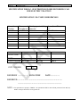


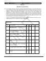
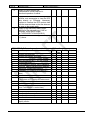
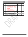
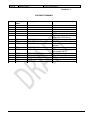
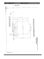


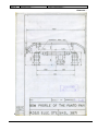
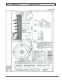
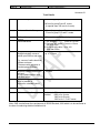
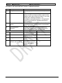
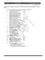
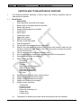


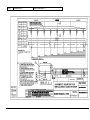

![ステンレスのお手入れ方法-[PDF形式]](http://vs1.manualzilla.com/store/data/006632122_3-4ab279814f324cc6cdce88872ccc19d2-150x150.png)