1
Operator's Manual
Version 2
227 490 02 GA (e)
Revision C
Contents
1
Intended Use and Functional Description
5
2
Controls and Indicators
6
3
Putting the Device into Operation and Performance Check
9
4
Manual Defibrillation
18
4.1
4.2
4.3
18
19
26
Defibrillator Application Guidelines
Non-Synchronized Defibrillation
Synchronized Defibrillation (Cardioversion)
5
Semiautomatic Defibrillation
30
6
Pacemaker
36
7
Displaying and Monitoring the ECG
41
8
12-Lead ECG Analysis Program (12SL
9
Pulse Oximetry (SpO2)
49
10
Capnometry (etCO2)
54
11
Memories of the Marquette Responder® 3000
58
12
Recording
61
13
Defibrillator Setup
63
14
Battery Power Operation
67
15
Test Discharge
70
16
Operation in the Vehicle Mounting Unit,
Mounting the AC Power Adapter
73
17
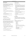
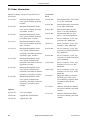
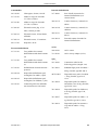
Error and System Messages
74
18
Cleaning, Maintenance
75
19
Technical Specifications
78
20
Order Information
84
TM
)
46
Appendix
The Arrhythmia Detection Program
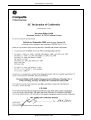
EC Declaration of Conformity
Index
87
88
89
Revision History
This manual is subject to the Marquette Hellige change order service. The revision
code, a letter that follows the document part number, changes with every update of the
manual.
227 490 02-C
P/N / Index
Date
Comment
227 490 02-A
January 1999
Initial Release
227 490 02-B
October 1999
Version 2
227 490 02-C
January 2000
ECO 064 064
Marquette Responder® 3000
3
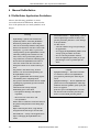
General Information
General Information
The product Marquette Responder 3000 bears
the CE marking
CE-366
indicating its compliance with the provisions
of the Council Directive 93/42/EEC about
medical devices and fulfills the essential requirements of Annex 1 of this directive.
The Marquette Hellige quality management
system complies with the standards DIN EN
ISO 9001 and EN 46001.
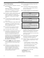
The safety information given in this manual is
classified as follows:
The radio-interference emitted by this device
is within the limits specified in CISPR11/EN
55011, class A.
Warning
indicates a hazard. If not avoided, the hazard can
hazard will result in death or serious injury.
result in death or serious injury.
The device is designed to comply with IEC 60601
requirements. It is a protection class I device
and has an internal power source. It is classified as an MDD class IIb device.
This manual reflects software version 2.
This manual is an integral part of the device. It
should always be kept near the device. Close
observance of the information given in the
manual is a prerequisite for proper device
performance and correct operation and ensures
patient and operator safety. Please note that
information pertinent to several chapters is
given only once. Therefore, carefully read
the manual once in its entirety.
4
Danger
indicates an imminent hazard. If not avoided, the
The CE mark covers only the accessories
listed in the "Order Information" chapter .
On request Marquette Hellige will provide a
service manual.
The product complies with the electromagnetic
immunity requirements of standard IEC
60601-1-2/EN 60601-1-2 "Electromagnetic
Compatibility - Medical Electrical Equipment".
®
The symbol
means: Consult accompanying documents. It indicates points which are of
particular importance in the operation of the
device.
This manual is in conformity with the device
specifications and standards on safety of electromedical equipment valid at the time of
printing. All rights are reserved for devices,
circuits, techniques, software programs, and
names appearing in this manual.
Caution
indicates a potential hazard. If not avoided, this
hazard may result in minor personal injury and/or
product/property damage.
To ensure patient safety, the specified
measuring accuracy, and interference-free
operation, we recommend to use only original
Marquette Hellige components. The user is
responsible for application of accessories from
other manufacturers.
The warranty does not cover damage resulting
from the use of unsuitable accessories and
consumables from other manufacturers.
Marquette Hellige is responsible for the effects
on safety, reliability, and performance of the
device, only if
− assembly operations, extensions, readjustments, modifications, or repairs are carried
out by Marquette Hellige or by persons
authorized by Marquette Hellige,
− the device is used in accordance with the
instructions given in this operator's manual.
Marquette Hellige GmbH 2000
Postfach 600265
79032 Freiburg, Germany
Telephone +49 761 45 43-0
Marquette Responder® 3000
227 490 02-C
Intended Use and Functional Description
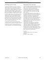
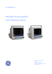
1 Intended Use and Functional Description
The Marquette Responder® 3000 is a lightweight,
portable defibrillator with ECG monitor and
integrated recorder.
It is perfectly geared both to hospital and to
prehospital use; in conjunction with the vehicle
mounting unit, it can also be used in an ambulance.
The color concept for the displayed information
lets you see at a glance whether
− the parameter reading is within the alarm limits
(green),
− a technical fault is reported (blue),
There are two versions of the Marquette
Responder® 3000:
− a version for manual defibrillation,
− a version for semiautomatic defibrillation
which can be switched to manual operation.
− an alarm is reported (red),
Both versions are capable of delivering synchronized and non-synchronized defibrillation shocks.
− an event memory,
The following paddle types can be used with the
defibrillator: hard paddles (with integrated contact
surfaces for children), adhesive electrodes and
internal spoons.
The device features can be upgraded with the
following options:
− a program for ECG measurement and interpretation (12SL),
− an etCO2 measurement system (capnometry),
− an SpO2 measurement system (pulse oximetry),
− a transcutaneous pacemaker.
− the system displays a message (yellow).
The defibrillator has the following memories for
storage and documentation of the relevant
procedure data:
− an ECG memory,
− a trend memory, and
− a memory for the 12SL analysis results.
The integrated 3-channel recorder can be started
manually and automatically.
The defibrillator is powered from
− an optional AC power adapter which is
permanently attached to the defibrillator, or
− 1 or 2 plug-in batteries, or
− the vehicle mounting unit / wall mount unit.
Batteries are recharged via:
− the optional AC power adapter
1
2
− the optional charging unit, or
3
− the optional vehicle mounting system.
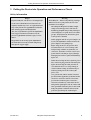
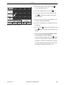
1
Pacer
On
Off
10
Dem
Fix
20 30
7
5
2
Autoseq
Start
Pause
P/min
+
Biocompatibility
The parts of the product described in this operator
2
Sync
—
manual, including all accessories, that come in
Analyse
mA
+
50
100
150
200
300
360
contact with the patient during the intended use,
—
3
fulfill the biocompatibility requirements of the appliPrint
Event
cable standards. If you have questions in this matter,
please contact Marquette Hellige GmbH or its representatives.
Figure 1-1.
227 490 02-C
Marquette Responder® 3000
Marquette Responder® 3000
5
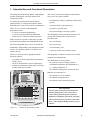
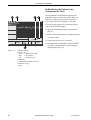
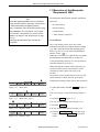
Controls and Indicators
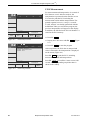
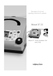
2 Controls and Indicators
The Device
1
31
1
30
29
28
27
26
25
24
23
22
21
20
19
18
17
2
6
3
3
4
1
Pacer
10
20 30
7
On
Off
5
2
Autoseq
Dem
Fix
Start
Pause
+
50
100
150
200
300
360
2
P/min
Sync
—
Analyse
mA
+
—
3
Print
16
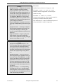
Figure 2-1.
2
Event
15
5
6
7
8
9
10
11
14 13 12
Controls and indicators of the Marquette Responder® 3000
Marquette Responder® 3000
227 490 02-C
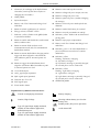
Controls and Indicators
1
Connector for exchange of the defibrillation
electrodes (switch off the device before exchanging the electrodes!)
18 Button to start and stop the recorder
19 Button to change the pacer output (current)
20 Button to change the pacer rate
2
APEX paddle
3
Infrared interface
21 Button to pause the pacer (without changing
the settings)
4
Battery with "Test" button and charge level
indication
22 Button to select the pacer mode (fixed rate,
demand)
5
Button to unlock right battery for removal
23 Button to unlock left battery for removal
6
Energy selector, ON/OFF switch
24 Button to turn the pacemaker on and off
7
Indicator, yellow, flashes to the QRS rhythm
in synchronized mode
25 Indicator, yellow: blinks with each delivered
pacing pulse
8
Button to enable and disable the synchronized
mode (cardioversion)
26 Button to open paper compartment
9
Button to initiate ECG analysis in the
semiautomatic mode (only on semiautomatic
defibrillator models)
10 Button to initiate defibrillator charging and to
trigger the shock (together with button 11)
when adhesive pads or internal spoons are
used
11 Button to trigger the defibrillation shock
(together with button 10) when adhesive pads
or internal spoons are used
12 1-Volt ECG output
13 etCO2 signal input (optional)
14 SpO2 signal input (optional)
15 Function keys F1 to F5
27 Battery with "Test" button and charge level
indication
28 Indicator, green: is lit when defibrillator is
powered from an external source (mains,
ambulance)
29 Indicator, yellow
blinking: left battery charging
on: left battery charged
off: left battery missing or partially charged,
no external power source connected
30 Indicator, yellow
blinking: right battery charging
on: right battery charged
off: right battery missing or partially charged,
no external power source connected
31 STERNUM paddle
16 ECG signal input
17 Event marker button
Explanation of symbols used on the device
Battery charging
Consult accompanying documents
Caution, High Voltage
+
Type CF signal input: highly insulated,
suitable for intracardiac application,
defibrillation-proof
Type CF signal input: highly insulated,
suitable for intracardiac application
227 490 02-C
Housing without battery (to close the
battery slot)
Standby mode (line power operation)
Audio alarm OFF
Marquette Responder® 3000
7
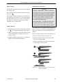
Defibrillation Electrodes
Defibrillation Electrodes
Hard Paddles
a
CHARGE SHOCK
3
2
APEX
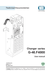
Figure 2-2.
Hard paddle
c b
Hard paddles are the electrodes commonly used
for external, transchest defibrillation. There is a
special Apex paddle and a Sternum paddle.
For delivery of the defibrillation shock, the
paddles are placed directly on the body surface.
Before use, however, an ample amount of
electrode gel must be spread onto the paddles.
Both paddles have a shock button: The shock
button on the Apex paddle is used to initiate
defibrillator charging; afterwards the defibrillation
shock is triggered by pushing both shock buttons.
The paddles can also be used to acquire the ECG
signal.
A smaller contact surface for defibrillation of
children is integrated in the paddles (see "Defibrillation of Children" in section 4.2).
Electrodes for Internal Defibrillation
d
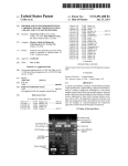
Figure 2-3.
Electrode for internal defibrillation
Electrodes for internal defibrillation consist of a
contact spoon (a, Figure 2-3), a handle b, and a
counter nut c.
The spoon must match the size of the heart and
have full contact with the myocardium. There is a
choice of 3 different spoon sizes.
The electrodes as well as their connection cable
must be sterilized before each use.
An internal defibrillation is either performed with
two spoon electrodes or with one spoon electrode
and a so-called "external counter electrode" (d,
Figure 2-3) which is placed under the patient and
in the immediate vicinity of the heart.
Defibrillator charging and release of the defibrillation shock are initiated with buttons on the
device.
Disposable Adhesive Electrodes
Figure 2-4.
8
Disposable adhesive electrode
(external defibrillation, pacing)
Disposable adhesive electrodes are used both for
defibrillation and for pacing. These electrodes are
self-adhesive and pregelled. They are connected by
means of a special cable and may remain attached
to the patient for a maximum of 24 hours.
Marquette Responder® 3000
227 490 02-C
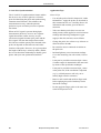
Putting the Device Into Operation and Performance Check
3 Putting the Device into Operation and Performance Check
Safety information
Danger
Warning
Explosion Hazard – The device is not designed for
Shock Hazard — Observe the following warnings.
use in areas of medically used rooms where an
Otherwise the lives of the patient, the user and
explosion hazard may occur. An explosion hazard
bystanders are in danger.
The Marquette Responder® 3000 is a highvoltage electrotherapy device and must be
handled by qualified and specially trained personnel. Improper use of the device can endanger life. Always follow the instructions given
in the operator's manual.
may result from the use of flammable anesthetics,
skin cleansing agents and disinfectants.
Also, it is not permitted to operate the defibrillator
in an oxygen-enriched environment or in the
presence of flammable substances (gas) or anesthetics.
Oxygenation in the vicinity of the defibrillation
-
When equipped with the AC power adapter, do
not use the defibrillator outdoors because the
power adapter is not splash-proof.
-
Before using the device, the operator must
ascertain that it is in correct working order
and operating condition. In particular, all
connectors, electrodes as well as sensors and
probes must be checked for signs of damage.
Damaged parts must be replaced immediately,
before use.
-
When disconnecting the device from the power
line, remove the plug from the wall outlet first,
before disconnecting the cable from the device. Otherwise there is a risk of coming in
contact with line voltage by inadvertently introducing metal parts in the socket of the
power cord.
-
As a general rule, utmost caution is advised
for intracardiac application of medical technical devices. Great care must be exercised to
prevent that conductive parts (connectors,
electrodes, transducers) connected to the isolated patient signal input come in contact with
other grounded conductive parts, as this could
bridge the patient's isolation and cancel the
protection provided by the isolated input.
electrodes must be strictly avoided. Temporarily
interrupt the oxygen supply.
227 490 02-C
Marquette Responder® 3000
9
Putting the Device Into Operation and Performance Check
-
Electrically conductive contact with parts
connected to the heart (pressure transducers,
metal tube connections and cocks, guide
wires, electrode catheters and the metal parts
of syringes) must be avoided at all cost.
When using devices intracardially, observe
these guidelines:
-
always wear isolating rubber gloves;
-
parts with a conductive connection to the
heart must be isolated from ground;
-
do not use tube fittings and stopcocks made
of metal, if possible;
-
when connecting the heart catheter, observe
these guidelines:
- the connection must be isolated
- all electrodes must be attached to the patient and secured against inadvertent disconnection or they must be isolated and
protected against inadvertent contact (otherwise electrodes that become disconnected
could bring the patient in contact with
ground).
-
When devices are used intracardially, the
annual Technical Inspections are mandatory.
During intracardiac application of medical
electrical devices, a defibrillator and pacemaker, both checked for proper functioning,
must be readily available.
-
Ensure that no conductive connection between
the patient and bystanders exists during defibrillation.
10
-
The mains plug must be connected to an
appropriate power supply with a non-fused
earthed wire. If these requirements cannot be
guaranteed, connect the device to the ambulance power supply or operate it on battery
power.
-
Do not use multiple portable socket outlets
(MPSO) to connect the device to the power
line.
-
Devices may be connected to other devices or
to parts of systems only when it has been made
certain that there is no danger to the patient,
the operators, or the environment as a result.
In those instances where there is any element
of doubt concerning the safety of connected
devices, the user must contact the manufacturers concerned or other informed experts as
to whether there is any possible danger to the
patient, the operator, or the environment as a
result of the proposed combination of devices.
Standards IEC 60601-1-1/EN60601-1-1 must
be complied with in all cases.
-
The device (without AC power adapter) is
suitable for application in a humid environment provided the regulations concerning
drip-proof equipment of IEC 60601/EN 60601
are strictly observed. However, do not defibrillate patients in a very moist or wet environment, unless absolutely necessary. Always
dry the defibrillation electrodes and connection cables prior to defibrillation.
Marquette Responder® 3000
227 490 02-C
Putting the Device Into Operation and Performance Check
-
Warning
Equipment Failure — Magnetic and electrical
fields are capable of interfering with the
proper performance of the device. For this
reason make sure that all external devices operated in the vicinity of the defibrillator comply with the relevant EMC requirements. Xray equipment, MRI devices, radio systems,
and cellular telephones are a possible source
of interference as they may emit higher levels
of electromagnetic radiation.
Keep the defibrillator away from these devices
and verify the defibrillator performance before
use.
-
Equipment Failure — Similarly, the defibrillator may disturb equipment operating in its
vicinity when charging or delivering the
shock. Verify the performance of these devices
before use.
-
Suffocation Hazard — Dispose of the packaging material, observing the applicable
waste-control regulations. Keep the packaging
material out of children's reach.
-
Literature
Medical Device Directive of August 2, 1994
EN 60601-1: 1990 + A 1: 1993 + A 2: 1995
Medical electrical equipment. General requirements for safety.
EN 60601-1-1: 9/1994 + A1: 12/1995
General requirements for safety. Requirements for
the safety of medical electrical systems.
IEC-Publication 513/1994: Fundamental aspects of
safety standards for medical equipment.
Caution
Equipment Damage, Shock Hazard — Devices intended for emergency application must
not be exposed to low temperatures during
storage and transport to avoid moisture condensation at the application site. Wait until all
moisture has vaporized before using the device.
-
Equipment Damage — Exercise great care
when using HF surgery equipment on the patient at the same as the defibrillator. As a general rule, the distance between the ECG and
defibrillation electrodes and the HF surgery
electrodes should not be less than 15 cm. If
this is not ensured, disconnect the electrodes
and transducer leads while using the HF surgery device.
-
Equipment Damage — Avoid defibrillating
repeatedly into open air or with the paddles
shorted together, because the device temperature may increase to an inadmissible level due
to the internal safety discharges.
227 490 02-C
Marquette Responder® 3000
11
Putting the Device Into Operation and Performance Check
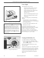
Power Supply
The defibrillator can be powered
− from the power line (requires AC power
adapter, P/N 205 108 01, Figure 3-1),
− from the ambulance power supply system
(requires vehicle mounting unit,
P/N 202 317 01),
− from the wall mount unit (P/N 202 317 03)
− from 1 or 2 rechargeable batteries (mainsindependent).
Batteries are recharged by one of the following
methods:
Figure 3-1.
Defibrillator with AC power adapter
− in the defibrillator, when the defibrillator is
connected to the power line or to the ambulance
power supply system, or
− by means of the separate charging unit ASU
3000 (P/N 701 279 01).
Note
The Marquette Responder® 3000 is switched on
and off with the energy selector. Once you are
familiar with the device operating routines, this
If you prefer to operate the device mainsindependent, ensure that the batteries are charged
(chapter 14 "Battery Power Operation").
control lets you turn on the device and select the
required defibrillation energy in one action. No
shock can be delivered in the
position of the
energy selector.
Turning the Defibrillator On
1
10
7
5
2
Autoseq
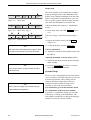
Figure 3-2.
Please refer to chapter 16 for information on
operating the device in the vehicle mounting unit
and on installing the AC power adapter.
20 30
50
100
150
200
300
360
Turning the defibrillator on
•
•
Connect the device to the power supply.
Switch on the device by turning the energy
(defibrillation shocks cannot be
selector to
delivered in this position).
The test screen appears and the device emits a
short audio signal.
On the test screen you can see the software version
and a message referring to the self-test. The three
color blocks in red, green and blue are displayed to
verify the correct representation of the colors.
After the self-test the standard screen appears
(Figure 3-3).
12
Marquette Responder® 3000
227 490 02-C
Putting the Device Into Operation and Performance Check
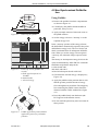
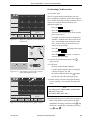
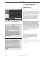
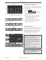
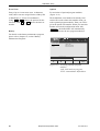
The Standard Screen Display
a b
Electrode
c
0
f
This is the information presented on the standard
screen display:
− windows for heart / pulse rate, SpO2 and etCO2
readings including the limit values a, b
Paddle
160 / 40
ECG
d e
bpm
SpO2
parameter
window
− battery charge level c
− ECG lead d
etCO2
parameter
window
− window for ECG, SpO2 and etCO2 waveforms
pacemaker
window
15.07.1999
09:05:00
semiautom.
ECG
SpO2
etCO2
QRSPulse
Tone
OFF
Next
Menu
The color concept for the displayed information
lets you see at a glance whether
Standard screen display
b selected limit values
− the parameter reading is within the alarm limits
(green),
c battery charge level indication
− a technical fault is reported (blue),
d ECG lead (ECG signal acquired
via "Paddle")
− an alarm is reported (red),
a measured heart rate/pulse rate
e date, time
f selected operating mode,
defibrillation energy
g menu
227 490 02-C
− date and time e
− menu g.
g
Figure 3-3.
− window indicating operating mode and
defibrillation energy f
− the system displays a message (yellow).
If the device does not receive an ECG signal, the
HR window is blue (technical fault) and a
sawtooth signal is displayed instead of an ECG.
The SpO2 and etCO2 parameter windows are also
blank and the corresponding waveforms are
missing when the required sensors are not
connected.
Marquette Responder® 3000
13
Putting the Device Into Operation and Performance Check
Display Flip
↓
ECG
SpO2
etCO2
Figure 3-4.
QRSPulse
Tone
OFF
Next
Menu
Main menu
↓
Filter
ON
Assign
Channel
Waveform
Figure 3-5.
↓
Contrast
Figure 3-6.
Memory
Display
Previous
Menu
•
Main menu, page 2
↓
Contrast
The screen display can be rotated 180° to adapt it
to the operating position of the defibrillator. The
display can be flipped permanently from the setup
menu or temporarily as outlined below. You can
also set up the system to flip the display automatically when the defibrillator is inserted in the
vehicle mounting unit (chapter 13 "Defibrillator
Setup").
↓
Select
Color
Display
Flip
Previous
Menu
•
Note
Next Menu
(Figure
You will see page 2 of the main menu (Figure 35).
•
Display menu
In the main menu, select F5
3-4).
Display the Display menu with F4
(Figure 3-6).
To flip the display, press F4
The main menu will automatically reappear, when
Contrast adjustment
no button is activated for a period of 30 seconds.
•
Display
Display Flip
.
Adjust the contrast from the Display menu with
F1 and F2.
Adjusting Maximum Contrast (Select Color)
•
•
Note
Press F5 for about 2 seconds to return directly to
the main menu.
Press F5 Previous Menu for about 2 seconds to
return directly to the main menu.
System Setup
Note
Enter your own settings in the column at the far
right (with date and signature).
14
Adjust the maximum contrast from the Display
menu with F3.
The device has a configuration menu which allows
you to customize some of the functions to suit your
personal requirements. These settings will be
retained. The table at right shows all device
settings for which customer defaults can be
selected, as well as the factory defaults.
The information given in this manual is based
on a defibrillator with the factory defaults.
In chapter 13 "Defibrillator Setup" you will find
instructions on setting up the defibrillator. The
same chapter explains how to change the language
and how to restore the factory defaults.
Marquette Responder® 3000
227 490 02-C
Putting the Device Into Operation and Performance Check
Parameter
Comment
Factory
Defaults
Options
User Setup
HR Limit
40/160
OFF, 15 to 300
increments of 5
SpO2 Limit
---/90
OFF, 60 to 99
etCO2 Limit
---/20
OFF, 5 to 76
increments of 1
ALARM LIMITS
ECG
Print on Alarm
autom. recorder start on violation of limit
value
off
on/off
Lead Fail Alarm
audio signal indicating disconnected
electrode
off
30 s/off
Alarm Tone
audio signal indicating violation of an
alarm limit
off
on/off
off
low/middle/high / off
QRS Beep
Muscle Filter
suppression of motion artifact
on
on/off
Gain
for ECG display
1 cm/mV
0.5; 1; 2 cm/mV
Lead Channel 1
I
standard leads,
paddle acquisition
Lead Channel 2
II
standard leads, SpO2
Lead Channel 3
III
standard leads, SpO2,
etCO2
on/off
DEFIB
Print on shock
automatic recorder start on shock
on
Operating Mode**
choice of the operating mode
semiautomatic/button semiautom./button
semiautom./password
semiautom.
manual
Autosequence
energy selection
200 J, 200 J, 360 J
150 to 360 J per shock
Pacemaker
default pacer rate
60 P/min
30 to 200 P/min
C-LOCK
C-Lock ECG synchronization
off
on/off
SpO2 Integ. Time
SpO2 integration time
8s
4 s, 8 s, 12 s
DATE/TIME**
Change clears all existing settings.
day.mon.year
day.mon.year
mon/day/year
SpO2
Date Format**
Entry of date and time
DEVICE
Display
screen display (SmartFlip = display flips normal
automatically when defibrillator is placed
in vehicle mounting unit)
normal, reverse,
SmartFlip
Volume
valid for all audio signals
high
high/low/middle
Cont. Printout
continuous recording or 14-second strip
off
on/off
Analysis
continuous ECG analysis
on
on/off
AC Line Filter**
elimination of AC line interference
50 Hz
off/50 Hz/60 Hz
Language**
selection of the language
Factory Default
restores factory defaults
User**
text or name (20 characters)
PASSWORD**
entry of the password
111
000/999
for config**
protects access to configuration menu
off
on/off
EVENT TEXTS**
entry of event texts
BATTERY
battery maintenance program
OPTIONS
entry of option code to unlock option
on/off
** not affected by reactivation of factory defaults
227 490 02-C
Marquette Responder® 3000
15
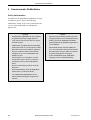
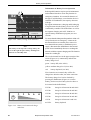
Putting the Device Into Operation and Performance Test
Performance Check
A performance check must be carried out before
each use.
Electrode
160 / 40
ECG
Paddle
The check includes:
bpm
− a visual inspection of the device, the cables and
the electrodes for signs of mechanical damage,
− verification of the functional readiness of the
device,
− delivery of a test discharge.
15.07.1999
09:05:00
semiautom.
SpO2
etCO2
ECG
Figure 3-7.
QRSPulse
Tone
OFF
Next
Menu
Standard screen display of a
defibrillator ready for operation (no
ECG, SpO2 and etCO2 signal available)
After power-up and during operation, the
Marquette Responder® 3000 runs automatic selftests. If malfunctions are identified, an error
message will be displayed (see chapter 17 "Error
and System Messages"). In this situation do not
put the device into service.
In all other cases you will see the standard screen
display (Figure 3-7) and the device is ready for
use.
Note
A special simulator is required to test the defibrillator performance in the semiautomatic mode.
Now verify that the defibrillation shock is
correctly delivered by triggering a test discharge
(chapter 15 "Test Discharge").
If the energy of the test discharge is not within the
specified limits, a defibrillation is possible all the
same (it is the user's decision whether or not to
employ the defibrillator). However, the device
must be immediately checked and repaired by a
service technician.
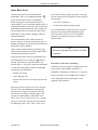
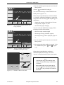
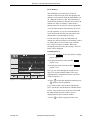
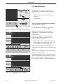
Event Button
62
160 / 40
ECG
Event
I
bpm
II
III
15.07.1998
Text 1
Figure 3-8.
16
You can use the
button to mark specific
events (e.g. administration of medications). When
you press this key, the corresponding point in time
is earmarked in the full-disclosure ECG. Furthermore, you can assign a maximum of 8 "event"
texts to the function keys F1 to F4 (e.g. names of
medications). When you press
these texts
appear in the menu line (Figure 3-8). You can
press one of the function keys to assign the
corresponding text to the event. With F5 Next Menu
you can display the next line of 4 texts. (Refer to
chapter 13 "Device Setup" for instructions on
entering event texts.)
Text 2
Event
09:05:00
Text 3
Event texts
semiautom.
Next
Text 4
Menu
Marquette Responder® 3000
227 490 02-C
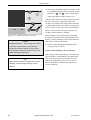
Putting the Device Into Operation and Performance Test
How to toggle the defibrillator from
semiautomatic to manual operation
2
Sync
Analyse
Depending on their setup, semiautomatic defibrillators can be switched to manual control. The
defibrillator can be set up for four different modes
of operation:
− semiautom./button (switching to manual mode
by activating button)
3
− semiautom./password (switching to manual
mode by activating button and entering password)
− semiautomatic (manual control not possible)
− manual (only manual control possible)
Figure 3-9.
Electrode
Buttons to activate the manual mode
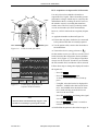
Operating Mode "semiautomatic/button"
0
•
Paddle
160 / 40
ECG
bpm
To activate the manual mode, simultaneously
(Figure 3-9).
press F5 and
Analyse
15.07.1998
When switched on again, the defibrillator will
reactivate the operating mode selected in the setup
menu.
Date and time of the change of operating modes is
stored in the event memory.
09:05:00
semiautom.
0
0
0
ENTER
Operating Mode "semiautomatic/password"
•
To activate the manual mode, simultaneously
(Figure 3-9).
press F5 and
Analyse
Figure 3-10. Buttons for entry of the password
0
•
Paddle
160 / 40
ECG
bpm
15.07.1998
09:05:00
manual
ECG
etCO2
SpO2
QRSPulse
Tone
OFF
Next
Menu
Figure 3-11. Defibrillator set up for manual
operation
227 490 02-C
The screen for entry of the password appears
(Figure 3-10).
Enter the password (3-digit number) with F1,
F2, F3. The factory-set password is 111 (also
refer to chapter 13, section "Password").
When switched on again, the defibrillator will
reactivate the operating mode selected in the setup
menu.
Date and time of the change of operating modes is
stored in the event memory (chapter 11 "Memories
of the Marquette Responder® 3000").
If you wish to return to the semiautomatic mode,
you will have to turn the device off and on again.
Marquette Responder® 3000
17
Manual Defibrillation / Non-Synchronized Defibrillation
4 Manual Defibrillation
4.1 Defibrillator Application Guidelines
Observe the following guidelines to ensure
successful and safe defibrillation. Otherwise the
lives of the patient, the user and bystanders are in
danger.
Warning
-
-
Defibrillating a patient with normal heart
rhythm may induce ventricular fibrillation.
-
Position the patient flat on a hard surface
where he is electrically insulated. The patient
must not be allowed to come into contact with
metal parts, e.g., bed or litter, to prevent unwanted pathways for the defibrillation current
which may endanger the assistants. For the
same reason, do not position the patient on
wet ground (rain, accident in swimming pool).
Do not allow the defibrillation electrodes to
come into contact with other electrodes or
metal parts which are in contact with the patient.
The patient's chest must be dry, because
moisture can cause unwanted pathways for
the defibrillation current.
After use of flammable skin cleansing agents,
wait until they have completely dried.
-
The operator and all assistants must be briefed
regarding the preparations for and execution
of defibrillation.
All tasks must be clearly assigned.
Immediately prior to the shock
- interrupt heart massage and artificial
respiration,
- disconnect tube connections, and
- warn bystanders.
-
Ensure that no conductive connection between
the patient and bystanders exists during defibrillation.
-
Before delivering the shock, verify that the
charged and selected energies are the same.
-
Shock Hazard — Always switch off the device
before exchanging the defibrillation electrodes.
18
Pacemaker Patients — Defibrillating a patient
with an implanted pacemaker is likely to impair the pacemaker function or cause damage
to the pacemaker.
For this reason
- select the smallest energy level possible for
the application,
- do not apply the defibrillation paddles in the
vicinity of the pacemaker electrodes,
- have an external pacemaker at hand,
- check the implanted pacemaker for proper
functioning as soon as possible after the
shock.
Caution
-
Equipment Damage — Disconnect transducers and devices that are not defibrillationproof from the patient before delivering the
shock.
-
Equipment Damage — Do not defibrillate the
patient with a second defibrillator, while defibrillation electrodes (paddles, pads) of the first
device are applied.
If the use of a second defibrillator is inevitable, disconnect the electrodes from the first
device or remove them from the patient.
Marquette Responder® 3000
227 490 02-C
Manual Defibrillation / Non-Synchronized Defibrillation
4.2 Non-Synchronized Defibrillation
Using Paddles
•
•
•
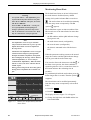
Figure 4-1.
Removing the paddles
a
0
c
Paddle
160 / 40
ECG
b
bpm
15.07.1999
ECG
09:05:00
QRSPulse
Tone
OFF
SpO2
etCO2
Figure 4-2.
200 J
manual
Next
Menu
Power-up screen (paddles connected)
a ECG signal acquired via
"Paddle"
b manual mode
c selected energy
•
•
•
M
NU
ER
ST
K
OC
SH 3
•
AR
2 GE
SH
AP
EX
Figure 4-3.
227 490 02-C
O
3 CK
Carefully dry the paddles and the handles in
particular, if they are wet.
Apply an ample amount of electrode cream to
the paddle surfaces.
Set the energy selector to "Autoseq" or to the
required energy level.
In the "Autoseq" position of the energy selector,
the defibrillator automatically sequences the preset
defibrillation energy levels. The level for the 3rd
shock is maintained for all subsequent defibrillations. When you set the energy selector again to
"Autoseq", the automatic charge sequence starts
over.
The factory set Autosequence energy levels are the
values recommended by AHA/ERC for ventricular
fibrillation and pulseless tachycardia.
1st shock with 200 J
2nd shock with 200 J
3rd and all subsequent shocks with 360 J.
•
CH
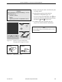
Remove the paddles from their compartments
as shown in Figure 4-1.
Check that the selected energy is displayed (c,
Figure 4-2).
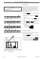
Apply the paddles on the patient's thorax such
that the greatest possible amount of energy
flows through the myocardium. The imaginary
line connecting the paddle centers should be
identical with the cardiac median line (Figure
4-3).
Press the paddles firmly onto the thorax (the
ECG appears on the monitor screen).
Do not touch the patient any more and warn all
those present.
Paddle application points (dashed
application points for pacemaker
patients)
Marquette Responder® 3000
19
Manual Defibrillation / Non-synchronized Defibrillation
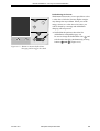
•
a
b
Initiate energy storage with the button on the
APEX paddle (a).
When the selected energy is stored,
SHOCK
3
STERNUM
CHARGE SHOCK
2
3
− the device emits an audio signal
− the message "Energy available" appears,
− the available energy is displayed (if the
available energy drops below a given level, the
defibrillator recharges automatically).
APEX
•
Now trigger the shock within 30 seconds. To do
so, simultaneously press the buttons a and b on
the paddles.
After the shock
Figure 4-4.
Buttons to initiate defibrillator
charging (a) and to trigger the shock
(a+b)
Warning
Risk of Skin Burns / Equipment Damage — Do
not apply the paddles over
-
sternum or clavicle,
-
nipples
-
implanted pacemaker or defibrillator devices.
Note
− If you do not trigger the shock within 30 seconds of charging, the energy will automatically
be discharged internally. You will then have to
recharge the defibrillator.
− When the defibrillator is charged, you can
increase and decrease the energy level to any
value with the energy selector (without pressing
the "Charge" button again).
For an internal discharge of the stored energy,
set the energy selector to
or to "Off".
20
− the audio signal stops and the delivered energy
is displayed for approx. 6 seconds (in place of
the available energy),
− the recorder prints a 14-second ECG strip (4
seconds before the shock, 5 seconds blanked,
10 seconds after the shock) (configurable); the
blanked period of time is indicated by a vertical
line on the recording;
− the shock delivery is annotated on the stored
ECG (also refer to chapter 11 "Memories of the
Marquette Responder® 3000").
If the defibrillator cannot store the selected energy
so that selected and stored energy values differ, a
warning will be displayed. The defibrillation pulse
can be triggered all the same.
In this situation we recommend to check the
batteries first. If the batteries are intact, have the
defibrillator immediately repaired.
Marquette Responder® 3000
227 490 02-C
Manual Defibrillation / Non-Synchronized Defibrillation
Shock Counter
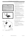
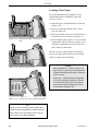
Defibrillation of Children
The number of delivered shocks is indicated below
the energy value.
Warning
Damage to Myocardium — Please note that chil-
This counter is reset to 0 when you set the energy
.
selector to
dren require less energy for successful ventricular
defibrillation than adults. For the first defibrillation shock delivered to babies and small children,
The number of delivered shocks is also shown on
the recording strip (Figure 5-5, intervention report
d). This counter, however, counts all shocks since
the device was turned on and is reset to 0 only
when the device is turned OFF.
select an energy of approx. 2 J/kg body weight.
For subsequent shocks, the energy may be increased to 4 J/kg body weight.
Risk of Skin Burns — The full electrode must be
in contact with the skin surface (use the small
contact surface of the paddles / pads for children).
Ending Therapy
•
•
•
Once therapy has ended, set the energy selector
for continued monitoring of the patient.
to
If there is no need to monitor the patient, switch
off the defibrillator by setting the energy selector to "Off".
Clean the paddles and the device as outlined in
chapter 18 "Cleaning, Maintenance".
The paddles have two different contact surfaces; a
large one (can be removed) for the defibrillation of
adults and a smaller one for the defibrillation of
children.
Remove the large contact surface for pediatric use:
•
•
•
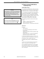
Press on the lock button 1 (Figure 4-5).
Slide the contact surface 2 towards the front
and take it off the paddle.
When re-installing it, the large contact surface
must audibly click into place.
1
2
Figure 4-5.
227 490 02-C
Marquette Responder® 3000
Removing the large contact surface
from the paddles
21
Manual Defibrillation / Non-synchronized Defibrillation
Using Disposable Defibrillation Pads
− Use pads before their expiration date.
− Do not reuse the pads.
Danger
Shock Hazard — For defibrillation with disposable adhesive electrodes, the paddles including
their leads must be replaced with the adapter cable
223 383 01. Switch off the defibrillator before
exchanging the lead. Also, the defibrillator must
be switched off when the adapter cable is connected to the pads.
− A pair of pads may remain attached to the
patient for up to 24 hours and withstands up to
50 shocks of 360 J each.
− Use electrodes 919 202 94 for adults and
electrodes 919 202 95 for children.
− Shave the application points; this improves
conductivity and makes removal of the pads
easier.
STERNUM: right sternal edge at the level of
the 2nd intercostal space,
APEX: left axillary line at the level of the 5th
intercostal space (Figure 4-7).
− Place the pads on the patient such that the
connectors point to either side of the patient
and that the cables are not hindering patient
treatment.
Figure 4-6.
− The electrodes are pregelled; therefore, do not
use additional contact cream or gel.
Connecting the lead
− Do not use pads, if the gel is dry.
•
•
STERNUM
electrode and connector
•
•
Rub the patient's chest dry.
Press the connector of the lead on to the
electrode contact pin until you hear it click into
place (Figure 4-6).
Peel off the backing from each pad.
Press the pads carefully on the appropriate
sites, observing the APEX and STERNUM
labels (Figure 4-7).
APEX
electrode and connector
Figure 4-7.
22
Defibrillation pad application points
(anterior - anterior)
Marquette Responder® 3000
227 490 02-C
Manual Defibrillation / Non-Synchronized Defibrillation
•
Warning
Risk of Skin Burns / Equipment Damage — Do not
attach the pads over
-
sternum or clavicle
-
nipples
-
implanted pacemaker or defibrillator devices.
•
•
Before delivering the shock, check that the pads
are firmly seated.
Defibrillate the patient as described for
defibrillation with paddles (page 19).
and
Be sure to charge the defibrillator with
to deliver the shock by simultaneously pressing
and
(Figure 4-8).
the buttons
Carefully remove the electrodes after use
(Figure 4-9) and discard them immediately.
2
Sync
Note
Analyse
Discard disposable pads immediately after use. Do
not reuse them.
3
Figure 4-8.
wrong
Figure 4-9.
227 490 02-C
Buttons to initiate defibrillator
charging and to trigger the shock
correct
Removing the pads
Marquette Responder® 3000
23
Manual Defibrillation / Non-synchronized Defibrillation
Using Internal Defibrillation Electrodes
Warning
Note
If you are using internal electrodes with the
Shock Hazard – Always switch off the device
Marquette Responder® 3000, defibrillator charg-
before exchanging the defibrillation electrodes
ing must be initiated with button
and internal spoons.
and the
shock is delivered by simultaneously pressing
buttons
and
Spoon-shaped electrodes are used for internal
defibrillation. Their contact surface must match
the dimensions of the heart. The spoons must make
full contact with the heart. There is a choice of 3
different spoon sizes. You can use either two
spoon electrodes or one spoon electrode and one
external counter electrode for defibrillation
(Figure 4-10, chapter 20 "Order Information").
Sterilize internal electrodes before each use
(chapter 18 "Cleaning, Maintenance").
.
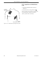
Figure 4-10. External counter electrode
Inserting the Spoon Electrode
•
•
Figure 4-11. Inserting the spoon electrode
•
24
Screw the counter nut 2 (Figure 4-11) onto the
electrode as far as it will go.
Screw the contact paddle 1 into the handle as
far as it will go, then bring it into the appropriate position.
Now fix the contact paddle by screwing the
counter nut 2 tight against the handle 3.
Marquette Responder® 3000
227 490 02-C
Manual Defibrillation / Non-Synchronized Defibrillation
Defibrillating the Patient
2
Sync
Analyse
With internal electrodes, it is not possible to select
a value above 50 Joules, because higher energies
may damage the myocardium. When you set the
energy selector to a value above 50 Joules, you
will be alerted by a message and defibrillator
charging will not proceed.
•
3
Defibrillate the patient as described for
defibrillation with paddles (page 19).
Be sure to charge the defibrillator with
and
to deliver the shock by simultaneously pressing
and
(Figure 4-12).
buttons
Figure 4-12. Buttons to initiate defibrillator
charging and to trigger the shock
227 490 02-C
Marquette Responder® 3000
25
Manual Defibrillation / Synchronized Defibrillation
4.3 Synchronized Defibrillation
(Cardioversion)
Some Basic Facts
Warning
False Triggering — Do not use a pacemaker ECG
for triggering, because the trigger pulses derived
from pacemaker ECGs may be incorrect and
synchronized delivery of the defibrillation shock
may not be possible.
Note
After each synchronized defibrillation, the device
reverts to the non-synchronized mode; the same
applies when the energy selector is set to
.
For synchronized defibrillation (cardioversion) the
defibrillation shock is delivered in synchronization
with the heart action, as the heart is still working.
As a prerequisite, the patient's ECG signal must be
supplied to the defibrillator. After the attending
physician has given the "defibrillation command"
by pressing the appropriate buttons, the device will
wait for the next QRS complex to derive the
trigger signal for actual delivery of the shock.
The following electrodes can be used for cardioversion:
− paddles (+ separate ECG electrodes),
− adhesive electrodes (pads), or
− internal electrodes (+ separate ECG electrodes).
Indications
Examples
− mitral stenosis
− left ventricular hypertrophy (aortic stenosis,
hypertension)
− impaired myocardiac function (ischemia, right
heart failure)
− patients with atrial or ventricular arrhythmias,
hypotension and/or pulmonary edema.
If ventricular fibrillation develops, select the nonsynchronized mode for defibrillation, because it is
not possible to detect a QRS complex for
triggering in the presence of ventricular fibrillation.
Cardioversion with the Marquette Responder®
3000 is only possible in the manual mode.
We recommend acquiring the ECG with separate
ECG electrodes. However, you can also defibrillate the patient with adhesive pads and pick up the
ECG via the pads.
26
Marquette Responder® 3000
227 490 02-C
Manual Defibrillation / Synchronized Defibrillation
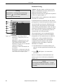
ECG Acquisition via Separate ECG
Electrodes and Patient Cable
red
yellow
R
L
white
C
Use only silver/silver-chloride electrodes to
acquire the ECG signal. These electrodes prevent
polarization voltages which may be caused by the
defibrillation shock, resulting in an ECG trace on
the monitor screen or recording that simulates
cardiac arrest. The ECG can be picked up with 5
or with 10 electrodes (for ECG measurement,
however, 10 ECG electrodes are required (chapter
8)).
•
•
black
N
F
green
•
Figure 4-13. ECG electrode placement
•
Apply the electrodes as shown in Figure 4-13.
Plug the block of leadwires (N, R, L, F, C1)
into the patient cable (Figure 4-14).
Connect the patient cable to the device (Figure
4-15).
Turn on the device (energy selector to
).
On the monitor screen you will now see the 3 ECG
leads selected in the setup menu (factory defaults:
leads I, II, III).
Warning
Shock Hazard / Equipment Damage — All patient
Figure 4-14. Connecting the electrode leads to
the patient cable
signal inputs labeled with the
symbol are
protected against damage resulting from defibrillation and electrocautery voltages. For this reason,
Print
Event
patient safety and device protection are ensured
during defibrillation and HF surgery.
Nevertheless, extreme care should be exercised when
electrosurgery devices are used on a patient who is
connected to other devices. As a general rule, a
minimum distance of 15 cm between the ECG and
electrosurgery electrodes should be maintained. If
this is not ensured, temporarily disconnect the electrodes and transducer leads while using the electrosurgery device.
Figure 4-15. ECG signal input
Great care must be exercised to prevent that conductive parts (connectors, electrodes, transducers) connected to the isolated patient signal input come in
Note
contact with other grounded conductive parts, as this
The 3-lead patient cable cannot be used with this
could bridge the patient's isolation and cancel the
defibrillator.
protection provided by the isolated input. It is particularly important that the neutral electrode does
not come in contact with ground.
227 490 02-C
Marquette Responder® 3000
27
Manual Defibrillation / Synchronized Defibrillation
ECG Acquisition via Defibrillation
Pads
•
STERNUM
electrode and connector
•
Apply the defibrillation pads as shown in
Figure 4-16.
Turn on the device (energy selector to
).
The ECG signal is now acquired via the pads and
will automatically be displayed in channel 1
(unless a patient cable is connected).
APEX
electrode and connector
Figure 4-16. Defibrillation pad application points
28
Marquette Responder® 3000
227 490 02-C
Manual Defibrillation / Synchronized Defibrillation
Performing Cardioversion
•
62
The ECG signal must be interference-free and
have an adequate amplitude. Follow these steps to
select another lead (only possible when the ECG is
acquired via separate ECG electrodes) or to
change the signal size:
I
160 / 40
ECG
bpm
II
− Press F1
III
15.07.1998
manual
ECG
Vit. Sign
Previous
Menu
ECG
Vit. Sign
2
− Press F5 Previous Menu and change the signal
size with F2 1 cm/mV .
Sync
Analyse
− Press F5 Next Menu for about 2 seconds to
return to the main menu.
•
3
•
Figure 4-18. Sync button, activates the synchronized defibrillation mode
62
Activate the synchronized mode with
(Figure 4-18).
Sync
Verify that
− the heart symbol blinks regularly,
− a SYNC marker appears above each QRS
complex (Figure 4-19), and
button
− the yellow indicator above the
briefly goes off with each trigger pulse.
Sync
•
II
160 / 40
.
− Using F1, select the lead to be displayed in
channel 1, with F2 select the lead for channel 2, and with F3 select the lead for channel 3 (with each key press the device advances to the next lead).
Figure 4-17. Menu for selection of the displayed
ECG leads
ECG
ECG
− Press F1 I...III, aV...V, Paddle again.
The menu for selection of the ECG lead appears (Figure 4-17).
09:05:00
Channel1 Channel2 Channel3
ECG
Check the ECG.
bpm
Set the energy selector to the required energy
level ("Autoseq" is not suitable for cardioversion).
I
Note
For cardioversion, AHA and ERC recommend the
III
following energy levels:
15.07.1998
50 J, 100 J, 200 J, 300 J, 360 J.
09:05:00
manual
Channel1 Channel2 Channel3
ECG
ECG
Vit. sign
ECG
Vit. sign
Previous
Menu
Figure 4-19. SYNC marker above QRS complex
•
Defibrillate the patient as described on page 19.
When using adhesive pads, please note that
defibrillator charging is initiated with
and
the shock is triggered by simultaneously pressing
227 490 02-C
Marquette Responder® 3000
and
.
29
Semiautomatic Defibrillation
5 Semiautomatic Defibrillation
Safety Information
In addition to the defibrillation guidelines set forth
in chapter 4, please observe the following
information: Failure to do so may compromise the
success of the defibrillation or endanger the
patient's life.
Warning
Caution
-
Semiautomatic defibrillation is only permitted
for patients with a body weight of at least
35 kg, who are unconscious, have no respiration and no pulse.
-
Although the arrhythmia detection algorithm
yields good results, we cannot entirely exclude
false analysis in specific situations. Therefore
the user is obliged to make certain that the
conditions for use of a semiautomatic defibrillator are met:
unconsciousness, no respiration, no pulse.
For the same reason, the user is entirely responsible for delivery of the defibrillation
shock.
-
Do not use the anterior-posterior electrode
placement.
-
In the semiautomatic mode, the defibrillator
cannot deliver synchronized shocks.
-
For semiautomatic defibrillation, do not
analyze the ECG during HF surgical interventions.
30
-
When used on pacemaker patients, the device
may fail to make correct recommendations for
delivery of a shock. Defibrillate pacemaker
patients following the guidelines applicable in
your institution.
-
During ECG analysis interrupt CPR measures, do not touch the patient and ensure that
the patient does not move. Otherwise artifacts
may adversely influence the analysis.
-
In the semiautomatic mode, defibrillator
charging cannot be initiated manually.
Marquette Responder® 3000
227 490 02-C
Semiautomatic Defibrillation
Some Basic Facts
On the control panel of the semiautomatic
defibrillator there is one additional button:
Analyse
.
In the semiautomatic mode, an arrhythmia
detection program scans the patient's ECG to
check whether or not a shockable rhythm exists. If
a shockable rhythm is found, the unit recommends
defibrillation and automatically starts charging. In
this operating mode, conventional control of the
defibrillator is not possible (charging cannot be
initiated manually).
The semiautomatic mode is thus suitable for
persons who are not legally permitted to utilize a
manual defibrillator (e.g. persons with insufficient
knowledge of ECG analysis).
Observe the recommendations published by the
AHA (American Heart Association) and the ERC
(European Resuscitation Council).
In the semiautomatic mode, the defibrillator will
button is
start analyzing the ECG when the
pressed. If the analysis algorithm detects ventricular flutter (> 120 bpm), ventricular fibrillation
or ventricular tachycardia with a deviating QRS
morphology, the defibrillator
If you do not set the energy selector to "Autoseq",
an error message will be displayed. The message is
cleared when
− you select "Autoseq" or
− switch to the manual operating mode.
It is recommended to acquire the ECG signal for
analysis via the disposable defibrillation pads.
ECG electrodes can be used as well. Paddles
should not be used because they are likely to
induce artifact.
Note
The analysis algorithm only responds to shockable
arrhythmias.
Analyse
− displays a message,
Literature (at the time of printing)
Guidelines for Resuscitation, European Resuscitation Council (1998), ISBN 0-444-82957-1
Handbook of Emergency Cardiac Care, American
Heart Association (1996), ISBN 0-8151-0885-0
− starts charging, and
− informs the user when it is ready to deliver the
shock.
"The Arrhythmia Detection Program" in the
appendix of this manual.
The energy selector must be set to the "Autoseq"
position, where the defibrillator automatically
sequences the energy levels preset for the first
three shocks. The factory default setting is the
sequence recommended by AHA/ERC: 200 J,
200 J, 360 J. You are free, however, to select the
energy levels for the Autosequence shocks from
the following values: 150 J, 200 J, 300 J, 360 J.
227 490 02-C
Marquette Responder® 3000
31
Semiautomatic Defibrillation
Defibrillating the Patient in the
Semiautomatic Mode
a
b
161
160 / 40
ECG
c
d
We recommend to defibrillate the patient with
disposable adhesive pads in this mode. Thus, you
only have to apply two electrodes, because the
ECG signal can also be acquired via the pads.
Pads
If you are using separate ECG electrodes, please
refer to the end of this chapter.
bpm
•
•
15.07.1999
ECG
SpO2
etCO2
09:05:00
200 J
QRSPulse
Tone
OFF
semiautom.
Next
Menu
e
Figure 5-1.
32
•
•
Apply the defibrillation pads as described on
page 22.
Before delivering the shock, check that the pads
are firmly seated.
Set the energy selector to "Autoseq".
Check that the semiautomatic mode is enabled
(c, Figure 5-1) and that the selected energy is
displayed (d, Figure 5-1).
Standard display
a Heart rate
green = HR detection OK
blue = lead failure
red
= medical alarm
b QRS blip
c semiautomatic mode selected
d selected energy
e menu
Marquette Responder® 3000
227 490 02-C
Semiautomatic Defibrillation
•
161
160 / 40
ECG
Pads
Do not touch the patient any more and warn all
those present.
•
bpm
Press
Analyse
to initiate ECG analysis.
You will see the message "ANALYZING Do not
touch patient" (Figure 5-2).
15.07.1999
09:05:00
200 J
ANALYZING
Do not touch patient
QRSPulse
SpO2
ECG
Tone
etCO2
OFF
Figure 5-2.
semiautom.
Next
Menu
Message indicating that the ECG is
being analyzed
If the analysis algorithm detects ventricular flutter
(> 120 bpm), ventricular fibrillation or ventricular
tachycardia with a deviating QRS morphology, the
defibrillator
− displays the message "Shock advised - Do not
touch patient" (Figure 5-3) and
− automatically begins charging.
You can watch the defibrillator charging. When
the charge level has been reached,
161
160 / 40
ECG
− the device emits an audio signal
Pads
bpm
− the message "Energy available" appears,
− the charged energy will be displayed (Figure 53).
•
15.07.1998
09:05:00
200 J
Energy
Shock Advised
available
Do not touch patient
QRSPulse
SpO2
ECG
Tone
etCO2
OFF
Figure 5-3.
Do not touch the patient any more and warn all
those present.
•
Now trigger the shock within 30 seconds. To do
Next
Menu
so, simultaneously press
and
(Figure
5-4).
"Energy available" message and
indication of charged energy
If the analysis algorithm does not detect a
shockable rhythm, the message "No Shock
Advised" is displayed and an audio signal sounds.
2
Sync
Analyse
Note
-
3
Activating the energy selector during ECG
analysis will abort the analysis and you have
to restart it.
-
ECG analysis takes 8 to 12 seconds. If you
press the
Analyse
button immediately after deliv-
ery of a shock, this period may be extended to
Figure 5-4.
227 490 02-C
Buttons to deliver the shock
20 seconds.
Marquette Responder® 3000
33
Semiautomatic Defibrillation
Note
-
Note
Immediately after selecting "Autoseq", the
If the analysis algorithm does not recommend a
charge sequence restarts with the lowest en-
defibrillation, even though the patient is suspected
ergy level. There is no time limit for the Auto-
to suffer from a shockable arrhythmia, press
sequence shocks. The Autosequence can only
again. If possible, apply ECG electrodes to acquire
be interrupted by activation of the energy se-
the ECG.
lector.
Also the device can be switched to manual defi-
The energy level selected for the 3rd shock is
brillation by authorized personnel.
Analyse
maintained for all subsequent shocks.
-
If the shock is not delivered within 30 seconds
of charging, an automatic internal safety discharge will be initiated. In this case you must
press the
Analyse
button again.
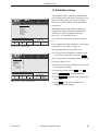
a
Shock
(198 J)
b
c
d
17.07.1999 09:30:26 HR:161 bpm
Pads
Patient………………..…. :
Date of birth…...…….…. :
User.......……………..…. :
Comments....……….….. :
Defib Mode……………... :
Selected Energy…..…....:
Delivered Energy............ :
No of Shocks………..…. :
semiautom./button
200 J
198 J
1
HR Alarm Limits... ……...: 40 :160 bpm
ETC Alarm Limits…...…. : 20 : --- mmHg
HELLIGE
25 mm/s 1 cm/mV 50Hz 35Hz
f
Figure 5-5.
34
g
e
Example of a recording initiated by a defibrillation shock
a reason for recording, delivered energy
b date, time
c heart rate
d intervention report
e user text
f speed, gain, filter(s)
g shock delivery, 5 seconds blanked
Marquette Responder® 3000
227 490 02-C
Semiautomatic Defibrillation
ECG Acquisition via Separate ECG Electrodes
red
yellow
R
L
white
C
Use only silver/silver-chloride electrodes to
acquire the ECG signal. These electrodes prevent
polarization voltages which may be caused by the
defibrillation shock, resulting in an ECG trace on
the monitor screen or recording that simulates
cardiac arrest. The ECG can be picked up with 5
or with 10 electrodes (for ECG measurement,
however, 10 ECG electrodes are required (chapter
8)).
•
•
black
N
Figure 5-6.
ECG electrode placement
161
•
•
bpm
15.07.1999
09:05:00
Energy
available
Check patient
SpO2
etCO2
).
QRSPulse
Tone
OFF
ECG
.
− Press F1 I...III, aV...V, Paddle again.
A menu for selection of the ECG lead appears.
200 J
Next
Menu
− Using F1, select the lead to be displayed in
channel 1, with F2 select the lead for channel 2, and with F3 select the lead for channel 3 (with each key press the device advances to the next lead).
ECG display (acquisition via
separate ECG electrodes)
− Press F5 Previous Menu and change the signal
size with F2 1 cm/mV .
Note
The main menu will automatically reappear, when
− Press F5 Next Menu for about 2 seconds to
return to the main menu.
no button is activated for a period of 30 seconds.
•
227 490 02-C
Turn on the device (energy selector to
− Press F1
III
Figure 5-7.
Via the patient cable, connect the electrodes to
the defibrillator.
Follow these steps to change the displayed leads or
the signal size:
II
ECG
Ensure that only those leadwires are connected
to the patient cable that are actually required.
On the monitor screen you will now see the 3 ECG
leads selected in the setup menu (factory defaults:
leads I, II, III, Figure 5-7). The analysis algorithm
always uses ECG lead II. If lead II is not available,
the first suitable ECG lead shown will be selected.
I
160 / 40
ECG
green
F
Apply the electrodes as shown in Figure 5-6.
Defibrillate the patient as described on page 32.
Marquette Responder® 3000
35
Pacemaker
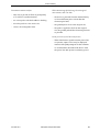
6 Pacemaker
Some Basic Facts
Application and Functional Description
The transcutaneous pacemaker of the Marquette
Responder® 3000 is used for external (transchest)
cardiac stimulation in emergencies. It is applied
temporarily in cases of acute arrhythmia, such as
cardiac arrest or Stokes-Adams attacks. Specific
forms of bradycardia and tachycardia can also be
treated with the pacemaker.
The pacemaker offers two modes of operation:
demand and fixed-rate pacing ("Fix").
The pacer pulses are delivered via the adhesive
defibrillation electrodes (pace pads). Electrodes
919 202 94 (for adults) and 919 202 09 (for
children) can be used.
Separate ECG electrodes must be applied for
acquisition of the ECG signal.
Turning the pacemaker ON:
1. Apply ECG electrodes to patient.
2. Connect ECG electrodes to the device.
3. Turn on the Marquette Responder® 3000
(energy selector to
).
4. Check ECG and vital signs.
5. Attach pace pads to patient.
6. Connect pace pads to the Marquette
Responder® 3000.
7. Turn the pacemaker ON (button
On
Off
).
Turning the pacemaker OFF:
1. Turn the pacemaker OFF (button
On
Off
).
2. Disconnect pace pads from the Marquette
Responder® 3000.
3. Remove pace pads from patient.
4. If monitoring of the patient is no longer
required, turn off the Marquette Responder®
3000 (energy selector to OFF).
5. Remove ECG electrodes from patient.
Caution
Warning
Success of the Intervention — Verify the success
Shock Hazard — Due to their functional require-
of pacemaker stimulation by measuring the pulse
ments, pacemakers operate with high voltages and
rate, not the heart rate.
are therefore equipped with specially protected
outputs. Nevertheless, it is important not to touch
Warning
live contacts with conductive metal objects, such
as tweezers, as long as the pacemaker is operating.
Pausing the Pacemaker — Pushing the
Currents exceeding 10 µA may induce ventricular
button automatically pauses the pacer output and
fibrillation, if they flow through the heart.
suspends delivery of pacer pulses. Pressing the
Observe the following sequence of operating steps
when turning the pacemaker on and off:
36
Start
Pause
Analyse
button will terminate the pacer pause and
resumes pacing with the previous settings.
Marquette Responder® 3000
227 490 02-C
Pacemaker
Guidelines for the Application of External Pacemakers
All electrical devices that deliver energy to
patients in any form or have an electrically
conductive connection to the patient present a
potential hazard.
The user is responsible for the safe application of
the devices. Observance of the instructions given
in the user manual and of the guidelines below is
therefore of utmost importance:
•
•
•
•
•
•
•
•
Pacemakers must only be used under the
supervision of qualified and authorized staff.
The prerequisite for safe application is the use
of intact devices in rooms that meet the applicable requirements. Expert knowledge, good
organization and special care in selecting the
technical installation as well as regular maintenance are required to ensure such operating
conditions.
•
Check the defibrillator performance before
using the pacemaker on a patient.
The pulse current output of the pacemaker is
ungrounded. This ensures that the pacer current
only flows between the pacemaker electrodes.
If the patient needs to be defibrillated while the
pacemaker is on, the pacemaker pauses when
the defibrillator begins charging, and the delivery of pacer pulses is suspended. After delivery
of the defibrillation shock, you can resume the
pacemaker operation with the previous settings
Start
.
by pressing Pause
Use only the electrodes and cables listed in
chapter 20 "Order Information".
Medical electrical devices such as the
Marquette Responder® 3000 must only be
handled by persons who are trained in the use
of such equipment and are capable of applying
it properly.
Before using the device, the operator is obliged
to verify that it is in correct working order and
operating condition.
It is assumed that the patient's ECG is being
monitored to be able to assess the effect of
pacing. Furthermore, at least one of the persons
present must be trained in the use of the defibrillator.
227 490 02-C
Marquette Responder® 3000
37
Pacemaker
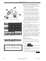
Demand Pacing
Warning
Shock Hazard — During pacing set the energy
selector to
to prevent that a defibrillation
Caution: The pacer pulses are delivered via the
adhesive defibrillation electrodes which must be
applied as described in chapter 4.
Separate electrodes must be applied for acquisition
of the ECG signal (chapter 7).
pulse is triggered inadvertently.
The pacemaker can be enabled only when adhesive
electrodes are connected.
In demand mode, the pacemaker does not deliver
pacing pulses as long as the patient's intrinsic heart
rate exceeds the set pacing rate. When the heart
rate drops below the pacing rate, the pacemaker
starts emitting stimulation pulses. This can only be
ensured by continued electronic monitoring of the
ECG. The necessary synchronization pulses are
automatically sent to the pacemaker.
25
Pacer
24
On
Off
Dem
Fix
22
Start
Pause
21
P/min
+
—
20
mA
19
Figure 6-1.
+
—
Pacemaker operating controls
19 Button to change the pacer current output
20 Button to change the pacer rate
21 Button to pause the pacer function (settings remain stored)
22 Button to toggle between demand
and fixed-rate pacing
24 Button to enable and disable the
pacemaker
25 Indicator is illuminated when the
pacemaker is on and goes off briefly
with each delivered pacer pulse
The demand mode is the recommended pacing
mode when the patient is at risk of developing
bradycardia or even cardiac arrest as a result of a
critical event. As the pacemaker function is
controlled by the patient's ECG, the harmful
competition between intrinsic and external
stimulation which could induce ventricular
fibrillation is excluded.
•
•
Check that the ECG electrodes and the pace
pads are correctly applied and connected to the
device.
Press
On
Off
(24, Figure 6-1) to turn on the
pacemaker.
The device defaults to the Demand mode and
selects a pacer rate of 60 P/min (configurable)
(Figure 6-2).
Caution
Interrupted Arrhythmia Monitoring — Arrhythmia monitoring is disabled while the pacemaker is
operating.
38
Marquette Responder® 3000
227 490 02-C
Pacemaker
•
62
ECG
+
—
,
e.g. 20 mA (19, Figure 6-1).
II
160 / 40
mA
Select a low pacer current output with
bpm
I
•
Select the required pacer rate with
•
Now increase the pacer current output slowly
P/min
+
—
.
mA
with
60
0
—
until the heart reliably responds to
the stimulation.
III
Pacer Dem.
+
P/min
mA
ECG
15.07.1998
SpO2
etCO2
Figure 6-2.
•
09:05:00
QRSPulse
Tone
OFF
manual
Next
Menu
Increase the pacer current output another 5 mA
to ensure continued stimulation.
•
Verify the stimulation by watching the ECG on
the display.
Pacer window
•
You can press
press
Start
Pause
Start
Pause
to pause the stimulation and
again to resume pacing with the same
settings.
•
After therapy, turn off the pacemaker before
removing the pace pads carefully.
(To turn off the pacemaker press the
On
Off
button
for at least 2 seconds (this is to prevent that the
pacemaker is turned off inadvertently.) For this
reason the Marquette Responder® 3000 cannot
be turned off while the pacemaker is on.
227 490 02-C
Marquette Responder® 3000
39
Pacemaker
Fixed-Rate Pacing
Note
-
The default pacer rate can be configured.
-
If a defibrillation shock is triggered during
pacing, the pacemaker pauses automatically.
-
End the therapy as described under "Demand
Pacing" above.
Caution
Interrupted Arrhythmia Monitoring — Arrhythmia monitoring is disabled while the pacemaker is
operating.
Caution: The pacer pulses are delivered via the
adhesive defibrillation electrodes which must be
applied as described in chapter 4.
Separate electrodes must be applied for acquisition
of the ECG signal (chapter 7).
The pacemaker can be enabled only when adhesive
electrodes are connected.
In fixed-rate mode, the device delivers pacing pulses
at the selected rate and current. The selected rate
remains constant and is not affected by intrinsic
actions of the patient's heart. This is the preferred
mode for cases of cardiac arrest.
•
•
Check that the ECG electrodes and the pace
pads are correctly applied and connected to the
device.
Press
On
Off
(24, Figure 6-1) to turn on the
pacemaker. The device defaults to the Demand
mode and selects a pacer rate of 60 P/min
(configurable).
•
Press the
Dem
Fix
button for 3 seconds to activate
the fixed-rate pacing mode (in the pacemaker
window on the screen, you will see "Fix"
instead of "Dem" (Figure 6-2).
•
•
•
•
•
40
Indicator 25 (Figure 6-1) goes off briefly with
each delivered pacing pulse.
P/min
Select the required pacer rate with
+
—
.
Now increase the pacer current output slowly
with + — until the heart reliably responds to
the stimulation.
mA
Verify the stimulation by watching the ECG on
the display.
Increase the pacer current output another 5 mA
to ensure continued stimulation.
Marquette Responder® 3000
227 490 02-C
Displaying and Monitoring the ECG
7 Displaying and Monitoring the
ECG
red
yellow
Displaying the ECG
R
L
white
C
black
N
Figure 7-1.
green
F
Signal acquisition with 5 electrodes
red
yellow
R
•
C2
C3
C4 C5 C6
C8
N
green
F
C1 C2 C3C4
C5
Chest electrode placement
R
1
2
34 5 6
L
F
C
C1
C2
C3
C4
N
F
Connect one (5 electrodes) or both leadwire
blocks to the patient cable (Figure 7-3).
Set the energy selector to
.
After the test screen, the standard screen display
will appear (Figure 7-4), showing leads I, II and III
(factory defaults).
Note
− ECG lead II is used for analysis and for calculation of the heart rate. If lead II is not
available, the first suitable ECG lead displayed
will be selected.
N
L
R
If you are using only 5 electrodes, apply them
as shown in Figure 7-1. When working with 10
electrodes, additionally apply all chest electrodes as shown in Figure 7-2.
Ensure that all leadwires are always connected.
Otherwise the connector of the leadwire may come
in contact with conductive parts and cancel the
protection provided by the isolated patient input.
•
C7
C6
Figure 7-2.
•
L
C1
black
For a quick diagnosis of the ECG, you can use the
defibrillation electrodes (paddles) to acquire the
ECG.
For in-depth examinations and heart rate monitoring, the ECG signal should be acquired via
separate ECG electrodes. Five or 10 ECG
electrodes can be applied to the patient. Ten
electrodes are required for the 12SL measurement
and interpretation program. Use silver/silver
chloride electrodes, if possible. Otherwise the
polarization voltages caused by the defibrillation
shock could simulate cardiac arrest.
C5
C6
− The 3-lead patient cable cannot be used with
this defibrillator.
Figure 7-3.
227 490 02-C
Connecting the leadwires to the
patient cable
Marquette Responder® 3000
41
Displaying and Monitoring the ECG
62
160 / 40
ECG
The HR window is green, indicating that no
electrode problem was detected and the heart rate is
within the alarm limits. If an electrode problem
exists, the color changes from green to blue (in
addition, an audio signal sounds after 30 seconds configurable). If the HR violates one of the alarm
limits, the color changes from green to red.
I
bpm
II
III
The default defibrillator settings are:
15.07.1999
ECG
Figure 7-4.
SpO2
etCO2
09:05:00
QRSPulse
Tone
OFF
semiautom.
Next
Menu
Standard screen display with ECG
− leads I, II, III (configurable)
− AC line filter enabled, muscle filter enabled
(configurable)
− gain 1 cm/mV (configurable)
− the audio alarm for heart rate and CO2
monitoring is disabled
Note
The main menu will automatically reappear, when
no button is activated for a period of 30 seconds.
− arrhythmia monitoring is enabled (do not rely
on this alarm alone because it will only be
activated in the event of shockable arrhythmias;
also monitor the patient by means of the HR
alarm limits).
These settings can be changed permanently from
the setup menu (chapter 13 "Defibrillator Setup")
or temporarily.
For monitoring of the heart rate, please observe the
information in the following section "Heart Rate
Monitoring".
Assigning Channel Waveforms
•
•
•
Press F1
Press F1
ECG
.
I...III, aV...V, Paddle
again.
Using F1, select the lead to be displayed in
channel 1, with F2 select the lead for channel 2,
and with F3 select the lead for channel 3 (with
each key press the device advances to the next
lead).
Gain Selection
•
•
42
Press F1
ECG
.
Change the signal size with F2
Marquette Responder® 3000
1 cm/mV
.
227 490 02-C
Displaying and Monitoring the ECG
Activating and Deactivating Filters
Activating muscle and AC line filters makes the
displayed ECG insensitive to AC interference and
muscle tremor. However, the filters alter the ECG
signal, and a filtered signal is not suitable for
diagnosis (displayed or printed ECG). The heart
rate is always derived from the raw ECG signal.
•
•
•
Press F5
Next Menu
.
Using F1 Filter , enable or disable the muscle
filter, as appropriate.
The AC line filter is enabled and disabled from
the setup menu.
Note
Active filters will alter the ECG signal. Switch off
the filters to obtain a diagnostic ECG.
Enabling/Disabling the QRS Beep
The QRS beep can be enabled (high, middle, low
volume) and disabled with F3 QRSPulse Beep .
227 490 02-C
Marquette Responder® 3000
43
Displaying and Monitoring the ECG
Monitoring Heart Rate
The default heart limits are 40 and 160 bpm and
Warning
the audio alarm is disabled (factory default
No Asystole Alarm — The defibrillator gives
asystole alarm only when the heart rate falls
below the low HR limit. Therefore, do not disable the low HR limit.
-
Incorrect HR / No HR Alarm — In the presence of arrhythmias and morphological
changes of the ECG, the device may not be
able to calculate the correct heart rate. Beats
may be counted twice or may be ignored.
-
settings, bell symbol in button F4 is crossed out
). The audio alarm can be enabled permanently
from the setup menu or temporarily with F4
(symbol
appears).
The defibrillator reports an alarm condition if the
HR exceeds one of the alarm limits for more than
10 seconds:
− the HR window and the QRS indicator change
from green to red,
Note
The defibrillator can be set up to automatically activate the alarm tone on power up. The
default alarm limits can also be adjusted in
the setup menu.
-
Furthermore the defibrillator can be set up for
continuous ECG analysis. If the algorithm
identifies shockable arrhythmias, the defibrillator will display the message "Check Patient"
(manual defibrillator) or "Press Analyse"
(semiautomatic defibrillator). When the audio
alarms are active, the device will also emit an
audible signal.
During patient transport the device may fail to
identify these arrhythmias due to motion artifact.
-
91
160 / 40
ECG
I
bpm
15.07.1998
09:05:00
semiautom.
Figure 7-5.
44
− the alarm is annotated in the full disclosure
ECG.
When the parameter reading returns to the normal
range, the window and the QRS indicator change
back to green and the audio alarm stops.
You can also silence the alarm tone with F4 . If
the alarm cause persists, the alarm condition is
reported again after 120 s (a count-down timer in
the button indicates the remaining time in
seconds).
To permanently disable the audio alarm, press the
button longer than 2 seconds. Then the symbol
reappears.
•
•
III
High
− the recorder starts (configurable),
The alarm limits can be modified permanently
from the setup menu or temporarily as described
below:
II
ECG
− the audio alarm sounds (configurable),
Alarm
Low
ECG
Alarm
Previous
Menu
Press F1
Press F3
ECG
.
Alarm Limits
.
The display shown in Figure 7-5 will appear.
•
Change the high limit with F1/F2 and the low
limit with F3/F4.
Buttons for modification of the HR
alarm limits
Marquette Responder® 3000
227 490 02-C
Displaying and Monitoring the ECG
Monitoring Arrhythmia
Monitoring Pacemaker Patients
The device allows you to continuously monitor the
ECG for arrhythmias (see Appendix "The
Arrhythmia Detection Program").
When monitoring the heart rate of pacemaker
patients, only the patient's QRS complexes must be
counted and pacer pulses must be rejected. For this
purpose, the Marquette Responder® 3000 has an
electronic pacer pulse suppression algorithm
which rejects the pacer pulses so they are not
counted as QRS complexes. Depending on the
pacemaker model used and on the position of the
electrodes, the compensation pulse following
every pacer pulse may be considered as a QRS
complex. Every pacemaker must provide an
oppositely charged current (reverse current) after
delivering a pacing pulse. In this situation and
when the pacer pulse is ineffective, the displayed
heart rate may be misinterpreted, and the device
will not give alarm in the presence of bradycardia
or asystole.
The program is enabled and disabled from the
setup menu (see chapter 13, section "Device –
Analysis").
When the program is active, you will see the
message "VF/VT" in the ECG parameter window
(Figure 7-6).
When the analysis algorithm detects a shockable
arrhythmia, the message "Check Patient" (manual
defibrillator) or "Press Analyse" (semiautomatic
defibrillator) is displayed, and the device will also
give VF alarm. When the audible alarm is active
you will also hear an alarm tone.
Enabling the pacemaker will automatically
interrupt the arrhythmia monitoring program.
Due to motion artifact the device may not be able
to detect these arrhythmias during patient
transport.
Note
Do not rely on this alarm alone because it will
only be activated in the event of shockable arrhythmias; also monitor the patient by means of
Always monitor pacemaker patients by means of
separate ECG electrodes and not via the defibrillation electrodes.
As an additional precaution, monitor pacemaker
patients by means of pulse oximetry.
It depends on the pacer pulse parameters, whether
or not the compensation pulse is counted as a QRS
complex (see chapter 19 "Technical Specifications").
the HR alarm limits.
For pacemaker patients, the ECG signal size
should be greater than 1 mV.
VF / VT
62
ECG
I
160 40
Warning
bpm
No HR Alarm — If several adverse conditions
II
exist at once during monitoring of pacemaker
patients, the possibility that pacer pulses are interpreted (and counted) as QRS complexes should be
III
considered. Therefore, pacemaker patients should
15.07.1999
ECG
SpO2
etCO2
Figure 7-6.
227 490 02-C
always be watched closely.
09:05:00
QRSPulse
Tone
OFF
semiautom.
Next
Menu
Arrhythmia monitoring enabled
Marquette Responder® 3000
45
TM
12-Lead ECG Analysis Program (12SL )
8 12-Lead ECG Analysis Program (12SL TM)
Introduction
Overview
The first human electrocardiogram was taken over
a hundred years ago, and computerized electrocardiography has been in existence since the late
1950s.
The pioneers of this technology had motivations
which could mimic human activity to the basic
requirement of efficiently recording artifact free
tracings.
Computerization has resulted in two practical
advantages for the overreading physician. First, the
computer can serve as an additional expert
opinion. Second, cardiologists have found that it is
possible for them to overread computer analyzed
tracings in half the time required for conventional,
non-analyzed ECGs.
A program's accuracy is directly dependent upon
the quality of the signal it acquires. In 1979,
Marquette Hellige introduced an electrocardiograph that simultaneously acquired all of the leads
from the 12-lead electrocardiogram. Prior to this
time, all commercially available electrocardiographs could only acquire 3 leads at a time.
Simultaneous recording was adopted so that the
computer could use all signals from all 12 leads to
properly detect and classify each QRS complex.
The computer, therefore, is not only used to
efficiently record, store, transmit, and present the
ECG; but it is also used to assist the physician in
overreading an ECG.
It should be made clear that a computerized
analysis is not a substitute for human interpretation. There are two reasons for this. First,
statements of accuracy need to be viewed from a
statistical perspective. Although accuracy levels
may be high, outliers can and will exist. Second, a
computer does not have the ability to include the
entire clinical picture of the patient. A person with
organic heart disease can exhibit an ECG within
normal limits. Conversely, a normal individual can
have an abnormal appearing ECG. The ECG,
therefore, must always be reviewed in light of the
surrounding clinical circumstances.
46
Marquette Responder® 3000
227 490 02-C
12-Lead ECG Analysis Program (12SL
TM
)
Median Beat, Signal Averaging
Measurements, Onsets and Offsets
Computer measurement for features within the
QRS complex are very susceptible to artifact. To
remove artifact, filtering may be used. Beyond
filtering, there is another method able to eliminate
noise from the QRS complex: signal averaging.
Instead of analyzing a single QRS complex, the 12
SL program generates a median complex. In other
words, all QRS complexes of the same shape are
aligned in time. Next, the algorithm generates a
representative QRS complex from the median
voltages that are found at each successive sample
time. This is more complicated than creating an
average. The method results in a cleaner signal
since it is able to disregard outliers.
All ECG computer programs are composed of two
parts: one which measures the waveforms and one
which does the analysis based upon those
measurements. The main task of computerized
measurement determines the location of major
reference points (onsets and offsets for P, QRS,
and T waves).
Consistent with the signal processing portion of
the program, the major wave onsets and offsets are
delineated by an analysis of the slopes in all 12
simultaneous leads. That is, QRS duration is
measured from the earliest onset in any lead to the
latest deflection in any lead. Similarly, the QT
interval is measured from the earliest detection of
depolarization in any lead to the latest detection of
repolarization in any lead.
After the onsets and offsets for P, QRS, and T
complexes have been demarcated, the waves
within each complex are then measured according
to published standards. These amplitudes and
durations result in a measurement matrix containing more than 1600 values. Measurements are then
passed onto the criteria portion of the program so
that it can generate an interpretation.
Comparisons of all averaging against all nonaveraging programs yields a 70% higher detection
instability for the non-averaging programs and
worse performance in most tested measurements.
Literature
"Marquette Hellige 12SLTM ECG Analysis
Program",
PN MO 1417 DE 0, English
227 490 02-C
Marquette Responder® 3000
47
12-Lead ECG Analysis Program (12SL
TM
)
12SL Measurement
62
160 / 40
ECG
I
bpm
15.07.1998
09:05:00
semiautom.
Start
Print
Figure 8-1.
62
160 / 40
ECG
Recall
Previous
Menu
12SL analysis menu
For measurement and interpretation 12 seconds of
ECG data are saved. After the analysis, the
interpretation is presented on the monitor screen.
You can also print the ECG including the
measurement results and the interpretation. The
printed segment, however, is only 3,2 seconds.
If 12SL analysis was already performed with the
defibrillator when you activate the program, the
previous interpretation will appear on the display.
In addition, the full-disclosure ECG of channel 1 is
stored in the ECG memory.
•
•
•
I
bpm
Press F1
ECG
.
Display the 12SL menu with F4
8-1).
Press F1
Start
12SL
(Figure
to start the program.
After acquisition, the ECG data is analyzed and
stored. Afterwards, the interpretation is displayed
on the screen (Figure 8-2).
20.07.1998 14:35:37
NORMAL SINUS RHYTHM
NORMAL ECG
Press F2 Print to print the ECG, including
measurement results and interpretation.
20.07.1998
14:35:37
semiautom.
Recall
Figure 8-2.
48
Recall
Recall
Previous
Menu
Press F4 Recall to recall the 3 most recent 12SL
records. The corresponding acquisition time is
shown in the softkey.
12SL interpretation
Marquette Responder® 3000
227 490 02-C
Pulse Oximetry
9 Pulse Oximetry (SpO2)
Some Basic Facts
89
160 / 40
ECG
97
SpO2
SpO2 measurement is used to determine the
percentage of functional hemoglobin saturated
with oxygen in the patient's arterial blood. Alarm
limits can be set for monitoring of the SpO2 value.
The plethysmogram waveform can be displayed on
the screen (Figure 9-1).
I
bpm
--90
%
SpO2
III
15.07.1999
09:05:00
semiautom.
ECG
Figure 9-1.
SpO2
etCO2
QRSPulse
Tone
OFF
Next
Menu
SpO2 value and plethysmogram
Warning
False Parameter Readings — Pulse oximetry is
not suitable for oxygen monitoring of fetuses
(ante-partum or sub-partu). Also this method is
not suitable for patients with carbon monoxide
The device measures arterial oxygen saturation by
a method called pulse oximetry. This method is
based on the measurement of the different
absorption spectra of reduced hemoglobin and
oxyhemoglobin.
Therefore the probes consist of a light source (two
LEDs in most cases) and a photodetector on the
opposite side which collects the incident light.
After interaction with the blood and tissue, the red
and infrared light (range between 660 nm and 940
nm) from the LEDs hits the photodetector which
converts it into an electrical signal. The pulsatile
component of the signal is used to build the
plethysmogram.
poisoning.
Elevated levels of carboxyhemoglobin (CO-Hb)
and methemoglobin (Met-Hb) may affect the
measured values. Also dyes injected in the blood
stream (such as Cardiogreen) may impair meas-
Literature
WUKITSCH, M.W.; PETTERSON, M.T.; TOBLER,
D.R.;POLOGE, J.A.: Pulse Oximetry: Analysis of
urement accuracy.
Theory, Technology, and Practice, J. Clin. Monit. 4:
290–301 (1988)
Warning
No Alarm — Under certain conditions the device
may not be able to identify a signal disturbance
when monitoring the patient. In this situation
artifacts are capable of simulating a plausible
CECIL, W.T.; THORPE, K.J.; FIBUCH E.E.; TUOHY, G.F.:
A Clinical Evaluation of the Accuracy of the Nellcor N100 and Ohmeda 3700 Pulse Oximeters, J. Clin. Monit.
4: 31–36 (1988)
parameter reading, so that the monitor fails to
sound an alarm. In order to ensure reliable patient
monitoring the proper application of the probe
and the signal quality must be checked at regular
intervals.
227 490 02-C
Marquette Responder® 3000
49
Pulse Oximetry
C-Lock ECG Synchronization
Application Tips
The C-Lock ECG synchronization feature enables
the device to use an ECG signal as a reference
point for identifying the pulse and synchronizing
saturation measurements. This enhances the
measurement accuracy when the patient's
perfusion is poor and in the presence of patient
movement.
When an ECG signal is present during SpO2
measurement, the device receives two separate
signals that reflect cardiac activity; an optical/electrical signal from the SpO2 probe and the
ECG signal. The time that elapses between the
ECG R-wave and the optical pulse detected at the
probe site depends on the heart rate and on the
location of the probe. However, for a given patient
the length of the delay is relatively stable, and the
device uses that time relationship to identify good
pulses and reject non-synchronized artifacts.
General Tips
− Use only the probes listed in chapter 20 "Order
Information". Apply the probes as described in
their instructions for use. Carefully observe all
information and cautions given in these instructions.
− Take care that the probe does not exert too
much pressure when applied to avoid erroneous
readings and blistering. Inadequate oxygen
supply to the skin, not heat, causes blisters.
− Change the probe site at least every 24 hours to
allow the skin to breathe.
− Be careful to ensure continued circulation at
the probe site.
− Incident light may cause inaccurate readings.
Cover the measuring site with a cloth, if necessary.
− It may not be possible to measure SpO2 values,
if cardiac output is determined at the same time
by means of the dye dilution technique.
− It may not be possible to measure SpO2 values
or the pulse rate, if the circulation is impaired
(e.g. by a blood-pressure cuff or by an extremely high vascular resistance).
− Remove nail varnish and artificial finger nails
before applying the probe. Both may lead to
inaccurate readings.
− Do not apply the finger probe to the same arm
as the blood-pressure cuff.
50
Marquette Responder® 3000
227 490 02-C
Pulse Oximetry
To minimize motion artifact
− take care to provide an ECG of good quality
(C-Lock ECG synchronization),
− use a new probe with fresh adhesive backing,
− move the probe to a less active site,
− select a slow integration time.
When monitoring SpO2 during electrosurgical
intervention, take care that
− the device is powered from the internal battery
or from a different power circuit than the
electrosurgical unit,
− the ground pad is close to the surgical site,
− the probe is applied as far from the surgical
site, the ground pad and the electrosurgical unit
as possible.
In the presence of AC line interference
− When interference signals from the power line
are present, square waves may be displayed
instead of the plethysmogram. In this situation
we recommend to disconnect the device from
the power line and operate it on battery power.
227 490 02-C
Marquette Responder® 3000
51
Pulse Oximetry
Measuring and Monitoring Oxygen
Saturation
89
160 / 40
ECG
97
SpO2
•
I
bpm
The SpO2 measurement begins as soon as the
sensor is connected. During the short self-test, the
parameter window is blue. As soon as the probe
supplies a valid signal, the color changes to green
(Figure 9-2).
--90
%
II
III
15.07.1999
09:05:00
semiautom.
ECG
Figure 9-2.
SpO2
etCO2
Apply the probe as described in the user
instructions supplied with the probe and connect it to the defibrillator (blue connector).
QRSPulse
Tone
OFF
Next
Menu
SpO2 parameter window
At the factory, only a low limit of 90% is adjusted,
no high limit. When the parameter reading drops
below this value, the defibrillator sounds an alarm
and the window changes from green to red.
Enabling/Disabling C-Lock ECG Synchronization
C-LOCK
OFF
Figure 9-3.
Integ.
Time
8s
QRSPulse
Tone
OFF
HR
Source
ECG
Previous
Menu
SpO2 menu
With the factory default settings unchanged, the CLock ECG synchronization is disabled when the
device is first turned on. If the ECG signal is
acquired, enable the feature.
•
•
Note
Disable the C-Lock ECG synchronization feature
when monitoring pacemaker patients.
•
Press F2
SpO2 etCO2
.
Press F3 SpO2 to display the SpO2 menu
(Figure 9-3) (displays only when SpO2 probe is
connected).
Press F1 C-LOCK to enable the C-Lock feature
(or press the key again to disable it).
Selecting the Integration Time
Warning
Delayed Alarm — When monitoring the pulse rate
derived from the SpO2 signal instead of the heart
rate, select an integration time of 4 or 8 seconds;
do not select 12 seconds because of the slower
display update.
The integration time is the time over which the
measured values are averaged. You can select an
integration time of 4, 8 or 12 seconds. The default
setting is 8 seconds. The integration time of 12
seconds should only be selected in exceptional
cases.
•
•
52
Display the SpO2 menu as described above
(Figure 9-3).
Select the integration time with F2
Marquette Responder® 3000
Integ. Time
.
227 490 02-C
Pulse Oximetry
Selecting the HR Source
The device can be set up to derive the heart rate
from the SpO2 signal. The heart rate source is
selected with F4 in the SpO2 menu (Figure 9-3).
Adjusting Alarm Limits
Alarm
High
Low
SpO2
Alarm
SpO2
Figure 9-4.
Previous
Menu
Alarm limits menu
•
•
Note
SpO2 alarms are similar to HR alarms. Please
refer to chapter 7 "Displaying and Monitoring the
ECG".
↓
ECG
QRSPulse
Tone
OFF
SpO2
etCO2
Figure 9-5.
Figure 9-6.
Memory
Display
Figure 9-7.
89
160 / 40
ECG
97
SpO2
ECG
Vit. Sign
Vit. Sign
Press F2 SpO2 Alarm Limits to display the alarm
limits menu (Figure 9-4).
Change the high limit with F1, F2 and the low
limit with F3, F4.
To deactivate the SpO2 measurement, remove
the probe connector and press F2 SpO2 etCO2 .
The plethysmogram can be displayed in channel 2
or 3 with a sweep speed of 25 mm/s.
Previous
Menu
•
•
•
↓
ECG
.
Previous
Menu
Main menu, page 2
2 Channel 3
Channel 1 Channel
ECG
•
SpO2 etCO2
Displaying the Plethysmogram
↓
Filter
ON
•
Press F2
Next
Menu
Main menu
Assign
Channel
Waveform
The alarm limits can be modified permanently
from the setup menu or temporarily as described
below:
Menu to assign waveforms to
channels
•
Press F5
Next Menu
Press F2
Assign Channel Waveform
(Figure 9-5).
(Figure 9-6).
Press F2 (Figure 9-7) repeatedly until "SpO2" is
displayed (Figure 9-8).
When the SpO2 measurement is disabled, a
sawtooth signal is displayed which can be
replaced with an ECG lead.
I
bpm
--90
%
SpO2
III
15.07.1999
09:05:00
semiautom.
ECG
Figure 9-8.
227 490 02-C
SpO2
etCO2
QRSPulse
Tone
OFF
Next
Menu
Plethysmogram in channel 2
Marquette Responder® 3000
53
Capnometry (etCO2)
10 Capnometry (etCO2)
Some Basic Facts
c
CO 2 ADAPTER
a
!
OPER/ALARM
b
Figure 10-1. CO2 sensor and airway adapter
a airway adapter
b sensor
c adapter cable
Infrared
light source
Airway
adapter
No-fog
membrane
The etCO2 sensor uses the infrared spectroscopy
method. The sensor consists of the sensor itself b
(including the IR source and the photodetector) and
the airway adapter a which is attached to the sensor.
The entire sensor is placed in the patient's airway
(expired air) between the respirator and the tube. The
airway adapter is for single use only. It must not be
reused (Figure 10-1). The etCO2 value is given in
mmHg and can be monitored. A capnogram
waveform can be displayed on the screen.
Principle of Operation
The method of infrared spectroscopy is based on the
fact that the CO2 gas in the patient's expired air
absorbs infrared light at specific wavelengths. The
absorbed amount of light is in proportion with the
amount of CO2 in the respired air. A "No-fogmembrane" ensures that no condensation collects on
the sensor (Figure 10-2). The method used is a
semi-quantitative measuring method and it is
assumed that the inspired air is free of CO2.
etCO2 Monitoring Literature
Falk J L, Rackow E C, Weil M H (1988) End-tidal carbon
dioxide concentration during cardiopulmonary resuscitation. New Engl J Med 318: 607-611
MacLeod B A, Heller M B, Gerard J et al. (1991) Verification
Filter
(4.3 µm)
of endotracheal tube placement with colorimetric end-tidal CO2
detection. Ann Emerg Med 20: 267-270
Sanders A B, Kern K B, Otto C W (1998) End-tidal carbon
Detector
dioxide monitoring during CPR: A prognostic indicator for
survival. JAMA 262: 1347-1351
Figure 10-2. Principle of operation
White R D, Asplin B R (1994) Out-of-hospital quantitative
monitoring of end-tidal carbon dioxide pressure during
CPR. Ann Emerg Med 23: 25-29
Bhavani-Shankar K; Mosley H; Kumar Y Y (1992)
Capnometry and anaesthesia (Review Article). Can. J.
Anaesth. 39: 617-632
54
Marquette Responder® 3000
227 490 02-C
Capnometry (etCO2)
Safety Information
Warning
Observe the following information to prevent
-
The sensor may give lower readings when
used in a low pressure environment (do not
use in airplane).
-
Do not allow condensation to develop in the
sensor, condensation can attenuate the signal,
resulting in degraded performance.
-
The sensor may give erroneous readings when
exposed to rapid temperature changes.
-
The readings may be inaccurate when CO2 is
present in the airway adapter during inspiration. The displayed etCO2 values are based on
the assumption that the inspired air is free of
CO2.
The readings obtained during mouth-tomouth resuscitation may therefore be inaccurate. The same is true if Jackson-Rees and
Mapleson-D ventilators are used.
-
The readings may be inaccurate in patients
with high or irregular respiration rate (indicator in sensor goes briefly off).
-
The measurement accuracy depends on the
altitude of the measurement site. It decreases
with increasing altitude (Figure 10-6).
erroneous CO2 measurements. Inappropriate
therapeutic measures based on erroneous readings
may cause severe damage or the patient's death.
-
etCO2 measurement is not suitable for patients
under 3 years of age or patients weighing less
than 10 kg.
-
The sensor may give inaccurate readings
when used on patients with a respiration rate
greater than or equal to 60 breaths per minute.
-
etCO2 measurement is not suitable for quantitative measurement during intraoperative
anesthesia or in the ICU environment.
-
etCO2 readings should be considered as additional parameters in the assessment of a patient's condition. They should always be seen
in the context of other clinical signs and
symptoms.
-
Do not use the sensor on patients with small
tidal volumes because the dead space volume
of the airway adapter is about 5 cc. This could
affect the ventilation. If the tidal volume is too
low, the sensor may not be able to detect the
patient's inspiration and expiration.
-
Do not touch or wipe the window of the airway
adapter to avoid damage. If the window is
damaged, water droplets may adhere to the
surface which could affect the performance
and accuracy of the sensor.
-
The airway adapter can be continuously used
for about 24 hours under normal operating
conditions. If blood, sputum or phlegm has
entered the airway adapter, discard the airway
adapter and use a new one.
-
Do not measure the etCO2 concentration on a
patient undergoing an MRI examination. This
could cause the sensor to give inaccurate
readings.
-
High concentrations of nitrous oxide (N2O) or
halogenated anesthetic agents can cause the
sensor to give inaccurate readings.
227 490 02-C
Note
In most cases the endtidal CO2 value (etCO2) is
below the arterial CO2 partial pressure (paCO2)
determined by blood-gas analysis (see Literature).
Possible clinical causes are:
- dead-space ventilation, ventilation/perfusion
mismatch
- decreased cardiac output
- alveolar shunts
- incomplete emptying of the alveoli.
Marquette Responder® 3000
55
Capnometry (etCO2)
Measuring and Monitoring etCO2
• Obtain a new airway adapter and check that the
c
windows are intact and clean.
•
a
•
b
•
d
Figure 10-3. Attaching the airway adapter
•
89
160 / 40
ECG
I
37
--20
mmHg
III
15.07.1998
09:05:00
semiautom.
ECG
etCO2
SpO2
Connect the airway adapter to the respirator
system (connector c towards the patient, connector d towards the respirator - Figure 10-3).
Ensure that the sensor is on top and that the
windows of the airway adapter are in a vertical
position. Although the "No-fog-membrane"
prevents moisture condensation on the window,
liquid secretions could soil the window.
Connect the sensor to the defibrillator (yellow
connector, right).
The CO2 measurement begins as soon as the sensor
is connected. During the short self-test, the
parameter window is blue. As soon as the sensor
supplies a valid reading, the color changes to
green. Check that the indicator on the CO2 adapter
cable lights green; if a problem is detected, the
indicator flashes red (apnea or system failure).
bpm
II
etCO2
Attach the airway adapter to the sensor (the
triangles on the airway adapter and on the
sensor must be in alignment - Figure 10-3).
QRSPulse
Tone
OFF
Next
Menu
Figure 10-4. etCO2 reading
At the factory, only a low etCO2 limit of 20 mmHg
is adjusted, no high limit. When the parameter
reading drops below this value, the defibrillator
sounds an alarm and the window changes from
green to red.
Adjusting Alarm Limits
High
etCO2
Alarm
Low
etCO2
Alarm
Previous
Menu
Figure 10-5. Alarm limits menu
The alarm limits can be modified permanently
from the setup menu or temporarily as described
below:
•
•
Note
etCO2 alarms are similar to HR alarms. Please
refer to chapter 7 "Displaying and Monitoring the
•
ECG".
•
56
Press F2
SpO2 etCO2
.
Press F1 etCO2 Alarm Limits to display the alarm
limits menu (Figure 10-5).
Change the high limit with F1, F2 and the low
limit with F3, F4.
To deactivate the etCO2 measurement, remove
the sensor connector and press F2 SpO2 etCO2 .
Marquette Responder® 3000
227 490 02-C
Capnometry (etCO2)
altitude error
0.0%
500
1000
1500
2000
2500
3000
Displaying the Capnogram
3500
4000
4500
5000
-5.0%
The capnogram can be displayed in channel 3 with
a sweep speed of 6.25 mm/s (but it is printed with
a speed of 25 mm/s).
-10.0%
error
-15.0%
-20.0%
•
•
•
-25.0%
-30.0%
-35.0%
-40.0%
altitude (m)
Figure 10-6. Measurement accuracy as a function
of the altitude of the measuring site
•
↓
ECG
QRSPulse
Tone
OFF
SpO2
etCO2
Next
Menu
Figure 10-7. Main menu
↓
Assign
Channel
Waveform
Filter
ON
Memory
Display
ECG
Vit. Sign
Previous
Menu
Figure 10-9. Menu to assign waveforms to
channels
89
160 / 40
ECG
(Figure 10-7).
Press F2
Assign Channel Waveform
(Figure 10-8).
Press F3 (Figure 10-9) repeatedly until "etCO2"
is displayed (Figure 10-10).
When the etCO2 measurement is disabled, a
sawtooth signal is displayed which can be
replaced with an ECG lead.
During the automatic sensor calibration
process, a calibration pulse is superimposed on
the capnogram (a, Figure 10-10).
Cleaning the Sensor
↓
ECG
Vit. Sign
Next Menu
Previous
Menu
Figure 10-8. Main menu, page 2
2 Channel 3
Channel 1 Channel
ECG
•
Press F5
Use a soft cloth moistened with an alcoholic, nonabrasive cleaning agent to wipe the sensor surface
including the IR light source, the photodetector
and the connecting lead carefully clean. Use an
alcoholic, non-abrasive cleaning agent.
I
Caution
bpm
Damage to Sensor — Do not use caustic or abraII
37
etCO2
a
--20
mmHg
etCO2
sive cleaners or hard cleaning utensils.
Do not touch the surface of the IR light source or
of the photodetector with fingers or any hard
object. This could affect the performance of these
15.07.1999
fine optical devices.
09:05:00
semiautom.
ECG
etCO2
SpO2
QRSPulse
Tone
OFF
Next
Menu
Figure 10-10.Capnogram in channel 3
a automatic sensor calibration
Do not autoclave the sensor or sterilize it with
ethylene oxide.
Do not immerse the sensor in liquid.
Warning
Infection Hazard — The airway adapter is for
single use only and must not be reused.
227 490 02-C
Marquette Responder® 3000
57
Memories of the Marquette Responder® 3000
11 Memories of the Marquette
Responder® 3000
Switching off the defibrillator does not automati-
The Marquette Responder® 3000 has 4 different
memories:
cally clear the memories. Therefore, the memories
− an event memory
could contain data from different patients.
We recommend to clear the memories before using
− an ECG memory
the defibrillator on a new patient, or to program
− a trend memory
an event text "New patient" (see section "Event
− a 12SL memory (optional).
Note
Button" in chapter 3 and "Event Texts" in chapter 13).
Changing the date and/or time will clear the
Event Memory
memories.
The event memory stores up to 250 events,
annotated with date, time and parameter readings
(e.g. HR), which document the operating procedures (e.g. device on, off, alarms, defibrillation
-).
shocks, events When the event memory is full, the device updates
the information automatically by saving new
events and deleting old ones. It is also possible to
clear the memories (see below).
Event
↓
ECG
SpO2
etCO2
QRSPulse
Tone
OFF
Next
Menu
•
Figure 11-1. Main menu
↓
Filter
ON
Assign
Channel
Waveform
Memory
Display
Previous
Menu
↓
Trend
Clear
Memory
Print
All
Events
Figure 11-4. Memory menu
58
Next Menu
(Figure 11-
Press F3
Memory
(Figure 11-2).
You will see the memory menu (Figure 11-3).
Playback
Previous
Menu
•
Press F1
Event Text
.
You will see the menu shown in Figure 11-4.
Figure 11-3. Memory menu
Print
Primary
Events
In the main menu, select F5
1).
You will see page 2 of the main menu (Figure 112).
•
Figure 11-2. Main menu, page 2
Event
Text
When printing the contents of the memories you
can choose between a list of the major events
("Primary Events") and of all events ("All
Events").
The primary events include device on, device off,
shock advised, no shock advised, pacer pause,
configuration change, alarm silence and all alarms.
Previous
Menu
•
Press F1 Print Primary Events to print the major
events, or press F2 Print All Events to print all
events.
Marquette Responder® 3000
227 490 02-C
Memories of the Marquette Responder® 3000
ECG Memory
The defibrillator saves the most recent 180
minutes of full disclosure ECG data displayed in
channel 1 and acquired while the defibrillator was
on. When the memory is full, the information is
automatically updated, so that the most recent 180
minutes are always available. It takes about 1
minute before the stored ECG can be played back.
You can either print the full disclosure ECG in 5second segments, or you can search the data for
events that occurred in the last 180 minutes and
then print the corresponding ECG strip.
Events whose ECG strips are older than 180
minutes are still listed in the event memory (if they
are among the most recent 250 events), but the
ECG strip is no longer available. When you
attempt to print this event, the message "No ECG
Data" will be displayed.
Printing the ECG
•
91
I
160 / 40
ECG
bpm
•
II
•
III
21.07.1999
21.07.1998
12:05:15
12:05:15
semiautom.
Select
ECG
Figure 11-5. Playback function
Previous
Menu
Press F5 Next Menu in the main menu to display
page 2 (Figure 11-2).
Display the memory menu with F3
(Figure 11-3).
Display the playback menu with F4
(Figure 11-5).
Memory
Playback
Now you can scroll through the stored ECG in
steps of 5 seconds with F1 and F3. The corresponding time is annotated below the waveform
window (Figure 11-5).
•
Press
Print
Print
to print the displayed segment (press
again to stop the printout).
If you want to find events in the full disclosure
ECG, activate the search function with F4 "Select
Event". You can now move between events with
F1 and F3. Date and time of the event are
displayed below the waveform window.
•
227 490 02-C
Press
Print
Marquette Responder® 3000
to obtain a printout of the event.
59
Memories of the Marquette Responder® 3000
Trend Memory
Note
Power on and off are marked with a vertical line
in the graphic trends.
In the trend memory the device collects the HR,
SpO2 and etCO2 values of the past 4 hours. The
trend data, too, are automatically updated. The
stored data can be printed out in the form of
graphic trends. You can choose between a 1-hour
and a 4-hour trend window.
•
↓
ECG
SpO2
etCO2
QRSPulse
Tone
OFF
Next
Menu
Figure 11-6. Main menu
↓
Filter
ON
Assign
Channel
Waveform
•
•
•
Memory
Display
Previous
Menu
•
Figure 11-7. Main menu, page 2
↓
Event
Text
Trend
Clear
Memory
Playback
Previous
Menu
Figure 11-8. Memory menu
↓
Print
HR
↓
↓
↓
Print
SpO2
Print
etCO2
Trend
4 h
Previous
Menu
Display the memory menu with F3
(Figure 11-8).
Display the trend menu with F2
11-9).
Memory
Trend
(Figure
In the trend menu (Figure 11-9), select the time
window Trend 4 h or Trend 1 h with F4.
The following graphic trends are now available
for printing:
− heart rate with F1 Print HR ,
− SpO2 with F2 Print SpO2 ,
− etCO2 with F3 Print etCO2 .
Clearing the Memories
The memories cannot be cleared individually, all
of them are cleared in one pass .
Figure 11-9. Trend menu
•
a
TREND
Press F5 Next Menu in the main menu to display
page 2 (Figure 11-7).
•
•
01.10.99
Patient..........................:
Date of birth................. :
User..............................:
Comments....................:
Press F5 Next Menu in the main menu to display
page 2 (Figure 11-7).
Display the memory menu with F3
Memory
.
Clear the memories with F3 Clear Memory . Keep
the button depressed until the text disappears.
120
HR BPM
60
60min
45min
30min
15min
0
0min
Figure 11-10.Graphic trend
a device OFF
60
Marquette Responder® 3000
227 490 02-C
Recording
12 Recording
Initiating a Recording
The recorder can be started and stopped with
Print
.
With the factory settings unchanged, the recorder will
print a 14-second strip of the displayed ECG and a
status report when you press
Print
. Then the recorder
stops. The recording can be stopped at any time with
Print
.
You can also set up the recorder to continue
printing the ECG until stopped with
Print
(Cont.
printout - ON).
Simultaneously press
Print
and
Event
.to obtain a
hardcopy of the screen display.
Print Menu
for approx. 2 seconds to display the
• Press
print menu.
Print
Contin.
Printout
Hardcopy
14 s
Auto.
Printout
Previous
Menu
The display shown in Figure 12-1 will appear.
•
Figure 12-1. Print menu
•
•
•
With F1 Contin. Printout you can start and stop a
continuous recording.
With F2 Hardcopy you can print a hardcopy of
the screen display.
With F3
strip.
14 s
you can print a 14-second ECG
With F4 Auto. Printout you initiate an automatic
(synchronized) recording of all leads (12 standard leads with 10-lead patient cable or 7 leads
with 5-lead patient cable) (only in conjunction
with the optional "12 SL" program).
In the setup menu, you can choose the condition
for an automatic 14-second ECG strip (incl. a
history of 4 seconds):
− upon delivery of a defibrillation shock ("Print
on shock - ON")
− upon violation of a HR limit ("Print on alarm ON").
On the recording, a dashed line marks the time the
alarm/event occurred.
227 490 02-C
Marquette Responder® 3000
61
Recording
Loading Chart Paper
To prevent damage to the printhead, use the
original HELLIGE CONTRAST paper only
(P/N 226 168 02).
•
Open the paper compartment door all the way
(Figure 12-2).
•
Remove the spindle with the sleeve of the
previous paper roll.
•
Figure 12-2. Opening the paper compartment
door
Insert the spindle in the new roll and place the
roll into the device as shown in Figure 12-3.
•
Pull a length of paper (approx. 15 cm) from the
compartment and close the door (Figure 12-4).
The paper compartment door must click into
place audibly on both sides.
The last 3 meters of the roll paper are marked.
Insert a new paper roll in time to ensure that all
alarm recordings are documented.
Caution
-
Risk of Skin Burns — When inserting a new
paper roll, be careful not to touch the thermal
printhead. Particularly after long recordings it
may be very hot.
-
Paper Jam — When operating the defibrillator in the carrying bag, the flap covering the
recorder must be open and secured with the
Velcro fastener against dropping to prevent
that it obstructs the paper exit.
3
2
1
Figure 12-3. Inserting the new roll
Figure 12-4. Closing the paper compartment door
Note
If you store the recordings in plastic folders these
should be made of polyethylene, because the traces
fade in PVC covers (if in doubt, insert a sheet of
paper between recording and folder).
62
Marquette Responder® 3000
227 490 02-C
Defibrillator Setup
13 Defibrillator Setup
91
I
160 / 40
ECG
The defibrillator has a setup menu which allows
you to adjust many of the device functions to your
preferred settings and to save these as defaults
which are activated each time the defibrillator is
switched on.
bpm
Setup
ALARM LIMITS
ECG
DEFIB
DATE/TIME
DEVICE
PASSWORD
EVENT TEXTS
BATTERY
OPTIONS
20.07.1998
Simultaneously press F1 and F5 to display the
configuration menu (if the password function is
enabled, you will be prompted to enter the
password – see "Password" below).
14:35:37
semiautom.
ENTER
You will see the setup menu as shown in Figure
13-1.
EXIT
For a complete list of the parameters of each menu
item, please refer to table 1 on page 15.
Figure 13-1. Setup menu
The operating steps are always the same:
91
160 / 40
ECG
•
I
bpm
This will open the corresponding submenu, e.g. the
ECG menu (Figure 13-2).
ECG
Print on Alarm
Lead Fail Alarm
Alarm Tone
QRS Beep
Muscle Filter
Gain
Lead Channel1
Channel2
Channel3
off
off
off
off
on
2
I
II
III
20.07.1998
•
14:35:37
semiautom.
Previous
Menu
Figure 13-2. Setup, ECG menu
227 490 02-C
Use the arrow keys F1, F2 to position the bar
cursor on one of the topics and press ENTER .
•
•
•
•
Use the arrow keys to position the bar cursor on
the parameter to change.
Change the setting with F3
Select
Previous Menu
-
or F4
+
.
to close the submenu.
Select Save & EXIT to quit the menu and save the
new settings.
Select EXIT if you wish to quit the menu
without saving the changes.
Marquette Responder® 3000
63
Defibrillator Setup
Alarm Limits
selection of the HR, SpO2 and etCO2 alarm limits
ECG
Print on Alarm
recorder starts upon violation of an alarm limit
Lead Fail Alarm
audio signal when electrode is off the patient
Alarm Tone
audio signal upon violation of alarm limit
QRS Beep
audio signal to the rhythm of the heart beat
Muscle Filter
elimination of motion artifact (35 Hz ECG, 20 Hz
Paddles)
Gain
for the displayed ECG (0.5, 1, 2 cm/mV)
Lead Channel 1/2/3/Vital Signs
ECG leads and vital signs waveforms to display in
the 3 channels, from top to bottom
Autosequence
entry of the energy levels for the 1st, 2nd and 3rd
defibrillation shock
Pacemaker
default pacer rate
Date/Time
Date format
either DD.MM.YYYY (day, month, year) or
MM/DD/YYYY (month, day, year).
Note
Date and time are saved immediately, without
pressing
Save & EXIT
. All memories will be cleared.
Device
Display
screen display
normal, reverse, SmartFlip (automatic display flip
after insertion in vehicle mounting unit)
Volume
for alarms, QRS beep, and alerts
Note
ECG lead II is used for analysis and for calculation of the heart rate. If lead II is not available, the
first suitable ECG lead displayed will be selected.
Cont. Printout
Continuous printout enabled: When initiated with
the recorder continues printing until stopped
.
with
Print
Print
Defib
Print on shock
recorder starts upon shock release
Print
Operating Mode
semiautomatic, manual, semiautomatic/button,
semiautomatic/password
When choosing "semiautomatic/password", the
defibrillator requests a 3-digit password which can
be entered with F1, F2 and F3 (factory-set
password: "111").
64
Continuous printout disabled: When initiated with
the recorder prints a 14-s ECG strip and then
stops automatically.
Analysis
Enables/disables the arrhythmia monitoring
program. When the analysis algorithm detects a
shockable arrhythmia, the message "Check
Patient" or "Press Analyse" will be displayed.
Marquette Responder® 3000
227 490 02-C
Defibrillator Setup
AC Line Filter
eliminates AC interference (50 Hz = filter enabled,
50 Hz AC line frequency in Europe; 60 Hz = filter
enabled, 60 Hz AC line frequency in the USA)
Language
language selection for the display and recorder.
Factory Default
to restore the factory defaults
Restoring the factory defaults will not affect the
device settings marked with the asterisks ** in
table 1 on page 15.
User
entry of a text or of the institution name (will be
printed in the lower margin of the recording strip)
Using ← or → , choose the position for the
character; with ↑ or ↓ , choose the letter or
number.
Changing the Password
•
Using F1 ↓ or F2 ↑ , position the bar
cursor on PASSWORD and confirm the selection with F3 ENTER .
The password menu will be displayed. The bar
cursor highlights the menu item "Password".
•
Confirm the command with F4
+
.
The menu for entry of the password will be
displayed.
0
0
0
ENTER
Figure 13-3
•
First, enter the old password with F1, F2 and
F3 (factory-set password: 111) and confirm it
with F5 ENTER .
If you do not remember your own password,
you can use the master password (see footnote).
The menu for entry of the password appears only
if you enter the current password at this point.
•
Press F2 → twice to display the current
password (***).
Password
ENTER
The password function allows you to protect
conversion of the defibrillator to the manual mode
(for defib set up for "semiautomatic / password).
With the same password you can also lock the
setup menu, so that only persons knowing the
password have access to this menu.
The factory-set password is 111, and access to the
setup menu is not locked ("For setup - OFF").
To protect the defibrillator setup, choose "For
setup - ON". In this case, you will have to enter the
code combination before you can display the setup
menu.
Figure 13-4
•
Using the 4 cursor keys F1, F2, F3 and F4,
overwrite the current password with your new
password and confirm it with F5 ENTER .
The submenu appears.
–
+
Previous
Menu
Figure 13-5
•
•
Select F5
Previous Menu
to close the submenu.
Exit the setup menu with F5 Save & EXIT (or with
F4 EXIT , if you do not want to use the new
password).
✂------------------------------------------------------------------------------------------------------------------------------------The master password which overrides all other passwords is 360 (can be used if you forget your own
password).
227 490 02-C
Marquette Responder® 3000
65
Defibrillator Setup
Event Texts
Options
Entry of up to 8 event texts (max. 8 characters
each); these texts are assigned to the softkeys F1
to F4 (chapter 3, section "Event Button")
Using ← or → , choose the position for the
character; with ↑ or ↓ , choose the letter or
number.
For activation of optional program modules
(Figure 13-6).
The defibrillator serial number has already been
entered. We need to know this number when you
order optional program modules. Then you will be
given the option code number. When you enter this
number and exit the configuration menu with
Save & EXIT , the defibrillator will automatically
restart and activate the new program module(s).
Battery
For details on the battery maintenance program,
please refer to chapter 14, section "Battery
Maintenance Program".
91
160 / 40
ECG
I
bpm
OPTIONS
100.00.309
604.705.273.662
221.763.542.440
SER. NO
12SL
VFVT
20.01.1999
14:35:37
–
+
Previous
Menu
Figure 13-6. Activating optional program
modules
12SL: ECG analysis program
VFVT: semiautomatic defibrillator
66
Marquette Responder® 3000
227 490 02-C
Battery Power Operation
14 Battery Power Operation
Battery Charging (ambulance power supply,
power line)
The batteries recharge when you
− place the defibrillator in the vehicle mounting
unit / wall mount unit or
− connect the defibrillator to the power line (units
with AC power adapter).
Figure 14-1. Battery charging indicators
Warning
-
-
Operational Readiness — Defibrillators are
emergency medical devices designed to save
and preserve lives. They must be ready for use
at all times. This applies also to mainsindependent operation. Ensure that the device
battery is always fully charged.
Do not recharge NiCd batteries in direct
sunlight, on sources of heat or at extremely
low ambient temperatures (minimum temperature 5 °C/41 °F). The ambient temperature should not exceed 40 °C/104 °F, as this
could have adverse effects on the battery's
service life.
227 490 02-C
The two indicators (Figure 14-1) light up when the
batteries are charging. Charging will take approx.
4 hours per battery (the batteries are recharged one
after the other). The defibrillator can be operated
in the vehicle mounting system or on mains power,
even when the batteries are discharged. Also
observe the information given in chapter 16
"Operation in the Vehicle Mounting Unit".
Charging the Batteries with the Separate
Charging Unit ASU 3000
In addition to charging the batteries, the charging
unit also maintains them (see section "Information
on Battery Power Operation" below). Please note
the instructions given in the charging unit
operator's manual.
Marquette Responder® 3000
67
Battery Power Operation
Information on Battery Power Operation
Electrode
62 I
160 / 40
ECG
bpm
II
III
15.07.1999
09:05:00
semiautom.
ECG
SpO2
etCO2
QRSPulse
Tone
OFF
Next
Menu
Figure 14-2. Battery charge level indicators
Note
The battery on the left is the working battery, the
one on the right the spare battery. Exchange the
batteries on a monthly basis.
Rechargeable batteries require special maintenance
and continued checks to assure they function in
emergency situations. It is normal for batteries of
this type to self-discharge, even when the device is
switched off. Furthermore, the capacity decreases
with age.
By regular maintenance (charging and discharging
at regular intervals) the battery service life can be
considerably extended. The defibrillator as well as
the separate charging unit ASU 3000 have a
special battery maintenance program (see next
section).
To ensure that the Marquette Responder® 3000 will
always function in an emergency, it must not be
disconnected from an external power source for
more than 48 hours (mains or ambulance power
supply). Reconnect the defibrillator to the external
power source immediately after use or recharge the
batteries with the separate charging unit. The batteries
cannot be overcharged.
The two horizontal bars in the upper margin of the
screen (Figure 14-2) continuously indicate the
battery charge level:
green: battery full (40 to 100%)
yellow: medium charge level (20 to 40%)
red:
battery depleted (0 to 20%)
If two batteries are inserted, they will be discharged one after the other, not at the same time.
The battery charge level can be checked by
pressing the Test button (Figure 14-3) on the
battery (for this test, the battery does not have to
be inserted in the defibrillator).
Test
5 LEDs:
charge level between 80 and 100%
4 LEDs:
charge level between 60 and 80%
3 LEDs:
charge level between 40 and 60%
2 LEDs:
charge level between 20 and 40%
1 LED:
charge level between 0 and 20%
no LED:
battery depleted
Figure 14-3. Battery test button and charge
indicators
68
Marquette Responder® 3000
227 490 02-C
Battery Power Operation
Battery Maintenance Program
a
b
c
d
Figure 14-4. Battery maintenance indicators
a = yellow, battery charging
b = red, battery discharging
c = yellow, battery charging
d = green, battery charged
The batteries should be reconditioned once a
month with the battery maintenance program. As
the battery will be discharged in the course of the
maintenance program, a second battery is required
to ensure that the defibrillator is ready for use. The
maintenance program can be activated with the
defibrillator connected to the power line or to the
ambulance power system.
•
•
•
Note
-
The waveform and trend memories are overwritten during the battery maintenance program.
-
At the end of the maintenance program, you
can check the event memory for details of the
battery maintenance routine.
•
•
•
Connect the device to the power supply system.
Turn on the defibrillator with the energy
).
selector (position
Simultaneously press F1 and F5 to display the
setup menu.
Press F1 to position the bar cursor on
BATTERY and confirm the selection with F3
ENTER .
Press F4 + to select the "Battery Maintenance ON" option and confirm the selection
with F5 Previous Menu .
Set the energy selector to "Off".
This is what happens during the automatic
maintenance program:
Warning
Operational Readiness — Recondition the batter-
1. Battery 1 charges
ies at least once every month. using either the
2. Battery 2 charges
separate charging unit ASU 3000 or the battery
3. Battery 1 is discharged and then recharged
maintenance program.
4. Battery 2 is discharged and then recharged
5. defibrillator prints maintenance report, then
switches off (screen blanks)
The progress bar on the monitor indicates the
battery status (Figure 14-4):
green battery charged
yellow Battery charging
red
Battery discharging
You can abort the maintenance program at any time
by switching the defibrillator on with the energy
selector. In this case, however, the battery charge
level is unknown.
For discharged batteries, the maintenance program
may take up to 20 hours to complete.
At the end of the maintenance program, you can
check the event memory for details of the battery
maintenance routine.
227 490 02-C
Marquette Responder® 3000
69
Test Discharge
15 Test Discharge
2
Sync
On defibrillators set up for semiautomatic
defibrillation, a test discharge can be delivered
only
− when you activate the manual mode (next
section) or
Analyse
− use a simulator.
3
How to toggle the defibrillator from semiautomatic to manual operation
•
Figure 15-1. Buttons to activate the manual mode
Electrode
0
160 / 40
ECG
Analyse
(Figure 15-
When the defibrillator is set up for "Semiautom./Button", it will immediately activate the
manual mode.
When the defibrillator is set up for "Semiautom./Password", the screen for entry of the
password appears (Figure 15-2).
Paddle
bpm
•
15.07.1998
Simultaneously press F5 and
1).
09:05:00
Enter the password (3-digit number) with F1,
F2, F3. The factory-set password is 111 (also
refer to chapter 13, section "Password").
semiautom.
0
0
0
ENTER
Figure 15-2. Buttons for entry of the password
0
160 / 40
ECG
When the defibrillator is set to "Semiautomatic", it
cannot be switched to the manual mode. You will
have to select another operating mode first from
the setup menu (chapter 13 "Defibrillator Setup").
Paddle
bpm
15.07.1998
When switched on again, the defibrillator will
reactivate the operating mode selected in the setup
menu.
Date and time of the change of operating modes is
stored in the event memory.
09:05:00
manual
ECG
etCO2
SpO2
QRSPulse
Tone
OFF
Next
Menu
Figure 15-3. Defibrillator set up for manual
operation
70
Marquette Responder® 3000
227 490 02-C
Test Discharge
Electrode
0
Test Discharge (manual mode)
I
160 / 40
ECG
bpm
II
III
15.07.1998
09:05:00
360 J
manual
ECG
etCO2
SpO2
QRSPulse
Tone
OFF
Next
Menu
Figure 15-4. Indication of selected energy
The correct release of the defibrillation shock can
be checked by means of a test discharge. For this
test, the stored energy is discharged into the device
via two contacts in the paddle compartments.
When adhesive pads are connected to the
defibrillator, the test discharge is only possible
with a suitable simulator; a test discharge with
internal spoons is not possible.
•
The selected energy will be displayed (Figure 154).
•
SHOCK
3
STERNUM
CHARGE SHOCK
2
3
APEX
Set the energy selector to 360 J.
Initiate defibrillator charging by pressing the
Charge/Shock button on the right paddle
on the con(Figure 15-5), or by pressing
trol panel (Figure 15-6) when using adhesive
pads.
When the selected energy is charged,
− the device emits an audio signal
− the color of the energy field changes to yellow
− the message "Energy available" appears.
Warning
Shock Hazard — When delivering the test dis-
Figure 15-5. Buttons to initiate defibrillator
charging and to trigger the shock
charge, hold on to the paddle handles and be
careful not to touch the contact surfaces.
Do not touch the simulator while the shock is
2
Sync
delivered. Do not place the simulator on a metal
surface.
Analyse
Test Discharge (semiautomatic defibrillator)
3
A special simulator is required to test the
defibrillator performance in the semiautomatic
mode.
Figure 15-6. Button to initiate defibrillator
charging when adhesive or internal
electrodes are connected
227 490 02-C
Marquette Responder® 3000
71
Test Discharge
•
Now trigger the shock within 30 seconds. To do
so, simultaneously press the two buttons on the
2
paddles (or
Sync
and
on the control panel,
when using adhesive pads) (Figure 15-7).
Analyse
After the shock release, the audio signal stops and
the delivered energy is displayed for about 6
seconds. According to the requirements of the IEC
/ AAMI standards, this value must be between 306
and 414 Joules. At the same time, the defibrillator
prints a 14-second ECG strip (incl. history of 4
seconds), if this function is enabled.
3
Figure 15-7. Buttons to deliver the shock
Caution
Equipment Damage — Do not trigger more than 3
consecutive test discharges (or internal safety
If the discharge circuit is interrupted (electrodes
not properly inserted in their compartments, cable
defect), a safety discharge will be initiated 200 ms
after release of the test discharge.
•
Switch off the Marquette Responder® 3000
(energy selector to "Off").
discharges) with the maximum energy of 360 J
with 15 minutes. Otherwise the device may reach
Incorrect Shock Delivery, Error Messages
inadmissible high temperatures.
Note
If the shock is not delivered within 30 seconds of
charging, an internal safety discharge will be
If the energy of the test discharge is not within the
specified limits, a defibrillation is possible all the
same (it is the user's decision whether or not to
employ the defibrillator). However, the device
must be immediately checked and repaired by a
service technician.
initiated.
72
Marquette Responder® 3000
227 490 02-C
Operation in the Vehicle Mounting Unit, Mounting the AC Power Adapter
16 Operation in the Vehicle Mounting Unit,
Mounting the AC Power Adapter
Operating the Defibrillator in the Vehicle
Mounting Unit
When you place the defibrillator in the mounting
unit, it will be powered from the ambulance power
system. Check that the power supply contacts on
the defibrillator and on the mounting unit (Figure
16-1) are clean. Always secure the defibrillator
with both locking devices (Figure 16-1, arrows at
top).
In the vehicle mounting unit, the defibrillator
display is upside down. Therefore you can flip the
display (see chapter 3, section "Display Flip").
Mounting the AC Power Adapter
The AC power adapter is screwed to the rear of the
Marquette Responder 3000.
•
•
•
•
•
Remove the two legs (a, Figure 16-2) and the
screws (b) on the underside.
Attach the AC power adapter and secure it with
the new screws supplied.
Connect the device to the power line.
Check that the batteries are charging.
Remove the batteries and check the device
performance (chapter 3 "Putting the Defibrillator Into Operation").
Note
On line power, the defibrillator charges to 360
Joules in approx. 9 seconds.
a
a
Figure 16-1. Vehicle mounting unit
b
Figure 16-2. Mounting the AC power adapter
227 490 02-C
Marquette Responder® 3000
73
Error and System Message
17 Error and System Messages
Message
Effect
D-RAM Error
device defect, device
cannot be used
notify service
S-RAM Error
device defect, device
cannot be used
notify service
FLASH Error
device defect, device
cannot be used
notify service
EEPROM Error
restricted use for
emergencies only,
defibrillation possible
defective user setup (e.g.
user setup cannot be
saved)
press one of the function keys,
notify service
Charge Energy Error
charged energy differs
from selected energy, use
device only in emergencies
error occurred last time
the device was used
(before switched off) and
was saved
press one of the function keys,
trigger test discharge, switch
device off and on again; if error
message recurs, notify service
Time Base Error
restricted use for
emergencies only,
defibrillation possible
all time-related data (e.g
heart rate) may be
erroneous
press one of the function keys,
adjust time; if error message
recurs, notify service
Battery
battery almost depleted
charge battery
HR, etC
alarm, violation of alarm
limit
Electrode
high ECG or defibrillation reapply electrode
electrode impedance
Check selector
energy selector is not
indexing properly;
defibrillation possible
set energy selector to the exact
position; if error message recurs,
notify service
Energy high
internal spoons are
connected and selected
energy is above 50 J;
charged energy higher
than selected energy;
defibrillation possible
select a lower value (internal
spoons) or trigger test discharge;
if message recurs, notify service
Energy low
charged energy below
selected energy;
defibrillation possible
(e.g. battery depleted)
trigger test discharge; if message
recurs, notify service
check battery
Device Behavior
Explanation
Remedy
Device not functioning
properly
software problem
switch device off and on again;
notify service
74
Explanation
Marquette Responder® 3000
Remedy
227 490 02-C
Cleaning, Maintenance
18 Cleaning, Maintenance
Cleaning, Disinfection and Sterilization
Electrodes, Device
•
Danger
-
Shock Hazard — Before cleaning the device,
disconnect it from the power line. Ensure that
it is switched off and that it is not switched on
while being cleaned. Danger to life! As a
safety precaution, remove the batteries and
disconnect the defibrillation electrodes from
the defibrillator.
-
Shock Hazard, Equipment Damage — Liquids
must not be allowed to penetrate the device.
Devices into which liquids have entered must
be immediately cleaned and checked by a
service technician, before they can be reused.
Caution
-
Electrode Damage — Do not sterilize the
electrodes for internal defibrillation (spoons)
with hot air.
-
Cable Damage — Disconnect the cable from
the electrodes before sterilization (arrow, Figure 18-2).
227 490 02-C
•
•
Discard all disposable items immediately after
use to prevent that they are reused.
The paddles and their leads can be cleaned and
disinfected by wiping them down with a gaze
pad moistened with a cleaning solution or
disinfectant. Before using the paddles again,
however, make sure that they are completely
dry.
The device surface too can be wiped down with
a cloth moistened with a cleaning solution or
disinfectant. Liquids must not be allowed to
enter the device.
Any cleaning agents and disinfectants commonly
used in hospitals are suitable for cleaning of the
device.
•
The internal electrodes are cleaned in the same
way. The electrodes and connecting cables
should be sterilized by the low-temperature
plasma sterilization method. Alternative methods are ETO sterilization, water vapor (134 °C)
or ionizing radiation. Ensure that internal
defibrillation electrodes are sterilized before
each use.
Marquette Responder® 3000
75
Cleaning, Maintenance
Inserting the Spoon Electrode
•
•
Figure 18-1. Inserting the spoon electrodes
•
Screw the counter nut 2 (Figure 18-1) onto the
electrode as far as it will go.
Screw the contact paddle 1 into the handle as
far as it will go, then bring it into the appropriate position.
Now fix the contact paddle by screwing the
counter nut 2 tight against the handle 3.
Note
Having loosened the counter nut 2, you can easily
External Counter Electrode for Internal
Defibrillation
alter the position of the contact paddle.
•
•
•
Figure 18-2. Counter electrode for internal
defibrillation
76
Disconnect the electrode from its lead before
cleaning or sterilizing it (Figure 18-2).
Clean the electrode by rubbing it down with a
cloth moistened with soap water. Use a disinfectant for disinfection. Do not immerse the
electrode in the liquid.
Low-temperature plasma sterilization is the
recommended sterilization method. Alternative
methods are ETO sterilization or ionizing
radiation. (Please note: Frequent ETO sterilization reduces the life expectancy of the plastic
material!) Do not autoclave the electrodes.
Marquette Responder® 3000
227 490 02-C
Cleaning, Maintenance
Maintenance
Checks before each use
Technical Inspections
•
For safety, the devices require regular maintenance. To ensure functional and operational safety
of the Marquette Responder® 3000, Technical
Inspections should be carried out on an annual
basis.
•
Before each use, visually inspect the device, the
leads and electrodes for signs of mechanical
damage.
Also check the device performance as outlined
in chapter 3 "Putting the Device Into Operation", and trigger a test discharge (chapter 15).
If you detect damages or impaired functions which
may result in a hazard to the patient or the
operator, the device must be repaired before it can
be used again.
Checks at regular intervals
•
The checks can be carried out by Marquette
Hellige within the framework of a service contract.
The nature and scope of these checks are explained in the corresponding sections of the
Service Manual.
Battery Replacement
The Marquette Responder® 3000 is an emergency
device and must always be ready for use. These
checks must be carried out once a month:
•
These checks should be performed by persons with
adequate training and experience.
visual inspection of the device and the
accessories
performance check as outlined in chapter 3
"Putting the Device Into Operation"
NiCd batteries have a limited service life as their
storage capacity deteriorates with age. For this
reason, the batteries must be replaced every 3
years.
The device does not require any other maintenance.
Disposal at the End of Its Service Life
Note
At the end of their service life, the device described
in this manual and its accessories must be disposed of in compliance with the applicable local
waste control regulations. If you have questions
regarding the disposal of the product or of the
accessories, please contact Marquette Hellige
GmbH or its representatives.
227 490 02-C
Marquette Responder® 3000
77
Technical Specifications
19 Technical Specifications
•
Operating Modes
− non-synchronized (defibrillation on demand)
capacitor charging time for energy setting of
360 J:
− synchronized (cardioversion)
− on line power and when inserted in vehicle
mounting unit typically 9 s
− semiautomatic (in the presence of shockable
arrhythmias)
− with fully charged battery typically 6 s,
− with partially discharged battery typically
7 s (max. 10 s)
Energy Selection
by means of energy selector, energy to be
delivered into 50 Ohms is indicated as a numerical
value:
•
energy adjustable in steps, energy values as
energy delivered into 50 Ohms (internal defibrillation: energy limited to 50 Joules)
AutoSeq
2
5
7
10
20
30
50
100
150
200
300
360 Joules
•
Defibrillation Shock
capacitor discharge via induction coil (Lown /
Edmark); exponential pulse shape, monophase,
damped sinusoidal halfwave:
•
•
pulse duration for an external resistance of 50
ohms approx. 4 ms, measured from the beginning of the pulse to the intersection of the zero
line and the inflection point of the trailing pulse
edge, according to AAMI DF-2
in synchronized mode, the defibrillation shock
is released within 40 ms of the R-wave trigger
Discharge Circuit
serial oscillating circuit in series with external
resistance (patient):
•
•
•
possible deviation from selected energy less
than permitted by IEC
capacitance 34 µF
inductance 26 mH
equivalent resistance 6 ohms
l/A
100
80
Defibrillator Charging
L=26 mH Rt=6 Ω
60
with capacitor; capacitor is charged from built-in
battery, from 12-V DC power via vehicle power
system or from the power line with optional AC
power adapter buzzer indicating "charge done"
Uc
40
Pa
C=34 µF
20
0
-20
2
Ra=50 Ω
4
6
Ra=100 Ω
8
10
12 t/ms
Ra=25 Ω
Figure 19-1. Current discharge curve (360 J)
78
Marquette Responder® 3000
227 490 02-C
Technical Specifications
Pulse Output
Synchronization
isolated, no conductive connection with enclosure,
open-circuit and short-circuit-proof as required by
AAMI DF-2:
with ECG signal of either polarity:
•
insulation test voltage 8 kV DC, type CF
according to IEC 60601-2-4
Safety Discharge
capacitor discharge via internal load resistance:
•
•
•
•
•
•
•
when the defibrillation shock is not triggered
within 30 s of charging
when the defibrillation shock is triggered, but
the discharge circuit is interrupted, after 0.2 s
when the selected energy is not reached, after
32 s
in the presence of technical malfunctions
when the energy selector is set to
after charging was initiated
or "Off"
when a shock is delivered into open air,
when the battery voltage is insufficient,
•
•
•
•
•
minimum ECG amplitude for reliable triggering
approx. 0.50 mV and QRS width of 80 ms
indicated by yellow LED
SYNC marker on display
ECG Signal Input Via Defibrillation
Electrodes
automatic switching to defibrillation electrodes
when there is no patient cable or lead is open;
differential input, isolated, IEC class CF, with
overvoltage protection:
•
•
•
•
•
•
•
Test Features
•
•
•
input voltage range ± 10 mV
input impedance > 1 MOhms
differential DC voltage tolerance ± 1 V
frequency response 1.2 Hz to 35 Hz (-3 dB)
common-mode rejection > 80 dB
patient leakage current: in normal condition <
10 µA, in single-fault condition < 100 µA
detection of pacing pulses
− pulse duration dp > approx. 0.1 ms < 2.0 ms
indicator for battery charging
− pace marker independent of polarity
defibrillator test by discharging the stored
energy into the integrated 50-ohm load resistance (max. twice within 15 minutes)
− pulse amplitude ap ± 10 to ± 700 mV
− reverse current pulse a0 ± 1 mV
3-digit display of the delivered energy
− time constant t0 = 25 to 100 ms
warning on LCD when discharge circuit is
interrupted (e.g. defibrillation electrode not
applied)
automatic power-on self-test with error
message
227 490 02-C
Marquette Responder® 3000
79
Technical Specifications
ECG Signal Input Via Patient Cable
Signal Transmission
automatic switching to ECG electrodes, if they are
applied;
differential input, symmetrically referred to N,
isolated, IEC class CF;
7 standard leads via lead selector; input overvoltage protected (defibrillation-proof):
signal input --> amplification --> signal sampling -> AD conversion --> digital processing -->
display and recorder
•
•
•
•
•
•
•
•
•
•
input voltage range ±10 mV for recorder and
display
input impedance > 10 MOhms for 10 Hz
•
•
common-mode dynamic range ±1 V
adjustable gain: 0.5 – 1 – 2 cm/mV (with max.
gain a 1-mV input signal results in 2 cm/mV)
amplitude limited to the area of the waveform
window on the display and to the recorder
writing width
signal sampling rate of 1000 Hz (reduction to
400 Hz)
differential DC voltage tolerance ± 0.6 V
ECG Signal Output ("Option" port)
common-mode rejection (CMRR) RL referred
to N > 65 dB, N referred to chassis > 110 dB
•
•
•
•
•
•
band width 0.15 to 100 Hz,
with 12 SL 0.08 to 100 Hz
patient leakage current: in normal condition <
10 µA, in single-fault condition < 50 µA
ground leakage currents: in normal condition <
0.5 µA, in single-fault condition < 1 µA
voltage resistance referred to ground reference
3 kV (static)
•
ECG lead shown in channel 1 on the display
1 V output signal for 1 mV input signal
Umax ±2 V
overall error < 3% (typical)
RL 500 Ω min.
delay < 150 ms (not suitable for triggering of
external devices)
no electric isolation
detection of pacing pulses
− pulse duration dp > approx. 0.1 ms < 2.0 ms
1
− pace marker independent of polarity
2
− pulse amplitude ap ± 10 to ± 700 mV
3
− reverse current pulse a0 ± 1 mV
4
− time constant t0 = 25 to 100 ms
− overall error < 20 % (typical)
80
•
5
6
Marquette Responder® 3000
7
8
9
10
11
9 = ECG
10 = chassis
Only connect devices that meet
the requirements of EN 606011 and EN 60601-1-1,
respectively.
227 490 02-C
Technical Specifications
Signal Display
Alarm System
active backlit VGA color LCD, 3-channel erase
bar display, alphanumeric indication of alarms,
gain, lead, QRS indicator, alarm limits, heart rate,
energy and function key labels
At a gain of 1 cm/mV a 1-mV signal is 1 cm in
size on the display.
•
•
•
•
•
•
•
•
erase bar sweep speed 25 mm/s
SYNC marker
display size: width 130 mm, height 97 mm
VGA resolution 640 x 480 pixels (pitch 0.204 x
0.202 mm)
displayed image can be reversed (180°)
AC line filter 50/60 Hz
•
•
•
muscle filter ECG 35 Hz, paddles 20 Hz
when the heart rate violates one of the set alarm
limits (after condition exists for 10 seconds):
audio signal sounds (can be disabled), message
"HR Alarm", alarm recording is initiated (configurable)
when at least one of the selected electrodes is
off the patient: audio signal sounds (only when
patient cable is connected), message "Alarm,
Electrode" on display
adjustment range for ECG alarm limits: off, 15
to 300 bpm (not overlapping)
adjustment range for etCO2 alarm limits: off, 5
to 76 mmHg
digit height of the displayed alarm limits
2.0 mm
Recording
manually initiated continuous ECG recording, or
recording of the delayed ECG signal from memory
(14 seconds, incl. history of 4 seconds) upon alarm
and
Heart-Rate Measurement
derivation of trigger pulses from the ECG of either
polarity, adaptive trigger threshold, calculation of
the average rate, storage of the result, 3-digit
display on LCD, alarm limits to the left of the HR
•
•
•
•
•
trace length in real-time mode 4.08 s
Systole Check
• heart symbol on display
• QRS beep (can be switched off)
•
•
•
•
electronic release of alarm
measuring range 15 to 300 bpm
digit height of HR reading 7.5 mm
digit height of alarm limits approx. 2.0 mm
minimum amplitude for reliable triggering
>0,3 mV for an ECG signal with a QRS duration of 80 ms
QRS trigger according to AAMI EC 13
alphanumeric annotation of the following
parameters in the paper margin:
− Heart rate
− ECG lead
− filter(s)
− date, time
− paper speed
− reason for recorder start (shock, alarm,
manual, event, auto, 12SL, test, recall, trend,
text)
− selected energy [J into 50 Ohms]
− delivered energy
− SYNC marker
− user/hospital/practice name
T-wave suppression up to 1 mV
response time to HR changes approx. 5 s
227 490 02-C
Marquette Responder® 3000
81
Technical Specifications
After recording the ECG, the recorder will print an
intervention report (name, date of birth, user,
comments – entered by the user - defibrillation
mode, selected and delivered energy, number of
shocks and alarm limits).
Direct writing with rectangular coordinates using
thermorecording technology (printhead with
electronically controlled thermal elements records
on thermosensitive paper), roll paper, paper
transport by stepper motor:
•
•
•
•
•
•
•
•
saturation: 0 to 100% in increments of 1 %
rate: 0 to 250 P/min in increments of 1 P/min
limit value: OFF, 60 to 100%
display of the plethysmogram
C-Lock ECG synchronization
Integration time: 4, 8, and 12 seconds
measurement error: 70 to 100% ±2 digits
50 to 69% ±3 digits
paper width: 90 mm
•
max. roll diameter 55 mm (roll with 40 m of
HELLIGE CONTRAST® paper)
etCO2
printhead resolution: vertically 8 dots/mm,
horizontally 40 dots/mm at 25 mm/s
semi-quantitative measuring method, using IR
technology
recorder speed 25 mm/s ±5 %
This method is based on the condition that the
inspired air is free of CO2.
end-of-paper detection and message on display
Memory
•
•
•
•
•
•
•
•
number of recorder channels: 3
To prevent damage to the printhead use only the
original HELLIGE CONTRAST paper.
•
SpO2
storage of 180 minutes of ECG data with full
intervention report
storage of three 12SL ECG analysis reports
including the ECG
•
•
•
•
•
•
1 and 4-hour trends for ECG and etCO2
storage of the most recent 250 actions (e.g.
device on/off, alarms, defibrillation energy)
including date and time
•
•
•
pulse readout 1.2% or ±1 P/min
measuring range: 0 to 76 mmHg
error (at ambient pressure of 1 atmosphere and
no CO2 in the inspired air: ± 4 mmHg (≤40
mmHg); ± 10% (>40 mmHg)
response time: approx. 200 milliseconds
rise time: approx. 100 ms (10 to 90%)
warm-up time : approx. 10 seconds
dimensions: 58H × 39W × 17D mm (w/o.
airway adapter, cable and CO2 sensor)
weight: 100 g (incl. CO2 sensor)
safety standard IEC 60601-1, type BF
capnogram display
Pacemaker
•
•
•
•
•
82
Operating Modes: Demand, Fix
pacer rate: 30 to 200 P/min +-5%
pacer current: 0 to 200 mA +- 10% (for 500 Ω)
pulse width: 20 ms
pulse shape: monophase square wave pulse
Marquette Responder® 3000
227 490 02-C
Technical Specifications
Power supply
Type of Protection
Battery
power supply from 1 or 2 exchangeable NiCd
batteries
•
•
•
•
•
rated voltage 12 V
Environment
rated capacity 2.0 Ah
Operation
battery charging in device
operation under the following conditions considered to be normal:
max. charge time of a depleted battery 4 hours
operating time with one fully charged battery
approx. 60 shocks of 360 Joules each (into 50
Ohms) or 1.4 hours of monitoring (1 h if pacemaker, etCO2 and SpO2 measuring system are
used)
temperature between 0 and +45 °C
relative humidity between 5 % and 95 %, no
condensation
atmospheric pressure between 700 and
1060 hPa
vibration acc. to MIL 810E Cat.10 and
prEN 1789
Transport and storage
power consumption at 230 V:
− during monitor operation 40 VA
− during battery charging 25 VA
•
•
•
max. charge time of a depleted battery 4 hours
intrahospital use (IPX 1)
Operation in Vehicle Mounting Unit, Power
from 12 V DC Ambulance Supply System:
•
•
•
100 V to 240 V ± 10 % (47 Hz to 63 Hz)
− during defibrillator charging 240 VA
•
•
•
•
•
Line Power (optional)
•
•
protected against splashing water; Marquette
Responder: IPX 4 (batteries inserted, cables
connected)
AC power adapter: IPX 1
11.5 to 18 V
power consumption
− during defibrillator charging 130 W
temperature between -25 and +70 °C
relative humidity between 10 % and 95 %, no
condensation
atmospheric pressure between 500 and
1060 hPa (with etCO2 adapter cable: 700 and
1060 hPa)
Dimensions
•
•
•
width 307 mm
height 202 mm
depth
− during monitor operation 27 W
412 mm (without AC power
adapter)
476 mm (with AC power adapter)
− during battery charging 14 W
Operational readiness
•
4 seconds, incl. automatic self-test
Weight
•
with one battery approx. 8 kg (w/o. AC power
adapter)
Operating position
any, horizontal with AC power adapter
227 490 02-C
Marquette Responder® 3000
83
Order Information
20 Order Information
Subject to change. Always refer to latest list of
accessories.
Accessories
ECG
101 164 01
412931-002
Patient trunk cable, 5-lead cable,
3.6 m, IEC, MultiLink
412931-001
Patient trunk cable, 5-lead cable,
3.6 m, AHA, MultiLink
416035-002
Patient trunk cable, 10-lead
cable, 3.6 m, IEC, MultiLink
416035-001
Patient trunk cable, 10-lead
cable, 3.6 m, AHA, MultiLink
384 018 10
Set of 5 leadwires, 70 cm, clip
connector, IEC, MultiLink
384 018 11
Set of 5 leadwires, 70 cm, clip
connector, AHA, MultiLink
414556-003
Set of 5 leadwires, 74 cm, clip
connector, for limb leads and C1,
IEC, MultiLink
414556-001
Set of 5 leadwires, 74 cm, clip
connector, for limb leads and V1,
AHA, MultiLink
416467-004
Set of 5 leadwires, 74 cm, clip
connector, for C2 to C6, IEC,
MultiLink
416467-003
Set of 5 leadwires, 74 cm, clip
connector, for V2 to V6, AHA,
MultiLink
919 200 31
Disposable adhesive electrode
for adults, press stud, silversilver chloride, pregelled, diam.
of contact surface 20 mm,
200/cs.
217 320 01
Adhesive electrode for children,
silver-silver chloride, press stud,
reusable
217 321 01
Adhesive electrode for adults,
silver-silver chloride, press stud,
reusable
101 264 02
101 264 03
101 164 13
101 164 14
101 164 04
101 264 05
101 264 06
Marquette Responder® 3000,
basic system, manual operation,
recorder
Marquette Responder® 3000,
basic system, manual operation,
pacemaker, recorder
Marquette Responder® 3000,
basic system, manual operation,
pacemaker, SpO2, recorder
Marquette Responder® 3000,
basic system, manual operation,
SpO2, recorder
Marquette Responder® 3000,
basic system, semiautomatic
operation (convertible to manual
operation), SpO2, recorder
Marquette Responder® 3000,
basic system, semiautomatic
operation (convertible to manual
operation), recorder
Marquette Responder® 3000,
basic system, semiautomatic
operation (convertible to manual
operation), pacemaker, recorder
Marquette Responder® 3000,
basic system, semiautomatic
operation (convertible to manual
operation), pacemaker, SpO2,
recorder
Options
205 108 01
AC power adapter
384 018 86
Upgrade kit, semiautomatic
384 018 90
Upgrade kit, 12SL
84
Marquette Responder® 3000
227 490 02-C
Order Information
Internal defibrillation
Consumables
226 168 02
Chart paper, 90 mm, 10 rolls
217 123 01
Adhesive rings for electrode
217 320 01, 500/cs.
927 223 00
Adhesive rings for electrode
217 321 01, 500/cs.
217 083 05
Electrode cream, pkg. of 10
tubes, 100 ml per tube
217 083 18
Electrode cream, 250-ml bottle,
refillable
217 083 14
Electrode cream, 5-l container
930 115 82
Dispenser, 30 ml
217 308 01
Pair of defib electrodes for
internal defibrillation (w/o.
contact insert)
384 013 19
Contact inserts (2), internal, for
adults
384 013 20
Contact inserts (2), internal, for
children
384 013 21
Contact inserts (2), internal, for
babies
919 202 36
External counter electrode for
internal defibrillation
etCO2
External defibrillation
220 106 01
etCO2 sensor
711 053 01
etCO2 airway adapter (25/cs.)
217 333 01
Two paddles for external
defibrillation with shock buttons
(d)
217 333 02
Two paddles for external
defibrillation with shock buttons
(e)
223 394 01
Connection cable for the
following probes (length: 4 m)
217 329 01
Defibrillation electrode anterior posterior
701 240 21
Standard finger probe for adults >
40 kg, reusable, type DS-100-A
919 202 94
Disposable defibrillation pad,
rectangular, for adults (1 pair)
407705-005
919 202 95
Disposable defibrillation pad,
rectangular, for children (1 pair)
Disposable nose probe for adults
> 50 kg, flexible, type R-15,
12/cs.
701 240 22
Disposable probe for children
and adults (10 to 50 kg), flexible,
type D-20, 24/cs.
701 240 26
Disposable probe for children (1
to 20 kg), flexible, type I-20,
24/cs.
701 240 27
Disposable probe for adults > 30
kg, flexible, type D-25, 24/cs.
701 240 32
Disposable probe for neonates <
3 kg and for adults > 50 kg,
24/cs.
223 383 01
227 490 02-C
SpO2
Connecting cable for defibrillation electrodes 919 202 94/95
Marquette Responder® 3000
85
Order Information
Pacemaker
919 202 94
Disposable defibrillation pad,
rectangular, for adults (1 pair)
919 202 95
Disposable defibrillation pad,
rectangular, for children (1 pair)
223 383 01
Connecting cable for defibrillation electrodes 919 202 94/95
Miscellaneous
227 490 02
Operator's Manual
931 099 56
Carrying bag, no labeling
919 062 00
Power cord, EURO
919 201 81
Power cord, US
919 203 37
Power cord, UK
401855-107
Power cord, CH
303 446 31
Rechargeable battery, 2 Ah
701 279 01
Battery Station ASU 3000
202 317 01
Vehicle mounting unit with 12 V
DC power supply
202 317 02
Vehicle mounting unit with 12 V
DC power supply, US version
223 425 01
Adapter cable, 12 V
919 200 37
Potential equalization cable, 3 m
200 172-001
Field Service Manual
202 317 03
Wall-mount system with AC
power adapter
86
Marquette Responder® 3000
227 490 02-C
The Arrhythmia Detection Program
Appendix
The Arrhythmia Detection Program
Overview
The arrhythmia detection program used in the
Marquette Responder® Series defibrillators was
developed by Marquette Medical Systems, Inc.
After initial performance evaluation in the
laboratory,(against recognised databases .i.e. MIT*
and AHA**), independent clinical evaluation was
performed in hospital and field settings. The
hospital tests were performed in over 500
witnessed cardiac arrests and the program
performance was very successful. Pre-hospital
evaluation followed and the arrhythmia detection
program was found to perform equally well.
Moreover, the algorithm was tested against the
Marquette Hellige database with over 150 true
prehospital ECG rhythms.
Arrhythmia Detection
The “accuracy” of any arrhythmia program is
quantified in terms of;
− Sensitivity: in this case, the ability to identify
correctly a shockable rhythm
− Specificity: the ability to correctly identify
non-shockable rhythms
An ideal system would have a sensitivity and
specificity of both 100%, but in practice there is
always a trade-off between the two.
The consensus opinion published by
AAMI***(TIR #2-1987), is that specificity should
be as high as possible, even at the sacrifice of
some sensitivity. This approach minimizes the
likelihood of shocking a non-shockable rhythm.
However, this does mean that a system may not be
able to identify every shockable rhythm.
The arrhythmia detection program of the
Marquette Responder® 3000 achieves a sensitivity
of 86 % and a specificity of 99.8 %. These values
refer to ventricular fibrillation and ventricular
tachycardia rhythms.
VT is shockable in the presence of a nonperfusing, high rate VT. There is no consensus as
to what constitutes a “high rate”. Therefore, in
order to achieve a high specificity a rate of 120
bpm is used to identify shockable VT.
The algorithm uses a ‘Majority Decision’
approach to advising a shock, whereby two-ofthree ECG analysis segments must be in agreement(each segment is 4 s).
The overall performance of the algorithm was
tested in ambulance trials. It is important to bear
in mind the many factors that can affect the
performance of such a system. These include skin
preparation, electrode quality and placement, as
well as patient or vehicular motion.
* Massachusetts Institute of Technology
** American Heart Association
*** Association for the Advancement of Medical Instrumentation
227 490 02-C
Marquette Responder® 3000
87
EC Declaration of Conformity
88
Marquette Responder® 3000
227 490 02-C
Index
Index
1
E
12SL ECG analysis program
46
A
AC line filter
AC power adapter, mounting
Accessories
Adhesive electrode, defibrillation, pacing
Airway adapter
Alarm limits, etCO2
Alarm limits, SpO2
Application Tips, SpO2
Arrhythmia detection program
Arrhythmia monitoring
Autosequencing
43
73
84
8
54
56
53
50
31, 87
45, 64
19
Battery charging
Battery maintenance program
Battery power operation
Battery power operation, charge level
Battery replacement
Biocompatibility
67
69
68
68
77
5
C
Capnogram
Cardioversion
Caution, definition
CE marking
Channel waveforms, assign
Charge level
Charging the batteries
Charging unit
Chart paper, load
Checks at regular intervals
Checks before each use
Cleaning recommendations
C-Lock ECG synchronization
Color concept
Contrast adjustment
Controls and indicators
Counter electrode for internal defibrillation
Current discharge curve
57
26
4
4
42
68
67
67
62
77
77
75
50, 52
5, 13
14
6
76
78
D
Danger, definition
Date format
Date, enter
Dead space volume
Defibrillating the patient in the semiautomatic mode
Defibrillation of children
Defibrillation pads, application
Demand mode
Disinfection
Display flip
Disposable defibrillation pads
Disposal of the device
4
64
64
55
32
21
22
38
75
14
22
77
35
41
59
42
8
11
74
58
66
58
22
9
F
Fixed-rate mode (pacemaker)
Functional description
B
227 490 02-C
ECG acquisition via separate ECG electrodes
ECG display
ECG memory
ECG signal size
Electrode for internal defibrillation
EMC requirements
Error messages
Event memory
Event texts
Events, primary
Expiration date, defib pads
Explosion hazard
40
5
G
Gain selection
General information
42
4
H
Hardcopy
Heart rate monitoring
Hemoglobin saturated with oxygen
61
41, 44
49
I
Indicators
Infrared spectroscopy
Integration time
Intended use
Interpretation program
Intracardiac application
6
54
52
5
48
9
L
Language selection
Literature
Low-temperature plasma sterilization
65
11, 31, 49
75
M
Maintenance
77
Manual defibrillation, switchover from semiautomatic17, 70
Measurement and interpretation program
41
Measurement program
48
Memories of the defibrillator
58
Memories, clear
60
Monitoring the heart rate
44
Multiple portable socket outlets
10
Muscle filter
43
N
Non-synchronized defibrillation
Marquette Responder® 3000
19
89
Index
O
Options
Order information
66
84
P
Pacemaker
Pacemaker patients
Pacemaker, guidelines for application
Pacemaker, turn off
Packaging material, disposal
Paddle application
Paddles
Part numbers
Password, change
Password, enter
Performance check
Plethysmogram
Power supply
Primary events
Probes (SpO2)
Pulse oximetry
36
45
37
39
11
19
8
84
65
65
16
53
5
58
49
49
R
Recording
Revision code
Revision history
Rotate display
61
3
3
14
Semiautomatic defibrillation
30, 31
Setup
14
Setup menu
63
Shock counter
21
Specifications
78
SpO2 measurement
49
SpO2 measurement, begin
52
Spoon electrode, insertion
24, 76
Sterilization
75
Switching from semiautomatic to manual defibrillation
17, 70
Symbols used on the device, explanation
7
Synchronization pulses
38
Synchronized defibrillation
26
T
Technical inspections
Technical Specifications
Test discharge
Therapy, end
Tidal volume
Time, enter
Transcutaneous pacemaker
Transport conditions
Trend memory
Trigger signal for cardioversion
V
Vehicle mounting unit
S
Safety information, etCO2
Sawtooth signal
Selecting the HR source
90
55
13
53
77
78
71
21
55
64
36
11
60
26
67, 73
W
Warning, definition
Warranty
Marquette Responder® 3000
4
4
227 490 02-C