1
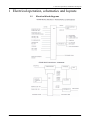
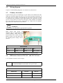
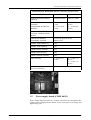
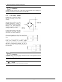
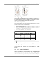
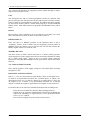
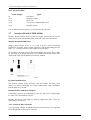
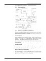
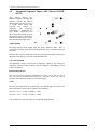
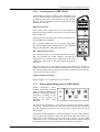
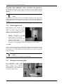
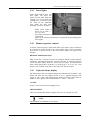
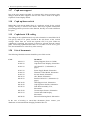
Orthopantomograph®
OP100
Orthoceph®
OC100
Electrical Operation &
Wiring
11/2002
63467-4AB
Copyright
© 2002 by Instrumentarium Imaging
Documentation, trademark and the software are copyrighted with all rights
reserved. Under the copyright laws the documentation may not be copied,
photocopied, reproduced, translated, or reduced to any electronic medium or
machine readable form in whole or part, without the prior written permission
of Instrumentarium Imaging.
Orthopantomograph® and Orthoceph® are registered trademarks of
Instrumentarium Corporation. U.S. patents 4,641,336; 5,016,264; 5,425,065
and 5,444,754. German patent 4,344,745. Orthopantomograph® OP100 and
Orthoceph® OC100 comply with UL and C-UL (File E157261).
The original language of this manual is English.
Instrumentarium Imaging reserves the right to revise this publication from
time to time and to make changes in the content of it without obligation to
notify any person of such revision or changes.
Manufactured by
Instrumentarium Imaging
P.O. Box 20
FIN-04301 Tuusula
FINLAND
Tel. +358 10 394 6500
Fax. +358 10 394 6501
E-mail: [email protected]
Internet: http://www.InstrumentariumImaging.com
Table of Contents
1
Electrical operation, schematics and layouts ................................................... 1
1.1
1.2
1.3
1.4
1.5
Electrical block diagrams ........................................................................................ 1
Wiring diagram........................................................................................................ 2
Primary electronics .................................................................................................. 2
Differences between 230 VAC and 110 VAC use .................................................. 2
Power supply board (CODE 60113)........................................................................ 3
1.5.1 Line voltage jumper ..................................................................................................4
1.5.2 High voltage section ..................................................................................................5
1.5.3 Low voltage section ...................................................................................................5
1.6
1.7
1.8
CPU Board (CODE 60112) ..................................................................................... 5
Interface Board (CODE 60166)............................................................................... 8
X-ray generator........................................................................................................ 9
1.8.1 Filament Control Board (CODE 60114)....................................................................9
1.8.2 Inverter board (CODE 60115) ................................................................................11
1.8.3 Tube head assembly (CODE 66360) .......................................................................13
1.9
1.10
1.11
1.12
1.13
1.14
1.15
1.16
1.17
1.18
1.19
1.20
63467-4AB
Automatic Exposure Timer (AEC) Board (CODE 60122) ................................... 14
Control panel (CODE 61160)................................................................................ 15
Patient positioning panel (CODE 60108).............................................................. 15
Head support lock.................................................................................................. 16
Halogen positioning lights..................................................................................... 16
Laser lights ............................................................................................................ 17
Remote exposure control ....................................................................................... 17
Ceph soft tissue display ......................................................................................... 17
Ceph nose support ................................................................................................. 18
Ceph up/down switch ............................................................................................ 18
Cephalostat L/R coding ......................................................................................... 18
List of documents .................................................................................................. 18
Instrumentarium Imaging
i
ii
Instrumentarium Imaging
63467-4AB
1 Electrical operation, schematics and layouts
1 Electrical operation, schematics and layouts
1.1
63467-4AB
Electrical block diagrams
Instrumentarium Imaging
1
1 Electrical operation, schematics and layouts
1.2
Wiring diagram
Copies of OP100 Wiring diagrams, see section List of Documents.
1.3
Primary electronics
1-phase electric power is fed through a 3-pole cable to the column where the
cable goes inside the right side groove to the vertical carriage (connectors X
101 and X 122). Line filter is located under the lower shelf. Line filter ground
is connected to the incoming 3-pole cable ground. Flat connectors or fixed
screws are used. There are two line filter types: units without CE-marking
have type S-093-4 (code 21297). Units from s/n 72000 with CE-marking:
type S-124-10 or NM-124-10 (code 69025).
WARNING
Always make sure OP100 has a good protective ground.
Main switch with power on
indicator light is located under the
vertical carriage. Main fuses are
located below the vertical carriage.
Both F1 and F2 are slow blow type
for incoming main voltage 110 or
230 Vac:
MAIN FUSES
Fuse
Rating 230 VAC
Rating 110 VAC
Size
F1, F2
10 AT
15 AT
6.3 x 32 mm
Note: In USA/Canada 15AT fuses are used also with 230VAC rating
1.4
Differences between 230 VAC and 110 VAC use
1.4.1 Software version 1.02.07 or higer
Fuses
326 Littelfuse (slow blow) 10A @ 230 VAC, MDA-15
COOPER BUSSMAN (time delay) 15A @ 110 VAC
DIFFERENCES BETWEEN 110 VAC AND 230 VACSW 1.02.07
FEATURE
2
110 VAC
230 VAC
VOLTAGE RANGE
85 - 125
175 - 250
MAIN FUSES
15 AT
10 AT
Instrumentarium Imaging
63467-4AB
1 Electrical operation, schematics and layouts
DIFFERENCES BETWEEN 110 VAC AND 230 VACSW 1.02.07
FEATURE
110 VAC
230 VAC
POWER BOARD JUMPER
SWITCH
ON RIGHT SIDE
ON LEFT SIDE
MANUAL EXPOSURE
VALUES:
PANORAMIC & SPECIAL
MODES
57 - 63 kV, max
16 mA
66 - 85 kV, max
12 mA
57 - 77 kV, max
16 mA
81 - 85 kV, max
12 mA
MANUAL EXPOSURE
VALUES: CEPHALOSTAT
MODE
60 - 85 kV, 12 mA
PREPROGRAMMED
EXPOSURE VALUES
See User Program Pr 53 nor
and Pr52 CCo
READY FOR ORTHO ID
YES
READY FOR DIGIPAN
YES
ORTHO ZONE OPTION
YES
ORTHO TMJ OPTION
YES
ORTHO TRANS OPTION
YES
AEC VALUES
57 - 85 kV, 3.2 12 mA
AEC & MANUAL OFFSET
(Pr 52 CCO density)
1 - 10
1.5
57 - 77 kV, 3.2 16 mA
77 - 85 kV, 3.2 12 mA
Power supply board (CODE 60113)
Power Supply Board rectifies AC voltages and filters the unregulated DC
voltages. Power Supply Board consists of two main parts: low voltage and
high voltage parts.
63467-4AB
Instrumentarium Imaging
3
1 Electrical operation, schematics and layouts
WARNING
Voltages in high voltage part of the power supply board can be deadly. the
peak-to-peak voltage level normally exceeds 600 V.
1.5.1
Line voltage jumper
Jumpers S1 or S2 are for setting
the unit according to local line
voltage:
Switches the rectifier V4 to the
1500uF capacitors C 1 and C 2,
located above the Power Supply
Board, to be either full-wave
rectifier (230 Vac) or half-wave
voltage doubler (110 Vac)
Connects the primary of the line
transformer TF2 either parallel
(230 Vac) or in series (110 Vac)
Connects the primary of the line transformer
TF1 either parallel (230 Vac) or in series (110
Vac)
Connects signal “MAINS” to GND when
110V line voltage is selected. Signal
“MAINS” indicates to the CPU board whether
the unit is connected to nominal 110 Vac or
230 Vac line. This switch will determine the
kV/mA table.
WARNING
The line voltage selection jumper must all be at the correct position; left for
230 VAC and right for 110 VAC
NOTE
Jumper connectors S1 or S2 from unit s/n 71505.
4
Instrumentarium Imaging
63467-4AB
1 Electrical operation, schematics and layouts
1.5.2
High voltage section
In high voltage section (upper half of the PC board) there is a rectifier D 4 for
line voltage and loading circuitry K1-K2-R6 for two capacitors C1 and C2,
which are connected to the PC board through connector X 22.
1.5.3
Low voltage section
In low voltage section (= lower half of the PC board) there are fuses, rectifiers
and filter capacitors for low operating voltages:
•
24 Vac (from transformer TF1) is fused by F2, rectified by D5 (to +34
V) and filtered by C3-C4-C5.
18 Vac (from transformer TF2) is fused by F3, rectified by D6 (to +25
V) and by D7 (to -25 V) and filtered by C7-C8.
12 Vac (from transformer TF2) is fused by F1.
•
•
POWER SUPPLY BOARD FUSES
FUSE
RATING
FUNCTION
SIZE
F1
6.3 AT or 10
AT
+12 VAC
6.3 x 32 mm
F2
6.3 AT
+34 VAC
6.3 x 32 mm
F3
2 AT
+25 V, -25 V
6.3 x 32 mm
NOTE
F1 with 10 AT rating is needed, if the OP100 has with 5 projectors for double
side patient positioning.
List of indicators and test points, see Service Manual Vol.V Trouble
Shooting.
1.6
CPU Board (CODE 60112)
OP100 is a microprocessor controlled equipment. CPU Board monitors and
controls all movements and other operations in OP100, except the Head
support lock operation and Ceph soft tissue display. All key inputs,
microswitches and optocouplers are read by the CPU Board. Accordingly the
63467-4AB
Instrumentarium Imaging
5
1 Electrical operation, schematics and layouts
CPU controls all operations by supplying control signals through it’s input/
output (I/O) and timer circuits.
CPU
The microprocessor and it’s memory/peripheral circuits are common 8-bit
processor design: The microprocessor ICD31 (80C32) has 8 I/O lines; mainly
control signals for control panel by serial link. The address decoding is made
by PAL-circuit ICD25 (22V10). OP100 main program is stored in EPROM
ICD29 (27512, white label) and service programs in EPROM ICD 28 (yellow
label).
RS-232
RS-232 driver ICD37 (MAX232) is for two RS-232 serial links; one serial
link is divided into two links by PAL-circuit ICD25 (22V10).
RESET CIRCUIT
ICA2 (TL7705) is a RESET generator. In the hardware there is also a
“watchdog” feature. If the software does not frequently generate pulses in
WDRFS signal, the voltage at pin 2 of ICA2 falls too low and activates the
RESET signal. Switch S 1 resets the CPU.
TIMER CIRCUITS
The three timers of ICD27 (8254) and timer 2 of ICD25 (8254) generate
clock frequencies for the stepper motor drivers in Interface Board by dividing
the 1.5 MHz clock signal. Timers 0 and 1 of ICD25 (8254) count the
frequencies AECFRQ and MAFRQ from the optoisolators ICD36 and ICD34
(6N136).
+5V VOLTAGE REGULATOR
ICA1 (4962) regulates +5Vdc supply voltage for CPU Board from incoming
unregulated +25V.
PARALLEL INPUTS/OUTPUTS
ICD’s 6, 7, 15 to 18 (74ACT244) are input buffers. There are 40 inputs in use,
of which 4 are optoisolated and there are 8 unused inputs, of which 5 are
optoisolated. ICD’s 9 to 13 and 19 (74HC273) are output drivers. There are
34 outputs in use, of which 15 are optoisolated and there are 14 unused
outputs, of which one output is optoisolated, two outputs are not connected.
I/O from I/O drivers to connectors is buffered and protected according to use:
– Relay drives are buffered by ICD38 (2804, Darlington driver).
– Signals to X-ray generator (Filament Drive Board, Inverter Board and
Tube Head Assembly) are optoisolated by seven quad-optoisolators
ICD’s 1 to 5, 14 and 20.
– Rest of the I/O signals are protected by serial resistors.
6
Instrumentarium Imaging
63467-4AB
1 Electrical operation, schematics and layouts
SERVICE JUMPER
A 3-pin connector X 10 under the
memory chips has a jumper normally
plugged to the right. When the jumper
is moved to the left, it brings the unit
to the Service mode.
OPTION JUMPER
Jumper X 11 is an option switch, normally in “off” position. When switched
“on”, the OP100 can be demonstrated normally, but the exposure is
prevented. This feature can be used eg. in exhibitions.
GROUNDING
There are three separate ground levels in the CPU Board:
1
The actual processor ground level (GND for +5V)
2
The generator ground-level (GND1) from Filament Control Board and
Inverter Board (from connector X 4, pins 22, 23, 25 and 26). Connected
to several optoisolators.
3
AEC-ground level (GND2) from AEC-Board (from connector X 8, pin
12). Connected only to ICD14, pins 9 and 15.
GND is isolated from GND1 and GND2 in CPU Board by optoisolators, to
eliminate noise and RF interference problems, but connected inside the Tube
Head Assembly and in the Power Supply Board.
63467-4AB
Instrumentarium Imaging
7
1 Electrical operation, schematics and layouts
LIST OF SWITCHES:
Swith / Jumper
S1
X 11
X 13
X 10
X 14
Signal
CPU Reset
Normal or Option
Don´t care
User, Service EPROM chip select
Program options
List of indicators and test points, see Troubleshooting Manual.
1.7
Interface Board (CODE 60166)
Interface Board contains driver circuits for stepper motors and DC motors
and drives projector and warning lights, under the control of CPU Board.
STEPPER MOTOR DRIVERS
Stepper motor drivers ICA’s 2, 4, 6 and 8 (L297) convert incoming
frequencies to stepper motor control sequences, and the half-bridge drivers
ICA’s 3, 5, 7 and 9 (L298) drive the stepper motor windings.
It is possible to increase power to the cassette holder down drive. This is done
by removing X 21 jumper. Full power is available for down movement. This
can be used if the cassette holder movement is jammed.
DC MOTOR DRIVERS
The Vertical carriage motor (Z-motor) and the Cassette lift motor (rack
motor) are driven accordingly by circuits around pulse width modulators
ICA10 and ICA11 (TL494).
PROJECTORS, WARNING LIGHTS
Positioning projectors are controlled by relay K1. The X-ray warning lights
L1 and L2 are controlled by relay K2.
Interface board OT: Laser lights are used in Ortho Trans units. Lasers are
controlled by transistor T7.
+15V VOLTAGE REGULATOR
+15V operating voltages for PWM circuits ICA10 and ICA11 are regulated
from unregulated +25V by ICA1 (LM317).
8
Instrumentarium Imaging
63467-4AB
1 Electrical operation, schematics and layouts
List of indicators and test points, see Troubleshooting Manual.
1.8
X-ray generator
1.8.1
Filament Control Board (CODE 60114)
Filament Control Board regulates filament heating level prior to the exposure
(preheat control) and during the exposure (mA control), according to the
digital references controlled by CPU Board.
MA-REFERENCE
Digital mA/preheat reference (signals KVMA0 - KVMA7) is latched to D/A
converter ICA2 (7524) at 20 ms intervals by the negative edge of signal
KVMACLK, while signal KVMASEL is being low at the same time.
The +5V input reference from D 17 (LM336-5.0) is fed to the D/A converter
via a buffer amplifier ICA1 (TL074). The output reference (MAREF) is also
buffered by ICA1.
MA-REGULATOR
PWM (pulse width modulator) ICA3 (TL494) regulates the filament heating
level by adjusting the duty cycle of the driver transistors so that the feedback
voltage at pin 1 is the same as the reference voltage at pin 2.
PWM FEEDBACK MULTIPLEXER
The feedback voltage to the pin 1 of the PWM circuit ICA3 (TL494) comes
through the multiplexer ICD2 (4052). The feedback source (from ICD2)
depends on the control signals PREH and PREHREL:
63467-4AB
Instrumentarium Imaging
9
1 Electrical operation, schematics and layouts
STATUS
preheat
sequence
normal
exposure
(mA-reference
check)
(stand by)
PREH (TP3)
active (0)
active (0)
passive (15V)
passive (15V)
PREHEL
(TP4)
active (0)
passive (15V)
active (0)
passive (15V)
FEEDBACKSOURCE
PREHFB
MAFB
(MAFB)
(MAFB)
FILAMENT TRANSFORMER DRIVE
Pulse Width Modulator ICA3 (TL494) drives the FET switches T1 and T2,
which drive the filament transformer primary. Filament voltage is rectified
and monitored as signal PREHFB.
MA-FEEDBACK MONITORING
CPU is able to check some voltage levels in the Filament Control Board by
reading the frequency MAFRQ in different situations; The voltage to the U/F
converter ICA4 (AD654) comes through the multiplexer ICD2 (4052). The
voltage source (from ICD2) depends on the control signals PREH and
PREHREL:
STATUS
preheat sequence
normal exposure
(mA-reference
check)
(stand by)
PREH (TP3)
PREHREL
(TP4)
active (0)
active (0)
passive (15V)
passive (15V)
active (0)
passive (15V)
active (0)
passive (15V)
VOLTAGESOURCE
MAFB +5V
MAREF
LINEFB
mA References and Feedbacks
mA
Nominal reference [V]
Reference tolerances [V]
Feedback tolerances [V]
2.0
0.48
0.46 - 0.50
0.37 - 0.59
2.5
0.61
0.59 - 0.63
0.50 - 0.72
3.2
0.78
0.76 - 0.80
0.67 - 0.89
4.0
0.97
0.95 - 0.99
0.86 - 1.08
5.0
1.22
1.19 - 1.24
1.11 - 1.32
6.4
1.56
1.52 - 1.59
1.42 - 1.69
8.0
1.94
1.90 - 1.99
1.77 - 2.11
10
2.43
2.38 - 2.48
2.22 - 2.64
10
Instrumentarium Imaging
63467-4AB
1 Electrical operation, schematics and layouts
mA References and Feedbacks
mA
Nominal reference [V]
Reference tolerances [V]
Feedback tolerances [V]
12
2.92
2.85 - 2.98
2.66 - 3.17
16
3.89
3.81 - 3.97
3.54 - 4.24
The frequency MAFRQ is monitored by the CPU Board.
– During preheat sequence CPU is able to measure the mA value (tube
current), which enables the automatic preheat adjustment.
– During normal exposure the CPU is able to calibrate reading of the U/
F converter ICA4 (AD654), since the U/F converter converts +5V
reference into frequency.
– During mA-reference check sequence CPU is able to check the
reference that has been written to the D/A converter ICA2 (7524).
– During stand-by the CPU monitors the LINEFB, which indicates the
line voltage level.
If MAFB does not rise, signal MAOK does not go active during the exposure.
Measure test points on the board:
TP1= GND
TP2 = mAFB
TP4 = mAREF
+/- 15V VOLTAGE REGULATOR
Supply voltages are regulated from unregulated +/- 25V by switching
regulator ICA6 (L4962) for +15V and linear regulator ICA7 (LM337) for
-15V.
List of indicators and test points, see Troubleshooting Manual.
1.8.2
Inverter board (CODE 60115)
Inverter Board regulates kV during the exposure, according to the digital
reference controlled by CPU Board. Inverter Board consists of two main
parts: High voltage section containing the FET bridge, and low voltage
section containing the regulating, reference and pulsing circuits.
WARNING
Voltages in high voltage part of the inverter board can be deadly. The peak-topeak voltage level normally exceeds 600 V.
FET BRIDGE (HIGH VOLTAGE)
The FET-transistors in the H-bridge switch power to the high voltage
transformer in the tubehead assembly. The higher the frequency in the FET
bridge is, the lower the power level (kV*mA) in the tubehead assembly. In
general, FET’s T1, 2, 7 and 8 conduct at the same time, and FET’s 3, 4, 5 and
6 accordingly, at the opposite phase.
63467-4AB
Instrumentarium Imaging
11
1 Electrical operation, schematics and layouts
KV REFERENCE
Digital kV reference (signals KVMA0 - KVMA7) is latched to D/A converter
ICA3 (7524) at 20 ms intervals by the negative edge of signal KVMACLK,
when signal KVMASEL is high at the same time.
The +5V input reference D21 (LM336-5.0) of the D/A converter is buffered
by ICA1 (LM324). The output reference (KVREF) is also buffered by ICA1.
KV REGULATOR
kV regulator consists of KVFB buffer & error amplifier ICA1 (LM324),
frequency modulator & comparator ICA2 (LM339) and pulse shaping circuit
& flip flop ICD2 (4013). kV regulator regulates kV by adjusting the operating
frequency of the high voltage FET bridge.
PULSE TRANSFORMER DRIVE
Drivers ICA4 and ICA5 (SG3635) drive the pulse transformers TF3 and TF4,
which in turn drive the FET-switches of the H-bridge.
KV-FEEDBACK MONITORING
If kVfb does not rise, signal KVOK does not go active during the exposure.
kV references and feedbacks
kV
Nominal reference [V]
Reference tolerances [V]
Feedbacktolerances [V]
57
2.85
2.79 - 2.91
2.75 - 2.95
60
3.00
2.94 - 3.06
2.90 - 3.10
63
3.15
3.08 - 3.22
3.05 - 3.25
66
3.30
3.23 - 3.37
3.20 - 3.40
70
3.50
3.43 - 3.57
3.40 - 3.60
73
3.65
3.57 - 3.73
3.55 - 3.75
77
3.85
3.77 - 3.93
3.75 - 3.95
81
4.05
3.96 - 4.14
3.95 - 4.15
85
4.25
4.16 - 4.34
4.15 - 4.35
Measure test points on the board:
TP17 = GND
TP18 = KVFB
TP19 = KVREF
BACK-UP TIMER
Back-up timer ICA2 (LM339) disables the pulses, if the EXPENA signal is
active for too long period (approximately 22 s).
12
Instrumentarium Imaging
63467-4AB
1 Electrical operation, schematics and layouts
TEST SWITCH
When testing the unit without x-rays, or without kV, TEST switch S, from
board version 1.3 jumper X35, allows the activation of the exposure
sequence and imaging movements regardless of the KVOK feedback.
+15V/+25V SUPPLY VOLTAGES
Supply voltages to Inverter Board are connected via the Filament Control
Board. +25V is only present during exposure (when PREHREL signal is
active in Filament Control Board).
FUSE
High voltage fuse in the Inverter Board, to protect the printed circuit board in
case of short circuits. Fuse rating is 16 AFF, or 10 AT (from August 1994).
INVERTER BOARD FUSE
FUSE
RATING
FUNCTION
SIZE
F1
10 AT or 16
AFF
INCOMING
310 VDC
6.3 x 32 mm
List of indicators and test points, see Troubleshooting Manual.
1.8.3
Tube head assembly (CODE 66360)
WARNING
Voltages inside the tube head assembly are deadly. Maintenance of the tube
head assembly can only be accomplished at the factory. There are no field
serviceable parts inside the tube head assembly, and opening of the tube head
assembly causes non-repairable damage and oil leakage.
Tube head assembly consists of high voltage transformer TF1, voltage
multiplier circuit D1-16 and C1-8, feedback resistors and the tube insert.
TUBE HEAD ASSEMBLY BOARD (CODE 66370)
63467-4AB
Instrumentarium Imaging
13
1 Electrical operation, schematics and layouts
1.9
Automatic Exposure Timer (AEC) Board (CODE
60122)
AEC Board detects the
radiation intensity through the
cassette, converts the current
mode signal from the detectors
to voltage mode signal, and
converts
the
voltage
to
frequency.
The
frequency
(AECFRQ) is monitored by
CPU Board. AEC-board has
three adjustment points and all
adjustments must be done after
OP100 electronics have reached
their operational temperatures.
AMPLIFIERS
Incoming current mode signal from the X-ray detectors D50 - D51 is
converted to voltage mode signal and amplified by ICA1 (AD546) and ICA3
(AD706).
OFFSET R3 is used to adjust the offset for operational amplifiers. It has been
adjusted at the factory for 0 VDC measured from TP1.
U/F CONVERTER
The amplified voltage is converted to frequency signal by the voltage-tofrequency converter ICA4 (AD654), and the frequency (AECFRQ) is wired
to the CPU Board.
BASE FREQUENCY
R27 is used for base frequency adjustment of 5 kHz ± 0.25 kHz at 0 kV /0
mA. The value is measured from TP2 or by using the “Sr 78 Fre” service
program and reading the frequency from the display.
GAIN
R6 is the gain adjustment. It is adjusted by exposing through a special service
tool (code 60441). Gain will be adjusted for as follows:
230 VAC: 73 kV / 12 mA 144 kHz ± 3 kHz
110 VAC: 73 kV / 10 mA 122 kHz ± 3 kHz
List of indicators and test points, see Troubleshooting Manual.
14
Instrumentarium Imaging
63467-4AB
1 Electrical operation, schematics and layouts
1.10
Control panel (CODE 61160)
Control Panel operates as a link between the operator and
the CPU Board. It allows the operator to control OP100,
and displays the status of the equipment to the operator.
Control panel is monitored and controlled from CPU
Board by a serial link.
DISPLAY DATA IN
Serial mode input signals from the CPU Board are
buffered by ICD7 (40106), and wired to decoder circuit
ICD4 (74HC138).
Incoming data is decoded to drive the LED indicators L1L25 through ICD3 (M5450V).
The 7-segment display drive is in a separate piggy-back
pcb. The incoming data is decoded to drive the 7-segment
displays through ICD1 and ICD2 (MC14489).
KEY SWITCH DATA OUT
Key switches S1, S2, S3, S4 and S6 (up-left-down-rightOK) are buffered by ICD6 (40106), decoded and
multiplexed by circuits ICD2 (74HC165) and ICD4
(74HC138), and driven to the CPU Board through the
serial link.
Exposure switch S5 is wired directly to the CPU Board. It is possible to
disable S5 function with Automatic and Manual mode operation. In this case
the exposure with radiation is acticaed via remote control only. See Sr 89 rEo
or Sr 89 COP options for details.
VOLTAGE REGULATOR
Supply voltage +5V is regulated by ICA5 (L4963).
1.11
Patient positioning panel (CODE 60108)
Patient Positioning Panel
includes all the key switches
required when positioning the
patient in OP100. The occlusal
corrections according to the
biting of the patient are
indicated by three LED
indicators.
The three LED indicators H1 - H3 are driven from the CPU Board, and key
switches S1 - S9 are wired to the CPU Board. Pressing any key will ground
the CPU input line. Pressing any key (except “OK”) at power up causes Er 45
InP message.
The Patient Positioning Panel is usually installed to the left hand operation.
For the right hand operation, connect the panel to the right side of the lower
shelf and use the connectors on the right side. Cable C 10 has double
connectors (X 47/L, X 47/R and X 48/L, X 48/R) specially coded to inform
CPU about the panel location. Ortho Trans models have two panels.
63467-4AB
Instrumentarium Imaging
15
1 Electrical operation, schematics and layouts
CPU Board detects whether the panel is installed to the right side by
monitoring signal HOMESIDE in the CPU board. The operation is
automatically switched to right handed configuration: right handed unit lifts
the cassette rack from right and makes the exposure during counterclockwise
rotation.
NOTE
Technically it is possible to have two Patient positioning panels (option code
61248) installed on both sides at the same time. In this case, the operation is
left-handed, unless User Program “Pr 57 Hon” for bi-directional operation is
selected.
1.12
Head support lock
Head Support Lock consists of the
magnet lock and the lock switches.
There are three models for head
support vertical movement: manual,
fixed and fixed with Ortho Trans.
•
•
•
Manual movement is with
friction.It is used in OP/OC100
models outside USA/Canada.
Fixed model is used in OP/OC100
models in USA/Canada.
All Ortho Trans models including
upgrades use a fixed model, where the head support is removable.
+ 25 VDC
Power is received from Power Supply board. When the OP100 power is on,
current is drawn through magnet L2 and the head lock is on. Circuit is opened
by pressing one of the switches S2 or S3 located at the sides of the head
support assembly.
NOTE
CPU does not control the head support lock operation.
1.13
Halogen positioning lights
For
panoramic
and
TMJ
positioning there are three halogen
lights. Lights are controlled
through Interface board. They do
not operate in QA, CEPH nor
TOMO operating modes.
16
Instrumentarium Imaging
63467-4AB
1 Electrical operation, schematics and layouts
1.14
Laser lights
Ortho Trans models have two
laser lights, one above the
mirror and the other under the
rotating cover. Laser lights are
controlled by Interface board
OT. There are not adjustable
parts inside the laser light
assembly. Lasers are lit when
– Ortho Trans opton is
active (Sr 89 COP / 7
P11 “on”) and
– the TOMO collimator is
selected and
– lights on or occlusal correction keys are pressed on positioning panel.
Laser lights
1.15
Remote exposure control
A remote control exposure switch with cable (code 69961) can be connected
to a junction box located at the rear of the column. This switch is normally
open and it is directly wired to the CPU Board. Signals are logical level
voltages.
REMOTE EXPOSURE ONLY
With “Sr 89 rEo” or Sr 89 COP one can configure OP100 so that exposure
(Automatic and Manual Exposure control) can only be initiated from the
remote exposure button. However, Test mode can always be demonstrated
from Control Panel while “Sr 89 rEo” or “Sr 89 COP / 1 rE” is set “on”. This
option is not available with some of the early CPU board versions.
1.16
Ceph soft tissue display
The movement of the nose support changes the trimmer R 30 resistance. This
board will show the nose support travel on two 7 segment displays with
values “0 - 60”, where value represents the distance from the center of the ear
holders to nose support. The actual distance is “value” + “60 mm”.
+25 VDC
Power is received from Power Supply board.
ADJUSTMENTS
There are trimmers R6 and R7 to adjust offset for “0” and gain for “60”.
NOTE
This board has no feedback to CPU board
63467-4AB
Instrumentarium Imaging
17
1 Electrical operation, schematics and layouts
1.17
Ceph nose support
Part of the nose support assembly is a trimmer R30, whose resistance value
changes when the nose support is moved. This value is used as an input to
Ceph Soft Tissue Display Board.
1.18
Ceph up/down switch
Behind the ceph cassette holder there is a up/down switch for the vertical
carriage. This key is wired to CPU board. These keys together with Patient
positioning panel keys have the same function, but they are wired to different
I/O ports.
1.19
Cephalostat L/R coding
The coding for the cephalostat and x-ray tube orientation is controlled with X
110 (pin 4) and X 121 (pin4), located in the side boxes of the vertical
carriage. These lines are wired into separate CPU I/O ports. When no
cephalostat is attached, the program 5 cannot be selected from the control
panel. Connecting cephalostat arm cable CC 2 to either X 110 or X 121 gives
CPU the information to orient X-ray tube correctly.
1.20
List of documents
The following OP100 documents should be part of this section:
Code
68951-1S
60110-3S
60112-3S
60113-3S
60114-3S
60115-3S
60122-3S
60166-3S
60134-4S
60143-4S
66370-3S
60147-4S
60107-3S
60108-4S
Document
Wiring Diagram (from s/n 72000)
Ceph Soft Tissue Display, Schematics
CPU Board V1.5, Schematics (2
pages)
Power Supply Board, Schematics
Filament Control Board, Schematics
Inverter Board, Schematics
AEC Board, Schematics
Interface Board V1.3, Schematics (2
pages)
Head Support Lock, Schematics
Ceph Up/Down Switch, Schematics
Tube Head Assembly V1.4,
Schematics
Cassette Opto Sensors, Schematics
Control Panel and Display,
Schematics
Patient Positioning Panel, Schematics
In the case of missing or out-of-date documents please contact your
distributor or Instrumentarium Imaging Technical Service.
18
Instrumentarium Imaging
63467-4AB
Instrumentarium Imaging Italia S.R.L.
Via Cassanese, 100
20090 Segrate (MI), Italy
Tel. +39 02 21 30 28 1 · Fax +39 02 21 30 28 60
[email protected]
Instrumentarium Imaging is constantly improving its products and reserves the right to
change these specifications without notice.
www.InstrumentariumImaging.com
Instrumentarium Imaging Singapore
152 Beach Road
#12-03A Gateway East
189721 Singapore
Tel. +65 6391 8600 · Fax +65 6396 3009
[email protected]
Instrumentarium Imaging Dental GmbH
P.O.Box 2044, 77680 Kehl am Rhein, Germany
Tel. +49 7851 932 90 · Fax +49 7851 932 930
[email protected]
Distributor:
11/2002 © Instrumentarium Imaging
Instrumentarium Imaging Inc.
300 West Edgerton Avenue, Milwaukee
Wisconsin 53207, USA
Tel. +1 800 558 6120, +1 414 747 1030
Fax +1 414 481 8665
[email protected]
Instrumentarium Imaging France S.A.R.L.
4, Avenue des Roses
94386 Bonneuil Sur Marne Cedex, France
Tel. +33 1 43 39 51 51 · Fax +33 1 43 39 75 75
[email protected]
63467-4AB
Instrumentarium Imaging
P.O.Box 20, FIN-04301 Tuusula, Finland
Tel. +358 10 394 6500 · Fax +358 10 394 6501
[email protected]