1
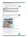
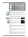
Orthopantomograph®
OP100 D
Orthoceph®
OC100 D
Service Program Manual
For sw. 1.4.11
and sw. 1.4 13
09/2002 64515-4AA
Copyright
© 2002 by Instrumentarium Imaging
Documentation, trademark and the software are copyrighted with all rights
reserved. Under the copyright laws the documentation may not be copied,
photocopied, reproduced, translated, or reduced to any electronic medium or
machine readable form in whole or part, without the prior written permission
of Instrumentarium Imaging.
Orthopantomograph® and Orthoceph® are registered trademarks of Instrumentarium Corporation. U.S. patents 4,641,336; 5,016,264; 5,425,065 and
5,444,754. German patent 4,344,745. Orthopantomograph® OP100 D and
Orthoceph® OC100 D comply with UL and C-UL (File E218408).
The original language of this manual is English.
Instrumentarium Imaging reserves the right to revise this publication from
time to time and to make changes in the content of it without obligation to
notify any person of such revision or changes.
Manufactured by
Instrumentarium Imaging
P.O. Box 20
FIN-04301 Tuusula
FINLAND
Tel. +358 10 394 6500
Fax. +358 10 394 6501
E-mail: [email protected]
Internet: http://www.InstrumentariumImaging.com
Table of Contents
1
Service programs ................................................................................................ 1
1.1
1.2
1.3
1.4
1.5
2
General..................................................................................................................... 1
Exhibition mode ...................................................................................................... 2
SR: general purpose test programs .......................................................................... 3
SR: movement test programs................................................................................... 4
How to use “sr” features.......................................................................................... 4
Service program “SR” features......................................................................... 7
2.1
2.2
2.3
2.4
2.5
2.6
2.7
2.8
2.9
2.10
2.11
2.12
2.13
2.14
2.15
64515-4AA
SR 70 SCR: scroll eeprom contents ........................................................................ 7
SR 74 IOC: cpu input output check......................................................................... 8
SR 75 EPS: exposure without movements ............................................................ 15
SR 76 PUP: warming-up procedure for tubehead ................................................. 15
SR 77 PRH: Preheat automatic adjustment ........................................................... 17
SR 78 FRE: AEC frequency display ..................................................................... 18
SR 79 SUP: line voltage display............................................................................ 18
SR 80 RO-: rotation test without exposure............................................................ 19
SR 81 LI-: linear movement test without exposure............................................... 19
SR 82 CE-: ceph movement test without exposure ............................................... 20
SR 83 RO=: rotation test with exposure & acceleration ....................................... 21
SR 84 LI=: linear movement test with exposure & acceleration........................... 22
SR 86 ROC: rotation test with exposure & constant speed................................... 23
SR 87 LIC: linear movement test with exposure & constant speed ...................... 23
SR 89 COP: country options ................................................................................. 24
Instrumentarium Imaging
i
ii
Instrumentarium Imaging
64515-4AA
1 Service programs
1 Service programs
1.1
General
Orthopantomograph® OP100 D is software controlled diagnostic panoramic
dental x-ray equipment for producing high quality digital images of dentition
and TM-joints.
Software is divided into two parts. User programs (“Pr”) are accessible by
the user and they have features for configuring the unit for daily use and for
changing technique factors to optimize image quality.
Maintenance & Service programs (“Sr”) are for technical people for
installation and service. Tools are required to access “Sr” programs.
This manual covers the features of the “Sr” programs OP100 D software
version 1.4.11. Please refer to the OP100 D User Program Manual V1.4.11
for “Pr” program features.
Letters “Pr” or “Sr” in the kV display indicate that the unit is in the
programming mode. Numbers 50 to 68 and 70 to 89 in the mA display
indicate the actual numeric code for each program. Letters in the exposure
time display indicate the mnemonic explanation for each program, to remind
the user of the actual numeric program code meaning.
After you have set OP100 D for Service mode, different service programs can
be selected by pushing up and down keys, until the desired service program
code appears on the display. The display indicates the service program in the
following form:
64515-4AA
Instrumentarium Imaging
1
1 Service programs
Display
Value(s)
Description
Sr
The unit is in the service mode, and
the serviceman is able to use the service programs to test the unit.
mA
70 - 89
Indicates the actual numeric code for
respective service program. View the
functions with up and down keys and
select with OK key.
s
Scr, IOC, EPS, PUP,
Prh, FrE, SUPro-,
LI-, CE-, ro=, LI=,
roc, LIc, COP
Indicates the alphanumeric short
form for the explanation of the service program, to remind the serviceman what the numeric program code
means.
kV
The displayed service program can be activated by pushing the OK key. After
activating the service program the test starts. In programs which require
movements and / or exposure, the test starts when pushing the exposure
button.
Pas / Err
After completing the test the text “PAS” in time display indicates that the unit
passed the test, or respective failure code “Err” indicates that the test failed.
Repeat the service program or select a new one.
1.2
Exhibition mode
From software version 1.2.07, the OP100D does not emit x-rays, when the
OP100D has been set for exhibition mode. Exhibition mode is selected, when
CPU option switch S2 is set “ON” or option jumper X 11 is set to “ON”.
2
Instrumentarium Imaging
64515-4AA
1 Service programs
1.3
SR: general purpose test programs
GENERAL PURPOSE TESTS REFERENCE TABLE
SCROLL EEPROM CONTENTS
Sr
70
cr
Scroll the failure code counters and the exposure counters of
the CPU EEPROM.
INPUT / OUTPUT
Sr
74
IOC
Operation of CPU input and output signals is monitored and
displayed with control panel’s LED’s.
EXPOSURE WITHOUT MOVEMENTS
Sr
75
EPS
Exposure without imaging movements (the stepping motors
don’t operate).
Sr
76
PUP
WARMING UP SEQUENCE
Sr
77
Prh
PREHEAT ADJUSTMENT
Tube warming up procedure.
Automatic preheat adjustment.
AEC FREQUENCY MONITORING
Sr
78
FrE
Sr
79
SUP
Program displays AEC Board frequencies in time display during the exposure or standby.
LINE VOLTAGE DISPLAY
Displays the line voltage continuously.
COUNTRY OPTIONS
Sr
89
COP
64515-4AA
Remote exposure only, Disable Ceph Collimator, Disable AEC,
Free kV-mA values, Select ceph mA, Ortho Zone, Ortho TMJ
and Ortho Trans
Instrumentarium Imaging
3
1 Service programs
1.4
SR: movement test programs
MOVEMENT TESTS
REFERENCE TABLE
Sr
80
ro-
ROTATION MOVEMENT DYNAMICS
Sr
81
LI-
LINEAR MOVEMENT DYNAMICS
Sr
82
CE-
CEPH MOVEMENT DYNAMICS
Rotation movement test in two directions, no exposure.
Linear movement test in two directions, no exposure.
Ceph movement test in two directions, no exposure.
ROTATION SMOOTHNESS WITH ACCELERATION
Sr
83
ro=
Sr
84
LI=
Rotation movement exposure test, and rotation / focal alignment
verification.
LINEAR MOVEMENT SMOOTHNESS WITH ACCELERATION
Linear movement exposure test.
ROTATION SMOOTHNESS WITH CONSTANT SPEED:
Sr
86
roc
Sr
87
Lic
Rotation movement exposure test, and rotational / focal alignment verification.
LINEAR MOVEMENT SMOOTHNESS WITH CONSTANT
SPEED:
Linear movement exposure test.
NOTE
Movements without exposure are indicated in time display with “ - “,
movements with acceleration with “ = “ and movements with constant speed
are indicated with “ c “.
1.5
How to use “sr” features
Switch the OP100D power off. Remove the Frankfort light knob located
beside the mirror. Open the side doors and remove the mirror cover by
undoing the screws. Lift the cover away.
Locate the 3-pin connector X10 and a 2-pin jumper under the program
memory circuit on the CPU board. Pull out the jumper and insert it to the left
pins. OP100D is now in “SERVICE” mode.
4
Instrumentarium Imaging
64515-4AA
1 Service programs
NOTE
If the jumper is not installed, CPU resets continuously and red LED H2 is
blinking while power is on.
Begin the programming. Switch the OP100D power on. Wait for a moment.
Software version is displayed during the memory check. The display test will
run and numbers from 0 to 9 change on the display. Check that all digits are
lit. “ Sr 75 EPS “ is displayed.
Select one of the “ Sr “ programs. Use up and down keys to view programs ,
press OK key to select.
Make the trouble shooting, adjustments or change settings. Use arrow keys to
select option and settings. Follow the guidelines for each “ Sr “ program
described in the next chapter.
Store any changes to the OP100 D memory. Press OK. “PAS” is displayed
and all indicators are lit. The same program, eg. “Sr 75 EPS”, is displayed
again.
NOTE
If the message “Sy 26 EEP” is displayed, the storing of any changes failed.
Please contact your dealer.
While the OP100 D power is on, you can move between “ Pr “ user program
settings and “ Sr “ service program settings, when needed. Press OK for a
while. Beep is heard and one of the user programs is displayed, eg. “ Pr 50
LAY “. Make changes and store them with OK. Press OK again for a while.
Beep is heard and one of the user programs is displayed, eg. “ Sr 75 EPS “
again.
Exit from service programming. Switch OP100 D power off. Reinsert jumper
X 10 to the right. Refit the mirror cover and Frankfort light knob.
64515-4AA
Instrumentarium Imaging
5
1 Service programs
6
Instrumentarium Imaging
64515-4AA
2 Service program “SR” features
2 Service program “SR” features
2.1
SR 70 SCR: scroll eeprom contents
View the CPU parameter memory (EEPROM) contents. This memory stores
the failure code counters and cumulative exposure counter values and this
information can be used for obtaining OP100D history data. Some failure
counters have have non-zero values at the time of installation. This is normal.
Select the program “ Sr 70 SCR “ and press OK. View memory contents by
pushing the left and right keys. KV display shows the memory location and
mA/s displays show the contents, if any. Table shows different parameters
stored, typical values are shown in parenthesis:
SR 70 SCR: SCROLL MEMORY CONTENTS
kVmA (value)s (value)
**
Last Failure (Sy) or Error (Er) code
number, except Er 40 CPU, Sy 26
EEP and Sy 20 ***.
( no error )
15 or 47
**
***
Failure code counter for CPU failures: Er 40 CPU, Er 41 CPU and Er
42 CPU
(0)
16 or 48
**
***
Failure code counter for line voltage failure Ch 05 *** .
(0)
17 or 49
**
***
Failure code counter for wait-state
warning Sy 20 ***.
( 0-10 )
18 or 50
**
***
Failure code counter for tubehead
thermal switch Sy 21 Hho.
( 0-2 )
19 or 51
**
***
Failure code counter for tubehead
failure Sy 22 ***
(0)
20 or 52*****
Failure code counter for inverter
failure Sy 23 Inu
(0)
21 or 53*****
Failure code counter for filament
failure Sy 24 FIL
(0)
14 or 46
64515-4AA
Memory contents(Typical value)
Instrumentarium Imaging
7
2 Service program “SR” features
SR 70 SCR: SCROLL MEMORY CONTENTS
kVmA (value)s (value)
Memory contents(Typical value)
22 or 54
**
***
EEPROM write cycle counter. Indicates the total number of write
cycles from “Sr” and “Pr” programs
written with “OK” key.
( 200+ )
23 or 55
**
***
Exposure counter value, resetted in
program Pr 61 CLC.
(0)
24 or 56
**
***
CPU non-resetable total exposure
counter .
( 200+ )
25 or 57
**
***
Number of exposures since last service call. Value can be resetted in
program Pr 59 PSE.
( 200+ )
26 or 58
**
***
Arcing counter. Counts single arcs
and after 5 arcs increments Sy 22
*** counter.
( 10+ )
27 or 59
**
***
Exposure count limit, set in Sr 71
PAy
NOTE
After 10,000 write cycles to the EEPROM the kV display shows numbers 46
to 59 indicating a new memory bank: 14 -> 46, 15 -> 47 etc.
Exit this program. Press OK key again. “ Sr 70 SCR “ is displayed again.
Select another program or exit service programs.
2.2
SR 74 IOC: cpu input output check
This program is used for checking the state of the CPU inputs and outputs without opening all the covers of OP100D main assemblies. It is useful for
trouble shooting CPU input signal problems, eg. the various microswitches
and opto couplers.
The program shows whether the signal from some particular switch reaches
the CPU or not. The output signals are somewhat arbitrary, but the
information may be useful in some situations.
Select “ Sr 74 IOC “ and press OK. KV display shows “ In “ for input testing
and time display shows “ 0 “ for first test, and the respective port.
Use arrow keys to select different tests ( 0 to 5 ) and to select input “ In “ or
output “ Ou “ test.
8
Instrumentarium Imaging
64515-4AA
2 Service program “SR” features
Some of the Program selection LED’s on the Control panel are lit showing
the state of the signal port; LED 1 (standard panoramic program) being bit 0
of the port and LED 2 (child panoramic) being bit 1 etc.
Use the tables of the input and output signals with the corresponding I/O port
and bit. Use CPU Board schematics to follow signals and refer also to other
volumes of the Service Manual for various microswitch states.
Note that the control panel display will be updated with a delay. This should
be understood when interpreting movements and other output signals. Stop
the movement by pressing any key to see the correct output status.
After testing return to the program viewing level. Press OK key again. “ Sr 74
IOC “ is displayed again. Select another program or exit service programs.
Sr 74 IOC, Input test “ In 0 “
Cephalostat and Linear Movements
64515-4AA
LED
Signal name
Description (Status, when LED on)
1
EEDO
EEPROM data out. Do not care.
2
cephLIMSW
Cephalostat movement detector
board.(at start/end position)
3
cephMIDSW
Cephalostat movement detector board
(in the middle position)
4
LINLIMSW
Linear (Y) movement limit switch S16
or S17. Switches are connected in parallel. ( Switch triggered in end position
)
5
LINMIDSW
Linear movement middle switch S15.
( Switch triggered )
6
(IN)
Not used, LED not lit
7
(IN)
Not used, LED not lit
8
(IN)
Not used, LED not lit
Instrumentarium Imaging
9
2 Service program “SR” features
Sr 74 IOC, Input test “ In 1”
Patient Positioning Panel Keys
LED
Signal name
Description (LED lit when key pressed)
1
ZUP
Vertical carriage UP button
2
ZDOWN
Vertical carriage DOWN button
3
HOME (LEFT)
Left patient positioning button, if panel
installed on left side
4
HOME (RIGHT)
Right patient positioning button, if panel
installed on right side
5
PROJTRIG
Projector light button
6
PATWARD
Posterior layer correction button / Move
linear movement away from the column
7
CENWARD
Center layer correction button
PILWAR
Anterior layer correction button / Move
linear movement towards the column
8
Sr 74 IOC, Input test “ In 2 “
Mains Voltage, Exposure, Cephalostat, Option
LED
Signal name
Description (LED on)
1
MAINS
110/230 VAC selection on the
power supply board. This is
the switch S4 or jumper connector depending on board version (110 VAC)
2
EXPSW
Exposure switch (pressed)
3
CEPHDOWN
DOWN button on the cephalostat (pressed)
CEPHUP
UP button on the cephalostat
(pressed)
COL1SW
OCD collimator: microswitch
S31 (PAN).OP collimator:
grounded
6
COL2SW
OCD collimator: microswitch
S32 ( CEPH) or OP collimator:
SQA ( QA Filter ) grounded
7
(IN)
Not used, LED not lit
8
OPTIONSW
Switch X 11 or S2 on the CPU
board. ( Exhibition mode )
4
5
10
Instrumentarium Imaging
64515-4AA
2 Service program “SR” features
NOTE
OC100 collimator switches order: QA, PAN, CEPH
Sr 74 IOC, Input test “ In 3 “
Generator Signals
LED
Signal name
Description (LED on)
1
MAOK
Tube current OK. LED should be off
2
KVOK
Tube voltage OK. LED should be off
3
TEMPFAIL
Tube head temperature switch (switch
opened with Sy 21 Hho error message)
4
TUBEFAIL
Tube head high voltage breakdown. (no
breakdown)
5
(IN)
Not used, LED not lit
6
(IN)
Not used, LED not lit
7
(IN)
Not used, LED not lit
8
(IN)
Not used, LED not lit
Sr 74 IOC, Input test “ In 4 “
Movement & Cephalostat
LED
Signal name
Description (LED on)
START
START button from the left or
right patient positioning
panel (pressed)
SIDE
START button from the left
side patient positioning panel
pressed
CEPHL
No cephalostat or cephalostat
on the left side (ceph on the
left)
4
CEPHR
No cephalostat or cephalostat
on the right side (ceph on the
right)
5
(IN)
Not used, LED not lit
6
(IN)
Not used, LED not lit
7
(IN)
Not used, LED not lit
8
(IN)
Not used, LED not lit
1
2
3
64515-4AA
Instrumentarium Imaging
11
2 Service program “SR” features
Sr 74 IOC, Input test “ In 5 “
Remote exposure, Vertical & Rotation Movement
LED
Signal name
Description (LED lit)
1
(IN)
Not used
2
(no name)
Remote exposure button (pressed)
3
ZMIDSW
Vertical carriage height limiting microswitch S
4 (switch triggered at limiting area)
4
ZLIMSW
Vertical carriage limit microswitch S 5 (switch
triggered at end position)
5
ROT1SW
Rotation movement position switch S 11
6
ROT2SW
Rotation movement position switch S 12
7
ROT3SW
Rotation movement position switch S 13
8
ROT4SW
Rotation movement position switch S 14
Sr 74 IOC, Output test “ Ou 0 “
Motor Control Signals
LED
Signal name
Description (LED on)
1
XDIR
Not used (stand-by)
2
XENA
Not used (stand-by)
3
ROTDIR
Rotation movement direction (stand-by)
4
ROTENA
Rotation movement enable (stand-by)
5
CASENA
Not used (stand-by)
6
CASDIR
Not used (stand-by)
7
LINENA
Linear movement enable (stand-by)
8
LINDIR
Linear movement direction (stand-by)
12
Instrumentarium Imaging
64515-4AA
2 Service program “SR” features
Sr 74 IOC, Output test “ Ou 1 “
CPU Board Internal Signals
LED
Signal name
Description (LED lit)
1
EECS
Do not care (stand-by)
2
EESK
Do not care (stand-by)
3
EEDI
Do not care (stand-by)
4
WRDFS
Do not care (stand-by)
5
(OUT)
Not used (stand-by)
6
(OUT)
Not used (stand-by)
7
(OUT)
Not used (stand-by)
8
BEEPER
CPU board beeper (stand-by)
Sr 74 IOC, Output Test “ Ou 2 “
Generator D/A Converter Data
LED
Signal name
Description(LED’s will change all the time)
1
KVMA0
Data bit 0
2
KVMA1
Data bit 1
3
KVMA2
Data bit 2
4
KVMA3
Data bit 3
5
KVMA4
Data bit 4
6
KVMA5
Data bit 5
7
KVMA6
Data bit 6
8
KVMA7
Data bit 7
Sr 74 IOC, Output test “ Ou 3 “
Patient Positioning Panel LED
64515-4AA
LED
Signal name
Description (LED lit)
1
(OUT)
Not used (stand-by)
2
(OUT)
Not used (stand-by)
3
(OUT)
Not used (stand-by)
4
(AEC1)
Not used (stand-by)
5
(AEC2)
Not used (stand-by)
6
PATLED
Patient positioning panel posterior layer correction button LED (no LED)
Instrumentarium Imaging
13
2 Service program “SR” features
Sr 74 IOC, Output test “ Ou 3 “
Patient Positioning Panel LED
7
CENLED
Patient positioning panel center layer button
LED (no LED)
8
PILLED
Patient positioning panel anterior layer correction button LED (no LED)
Sr 74 IOC, Output Test 2 Ou 4 “
Generator Control Signals
LED
Signal name
Description (LED lit)
1
PREHREL
Filament enable (stand-by)
2
PREH
Preheat (stand-by)
3
RG1
Generator input power relay (stand-by)
4
RG
Generator input rectifier capacitor charging
resistor bypass (stand-by)
5
EXPON
High voltage enable (stand-by)
6
KVMASEL
D/A converter select (stand-by)
7
KVMACLK
D/A converter clock (stand-by)
8
(OUT)
Not used (stand-by)
Sr 74 IOC, Output test “ Ou 5 “
Projector Lights, Vertical Movements
LED
Signal name
Description (LED lit)
1
PROJLIT
Projector light enable (lights off)
2
RACKDIR
Not used (stand-by)
3
RACKENA
Not used (stand-by)
4
ZDIR
Vertical carriage movement direction (up)
5
ZENA
Vertical carriage movement enable
6
(OUT)
Not used (stand-by)
7
(OUT)
Not used (stand-by)
8
(LASLIT)
Not used (stand-by)
14
Instrumentarium Imaging
64515-4AA
2 Service program “SR” features
2.3
SR 75 EPS: exposure without movements
WARNING
This special program generates x-rays.
Exposure without movements. Stepping motors do not operate during the
exposure cycle. This program can be used while doing electrical
troubleshooting or calibration. User program “ PR 68 INS “ has the same
features as this Service program.
NOTE
When this program is used, the KVOK and MAOK signals are not monitored.
Therefore Sy 23 Inu and Sy 24 FIL error codes are not enabled. Only Sy 22
*** error code is monitored.
Procedure:
Select “ Sr 75 EPS “ and press . Preselected technique factors are displayed.
Select the technique factors, kV, mA and exposure time. Make the exposure.
Unit can be operated, but there are no imaging movements during the
exposure.
NOTE
If this program is used to align cephalometric beam, make sure that OC100D
is positioned in User mode for cephalometric exposures (Program 5 -> ceph
collimator -> movement button) before entering this program.
After the exposure the unit is ready for additional exposures.
Return to the program viewing level. Press key again. “ Sr 75 EPS “ is
displayed again. Select another program or exit service programs.
2.4
SR 76 PUP: warming-up procedure for tubehead
WARNING
This special program generates x-rays.
Purpose of this program is to enable testing of a defective tubehead assembly,
or warming up procedure of the replacement of tubehead assembly.
Procedure:
Select program “ Sr 76 PUP “. Make the exposure. OP 100 D exposes with
the lowest kV / mA values.
64515-4AA
Instrumentarium Imaging
15
2 Service program “SR” features
Repeat the exposure. No wait between the exposures is necessary. The next
exposure can be taken right after the previous one. kV / mA starts rising
automatically from 20 kV / 1 mA, one step after each 3.2 s exposure, until
85kV / 12mA is reached:
Sr 76 PUP: kV & mA Feedback Reference Voltages
kV
mA
s
(VkVref)
(VmAref)
20
1.0
3.2
(1.00 V)
(0.24 V)
30
1.0
3.2
(1.50 V)
(0.24 V)
40
1.0
3.2
(2.00 V)
(0.24 V)
50
1.0
3.2
(2.50 V)
(0.24 V)
54
1.0
3.2
(2.70 V)
(0.24 V)
57
1.0
3.2
(2.85 V)
(0.24 V)
60
1.0
3.2
(3.00 V)
(0.24 V)
63
1.0
3.2
(3.15 V)
(0.24 V)
66
1.0
3.2
(3.30 V)
(0.24 V)
70
1.0
3.2
(3.50 V)
(0.24 V)
73
1.0
3.2
(3.65 V)
(0.24 V)
77
1.0
3.2
(3.85 V)
(0.24 V)
81
1.0
3.2
(4.05 V)
(0.24 V)
85
1.0
3.2
(4.25 V)
(0.24 V)
85
2.0
3.2
(4.25 V)
(0.49 V)
85
2.5
3.2
(4.25 V)
(0.61 V)
85
3.2
3.2
(4.25 V)
(0.78 V)
85
4.0
3.2
(4.25 V)
(0.97 V)
85
5.0
3.2
(4.25 V)
(1.22 V)
85
6.4
3.2
(4.25 V)
(1.56 V)
85
8.0
3.2
(4.25 V)
(1.94 V)
85
10.0
3.2
(4.25 V)
(2.43 V)
85
12.0
3.2
(4.25 V)
(2.92 V)
Complete one exposure by each technique factors listed above. In case of
arcing and / or breakdown, start this test from the beginning (by pushing the
“OK”-button twice).
If an arc or high voltage breakdown occurs in the tubehead during exposure,
this program is terminated and an “Err” failure code will appear on the
display.
16
Instrumentarium Imaging
64515-4AA
2 Service program “SR” features
When the complete Warming-up procedure has been accomplished, a
message “PAS” will appear on the time display.
If repetitive arcing and/or breakdowns occurred, consult Instrumentarium
Imaging Technical Service.
NOTE
It is also recommended that the OP100D, which has not been used for 3
months or more, should be warmed up with this program. Always run this
program after the tube head assembly replacement.
Return to the program viewing level. Press OK key again. “ Sr 76 PUP “ is
displayed again.
After the test set the OP100D for normal operation and make a panoramic
exposure (Program 1) with maximum technique factors.
2.5
SR 77 PRH: Preheat automatic adjustment
WARNING
This special program generates x-rays.
Purpose of this program is to make the unit to adjust it’s preheat level of the
filament automatically.
Procedure:
Select the program Sr77Prh and push the exposure button continuously. Unit
makes an exposure with 85 kV.
Preheat level starts to rise from 0 by increasing preheat reference slowly, and
the unit checks the mA level at the same time. The preheat reference data is
displayed in the time display. High number indicates low reference.
NOTE
After the exposure the preheat value which is normally between 190 and 200
appears on the display.
When the desired mA level is reached, program terminates the exposure.
Press OK to store the current preheat reference into the EEPROM memory.
“ PAS “ appears to the time display accordingly after the program has been
completed. If “ Err “ was displayed, try again.
Return to the program viewing level. Press OK key again. “ Sr 77 PRH “ is
displayed again. Select another program or exit service programs.
64515-4AA
Instrumentarium Imaging
17
2 Service program “SR” features
2.6
SR 78 FRE: AEC frequency display
WARNING
This special program generates x-rays.
Purpose of this program is to verify the calibrated frequency of the PAN AEC
terminal Board by monitoring the AEC frequency and during the exposure.
User program “ Pr 68 INS “ has the same features as this program.
This program eliminates the need of oscilloscope or frequency counter when
adjusting frequency of the AEC. It is also used to calibrate the AEC terminal
Board, refer to OP100D Technical Support Manual for more details on AEC
calibration.
Procedure:
Select program “ Sr 78 FrE “. Technique factors 73kV and 12mA should be
selected and time display shows ---.--.---.
Make exposure and response frequency (signal AECFRQ) from AEC
terminal Board appears on time-display (unit kHz).
NOTE
If there is no filtering (eg. Al calibration tool missing) between THA and
CCD sensor, the displayed frequency might increase rapidly resulting to zeros
on display.
This frequency can be adjusted from the PAN AEC terminal board. Refer to
OP100D Technical Support Manual section “AEC Calibration Procedure” for
details.
Return to the program viewing level. Press OK key again. “ Sr 78 FRE “ is
displayed again. Select another program or exit service programs.
2.7
SR 79 SUP: line voltage display
Line voltage is monitored by measuring the incoming +25V supply in the
Filament Control Board. Measured line voltage is shown on the time display.
Procedure:
Select program “ Sr 79 SUP “. The display shows the approximate line
voltage value:
Inaccuracy of Line Voltage Measurement
Inaccuracy of Line Voltage Measurement
230 VAC Line
110 VAC Line
± 5 VAC
± 3 VAC
18
Instrumentarium Imaging
64515-4AA
2 Service program “SR” features
Return to the program viewing level. Press OK key again. “ Sr 79 SUP “ is
displayed again. Select another program or exit service programs.
2.8
SR 80 RO-: rotation test without exposure
Purpose of this program is to check that there is enough torque in the
rotational movement: the stepping motor and motor control circuit operate
properly, there is enough friction and the movement does not slip nor get
stuck. Rotation test can be done in clockwise - counterclockwise and vice
versa.
Procedure:
Select program “ Sr 80 ro- “. Movement test is activated by pushing the
exposure button.
Movement is driven from start to end by varying speed. Then the movement
is driven from end to start by constant, slow speed, and at the same time the
CPU checks whether the pulse count of the stepping motor remains the same,
to detect whether some pulses were lost during accelerative movements.
Display shows the actual rotation in degrees, from “ 0º “ to “ 200º “ and back.
Note that figure “ 1.5 “ indicates that the motor is loosing pulses during
acceleration that correspond to 1.5º rotation, and “ -1.5 “ indicates that the
drive mechanics is sliding during braking sequence that correspond to 1.5º
rotation.
Press OK key. “ PAS “ or “ Err “ message appears to the time display
accordingly after the program has been completed. Test tolerance is ± 1 % or
± 2º.
If the test failed and “ Err “ was displayed, check the microswitches, friction
surface, drive wheel and its tension, stepping motor and its driving circuitry,
cable C 13 inside the rotating unit.
Repeat the test when needed or return to the program viewing level by
pushing OK key again.
2.9
SR 81 LI-: linear movement test without exposure
Purpose of this program is to check that there is enough power in the linear
movement: the stepping motor and it’s drive operate properly, and the
movement does not get stuck. This test can be done in two directions: towards
the column and back or vice versa.
Procedure:
Select program “ Sr 81 LI- “. Enter the program by pushing the OK button
untill the unit stops beeping. Movement test is activated by pushing the
exposure button.
Movement is driven from start to end by varying speed. Then the movement
is driven from end to start by constant, slow speed, and at the same time the
CPU checks whether the pulse count of the stepping motor remains the same,
to detect whether some pulses were lost during accelerative movements.
Display shows the actual linear movement travel (in mm) of “ 0 “ to “ 60 “
and back. Note that a figure “ 0.4 “ indicates that the motor is loosing pulses
during acceleration that correspond to 0.4 mm travel, and “ -0.4 “ indicates,
64515-4AA
Instrumentarium Imaging
19
2 Service program “SR” features
that the drive mechanics are sliding during the braking sequence
corresponding to the 0.4 mm travel.
Press OK key. “ PAS “ or “ Err “ message appears to the time display
accordingly after the program has been completed. Test tolerance is ± 2 % or
± 1.2 mm.
If the test failed and “Err” was displayed, check the microswitches, alignment
of the fly wheel, linear actuator and linear plate, stepping motor and its
driving circuitry.
Repeat the test when needed or return to the program viewing level by
pushing OK key again.
2.10
SR 82 CE-: ceph movement test without exposure
Purpose of this program is to check that there is enough power in the ceph
movement: the stepping motor and it’s drive operate properly.
Procedure:
Select program “ Sr 82 CE- “. Enter the program by pushing the OK button
untill the unit stops beeping. Movement test is activated by pushing the
exposure button.
Movement is driven from start to end by varying speed. Then the movement
is driven from end to start by constant, slow speed, and at the same time the
CPU checks whether the pulse count of the stepper motor remains the same,
to detect whether some pulses were lost during accelerative movements.
Display shows the actual ceph movement in mm, from “ 0 “ to “ 260 “. Total
travel is 260 mm. Note that figure “ 0.5 “ indicates that the motor is loosing
pulses during acceleration corresponding to 0.5 mm travel, and “-0.5”
indicates that the drive mechanics is sliding during braking sequence
corresponding to 0.5 mm travel.
Press OK key. “ PAS “ or “ Err “ message appears to the time display
accordingly after the program has been completed. Test tolerance is ± 1mm.
If the test failed and “ Err “ was displayed, check the microswitches or opto
couplers, friction surface, drive wheel and its tension, stepping motor and its
driving circuitry.
Repeat the test when needed or return to the program viewing level by
pushing OK key again.
20
Instrumentarium Imaging
64515-4AA
2 Service program “SR” features
2.11
SR 83 RO=: rotation test with exposure &
acceleration
CAUTION
This special program generates x-rays.
Purpose of this program is to check the smoothness of the rotation movement,
and that there are no stripes in the image because of vibrations.
Procedure:
Select program “ Sr 83 ro= “. Enter the program by pushing the OK button
untill the unit stops beeping. Maximum technique factors are displayed.
Install an x-ray film (in a cardboard sheet or envelope) horizontally on top of
the chin support. Mark the film orientation by bending the envelope from the
corner. Use some weight over the envelope.
Rotate by hand to see that the cassette holder or the tube head assembly does
not touch the film.
Use technique factors displayed or select new ones. Unit will start about 40
kV lower than this initial setting, raise kV’s and lower again to compensate
film density due to the changes in movement speed.
64515-4AA
Instrumentarium Imaging
21
2 Service program “SR” features
Make the exposure by pushing the exposure button.
Process the film and check that there are no sharp stripes. Some vague stripes
may be seen. An excellent film is all gray. Repeat the test when needed.
Return to the program viewing level by pushing OK key again.
2.12
SR 84 LI=: linear movement test with exposure &
acceleration
CAUTION
This special program generates x-rays.
Purpose of this program is to check the smoothness of the linear movement,
and that there are no stripes in the image because of vibrations.
Procedure:
Select program “ Sr 84 LI= “. Enter the program by pushing the OK button
untill the unit stops beeping. Initial technique factors, eg. 66/8.0/4 are
displayed. Actual values displayed will dedend on the Pr 52 CCO contrast
and density settings for imaging program P1.
Install a loaded cassette, or envelope test film, vertically on top of the chin
support. Notice the tube side. Use tape to secure the cassette.
Use technique factors displayed or select new ones. Unit will start about 40
kV lower than this initial setting, raise kV’s and lower again to compensate
film density due to the changes in movement speed.
Make an exposure by pushing the exposure button.
Process the film and check that there are no sharp stripes. Some vague stripes
may be seen. An excellent film is all gray.
Return to the program viewing level by pushing OK key again.
22
Instrumentarium Imaging
64515-4AA
2 Service program “SR” features
2.13
SR 86 ROC: rotation test with exposure &
constant speed
CAUTION
This special program generates x-rays.
Purpose of this program is to check the smoothness of the rotation movement,
and that there are no stripes in the image because of vibrations.
Procedure:
Select program “ Sr 86 roc “. Enter the program by pushing the OK button
untill the unit stops beeping. Technique factors 85/12/100 @ 230 VAC (85/8/
100 @ 110 VAC) are displayed. Light is blinking on time display.
Install an x-ray film (in a cardboard sheet or envelope) horizontally on top of
the chin support. Mark the film orientation by bending the envelope from the
corner.
Use technique factors displayed or select new ones. Exposure time is fixed 10
s, the number in time display, eg. “100” is used to set the motor speed. A
smaller number corresponds to faster speed and vice versa. Make an exposure
by pushing the exposure button.
NOTE
The exposure will terminate prior to set time if the movement hits the
mechanical limit.
Process the film and check that there are no sharp stripes. Some vague stripes
may be visible.
Return to the program viewing level by pushing key again.
2.14
SR 87 LIC: linear movement test with exposure &
constant speed
CAUTION
This special program generates x-rays.
Purpose of this program is to check the smoothness of the linear movement,
and that there are no stripes in the image because of vibrations.
Procedure:
Select program “Sr 87 LIc”. Enter the program by pushing the OK button
untill the unit stops beeping. Technique factors 73/12/100 @ 230 VAC (77/
10/100 @ 110 VAC) are displayed.
Install a loaded cassette vertically on top of the chin support.
64515-4AA
Instrumentarium Imaging
23
2 Service program “SR” features
Use technique factors displayed or select new ones. Exposure time is fixed 5
s, the number in time display, eg. “100” is used to set the motor speed. A
smaller number corresponds to faster speed and vice versa. Make an exposure
by pushing the exposure button.
NOTE
The exposure will terminate prior to set time if the movement hits the
mechanical limit.
Process the film and check that there are no sharp stripes. Some vague stripes
may be visible.
Return to the program viewing level by pushing OK key again.
2.15
SR 89 COP: country options
Seven country option programs, which are one time settings to configure the
unit for daily operation. There are four options that can be selected for:
Remote exposure only “1 rE”, disable first cephalostat collimator “2 C1”, no
AEC for OP 100 used in computerized radiography “3 nA” and free kV
selection in steps of 1 kV “4 FE”.
Sr 89 COP: COUNTRY OPTIONS
Program
1
rE
2
nA
3
FE
4
P3
24
Option
Function
OFF
Exposure from Control Panel and Remote Exposure button.
on
Remote Exposure only with AEC and Manual
mode . Test mode from Remote Exposure button
and Control Panel.
OFF
Normal operation with AEC.
on
No AEC. OP100 CR models without AEC. Denies
the AEC operation. Allows OP 100 CR to be used
without AEC in phosphor plate digital imaging.
OFF
KV and mA selected in pairs according to Pr 52
CCO settings.
on
Free Exposure Selection. Selection of 57 - 85 kV
in steps of 1 kV in Manual Mode and mA selection from the table: 2.5 - 3.2 - 4.0 - 5.0 - 6.4 - 8.0 10 - 12 - 16.
OFF
Wide Layer Panoramic Program P3.
on
Password -> Ortho Zone Panoramic Program P3
with enhanced lateral TMJ views and very wide
anterior layer view.
Instrumentarium Imaging
64515-4AA
2 Service program “SR” features
Sr 89 COP: COUNTRY OPTIONS
5
OL
6
3D
7
Or
OFF
Lateral TMJ Imaging programs P8.
on
Password -> Optional Axial corrected Ortho TMJ
optional imaging program.
OFF
No function, future use.
on
No function, future use.
OFF
No function, future use.
on
No function, future use.
Procedure:
Select program “ Sr 89 COP “.Enter the program by pushing the OK button
untill the unit stops beeping. Press OK. Displays show “ 1 “ and “ rE “ and
time display shows “ OFF “ or “ on “. The kV/mA light is blinking.
Select one of the country option programs “ 1 rE “, “ 2 C1 “, “ 3 nA “ or “ 4
FE “ by pressing right or left arrow keys. These four programs are all the time
available.
If you have the correct password, one of the additional options comes visible:
“ 5 P3 “ for Ortho Zone, “ 6 P6 “ for Ortho TMJ or “ 7 P11 “ for Ortho Trans.
Change the setting of the respective program in displays
by first pressing down key. Light in the time display is
blinking. Press right key to activate this feature. “ on “ is
displayed.
Press left key, if you don’t want this feature. “ OFF “ is
displayed.
Press OK to store any changes into OP 100 memory. OP
100 will light all indicators and display “ PAS “
momentarily and then “ Sr 89 COP “ again.
1 rE (OFF/on):
Prevents the exposure from control panel during exposure cycles in AEC and
Manual modes. When selected, the exposure is initiated with remote
exposure button only. This feature has no affect in Test mode or in Service
Mode.
2 nA (OFF/on):
No AEC. Disables AEC function. OP 100 can be used without AEC Board,
eg. OP 100 CR models for computerized radiography with a special image
plate system do not have AEC.
3 FE (OFF/on):
Free selection of kV values in Manual mode regardless of the nominal factor
selection path (= Pr 52 CCo). This feature has no effect on the AEC mode and
on preprogrammed technique factors. and mA can be selected from the fixed
table (2.0, 2.5, 3.2, 4.0, 5.0, 6.4, 8.0, 10, 12, 16).
64515-4AA
Instrumentarium Imaging
25
2 Service program “SR” features
In Manual mode kV can be selected in steps of 1 kV. When the led indicator
for kV/mA values is lit, first kV display is blinking. Select kV value by
pressing right or left keys.
NOTE
Pressing the key longer causes kV to change in larger steps.
Then press down key. MA display is blinking. Select the mA value.
NOTE
Cephalostat has fixed mA value.
NOTE
If the kV is increased with maximum mA selection, the mA value is
automatically decreased when the product of kV * mA exceeds the allowed
X-ray tube rating.
4 P3 (OFF/on):
Use “ SR 73 LOC “ to enter the password. If the password was correct, Ortho
Zone can be activated by selecting “ on “ or deactivated by selecting “ OFF “.
If the password was incorrect, one cannot access this option.
5 OL (OFF/on):
Use “ SR 73 LOC “ to enter the password. If the password was correct, Ortho
TMJ can be activated by selecting “ on “ or deactivated by selecting “ OFF “.
If the password was incorrect, one cannot access this option.
6 3D (OFF/on):
Use “ SR 73 LOC “ to enter the password. If the password was correct,
OTACT can be activated by selecting “ on “ or deactivated by selecting “
OFF “. If the password was incorrect, one cannot access this option.
7 Or (OFF/on):
Use “ SR 73 LOC “ to enter the password. If the password was correct, Ortho
Trans can be activated by selecting “ on “ or deactivated by selecting “ OFF “.
If the password was incorrect, one cannot access this option.
26
Instrumentarium Imaging
64515-4AA
Instrumentarium Imaging Italia S.R.L.
Via Cassanese, 100
20090 Segrate (MI), Italy
Tel. +39 02 21 30 28 1 · Fax +39 02 21 30 28 60
[email protected]
Instrumentarium Imaging is constantly improving its products and reserves the right to
change these specifications without notice.
www.InstrumentariumImaging.com
Instrumentarium Imaging Singapore
152 Beach Road
#12-03A Gateway East
189721 Singapore
Tel. +65 6391 8600 · Fax +65 6396 3009
[email protected]
Instrumentarium Imaging Dental GmbH
P.O.Box 2044, 77680 Kehl am Rhein, Germany
Tel. +49 7851 932 90 · Fax +49 7851 932 930
[email protected]
Distributor:
09/2002 © Instrumentarium Imaging
Instrumentarium Imaging Inc.
300 West Edgerton Avenue, Milwaukee
Wisconsin 53207, USA
Tel. +1 800 558 6120, +1 414 747 1030
Fax +1 414 481 8665
[email protected]
Instrumentarium Imaging France S.A.R.L.
4, Avenue des Roses
94386 Bonneuil Sur Marne Cedex, France
Tel. +33 1 43 39 51 51 · Fax +33 1 43 39 75 75
[email protected]
64515-4AA
Instrumentarium Imaging
P.O.Box 20, FIN-04301 Tuusula, Finland
Tel. +358 10 394 6500 · Fax +358 10 394 6501
[email protected]