1
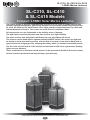
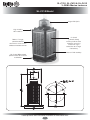
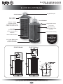
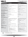
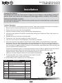
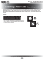
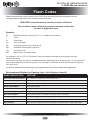
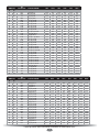
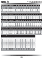
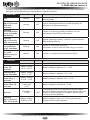
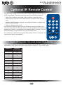
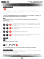
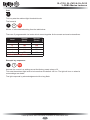
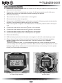
SL-C310, SL-C410 & SL-C415
Marine Lanterns
Installation & Service Manual
Version 3.4
Version No.
1.0
1.1
1.2
1.3
1.4
2.0
3.0
3.1
3.2
3.3
3.4
Description
Manual Launch: SL-C410 added & IR Control
Addition of Configuration Settings Information
Configuration Settings update
Addition of LUX Table
Update to Max Intensities & Addition of Automatic Intensity Reduction
GPS as standard
Lantern Operation Update, Specs & GSM
(SL-C410)
IR Controller functions
Update: Selecting an intensity/power setting
Update: GPS Synchronisation
Torque setting
SL-C415
Update: IR Storage Mode, IR Operational Mode
TOC
Date
March 2012
April 2012
April 2012
April 2012
June 2012
Approved
C. Procter
S. Turner
C. Procter
J. Dore
C. Procter
Nov 2012
January 2014
C. Procter
P. Rainey/
Y. Chambers/
S. Turner
S. Turner
Y. Chambers
P. Rainey
C. Procter
January 2014
February 2014
November 2014
March 2015
S. Turner
J. Dore
SL-C310, SL-C410 & SL-C415
3–5NM+ Marine Lanterns
Table of Contents
Introduction........................................................................................................ Page 4
Operating Principle........................................................................................... Page 4
Technology......................................................................................................... Page 4
SL-C310, SL-C410 & SL-C415 Models............................................................. Page 5
SL-C310 Model.............................................................................................. Page 6
SL-C410 & SL-C415 Models......................................................................... Page 8
Installation ....................................................................................................... Page 10
Selecting an Intensity/Power Setting ........................................................... Page 11
Selecting a Flash Code................................................................................... Page 12
Flash Codes..................................................................................................... Page 13
GPS Synchronisation...................................................................................... Page 18
Lantern Status................................................................................................. Page 19
Optional IR Remote Control........................................................................... Page 21
Sealite IR Controller / Universal Remote Compatibility............................... Page 21
IR Controller Functions................................................................................... Page 22
Test Mode / Configure.................................................................................. Page 22
Normal Operation........................................................................................ Page 22
Read............................................................................................................ Page 22
Flash Code.................................................................................................. Page 22
Flash Code Numbers................................................................................... Page 22
Intensity....................................................................................................... Page 23
Battery Status.............................................................................................. Page 23.
Operational Mode........................................................................................ Page 23
Lux............................................................................................................... Page 24
Error / Acknowledge Indication.................................................................... Page 25
Configuration Settings................................................................................. Page 25
Hibernation Mode (Advanced Users)........................................................... Page 26
Storage Mode (Advanced Users)................................................................ Page 28
Optional GSM Monitoring & Control System (SL-C410 & SL-C415)........... Page 29
Maintenance & Servicing................................................................................ Page 30
Replacing the Battery.................................................................................. Page 30
Long Term Battery Storage.......................................................................... Page 30
Solar Panel Replacement............................................................................ Page 31
How to Change the Regulator..................................................................... Page 32
Trouble Shooting............................................................................................. Page 33
Sealite LED Light Warranty............................................................................ Page 34
Latest products and information available at www.sealite.com
3
SL-C310, SL-C410 & SL-C415
3–5NM+ Marine Lanterns
Introduction
Congratulations! By choosing to purchase a Sealite lantern you have become the owner of
one of the most advanced LED marine lanterns in the world.
Sealite Pty Ltd has been manufacturing lanterns for over 25 years, and particular care has been taken to
ensure your lantern gives years of service.
As a commitment to producing the highest quality products for our customers, Sealite has been independently
certified as complying with the requirements of ISO9001:2008 quality management system.
Sealite lanterns comply with requirements of the US Coast Guard in 33 CFR part 66 for Private Aids To
Navigation.
By taking a few moments to browse through this booklet, you will become familiar with the versatility of your
lantern, and be able to maximise its operating function.
Operating Principle
The solar module of the lantern converts sunlight to an electrical current that is used to charge the battery. The
battery provides power to operate the lantern at night.
The flasher unit has very low current requirements. A microprocessor drives an ultra bright LED through a
DC/DC converter, which enables the LED to operate within the manufacturer’s specifications. The battery is
protected from over-charging within the circuit to ensure maximum battery life.
On darkness, the microprocessor will initiate a program check and after approximately 1 minute begin flashing
to the set code
Technology
Sealite is the world’s fastest growing manufacturer of marine aids to navigation. We
employ leading mechanical, optical, hardware & software engineers to create innovative
products to service the needs of our customers worldwide, and offer the widest range of
solar-powered LED lanterns in the marketplace.
Electronics
Sealite employs leading in-house electronic engineers in the design and development of software and related
circuitry. All individual electronic components are sourced directly by Sealite procurement staff ensuring that
only the highest quality components are used in our products.
LED Technology
All marine lanterns use the latest advancements in LED (Light Emitting Diode) technology as a light source.
The major advantage of LED’s over traditional light sources is well established in that they typically have an
operational life in excess of 100,000 hours, resulting in substantial savings to maintenance and servicing
costs.
Precision Construction
Commitment to investing in the design and construction of injection-moulded parts including optic lenses, light
bases and a range of other components ensures that all Sealite products are of a consistent & superior quality.
Optical Performance
Sealite manufactures a range of marine LED lenses moulded from multi-cavity dies. The company has
superior in-house lens manufacturing capabilities to support outstanding optical performance.
Award-winning, Patented Technology
Several United States and Australian patent registrations are held on Sealite’s range of innovative designs,
with other regional patents pending in Canada, United Kingdom and Europe.
Latest products and information available at www.sealite.com
4
SL-C310, SL-C410 & SL-C415
3–5NM+ Marine Lanterns
SL-C310, SL-C410
& SL-C415 Models
Compact 3-5NM+ Solar Marine Lanterns
The robust design of this self-contained light ensures up to 12 years of reliable service with
minimal ongoing maintenance. Specifically designed to survive the harshest environment the
SL-C310, SL-C410 and SL-C415 feature seven stage powder coated aluminium Top, Base and
Internal Aluminium Chassis. The corners are made from UV stabilised rubber.
All components are user-replaceable in the unlikely event of damage.
The high impact resistant polycarbonate lens ensures even light visibility.
The three and four hole bolt pattern will fit directly onto any 200mm OD mount.
The lanterns can be fitted with an optional external ON/OFF switch; this means the light can
be turned on once mounted in position, with the flick of a switch. It can also be fitted with an
optional external charging port for charging the battery while it is stored for extended periods.
The SL-C310. SL-C410 and SL-C415 models are fitted with a GPS unit to synchronise flashing
lights over any distance.
These models have an IR sensor which allows it to be operated via Sealite’s IR remote control.
All this is backed by Sealite’s industry leading 3-year warranty.
Latest products and information available at www.sealite.com
5
SL-C310, SL-C410 & SL-C415
3–5NM+ Marine Lanterns
SL-C310 Model
Single LED Optic
High visibility
IALA colours
4 x 3watt
(12watts total)
multicrystalline solar
modules, ensuring
maximum light
collection to charge
the battery
Robust 7-stage
powder-coated
aluminium chassis with
rubber extruded corners
Internal 12Ah battery
3 & 4 hole 200mm bolt
pattern base for ease of
installation
Latest products and information available at www.sealite.com
6
SL-C310, SL-C410 & SL-C415
3–5NM+ Marine Lanterns
SPECIFICATIONS•*
SL-C310
Light Characteristics
Light Source
Available Colours
Typical Maximum Flashing Intensity
(cd)†
Visible Range (NM)
LED
Red, Green, White, Yellow, Blue
Red - 121 Green - 88 White - 156 Yellow - 95
Horizontal Output (degrees)
Vertical Divergence (degrees)
Available Flash Characteristics
Intensity Adjustments
LED Life Expectancy (hours)
AT @ 0.74: 3–5+
AT @ 0.85: 3.5–6.3+
360
>7
Up to 256 IALA recommended (user adjustable)
Multiple intensity settings
>100,000
Current Draw (mA)
Circuit Protection
Nominal Voltage (V)
Autonomy (nights)
Temperature Range
Refer to Sealite Power Calculator
Integrated
12
>60 (14 hour darkness, 12.5% duty cycle)
-40 to 80°C
Solar Module Type
Output (watts)
Charging Regulation
Multicrystalline
12 (4 x 3watt)
Microprocessor controlled
Battery Type
Battery Capacity (Ah)
Nominal Voltage (V)
Gel SLA
12
12
Body Material
Lens Material
Lens Diameter (mm/inches)
Lens Design
Mounting
Height (mm/inches)
Width (mm/inches)
Mass (kg/lbs)
Product Life Expectancy
7-stage powder-coated aluminium chassis with UV-stabilised rubber
corners & gaskets
LEXAN® Polycarbonate – UV-stabilised
98 / 37/8
Single LED Optic
3 & 4 hole 200mm bolt pattern
433 / 17
233 / 91/5
9.4 / 203/4
Up to 12 years
CE
IALA
Quality Assurance
Waterproof
EN61000-6-3:1997. EN61000-6-1:1997
Signal colours compliant to IALA E-200-1
ISO9001:2008
IP68
Trademarks
SEALITE® is a registered trademark of Sealite Pty Ltd
3 years
Electrical Characteristics
Solar Characteristics
Power Supply
Physical Characteristics
Certifications
Intellectual Property
Warranty *
Options Available
• 50mm pole mount adapter plate
• IR Programmer
• External ON/OFF Switch
• External Battery Charging Port
• GPS Synchronisation: enable/disable
• 5o Lens
• Specifications subject to change or variation without notice
* Subject to standard terms and conditions
† Intensity setting subject to solar availability
Latest products and information available at www.sealite.com
7
SL-C310, SL-C410 & SL-C415
3–5NM+ Marine Lanterns
SL-C410 & SL-C415 Models
Single LED Optic
SL-C415 Model
High visibility
IALA colours
SL-C410 Model
Robust 7-stage
powder-coated
aluminium chassis with
rubber extruded corners
Integrated handle
4 x 5 watt
(20 watts total)
multicrystalline solar
modules
4 x 6 watt
(24 watts total)
multicrystalline solar
modules
Internal 24Ah battery
Internal 24Ah battery
Large
power supply
suitable for
low sunight
areas
3 & 4 hole 200mm bolt
pattern base for
ease of installation
SL-C410 Model
SL-C415 Model
Latest products and information available at www.sealite.com
8
SL-C310, SL-C410 & SL-C415
3–5NM+ Marine Lanterns
SPECIFICATIONS•*
SL-C415
SL-C410
Light Characteristics
Light Source
Available Colours
Typical Maximum Flashing Intensity
(cd)†
Visible Range (NM)
LED
Red, Green, White, Yellow, Blue
Red - 121 Green - 88 White - 156 Yellow - 95
LED
Red, Green, White, Yellow, Blue
Red - 121 Green - 88 White - 156 Yellow - 95
Intensity Adjustments
LED Life Expectancy (hours)
AT @ 0.74: 3–5+
AT @ 0.85: 3.5–6.3+
360
>7
Up to 256 IALA recommended (user
adjustable)
Multiple intensity settings
>100,000
AT @ 0.74: 3–5+
AT @ 0.85: 3.5–6.3+
360
>7
Up to 256 IALA recommended (user
adjustable)
Multiple intensity settings
>100,000
Current Draw (mA)
Circuit Protection
Nominal Voltage (V)
Autonomy (nights)
Temperature Range
Refer to Sealite Power Calculator
Integrated
12
>110 (14 hour darkness, 12.5% duty cycle)
-40 to 80°C
Refer to Sealite Power Calculator
Integrated
12
>110 (14 hour darkness, 12.5% duty cycle)
-40 to 80°C
Solar Module Type
Output (watts)
Charging Regulation
Multicrystalline
20 (4 x 5 watt)
Microprocessor controlled
Multicrystalline
24 (4 x 6 watt)
Microprocessor controlled
Battery Type
Battery Capacity (Ah)
Nominal Voltage (V)
Gel SLA
24
12
Gel SLA
24
12
Body Material
7-stage powder-coated aluminium chassis
with UV-stabilised rubber corners & gaskets
LEXAN® Polycarbonate – UV-stabilised
98 / 37/8
Sinlge LED Optic
3 & 4 hole 200mm bolt pattern
528 / 203/4
233 / 91/5
13.9 / 30½
Up to 12 years
7-stage powder-coated aluminium chassis
with UV-stabilised rubber corners & gaskets
LEXAN® Polycarbonate – UV-stabilised
98 / 37/8
Sinlge LED Optic
3 & 4 hole 200mm bolt pattern
590 / 23¼
233 / 91/5
14.6 / 32¼
Up to 12 years
CE
IALA
Quality Assurance
Waterproof
EN61000-6-3:1997. EN61000-6-1:1997
Signal colours compliant to IALA E-200-1
ISO9001:2008
IP68
Signal colours compliant to IALA E-200-1
EN61000-6-3:1997. EN61000-6-1:1997
Signal colours compliant to IALA E-200-1
ISO9001:2008
IP68
Signal colours compliant to IALA E-200-1
Trademarks
SEALITE® is a registered trademark of Sealite
Pty Ltd
3 years
SEALITE® is a registered trademark of Sealite
Pty Ltd
3 years
• 50mm pole mount adapter plate
• IR Programmer
• GSM Monitoring & Control System#
• External ON/OFF Switch
• External Battery Charging Port
• GPS Synchronisation: enable/disable
• 5o Lens
• Higher current setting available for high
sunlight regions
• 50mm pole mount adapter plate
• IR Programmer
• GSM Monitoring & Control System#
• External ON/OFF Switch
• External Battery Charging Port
• GPS Synchronisation: enable/disable
• 5o Lens
• Higher current setting available for high
sunlight regions
Horizontal Output (degrees)
Vertical Divergence (degrees)
Available Flash Characteristics
Electrical Characteristics
Solar Characteristics
Power Supply
Physical Characteristics
Lens Material
Lens Diameter (mm/inches)
Lens Design
Mounting
Height (mm/inches)
Width (mm/inches)
Mass (kg/lbs)
Product Life Expectancy
Certifications
Intellectual Property
Warranty *
Options Available
• Specifications subject to change or variation without notice
* Subject to standard terms and conditions
† Intensity setting subject to solar availability
# Contact Sealite for solar sizing information to ensure suitability in your region
Latest products and information available at www.sealite.com
9
SL-C310, SL-C410 & SL-C415
3–5NM+ Marine Lanterns
Installation
Charging the Battery
New lanterns should be left in the sun for 1-2 days to ensure battery is charged before placing in
service. Please note, lantern will re-charge even when toggle switch is turned to ‘OFF’ position.
Preferred Installation Location
For best lantern performance, ensure solar modules are not covered and are in clear view of
the sky with no shadows.
Lantern Operation
Lantern is activated by connecting the battery terminals. Flash setting needs to be set prior to activation.
1. Remove the four socket-head screws on the top lens assembly and open.
2. Remove the bung in the base of the light head.
3. Adjust the Intensity setting using the DIP switches (detailed below)
4. Adjust the rotary switches (A and B) to desired flash setting (see ‘Selecting a Flash Code’ section of
this manual).
5. Replace the bung in the base of the light head.
6. Connect the 4-pin connector together to power up the unit.
7. The unit is now ready for normal operation, once placed in darkness.
8. Close the light head, and replace 4 socket head screws. Sealite, recommend that the Light Head
be tightened onto the Solar Chassis Base using a general purpose “Grip Tool”, similar in shape to a
Screwdriver, however with the appropriate Hex Key Head fitted. The torque setting applied to each of
the 4 Hex Bolts, be applied sufficient enough, to ensure that the Light Head base is secured firmly, but
not over tightened with excessive force. To achieve a satisfactory seal, it is recommended that a torque of 3Nm is applied to the bolts used for
holding down the Light Head to the Solar Base and that only the supplied bolts are used.
Applying a higher Torque setting is not recommended and may void
warranty. If in doubt, please contact your local Sealite representative.
9. To test place dark cover (towel or jacket) on top of light to activate
sensor, light will come on within one minute.
10. Ensure that the unit is bolted to an even, flat surface.
Item
Description
Quantity
1
SL-C310 / SL-C410 Base
1
2
SL-C310 / SL-C410 Lens
Assembly
1
3
Battery 12v 12Ah
1
4
Battery Clamp
1
5
Washer M4
2
6
M4 Cap Screw
2
7
O-Ring, ID 145 x 4.0
1
8
Socket Head Screw M6 x 20
4
9
Mounting Insert
6
Fig 2. Solar Marine Lantern components
Latest products and information available at www.sealite.com
10
SL-C310, SL-C410 & SL-C415
3–5NM+ Marine Lanterns
Selecting an Intensity/Power Setting
Intensity/power settings on Sealite lanterns operate via DIP switches, located near the rotary switches
on the flasher unit. The intensity/power settings may be used to reduce the power consumption and
intensity of the lantern. Setting the lantern to 25% intensity will reduce the power consumption to 25%
of the normal 100% setting and the range by 20% - 40% depending on the maximum intensity. Refer
to Sealite power calculator to confirm reduced range. This setting may be used to adjust the current
draw of the light to local sunlight conditions.
The following diagrams indicate intensity/power settings:-
ON
1
ON
2
100%
1
ON
2
1
75%
ON
2
1
50%
2
25%
Intensity
Setting
Power
White
cd
Green
cd
Red
cd
Yellow
cd
100%
120mA
176
88
121
95
75%
94mA
132
66
90
71
50%
64mA
88
44
60
48
25%
35mA
44
22
30
24
Model
Total power
used per night
(mAh)
Number of full sunlight hours
required to break even
Solar Panel
Charge (mA)
(the amount of time it will take for the solar to
replace what the light took out overnight)
SL-C310
SL-C410
/
/
277
435
=
=
SL-C415
/
554
=
If the number of Full Sunlight hours is less than 2.5-3.0 hours, please consider reducing the intensity
(Power) or reducing the Duty Cycle.
Automatic Intensity Reduction for Fixed-On Character
• When the flash code is configured to 00 or ‘Steady On’, the maximum intensity is set to 50%. If a
higher intensity is previously set when the lamp is on, the intensity will automatically fall to the 50%
setting when flash code 00 is configured.
• The intensity settings available for lamps with a flash code set to 00 are 25% and 50%. The lamp
will flash an error condition if an intensity setting greater than 50% is selected with the IR Remote
Control.
• If the flash code is changed from 00 to another value, the maximum allowable intensity reverts back
to 100%.
Latest products and information available at www.sealite.com
11
SL-C310, SL-C410 & SL-C415
3–5NM+ Marine Lanterns
Selecting a Flash Code - Rotary Switches A & B
All lanterns have 2 rotary switches marked A and B on the flasher unit. Turning the small arrows to the
appropriate number or letter will set the code. The unit may take up to one minute to activate a new
flash code. A comprehensive list of available flash codes is listed on in the ‘Flash Codes’ section of this
manual.
2.7
BCD
F01
Latest products and information available at www.sealite.com
12
B
789A
23
Note – if setting the lantern to a demanding duty-cycle
such as steady-on, the power setting must be reduced
to ensure reliable operation
456
0.3
23
FL 3 S
789A
E
OFF
F01
0
ON
E
A
FLASH CODE
BCD
SWITCH
A
B
456
Example:
A
SL-C310, SL-C410 & SL-C415
3–5NM+ Marine Lanterns
Flash Codes
Sealite marine lanterns may be set to any of 256 IALA recommended flash settings which are
user-adjustable onsite without the need for external devices.
SEALITE® code reference is listed by number of flashes
For the latest version of this document visit www.sealite.com
or email [email protected]
Symbols
FL
Flash followed by number Eg. FL 1 S, one flash every second
FFixed
Q
Quick flash
VQ
Very quick flash
OC
Occulting; greater period on than off
ISO
Isophase; equal period on and off
LFL Long flash long
MO
Morse code ( ) contains letter
For example, VQ (6) + LFL 10 S means 6 very quick flashes followed by a long flash, during a
10-second interval.
The amount of power your lantern draws through the night depends on the duty cycle, i.e. the amount of
time on as a proportion to the timing cycle. For example, 0.5 seconds on and 4.5 seconds off equals a
10% duty cycle.
It is best to operate at the lowest duty cycle appropriate to the actual needs of the application.
Recommended Rhythm for Flashing Light - IALA Regions A and B
MARK DESCRIPTION
RHYTHM
Port Hand & Starboard Marks:
Any, other than Composite Group Flashing (2+1)
Preferred Channel Starboard:
Composite Group Flashing (2+1)
Preferred Channel Port:
Composite Group Flashing (2+1)
North Cardinal Mark:
Very quick or quick
East Cardinal Mark:
Very quick (3) every 5 seconds or quick (3) every 10 seconds
South Cardinal Mark:
Very quick (6) + long flash every 10 seconds or quick (6) + long flash every 15 seconds
West Cardinal Mark:
Very quick (9) every 10 seconds or quick (9) every 15 seconds
Isolated Danger Mark:
Group flashing (2)
Safe Water Mark:
Isophase, occulting, one long flash every 10 seconds or Morse Code “A”
Special Marks:
Any, other than those described for Cardinal, Isolated Danger or Safe Water Marks
Latest products and information available at www.sealite.com
13
IR
SWITCH Controller
A B
0 0
0
D 3
211
E 3
227
F 3
243
7 3
115
8 3
131
9 3
147
A 3
163
8 4
132
B 3
179
9 4
148
C 3
195
F 4
244
1 0
16
0 5
5
0 4
4
2 0
32
3 0
48
4 0
64
5 0
80
6 0
96
7 0
112
1 2
18
8 0
128
9 0
144
D 6
214
1 5
21
A 0
160
2 5
37
B 0
176
3 5
53
C 0
192
D 0
208
2 2
34
5 4
84
E 2
226
4 6
70
4 5
69
5 5
85
E 0
224
F 0
240
6 5
101
0 1
1
1 1
17
2 1
33
3 2
50
3 6
54
F 2
242
3 1
49
8 5
133
4 1
65
5 1
81
9 5
149
6 1
97
FLASH CODE
ON
OFF
F (Steady light)
VQ 0.5 S
VQ 0.6 S
VQ 0.6 S
Q1S
Q1S
Q1S
Q1S
Q1S
Q 1.2 S
Q 1.2 S
Q 1.2 S
FL 1.5 S
FL 1.5 S
FL 1.5 S
FL 1.5 S
FL 2 S
FL 2 S
FL 2 S
FL 2 S
FL 2 S
FL 2 S
ISO 2 S
FL 2.5 S
FL 2.5 S
FL 2.5 S
FL 3 S
FL 3 S
FL 3 S
FL 3 S
FL 3 S
FL 3 S
FL 3 S
ISO 3 S
OC 3 S
OC 3 S
OC 3.5 S
FL 4 S
FL 4 S
FL 4 S
FL 4 S
FL 4 S
FL 4 S
FL 4 S
FL 4 S
ISO 4 S
OC 4 S
OC 4 S
FL 4.3 S
FL 5 S
FL 5 S
FL 5 S
FL 5 S
FL 5 S
0.2
0.2
0.3
0.2
0.3
0.4
0.5
0.8
0.3
0.5
0.6
0.2
0.3
0.4
0.5
0.2
0.3
0.4
0.5
0.7
0.8
1.0
0.3
0.5
1.0
0.2
0.3
0.4
0.5
0.6
0.7
1.0
1.5
2.0
2.5
2.5
0.2
0.3
0.4
0.5
0.6
0.8
1.0
1.5
2.0
2.5
3.0
1.3
0.2
0.3
0.5
0.9
1.0
0.3
0.4
0.3
0.8
0.7
0.6
0.5
0.2
0.9
0.7
0.6
1.3
1.2
1.1
1.0
1.8
1.7
1.6
1.5
1.3
1.2
1.0
2.2
2.0
1.5
2.8
2.7
2.6
2.5
2.4
2.3
2.0
1.5
1.0
0.5
1.0
3.8
3.7
3.6
3.5
3.4
3.2
3.0
2.5
2.0
1.5
1.0
3.0
4.8
4.7
4.5
4.1
4.0
IR
SWITCH Controller
A B
7 1
113
4 2
66
8 2
130
0 3
3
1 3
19
2 3
35
C 6
198
B 5
181
C 5
197
8 1
129
9 1
145
A 1
161
7 5
117
B 1
177
5 2
82
9 2
146
6 4
100
3 3
51
4 3
67
A 4
164
9 6
150
5 6
86
D 5
213
C 1
193
E 5
229
B 4
180
6 2
98
A 2
162
6 6
102
B 2
178
F 5
245
C 4
196
7 6
118
0 6
6
1 6
22
D 1
209
2 6
38
E 1
225
1 4
20
C 2
194
D 2
210
7 2
114
2 4
36
8 6
134
5 3
83
6 3
99
F 1
241
D 4
212
3 4
52
0 2
2
4 4
68
7 4
116
A 6
166
E 4
228
FLASH CODE
ON
OFF
FL 5 S
ISO 5 S
LFL 5 S
OC 5 S
OC 5 S
OC 5 S
FL 6 S
FL 6 S
FL 6 S
FL 6 S
FL 6 S
FL 6 S
FL 6 S
FL 6 S
ISO 6 S
LFL 6 S
OC 6 S
OC 6 S
OC 6 S
FL 7 S
FL 7 S
OC 7 S
FL 7.5 S
FL 7.5 S
FL 8 S
FL 8 S
ISO 8 S
LFL 8 S
OC 8 S
LFL 8 S
FL 9 S
FL 9 S
OC 9 S
FL 10 S
FL 10 S
FL 10 S
FL 10 S
FL 10 S
FL 10 S
LFL 10 S
LFL 10 S
ISO 10 S
LFL 10 S
OC 10 S
OC 10 S
OC 10 S
FL 12 S
FL 12 S
LFL 12 S
FL 15 S
LFL 15 S
OC 15 S
LFL 20 S
FL 26 S
1.5
2.5
2.0
3.0
4.0
4.5
0.2
0.3
0.4
0.5
0.6
1.0
1.2
1.5
3.0
2.0
4.0
4.5
5.0
1.0
2.0
4.5
0.5
0.8
0.5
1.0
4.0
2.0
5.0
3.0
0.9
1.0
6.0
0.2
0.3
0.5
0.8
1.0
1.5
2.0
3.0
5.0
4.0
6.0
7.0
7.5
1.2
2.5
2.0
1.0
4.0
10
2.0
1.0
3.5
2.5
3.0
2.0
1.0
0.5
5.8
5.7
5.6
5.5
5.4
5.0
4.8
4.5
3.0
4.0
2.0
1.5
1.0
6.0
5.0
2.5
7.0
6.7
7.5
7.0
4.0
6.0
3.0
5.0
8.1
8.0
3.0
9.8
9.7
9.5
9.2
9.0
8.5
8.0
7.0
5.0
6.0
4.0
3.0
2.5
10.8
9.5
10.0
14.0
11.0
5.0
18.0
25.0
Latest products and information available at www.sealite.com
14
SL-C310, SL-C410 & SL-C415
3–5NM+ Marine Lanterns
SWITCH
A
B
0
A
E
B
1
A
2
A
3
A
F
9
2
C
4
A
0
7
1
7
9
B
2
9
5
A
7
8
A
A
6
A
7
A
9
9
2
8
3
7
3
9
A
9
7
B
8
A
4
7
8
8
5
7
4
C
5
C
F
B
9
A
6
7
7
7
6
9
8
7
B
9
9
7
4
9
B
A
C
9
D
9
A
8
A
7
8
B
C
A
D
A
SWITCH
A
B
7
9
5
9
0
C
E
9
3
C
2
B
IR
Controller
10
235
26
42
58
249
44
74
7
23
155
41
90
120
170
106
122
153
40
55
57
169
123
138
71
136
87
76
92
251
154
103
119
105
135
185
151
73
186
201
217
168
167
139
202
218
IR
Controller
121
89
12
233
60
43
FLASH CODE
ON
OFF
ON
OFF
FL (2) 4 S
VQ (2) 4 S
FL (2) 4.5 S
FL (2) 4.5 S
FL (2) 4.5 S
FL (2) 5 S
FL (2) 5 S
FL (2) 5 S
FL (2) 5 S
FL (2) 5 S
Q (2) 5 S
Q (2) 5 S
FL (2) 5.5 S
FL (2) 6 S
FL (2) 6 S
FL (2) 6 S
FL (2) 6 S
FL (2) 6 S
FL (2) 6 S
FL (2) 6 S
Q (2) 6 S
FL (2) 7 S
FL (2) 8 S
FL (2) 8 S
FL (2) 8 S
FL (2) 8 S
FL (2) 8 S
OC (2) 8 S
OC (2) 8 S
VQ (2) 8 S
FL (2) 10 S
FL (2) 10 S
FL (2) 10 S
FL (2) 10 S
FL (2) 10 S
FL (2) 10 S
FL (2) 10 S
Q (2) 10 S
FL (2) 12 S
FL (2) 12 S
FL (2) 12 S
FL (2) 15 S
FL (2) 15 S
Q (2) 15 S
FL (2) 20 S
FL (2) 25 S
0.5
0.2
0.3
0.4
0.5
0.2
0.2
0.4
0.5
1.0
0.3
0.5
0.4
0.3
0.3
0.3
0.4
0.5
0.8
1.0
0.3
1.0
0.4
0.4
0.5
0.8
1.0
3.0
5.0
0.2
0.4
0.5
0.5
0.5
0.8
1.0
1.0
0.6
0.4
0.5
1.5
0.5
1.0
0.2
1.0
1.0
1.0
1.0
1.0
1.0
1.0
0.8
1.2
0.6
1.0
1.0
0.7
0.5
1.4
0.6
0.9
1.0
1.0
1.0
1.2
1.0
0.7
1.0
0.6
1.0
1.0
1.2
1.0
2.0
1.0
1.0
1.6
1.0
1.5
2.0
1.2
1.0
1.5
0.4
1.0
1.0
2.0
1.5
2.0
0.8
3.0
1.0
0.5
0.2
0.3
0.4
0.5
0.2
0.2
0.4
0.5
1.0
0.3
0.5
0.4
1.0
0.3
0.3
0.4
0.5
0.8
1.0
0.3
1.0
2.0
0.4
0.5
2.4
1.0
1.0
1.0
0.2
0.4
0.5
0.5
0.5
0.8
1.0
1.0
0.6
0.4
0.5
1.5
2.0
1.0
0.2
1.0
1.0
2.0
2.6
2.9
2.7
2.5
3.8
3.4
3.6
3.0
2.0
3.7
3.5
3.3
4.1
4.5
4.4
4.2
4.0
3.2
3.0
4.7
4.0
5.0
6.2
6.0
3.6
5.0
2.0
1.0
6.6
7.6
8.0
7.5
7.0
7.2
7.0
6.5
8.4
10.2
10.0
7.0
11.0
11.0
13.8
15.0
22.0
FLASH CODE
ON
OFF
ON
OFF
ON
OFF
Q (3) 5 S
VQ (3) 5 S
VQ (3) 5 S
VQ (3) 5 S
FL (3) 6 S
FL (2+1) 6 S
0.5
0.2
0.3
0.3
0.5
0.3
0.5
0.3
0.2
0.3
1.0
0.4
0.5
0.2
0.3
0.3
0.5
0.3
0.5
0.3
0.2
0.3
1.0
1.2
0.5
0.2
0.3
0.3
0.5
0.3
2.5
3.8
3.7
3.5
2.5
3.5
Latest products and information available at www.sealite.com
15
SWITCH
A
B
A
B
F
A
0
B
B
7
B
8
C
8
C
B
C
7
D
B
D
7
3
8
8
9
B
B
D
8
1
B
E
A
E
7
B
6
4
8
5
8
1
8
F
7
9
D
0
8
F
8
0
9
1
9
6
8
1
C
4
B
3
B
5
B
6
B
SWITCH
A
B
B
F
B
D
8
D
1
D
2
D
F
E
B
E
4
F
C
E
3
D
A
D
4
D
8
E
7
D
D
E
C
D
5
D
0
D
3
F
0
F
E
E
6
F
IR
Controller
FLASH CODE
ON
OFF
ON
OFF
ON
OFF
171
250
11
183
184
200
203
199
219
215
56
137
187
216
27
234
231
182
72
88
24
247
157
8
248
9
25
104
28
75
59
91
107
Q (3) 6 S
FL (3) 8 S
FL (3) 9 S
FL (3) 9 S
FL (3) 10 S
FL (3) 10 S
FL (3) 10 S
FL (3) 10 S
FL (3) 10 S
FL (3) 10 S
FL (2+1) 10 S
OC (3) 10 S
Q (3) 10 S
FL (2 + 1) 10 S
FL (3) 12 S
FL (3) 12 S
FL (3) 12 S
FL (3) 12 S
FL (2+1) 12 S
FL (2+1) 12 S
FL (2+1) 13.5 S
FL (3) 15 S
FL (3) 15 S
FL (3) 15 S
FL (2+1) 15 S
FL (2+1) 15 S
FL (2+1) 15 S
FL (2+1) 15 S
VQ (3) 15 S
FL (3) 20 S
FL (3) 20 S
FL (3) 20 S
FL (3) 20 S
0.3
0.5
0.3
0.8
0.3
0.4
0.5
0.5
0.6
1.0
0.5
5.0
0.3
0.5
0.5
0.5
0.8
1.0
0.8
1.0
1.0
0.3
0.4
0.5
0.6
0.7
0.7
1.0
0.1
0.5
0.5
0.8
1.0
0.7
1.0
1.0
1.2
0.7
0.6
0.5
1.5
0.6
1.0
0.7
1.0
0.7
0.5
1.5
2.0
1.2
1.0
1.2
1.0
1.0
1.7
1.0
1.5
0.3
0.5
0.7
2.0
0.5
3.0
1.5
1.2
1.0
0.3
0.5
0.3
0.8
0.3
0.4
0.5
0.5
0.6
1.0
0.5
1.0
0.3
0.5
0.5
0.5
0.8
1.0
0.8
1.0
1.0
0.3
0.4
0.5
0.6
0.7
0.7
1.0
0.1
0.5
0.5
0.8
1.0
0.7
1.0
1.0
1.2
0.7
0.6
0.5
1.5
0.6
1.0
2.1
1.0
0.7
0.5
1.5
2.0
1.2
3.0
2.4
4.0
4.0
1.7
1.0
1.5
0.3
0.5
0.7
5.0
0.5
3.0
1.5
1.2
1.0
0.3
0.5
0.3
0.8
0.9
1.2
0.5
0.5
0.6
1.0
0.5
1.0
0.3
1.5
0.5
0.5
0.8
1.0
0.8
1.0
1.0
0.3
0.4
0.5
1.4
1.9
2.1
1.0
0.1
0.5
0.5
0.8
1.0
3.7
4.5
6.1
4.2
7.1
6.8
7.5
5.5
7.0
5.0
5.7
1.0
7.7
6.5
7.5
6.5
7.2
5.0
6.0
4.0
5.5
10.7
11.8
10.5
11.8
10.7
10.1
5.0
13.7
12.5
15.5
15.2
15.0
IR
Controller
FLASH CODE
ON
OFF
ON
OFF
ON
OFF
ON
OFF
VQ (4) 4 S
Q (4) 6 S
Q (4) 6 S
FL (4) 10 S
FL (4) 10 S
Q (4) 10 S
FL (4) 12 S
FL (4) 12 S
FL (4) 12 S
FL (4) 12 S
Q (4) 12 S
FL (4) 15 S
FL (4) 15 S
FL (4) 15 S
FL (4) 16 S
FL (4) 20 S
FL (4) 20 S
FL (4) 20 S
FL (4) 20 S
Q (4) 20 S
Q (4) 28 S
FL (4) 30 S
0.3
0.3
0.4
0.5
0.8
0.3
0.3
0.5
0.5
0.8
0.3
0.5
1.0
1.5
0.5
0.3
0.5
0.5
1.5
0.5
0.5
0.5
0.3
0.7
0.6
1.0
1.2
0.7
1.7
0.5
1.5
1.2
0.7
1.5
1.0
0.5
1.5
3.0
1.5
1.5
1.5
0.5
0.5
0.5
0.3
0.3
0.4
0.5
0.8
0.3
0.3
0.5
0.5
0.8
0.3
0.5
1.0
0.5
0.5
0.3
0.5
0.5
1.5
0.5
0.5
0.5
0.3
0.7
0.6
1.0
1.2
0.7
1.7
0.5
1.5
1.2
0.7
1.5
1.0
0.5
1.5
3.0
1.5
1.5
1.5
0.5
0.5
0.5
0.3
0.3
0.4
0.5
0.8
0.3
0.3
0.5
0.5
0.8
0.3
0.5
1.0
0.5
0.5
0.3
0.5
0.5
1.5
0.5
0.5
0.5
0.3
0.7
0.6
1.0
1.2
0.7
1.7
0.5
1.5
1.2
0.7
1.5
1.0
0.5
1.5
3.0
1.5
4.5
1.5
0.5
0.5
0.5
0.3
0.3
0.4
0.5
0.8
0.3
0.3
0.5
0.5
0.8
0.3
0.5
1.0
0.5
0.5
0.3
0.5
0.5
1.5
0.5
0.5
0.5
2.3
2.7
2.6
5.0
3.2
6.7
5.7
8.5
5.5
5.2
8.7
8.5
8.0
10.5
9.5
9.8
13.5
10.5
9.5
16.5
24.5
26.5
191
189
141
29
45
254
190
79
206
61
173
77
142
125
222
205
93
13
63
15
238
111
Latest products and information available at www.sealite.com
16
SL-C310, SL-C410 & SL-C415
3–5NM+ Marine Lanterns
IR
SWITCH Controller
A B
D D
221
E D
237
E 8
232
5 F
95
9 F
159
9 E
158
IR
SWITCH Controller
A B
A
7
F
F
175
127
IR
SWITCH Controller
A B
6
E
110
7
E
126
2
F
47
2
E
46
3
E
62
8
F
143
IR
SWITCH Controller
A B
4
E
78
5
E
94
1
F
31
0
E
14
1
E
30
IR
SWITCH Controller
A B
FLASH CODE
ON
OFF
ON
OFF
ON
OFF
ON
OFF
ON
OFF
Q (5) 7 S
Q (5) 10 S
FL (5) 12 S
FL (5) 20 S
FL (5) 20 S
FL (5) 20 S
0.3
0.3
0.5
0.5
0.8
1.0
0.7
0.7
1.5
0.5
1.2
1.0
0.3
0.3
0.5
0.5
0.8
1.0
0.7
0.7
1.5
0.5
1.2
1.0
0.3
0.3
0.5
0.5
0.8
1.0
0.7
0.7
1.5
0.5
1.2
1.0
0.3
0.3
0.5
0.5
0.8
1.0
0.7
0.7
1.5
0.5
1.2
1.0
0.3
0.3
0.5
0.5
0.8
1.0
2.7
5.7
3.5
15.5
11.2
11.0
FLASH CODE
ON
OFF
ON
OFF
ON
OFF
ON
OFF
ON
OFF
ON
OFF
FL (6) 15 S
FL (6) 15 S
0.3
0.5
0.7
1.0
0.3
0.5
0.7
1.0
0.3
0.5
0.7
1.0
0.3
0.5
0.7
1.0
0.3
0.5
0.7
1.0
0.3
0.5
9.7
7.0
FLASH CODE
ON OFF ON OFF ON OFF ON OFF ON OFF ON OFF ON OFF
VQ (6) + LFL 10 S
VQ (6) + LFL 10 S
Q (6) + LFL 15 S
Q (6) + LFL 15 S
Q (6) + LFL 15 S
VQ (6) + LFL 15 S
0.2
0.3
0.2
0.3
0.6
0.3
8
B
8
8
8
8
8
9
8
8
9
9
D
120
123
136
184
200
216
152
137
168
248
9
25
125
0.2
0.3
0.2
0.3
0.6
0.3
0.3
0.3
0.8
0.7
0.6
0.3
0.2
0.3
0.2
0.3
0.6
0.3
0.3
0.3
0.8
0.7
0.6
0.3
0.2
0.3
0.2
0.3
0.6
0.3
0.3
0.3
0.8
0.7
0.6
0.3
0.2
0.3
0.2
0.3
0.6
0.3
0.3
0.3
0.8
0.7
0.6
0.3
0.2
0.3
0.2
0.3
0.6
0.3
0.3
0.3
0.8
0.7
0.6
0.3
2.0
2.0
2.0
2.0
2.0
2.0
5.0
4.4
7.0
7.0
5.8
9.4
FLASH CODE
ON OFF ON OFF ON OFF ON OFF ON OFF ON OFF ON OFF ON OFF ON OFF
VQ (9) 10 S
VQ (9) 10 S
Q (9) 15 S
Q (9) 15 S
Q (9) 15 S
0.2
0.3
0.2
0.3
0.6
FLASH CODE
MORSE CODE ( ) INDICATES LETTER
7
7
8
B
C
D
9
8
A
F
0
1
7
0.3
0.3
0.8
0.7
0.6
0.3
MO (A) 6 S
MO (A) 8 S
MO (A) 8 S
MO (U) 10 S
MO (U) 10 S
MO (U) 10 S
MO (A) 10 S
MO (D) 10 S
MO (A) 15 S
MO (U) 15 S
MO (U) 15 S
MO (U) 15 S
MO (B) 15 S
0.3
0.3
0.8
0.7
0.6
0.2
0.3
0.2
0.3
0.6
0.3
0.3
0.8
0.7
0.6
0.2
0.3
0.2
0.3
0.6
0.3
0.3
0.8
0.7
0.6
0.2
0.3
0.2
0.3
0.6
ON
OFF
ON
OFF
0.3
0.4
0.8
0.3
0.4
0.5
0.5
5.0
0.5
0.6
0.7
0.7
1.5
0.6
0.6
1.2
0.7
0.6
0.5
0.5
1.0
1.5
0.3
0.5
0.7
0.5
1.0
2.0
2.4
0.3
0.4
0.5
1.5
1.0
2.0
0.6
0.7
0.7
0.5
4.1
5.0
3.6
0.7
0.6
0.5
7.5
1.0
11.0
0.3
0.5
0.7
0.5
0.3
0.3
0.8
0.7
0.6
0.2
0.3
0.2
0.3
0.6
0.3
0.3
0.8
0.7
0.6
0.2
0.3
0.2
0.3
0.6
ON
OFF
0.9
1.2
1.5
7.1
6.8
6.5
1.0
1.0
1.4
1.9
2.1
0.5
11.8
10.7
10.1
0.5
0.3
0.3
0.8
0.7
0.6
0.2
0.3
0.2
0.3
0.6
ON
OFF
0.5
10.5
Latest products and information available at www.sealite.com
17
0.3
0.3
0.8
0.7
0.6
0.2
0.3
0.2
0.3
0.6
0.3
0.3
0.8
0.7
0.6
0.2
0.3
0.2
0.3
0.6
5.8
4.9
6.8
6.7
4.8
SL-C310, SL-C410 & SL-C415
3–5NM+ Marine Lanterns
GPS Synchronisation
The SL-C310/410/415 models come with GPS fitted as standard, and provide the user with the ability
to install independently operating lanterns that all flash in synchronisation.
No additional power supplies, aerials or control systems are required, and with its microprocessorbased system, the GPS option is specifically designed to provide maximum reliability and performance
over a wide range of environmental conditions.
Operating Principle
Each light operates independently and requires no operator intervention. A minimum of 4 satellites
need to be in view for the built-in GPS receiver to collect time data. At dusk, the light sensor will turn
the light on. If time data is available the light will come on synchronised to every other light with the
same selected flash code.
Synchronisation is achieved using an internal algorithm based on the highly accurate time base and
time data received from the satellites. The satellite data is provided from a number of earth stations
using atomic clocks as the time base. Continuous self-checking ensures that the light will continue to
run in synchronisation.
Light Activation
At power-up the microprocessor checks that the internal GPS module is programmed correctly and is
able to provide valid time base and time data.
Once outside with a clear view of the sky, valid data should become available within 20 minutes.
Daylight Operation
During daylight hours the microprocessor is in idle mode to reduce power consumption. Time data
continues to be updated once per second. The microprocessor will automatically exit the idle mode as
soon as dark conditions are detected.
Dark Operation
When dark conditions are detected the light:
•
Checks for valid time data and is turned on after a delay based on the current time and the length
of the selected flash code;
•
If valid time data is not detected the light will turn on after approximately 10 seconds. This light will
not be synchronised.
•
If the light turns on unsynchronised it will continually check for valid time data. Once valid data is
found the light will automatically synchronise.
Note: Lights will not synchronise if different flash codes are selected.
Latest products and information available at www.sealite.com
18
SL-C310, SL-C410 & SL-C415
3–5NM+ Marine Lanterns
Lantern Status
Two status LED’s on the main printed circuit board provide the operator with an indication of the
lantern status.
There is one red and one yellow status LED. The red status LED is used to indicate the health of the
lantern’s power system. The yellow status LED is used to indicate the operational status of the lantern.
These indicator LED’s can be viewed at the base of the lens.
Latest products and information available at www.sealite.com
19
SL-C310, SL-C410 & SL-C415
3–5NM+ Marine Lanterns
All Sealite boards are fitted with two Indicator LED’s. These are positioned near the Flash Code Rotary
Switches. Use the table below to help determine operational status.
Yellow LED
Lantern Status
Lantern
OFF
Normal
OFF
Lantern is in Daylight and in Dusk till Dawn mode or in
Standby Mode
Flashing
ON 0.15 seconds
OFF 0.15
seconds
Normal
OFF
Light is activating and will turn on after detecting 30
seconds of continuous darkness.
Flashing
2 x quick flashes
every 2 seconds
(Heartbeat)
Normal
ON
Lantern is in Normal operating condition. It is not
connected to any GPS synchronisation.
Flashing
ON 1.5 seconds
OFF 1.5 seconds
Normal
ON
Normal operating condition. Lantern is synchronised to
GPS-enabled lanterns.
Flashing
1 x quick flash
every 2 seconds
Normal
ON
Lantern is ‘re-syncing’ with GPS.
The lantern re-sync’s with the GPS every 15 minutes.
Flashing
2 x quick
flashes every 11
seconds
Normal
ON
Lantern is a Hard Wire Synchronisation Slave.
Lantern Status
Lantern
Red LED
OFF
Normal
Comment
Comment
Normal Battery Voltage
Flashing once
every 1.6
seconds
Battery Voltage
is 12 – 12.5V
Battery Voltage is between 12 – 12.5V
Flashing twice
every 2 seconds
Battery Voltage
is 11.5 – 12V
Battery Voltage is between 11.5 – 12V
Flashing 3 x
times every 2
seconds
Battery Voltage
is 10.0 – 11.5V
Battery Voltage is between 10.0 – 11.5V
Flashing 4 x
times every 2.5
seconds
Battery Voltage
is less than
10.0V
Battery Voltage is at less than 10.0V
Fixed-on
Flashing
ON 1.5 seconds
OFF 1.5 seconds
Flat Battery
(<10V)
Battery Voltage
is above 13.5V
OFF
Flat Battery cut-off is now operational and the lantern
will be off. Battery must receive charge (above 12V) and
lantern must see daylight for at least 1 minute before
resuming normal operation.
Battery Voltage is above 13.5V. this may indicate a
problem with the solar regulator.
Latest products and information available at www.sealite.com
20
SL-C310, SL-C410 & SL-C415
3–5NM+ Marine Lanterns
Optional IR Remote Control
The IR remote is used to communicate with Sealite lighting products that have
an IR sensor fitted. The remote control is used for the following functions:
Test / Configure
• Flash Code: read the current flash code, configure a new flash code.
• Lamp Intensity: read the current lamp intensity, configure a new intensity
level.
• Ambient Light Thresholds: read the current light thresholds, configure new
ambient light thresholds.
• Perform a battery health check.
On receiving a valid key signal from the IR Remote, the light will flash once.
The user should wait until the light responds to each keypress before pressing
another key. If there is no response to the keypress after 3 seconds, it has not
been detected by the light and the key can be pressed again.
If an invalid key is detected, the light will flash quickly 5 times. In this case, the
command will have to be restarted.
T/C
1
2
3
4
5
6
7
8
Read
9
Lux
R
0
L
Flash Code
Intensity
Battery Status
FC
I
B
Sealite IR Controller / Universal Remote Compatibility
If you lose your Sealite IR Controller, the following Universal Remote Controller has been tested for
compatibility: RCA Type RCR312WR programmed for Phillips TV Type Code 10054
Sealite Key
Universal
Remote Key
T
Power
1
1
2
2
3
3
4
4
5
5
6
6
7
7
8
8
9
9
0
0
R
Channel+
L
Mute
FC
Volume+
I
Volume-
B
ChannelLatest products and information available at www.sealite.com
21
SL-C310, SL-C410 & SL-C415
3–5NM+ Marine Lanterns
IR Controller Functions
Test Mode / Configure
T/C
T/C
1
Pressing the T/C button for upto 5 seconds places the light in Test Mode. The light will flash once in
response to the T/C button being pressed and then turn off.
4
T/C
1
2
Normal T/C
Operation
2
5
3
6
3
The light will return to normal operation once it has not detected a valid key press for 30 seconds. The
light will flash once to indicate it is returning to normal operation.
1
2
3
4
5
6
18 T/C
29 3
7 T/C
Read
4
5
6
7
8
9
1
2LRead 6
3followed by one of the configuration keys shall cause the light to flash the
40 the
5
R Pressing
1 configured
2 T/C
3value.
Example
Key
R Sequences:
L
0
7
8
9
4I
5B 9
6
7
8
FC 1
2
3 The light flashes the ‘IR Remote’ number belonging to the currently set Flash
4 T/C
5 T/C
6
R
LI Code.
0 T/C
FC
B Refer to the Flash Code tables to match the ‘IR Remote’ flash number
R
0
7
8
9L to the Flash Code.
4 T/C
5
6
7
8
9
1
1
2
3
2
3
1I
2
The3light flashes the current intensity setting: 1 flash for 25%, 2 for 50%, 3 for
FC
B
T/C
R
0I
BL 75% and 4 for 100%.
FC
1
3
7
8
9
R
L2
0
4
5
4
6
5
6
4
5
6
1I
2
FC T/C
B The3light flashes the current battery status.
6
R4
L
05 T/C
B
FC
7
8
7I
9
8
9
7
8
9
4
5
6
1
2
3
The
18I
2
3light flashes the sunset level in Lux, followed by a 2 second gap, followed
FC
B9
R7
L T/C
L by the sunrise level. Levels are in the range of 1 to 9.
R
0
0
R
L
0
7
8
9
4R
5
6L
0
4
5
6
1
2
3
FC
B
FC Flash
I Code
BI
FC
I
B
R
L
0
7
8
9B
FC
I4
7
8
9
5
6
This key sets
the flash
codeBon the light.
FC
I
R
L
0
T/C
R
0
Example Key
7 sequence:
8
9L
FC FC
1I
2BI
3B T/C
R
L
0
This sets the
1 123.
2 The light
3 responds by flashing the flash code value.
4 flash 5code to value
6
FC
I
B
Flash Code Numbers
4as follows:
5 Hundreds,
6 Tens, Ones. A value of 125 will be flashed as: 1 flash,
7
8
9
The lamp flashes
numbers
followed by a delay, 2 flashes, followed by a delay, 5 flashes.
7
L
8
9
R
0
FC
R
L
0
I Latest B
products and information available at www.sealite.com
The flash for number 0 is one long flash.
For example if the current Flash Code is set to 51 via the AB switches, the lamp will flash number 081.
For a flash code set to 01, the lamp will flash 001.
22
T/C
4
5
6
SL-C310, SL-C410 & SL-C415
1
2
3
3–5NM+ Marine Lanterns
7
8
9
4 Intensity
5
6
function sets the light intensity. Valid intensity values are 1 for 25%, 2 for 50%, 3 for 75% and
T/C
R This
L
0
4 for 100%.
7
8
9
2
3I
B
FC
R Example
L T/C
0
Key sequence:
5 T/C
6
1
2
3
FC
I
B T/C
8
9
the
1 This
2 setsT/C
3 light intensity to 25%.
1
4
52
63
L
0
Status
1
2
3
4 Battery
5
6
4
5
6
7
8
9
B
4
5
6
7I
8
9
R7 reads0
L status. The response from the light is High Voltage: 4 flashes,
8the battery
9
This function
R
FC
Good Voltage: 3 flashes, Low Voltage 2 flashes, Cutoff Voltage or below: 1 flash.
7
0
8L
R
FC
9
0I
BL
RI
0
B
FC
L
T/C
I
B
FC 1I Mode
2B
Operational
3
Example Key sequence:
Sets the Lanterns Operation mode:
4
5
6
7
8
9
R
0
L
FC
I
B
• Dusk to Dawn ,
• Always On,
• Standby
Dusk to Dawn Mode: at Dusk the light sensors will turn on the light and then synchronise to every
other light with the same selected flash code.
Always On: the light sensor is disabled and the light is turned on and then synchronised to every other
light with the same selected flash code.
Standby Mode: manually forces the lantern to turn off, disables the GPS but with access to daylight it
will still charge the battery pack.
R
B
I
B
I
1 T/C
Set Operation Mode to Always on
B
I
2 T/C
Set Operation Mode to Standby Mode
B
I
3 T/C
Set Operation Mode to Dusk to dawn
T/C
Read Operation Mode
Latest products and information available at www.sealite.com
23
SL-C310, SL-C410 & SL-C415
3–5NM+ Marine Lanterns
Lux
L
x
T/C
This key sets the ambient light threshold levels.
The format is
L
x
T/C
Where ‘x’ is the desired setting from the table below.
There are 5 programmable lux levels which are set together for the sunset and sunrise transitions.
Sunset
(Dusk)
Level
Sunrise
(Dawn)
1
64
100
2*
100
150
3
150
240
4
240
370
5
370
600
* Default / Factory Preset
Example key sequence:
L
1
T/C
Assume the current Lux settings are at the factory preset values of 2.
This sets the ambient light level to be lower than the default 100 lux. The light will turn on when its
surroundings are darker.
The light responds by acknowledgement with a long flash.
Latest products and information available at www.sealite.com
24
1
2
3
4
5
6
7
R
FC
SL-C310, SL-C410 & SL-C415
3–5NM+ Marine Lanterns
Error
Indication
T/C
8 / Acknowledge
9
If the key sequence is invalid, or an out of bounds value is attempted to be set, the light flashes 5
times for 1 second. (The command then needs to be sent from the start.)
1
0
2L
3
4I
5B
6
T/C
Example key sequence: (Set the intensity level to 5 – undefined.)
The light flashes 5 times for 1 second.
7
81
92
3
R
04
L
5
6
When a key sequence has been entered successfully the light will respond acknowledgement with a
long 1 second flash.
FC
B8
7I Settings
9
Configuration
The intensity and flash codes can be changed using the switches on the lamp circuit board or with the
IR Remote Control. The lamp intensity and flash code settings are set to the last detected change,
carried out with the IR Remote Control or by changing the switch positions.
R
0
L
Example #1: If the intensity is set at 100% with the intensity switches, and is then set to 50% using
the IR Remote Control, the intensity setting will change to 50%. If the intensity is then set to 75% using
the switches, the new intensity value will be 75%.
FC
I
B
In order to change intensity settings using the IR Remoter Control, the lamp must be powered.
The lamp can detect a change in switch settings if they are changed while the light is powered down.
Example #2: The flash code is set according to the switch settings: A=5, B = 1. The operator changes
the flash code to 65 (A=4, B=1) using the IR Remote Control. The new flash code is now configured to
A=4, B=1. The lamp is powered down and the operator changes the flash code switches to A=3, B=1
and powers on the light. The new flash code is now A=3, B=1. If the flash code is read from the light
using the IR Remote Control, the lamp will flash 49 which is the corresponding number for switches
A=3, B=1.
Use the IR Remote Control to read the current lamp intensity setting and flash code.
Latest products and information available at www.sealite.com
25
SL-C310, SL-C410 & SL-C415
3–5NM+ Marine Lanterns
Hibernation Mode (Advanced users)
L
d
I
d
m
m
y
y T/C
For situations where the lantern is put into storage for a known period, the IR Remote control can be
used to configure the lantern into Hibernation Mode for a user programmable date range.
Hibernation
of the battery power by disabling the light (will not activate
m
d maximises
d mconservation
L I Mode
at night) and shutting off the GPS receiver to rely on the internal clock for date checking. The IR
sensor is still monitored in hibernation mode. Power consumption is only bettered by physically
disconnecting
the battery
D D M
M supply.
T/C
Hibernation Mode is defined by a start date and end date that are programmed into the lantern via the
IR Remote Control.
Using the IR Remote Control
The lantern must be in Test Mode prior to pressing any of the following key sequences. However,
the lantern will return to Normal Operation if it has not detected a valid key press for a period of 15
seconds. When the lantern exits from TestLMode Iit will either
Dawn mode,
y yHibernation
m tom
d enter
d Dusk
T/C
mode, or Storage Mode, if enabled.
y y T/C
The following details the key press sequence
m endmdates of Hibernation
d thedstart and
L thatI defines
m Range
m
d Date
Store
I d Mode
L Hibernation
Mode:
L
I
d
d
m
m
D
D
M
M T/C
where ddmm is the numerical representation of the month (01=January, 08=August) of the start date,
D DDMM
D is M
M T/C
and
the numerical
representation of the end date.
e.g 9th of December is represented by the number sequence 0912.
The lantern will respond by flashing an acknowledge long flash.
This operation only stores the start & end dates into the lantern’s memory and Hibernation Mode still
must be enabled to commence its operation.
Enable Hibernation Mode
Pressing the following key sequence will enable (turn on) Hibernation Mode:
R
L
I
1 T/C
and the lantern will respond with a single flash.
R
The
a new GPS reading, determine the calendar month, and then enter Hibernation
I will2takeT/C
L Lantern
Mode and depending on the current calendar month setting will either Hibernate or enter Dusk-toDawn mode.
R
By default, Hibernation mode is disabled. Note you can only use this command once a valid
L I start0& end
T/Cdate has been stored in the lantern.
hibernation
Latest products and information available at www.sealite.com
26
R
R
R
L
I
SL-C310, SL-C410 & SL-C415
3–5NM+ Marine Lanterns
1 T/C
Disable Hibernation / Hibernation Modes
L
I
2 T/C
L
I
0 T/C
Pressing the following key sequence will disable (turn off) both Hibernation Mode and Seasonal
Hibernation:
and the lantern will respond with a single long flash.
The Lantern will disable Hibernation Mode and enter Dusk-to-Dawn Mode.
Momentarily Wake Up from Hibernation Mode
L
Pressing
I 1the
L
At which point the lantern will remain awake for a further 15 secondss to process other commands
from the IR Controller. If no IR commands are received for a period of 15 seconds, the lantern will
2 T/C mode.
I to Hibernation
return
L
T/C
button will wake up the lantern.
Read Stored Hibernation Dates
I
0 T/C
By pressing the following key sequence the lantern will respond with the stored start and end dates for
Hibernation:
RR
LL
II
11 T/C
T/C
22 Status
RR Hibernation
LL II Mode
T/C
Read
T/C
By pressing the following key sequence the lantern will respond with status of Hibernation mode.
RR
LL
II
00 T/C
T/C
Where:
• A single long flash = hibernation mode is Enabled
• Two quick flashes = hibernation mode is Disabled.
User Case Example: Configuring the lantern for Hibernation
In this example, we want the
lantern
8
6
T/C
T/C
8 to hibernate
6 each
6 6
T/C
T/Cyear from Dec 10th, through to February 15th,
and the lantern is located inside a storage warehouse.
The required key sequence is:
LL
II
1
1
2
2
0
0
7
7
1
1
3
T/C
3 T/C
Store the Hibernation
Date Range
LL
II
1
1
0
0
1
1
2
2
1
1
5
5
Enable Hibernation
LL
II
1
T/C
1 T/C
LL
II
2
2 T/C
T/C
Command
IR Controller Key Press
0
0
Latest products and information available at www.sealite.com
27
2
2 T/C
T/C
SL-C310, SL-C410 & SL-C415
3–5NM+ Marine Lanterns
Storage Mode (Advanced users)
For situations where the lantern is put into storage and it will not have access to daylight, the IR
Remote control can be used to configure the lantern into Storage Mode.
You have four minutes to put it a dark environment otherwise it will exit this mode
The lantern will not respond to IR commands. To exit this mode, expose the lantern to daylight for at
least 15seconds.
The lantern will automatically enter Storage Mode if it has not detected any light for 20 hours.
Enter Storage Mode
L
B
3 T/C
L
B
1 T/C
By pressing the following key sequence the lantern will enter Storage Mode:
The lantern will leave storage mode when exposed to daylight or if the power switch is turned OFF and
ON again.
Latest products and information available at www.sealite.com
28
SL-C310, SL-C410 & SL-C415
3–5NM+ Marine Lanterns
Optional GSM
Monitoring & Control System
SL-C410 & SL-C415 Models
The SL-C410 and SL-C415 may also be fitted with GSM Cell-Phone Monitoring
and Control – enabling users to access real-time diagnostics data and change
lantern settings via cell-phone. The system can also be configured to send out
alarm SMS text messages to designated cellular telephone numbers. users
can also have alarms and reports sent to designated email addresses.
Please contact Sealite for further information and instructions.
SL-C410 model shown with
optional GSM Module
Latest products and information available at www.sealite.com
29
SL-C310, SL-C410 & SL-C415
3–5NM+ Marine Lanterns
Maintenance & Servicing
Designed to be almost maintenance-free, the SL-C310. SL-C410 and SL-C415 require minimal attention,
though the following maintenance and servicing information is provided to help ensure the life of your
Sealite product.
1. Cleaning Solar Panels- occasional cleaning of the solar panels may be required. Using a cloth and
warm soapy water, wipe off any foreign matter before rinsing the panels with fresh water.
2. Battery Check- inspection of batteries should be performed every three years (minimum) to ensure
that the charger, battery and ancillary electronics are functioning correctly. Using a voltage meter,
check that the battery voltage is at least 12 volts under 100mA load, and ensure all terminals are clear
of foreign matter.
3. O-Ring Check- inspect the condition of the o-ring for damage, wear or if it is brittle, and replace if
necessary. The o-ring should be a rubber texture to ensure a complete and even seal.
Replacing the Battery
The SL-C310, SL-C410 and SL-C415 have an internal battery compartment, which provides the user with
the ability to change the battery after years of operation.
1. Remove the four socket-head screws on the top lens assembly and separate the SL-C310/410 lens
assembly from the body/base section.
2. Remove 2 x M4 cap screws & washers from the top of the chassis.
3. Disconnect the light head and battery via the 4Pin connector.
4. Lift the upper battery bracket out of the SL-C310/410.
5. Remove the old battery from the chassis.
6. Contact Sealite if you require a battery.
7. Discard old battery in a safe manner.
8. Reconnect the new battery.
9. Place battery back inside lantern body, and position the upper battery bracket in the top of the chassis.
10. Secure using 2 x M4 cap screws & washers.
11. Feed all wiring back inside lantern body, and make sure the o-ring is properly placed at the top of the
lantern body. Reconnect the 4 pin connector.
12. Place the top lens assembly back onto the lantern body and replace 4 socket head screws. Half
tighten all 4 socket head screws, and then fully tighten each socket head screw to ensure an even
seal.
To achieve a satisfactory seal, it is recommended that a torque of 3Nm is applied to the bolts used for
holding down the Light Head to the Solar Base and that only the supplied bolts are used.
Applying a higher Torque setting is not recommended and may void warranty. If in doubt, please
contact your local Sealite representative.
13. To test place dark cover (towel or jacket) on top of light to activate sensor, light will come on.
Care must be taken to observe the polarity of each wire before they are connected.
To ensure waterproofing of the unit, make sure that there is an even seal.
Long Term Battery Storage
If the SL-C310/410/415 is to be placed in storage for an extended period please follow the below
information.
The sealed lead acid batteries inside the lights must always be stored in a fully charged state.
Always make sure the ON/OFF switch is in the OFF position.
If an ON/OFF switch is not fitted please disconnect the light head from the solar unit.
All batteries will discharge over time and the rate of discharge is dependent on temperature.
If the light is being stored in temperatures greater than 40ºC the battery will discharge faster.
Please check battery regularly and recharge if necessary.
Re-connect the light head and battery and place unit in the sun for 2-4 days
Latest products and information available at www.sealite.com
30
SL-C310, SL-C410 & SL-C415
3–5NM+ Marine Lanterns
Solar Panel Replacement
The SL-C310/410/415 are built around an internal aluminium chassis. The solar panels can be userreplaced in the unlikely event that one is broken or damaged during the product’s life.
Follow the steps below or contact [email protected] for more details.
1. Remove 4 x M6 x 20 socket head cap screws and 4 x M6 nylon
washers and disconnect the light head from the chassis
2. Remove the 2 x M4 x 20 socket head cap screws, 2 x M4 spring
washers and 2 x M4 penny washers. Remove the upper battery
bracket containing regulator
3. Disconnect the battery
4. Remove 4 x M6 x 35 socket head cap screws, to remove the top
casting from the chassis.
Note:
Be careful not to damage the o-rings on each of these screws. If
replacements are required please use standard 6x1.0mm o-ring.
5. Slide the rubber corner out of the chassis, it may be necessary to
lubricate the edges of the solar panels with grease or oil based
lubricant if this is difficult to remove.
6. Unscrew the affected panel wires from the regulator and remove the
solar panel from the chassis.
7. Clean any silicon off the chassis from the solar panel junction box
hole and add a new seal to ensure the solar panel is watertight when
assembled.
8. Repeat the process in the reverse order to replace a new panel.
Note:
Make sure the O-rings on the top casting and 4 x M6 x 35 socket head
cap screws are coated in silicon grease before re-assembling.
To achieve a satisfactory seal, it is recommended that a torque of 3Nm
is applied to the bolts used for holding down the Light Head to the Solar Base and that only the
supplied bolts are used.
Applying a higher Torque setting is not recommended and may void warranty. If in doubt, please
contact your local Sealite representative.
The replacement of a solar panel should only be performed by a confident technician.
Sealite cannot guarantee the chassis will remain waterproof, if it not performed by Sealite staff.
To test for any leaks remove the gore vent and pressurise the assembled Light to 1.5psi.
Latest products and information available at www.sealite.com
31
SL-C310, SL-C410 & SL-C415
3–5NM+ Marine Lanterns
How to Change the Regulator
1.
Remove the 4 x M6 x 20 socket head cap screws and 4 x M6 nylon washers, then disconnect the
light head from the chassis.
2.
Remove the 2 x M4 x 20 socket head cap screws, 2 x M4 spring washers and 2 x M4 penny
washers then remove the upper battery bracket containing the regulator.
3.
Disconnect the battery.
4.
Take note of the wire colours and location in the regulator.
5.
Disconnect the wires from the regulator.
6.
Remove the 2 x M4 CSSK screws, 2 x M4 nylock nuts and 2 x M4 penny washers that retain the
regulator to the top battery bracket and remove the regulator.
7.
Fit the new regulator using the 2 x M4 CSSK screws, 2 x M4 penny washers and 2 x M4 nylock
nuts.
+
8. Connect the solar positive wires to the S points on the regulator.
9. Connect the solar negative wires to the S points on the regulator.
+
10. Connect the battery positive wires to the B point on the regulator.
11. Connect the battery negative wire to the B point on the regulator.
12. Reconnect the battery.
13. Refit the battery top bracket into the solar unit using the 2 x M4 x 20 socket head cap screws.
14. Ensure the top O-ring is sitting correctly into the top casting. Refit the light head and tighten
the M6 x 20 socket head cap screws with the 4 x M6 nylon washers evenly. DO NOT
OVERTIGHTEN.
To achieve a satisfactory seal, it is recommended that a torque of 3Nm is applied to the bolts
used for holding down the Light Head to the Solar Base and that only the supplied bolts are used.
Applying a higher Torque setting is not recommended and may void warranty. If in doubt, please
contact your local Sealite representative.
Use the label to ensure correct location
of wires during assembly
SL10 AMP Regulator shown when
correctly fitted
Latest products and information available at www.sealite.com
32
SL-C310, SL-C410 & SL-C415
3–5NM+ Marine Lanterns
Trouble Shooting
Problem
Remedy
Lantern will not activate.
•
•
•
•
•
•
Flash Codes will not change.
• Turn rotary switches several times to ensure contacts are clear.
Lantern will not operate for the
entire night.
• Expose lantern to direct sunlight and monitor operation for
several days. Sealite products typically require 2.5 hours
of direct sunlight per day to retain full autonomy. From a
discharged state, the lantern may require several days of
operational conditions to ‘cycle’ up to full autonomy.
• Reducing the light output intensity or duty cycle (flash code) will
reduce current draw on the battery.
• Ensure solar module is clean and not covered by shading during
the day.
Ensure lantern is in darkness.
Wait at least 60 seconds for the program to initialise in darkness.
Ensure switch setting is on a valid code (not unused flash code).
Ensure battery terminals and light head are properly connected.
Ensure battery voltage is above 12volts.
Check the Status LED’s on the base of the PCB to determine
what type of fault the light is activating.
Latest products and information available at www.sealite.com
33
SL-C310, SL-C410 & SL-C415
3–5NM+ Marine Lanterns
Sealite LED Light Warranty V2.2
Activating the Warranty
Upon purchase, the Sealite Pty Ltd warranty must be activated for recognition of future claims. To do this you
need to register on-line. Please complete the Online Registration Form at:
www.sealite.com
Sealite Pty Ltd will repair or replace your LED light in the event of electronic failure for a period of up
to three years from the date of purchase, as per the terms & conditions below.
Sealite Pty Ltd will repair or replace any ancillary or accessory products in the event of failure for a
period of up to one year from the date of purchase, as per the terms & conditions below.
The unit(s) must be returned to Sealite freight prepaid.
Warranty Terms
1. Sealite Pty Ltd warrants that any Sealite marine products fitted with telemetry equipment including but
not limited to AIS, GSM, GPS or RF (“Telemetry Products”) will be free from defective materials and
workmanship under normal and intended use, subject to the conditions hereinafter set forth, for a period of
twelve (12) months from the date of purchase by the original purchaser.
2. Sealite Pty Ltd warrants that any BargeSafe™ Series of LED barge light products (“BargeSafe™
Products”) will be free from defective materials and workmanship under normal and intended use, subject
to the conditions hereinafter set forth, for a period of twelve (12) months from the date of purchase by the
original purchaser.
3. Sealite Pty Ltd warrants that any LED area lighting products (“Area Lighting Products”) but not including
sign lighting products will be free from defective materials and workmanship under normal and intended
use, subject to the conditions hereinafter set forth, for a period of twelve (12) months from the date of
purchase by the original purchaser.
4. Sealite Pty Ltd warrants that any ancillary products and accessories, not mentioned in other clauses in this
section, will be free from defective materials and workmanship under normal and intended use, subject
to the conditions hereinafter set forth, for a period of twelve (12) months from the date of purchase by the
original purchaser.
5. Sealite Pty Ltd warrants that any LED sign lighting products (“Sign Lighting Products”) will be free from
defective materials and workmanship under normal and intended use, subject to the conditions hereinafter
set forth, for a period of three (3) years from the date of purchase by the original purchaser.
6. Sealite Pty Ltd warrants that any Sealite marine lighting products other than the Telemetry Products,
BargeSafe™ Products, and Area Lighting Products (“Sealite Products”) will be free from defective
materials and workmanship under normal and intended use, subject to the conditions hereinafter set forth,
for a period of three (3) years from the date of purchase by the original purchaser.
7. Sealite Pty Ltd will repair or replace, at Sealite’s sole discretion, any Telemetry Products, BargeSafe™
Products, Area Lighting Products or Sealite Products found to be defective in material and workmanship in
the relevant warranty period so long as the Warranty Conditions (set out below) are satisfied.
8. If any Telemetry Products, BargeSafe™ Products, Area Lighting Products or Sealite Products are fitted
with a rechargeable battery, Sealite Pty Ltd warrants the battery will be free from defect for a period of one
(1) year when used within original manufacturer’s specifications and instructions.
9. Buoy products are covered by a separate ‘Sealite Buoy Warranty’.
Warranty Conditions
This Warranty is subject to the following conditions and limitations;
1. The warranty is applicable to lanterns manufactured from 1/1/2009.
2. The warranty is void and inapplicable if:
a. the product has been used or handled other than in accordance with the instructions in the owner’s
manual and any other information or instructions provided to the customer by Sealite;
b. the product has been deliberately abused, or misused, damaged by accident or neglect or in being
transported; or
c. the defect is due to the product being repaired or tampered with by anyone other than Sealite or
Latest products and information available at www.sealite.com
34
SL-C310, SL-C410 & SL-C415
3–5NM+ Marine Lanterns
authorised Sealite repair personnel.
3. The customer must give Sealite Pty Ltd notice of any defect with the product within 30 days of the
customer becoming aware of the defect.
4. Rechargeable batteries have a limited number of charge cycles and may eventually need to be replaced.
Typical battery replacement period is 3-4 years. Long term exposure to high temperatures will shorten the
battery life. Batteries used or stored in a manner inconsistent with the manufacturer’s specifications and
instructions shall not be covered by this warranty.
5. No modifications to the original specifications determined by Sealite shall be made without written
approval of Sealite Pty Ltd.
6. Sealite lights can be fitted with 3rd party power supplies and accessories but are covered by the 3rd party
warranty terms and conditions.
7. The product must be packed and returned to Sealite Pty Ltd by the customer at his or her sole expense.
Sealite Pty Ltd will pay return freight of its choice. A returned product must be accompanied by a written
description of the defect and a photocopy of the original purchase receipt. This receipt must clearly list
model and serial number, the date of purchase, the name and address of the purchaser and authorised
dealer and the price paid by the purchaser. On receipt of the product, Sealite Pty Ltd will assess the
product and advise the customer as to whether the claimed defect is covered by this warranty.
8. Sealite Pty Ltd reserves the right to modify the design of any product without obligation to purchasers of
previously manufactured products and to change the prices or specifications of any product without notice
or obligation to any person.
9. Input voltage shall not exceed those recommended for the product.
10. Warranty does not cover damage caused by the incorrect replacement of battery in solar lantern models.
11. This warranty does not cover any damage or defect caused to any product as a result of water flooding or
any other acts of nature.
12. There are no representations or warranties of any kind by Sealite or any other person who is an agent,
employee, or other representative or affiliate of Sealite, express or implied, with respect to condition of
performance of any product, their merchantability, or fitness for a particular purpose, or with respect to any
other matter relating to any products.
Limitation of Liability
To the extent permitted by acts and regulations applicable in the country of manufacture, the liability of Sealite
Pty Ltd under this Warranty will be, at the option of Sealite Pty Ltd, limited to either the replacement or repair of
any defective product covered by this Warranty. Sealite will not be liable to Buyer for consequential damages
resulting from any defect or deficiencies.
Limited to Original Purchaser
This Warranty is for the sole benefit of the original purchaser of the covered product and shall not extend to
any subsequent purchaser of the product.
Miscellaneous
Apart from the specific warranties provided under this warranty, all other express or implied warranties relating
to the above product is hereby excluded to the fullest extent allowable under law. The warranty does not
extend to any lost profits, loss of good will or any indirect, incidental or consequential costs or damages or
losses incurred by the purchaser as a result of any defect with the covered product.
Warrantor
Sealite Pty Ltd has authorised distribution in many countries of the world. In each country, the authorised
importing distributor has accepted the responsibility for warranty of products sold by distributor. Warranty
service should normally be obtained from the importing distributor from whom you purchased your product. In
the event of service required beyond the capability of the importer, Sealite Pty Ltd will fulfil the conditions of
the warranty. Such product must be returned at the owner’s expense to the Sealite Pty Ltd factory, together
with a photocopy of the bill of sale for that product, a detailed description of the problem, and any information
necessary for return shipment.
Information in this manual is subject to change without notice and does not represent a commitment on the part of the vendor.
Sealite products are subject to certain Australian and worldwide patent applications.
Latest products and information available at www.sealite.com
35
SL-C310, SL-C410 & SL-C415
3–5NM+ Marine Lanterns
Other Sealite Products Available
Marine Lanterns
(1–19NM)
Monitoring
& Control Systems
Bridge & Barge Lights
Marine Buoys
(up to 3mt in diameter)
Area Lighting
Mooring Systems
& Accessories
Head Office
Sealite Pty Ltd
11 Industrial Drive
Somerville, Vic 3912
Australia
Tel: +61 3 5977 6128
Fax: +61 3 5977 6124
Email: [email protected]
Internet: www.sealite.com
Latest products and information available at www.sealite.com
36


![Installation Manual [PDF 4.5 MB]](http://vs1.manualzilla.com/store/data/006015434_1-ce7820bb28fcf7009371ad2b801d28aa-150x150.png)