1
PowerFlex® 7000 Medium Voltage AC Drive
Liquid-Cooled (‘C’ Frame)
– Fourth Generation (ForGe) Control
Bulletin 7000L (Marine)
User Manual
Important User Information
Read this document and the documents listed in the Additional Resources section about installation, configuration, and
operation of this equipment before you install, configure, operate, or maintain this product. Users are required to
familiarize themselves with installation and wiring instructions in addition to requirements of all applicable codes, laws,
and standards.
Activities including installation, adjustments, putting into service, use, assembly, disassembly, and maintenance are required
to be carried out by suitably trained personnel in accordance with applicable code of practice.
If this equipment is used in a manner not specified by the manufacturer, the protection provided by the equipment may be
impaired.
In no event will Rockwell Automation, Inc. be responsible or liable for indirect or consequential damages resulting from the
use or application of this equipment.
The examples and diagrams in this manual are included solely for illustrative purposes. Because of the many variables and
requirements associated with any particular installation, Rockwell Automation, Inc. cannot assume responsibility or
liability for actual use based on the examples and diagrams.
No patent liability is assumed by Rockwell Automation, Inc. with respect to use of information, circuits, equipment, or
software described in this manual.
Reproduction of the contents of this manual, in whole or in part, without written permission of Rockwell Automation,
Inc., is prohibited.
Throughout this manual, when necessary, we use notes to make you aware of safety considerations.
WARNING: Identifies information about practices or circumstances that can cause an explosion in a hazardous environment,
which may lead to personal injury or death, property damage, or economic loss.
ATTENTION: Identifies information about practices or circumstances that can lead to personal injury or death, property
damage, or economic loss. Attentions help you identify a hazard, avoid a hazard, and recognize the consequence.
IMPORTANT
Identifies information that is critical for successful application and understanding of the product.
Labels may also be on or inside the equipment to provide specific precautions.
SHOCK HAZARD: Labels may be on or inside the equipment, for example, a drive or motor, to alert people that dangerous
voltage may be present.
BURN HAZARD: Labels may be on or inside the equipment, for example, a drive or motor, to alert people that surfaces may
reach dangerous temperatures.
ARC FLASH HAZARD: Labels may be on or inside the equipment, for example, a motor control center, to alert people to
potential Arc Flash. Arc Flash will cause severe injury or death. Wear proper Personal Protective Equipment (PPE). Follow ALL
Regulatory requirements for safe work practices and for Personal Protective Equipment (PPE).
Allen-Bradley, Rockwell Software, Rockwell Automation, and TechConnect are trademarks of Rockwell Automation, Inc.
Trademarks not belonging to Rockwell Automation are property of their respective companies.
Preface
Overview
Who Should Use This Manual
This User Manual is intended for use by personnel familiar with
medium voltage and variable speed solid-state drive equipment. The
manual contains material that will allow the user to operate the drive
system.
What Is Not in this Manual
This manual is designed to provide only information specific to the
PowerFlex 7000 “C” Frame drive. Therefore customer specific
topics are not presented. These customer specific topics include:
•
Dimensional and Electrical Drawings generated for each
customer specific order. (This manual does provide generic
drawings for illustrative purposes only.)
•
Spare Parts Lists compiled for each customer specific order.
(This manual does provide a generic list of possible components
and a description of their characteristics and functionality.)
The above information is provided to the customer during the
order process cycle.
Three User Manuals address this product line:
“A” Frame for lower power air-cooled configurations
(up to approximately 1250 hp/933 kW)
“B” Frame for higher power air-cooled configurations
“C” Frame for all liquid-cooled configurations
If you have multiple drive types or power ranges, ensure you have
the correct manual.
For detailed information on Troubleshooting, Parameters and
Functional Description for MV variable frequency drives, please
refer to Technical Data publication 7000-TD002_-EN-P.
For detailed information on receiving and handling for Medium
Voltage variable frequency drive and related equipment, please refer
to General Handling Procedures, publication 7000-IN002_-EN-P.
Reference Manuals (for “A”, “B” and “C” Frame drives) are also
available. These manuals provide additional technical information
about the drive components. Contact your local Rockwell
Automation Sales office to order copies of these publications.
Please note: This manual deals specifically with the PowerFlex 7000
“C” Frame drive. Information on auxiliary cabinetry or special
components we are contracted to supply with the drive will be
contained within the Service Manual you will receive with your order.
7000 “C” Frame
7000L-UM302B-EN-P – June 2013
P-2
Preface
Manual Conventions
Symbols are used throughout this manual to indicate specific types
of information.
WARNING
ATTENTION
Warnings tell readers where people may be
hurt if procedures are not followed properly.
Cautions tell readers where machinery may be
damaged or economic loss can occur if
procedures are not followed properly.
Both of the above could indicate:
• A possible trouble spot
• Tell what causes the trouble spot
• Give the result of an improper action
• Tell the reader how to avoid trouble
SHOCK HAZARD
7000L-UM302B-EN-P – June 2013
This symbol alerts the user to a potential
electrical shock hazard that exists on a
component or printed circuit board.
7000 “C” Frame
Preface
General Precautions
Who to Call for Commissioning
P-3
ATTENTION
This drive contains ESD (Electrostatic
Discharge) sensitive parts and assemblies.
Static control precautions are required when
installing, testing, servicing or repairing this
assembly. Component damage may result if
ESD control procedures are not followed. If
you are not familiar with static control
procedures, reference Allen-Bradley
publication 8000-4.5.2, “Guarding Against
Electrostatic Damage” or any other
applicable ESD protection handbook.
ATTENTION
An incorrectly applied or installed drive can
result in component damage or a reduction in
product life. Wiring or application errors,
such as, undersizing the motor, incorrect or
inadequate AC supply, or excessive ambient
temperatures may result in malfunction of the
system.
ATTENTION
Only personnel familiar with the PowerFlex
7000 Adjustable Speed Drive (ASD) and
associated machinery should plan or
implement the installation, start-up and
subsequent maintenance of the system.
Failure to comply may result in personal
injury and/or equipment damage.
Rockwell Automation Medium Voltage Support group is
responsible for Commissioning Support and activities for this
product line.
They may be contacted at 519-740-4100, request Medium Voltage
Support – Project Manager.
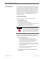
The support they offer includes, but is not limited to:
–
–
–
7000 “C” Frame
Quoting and Managing Product On-site Start-ups.
Quoting and Managing Field Modification projects.
Quoting and Managing Customer in-house and on-site
product training.
7000L-UM302B-EN-P – June 2013
P-4
Preface
7000L-UM302B-EN-P – June 2013
7000 “C” Frame
Table of Contents
Preface
Overview
Who Should Use This Manual ................................................. P-1
What is Not in this Manual ...................................................... P-1
Manual Conventions ................................................................ P-2
General Precautions ................................................................. P-3
Who to Call for Commissioning .............................................. P-3
Chapter 1
Overview of Drive
Introduction .............................................................................. 1-1
Liquid Cooling ......................................................................... 1-1
Topology .................................................................................. 1-3
Rectifier Designs
18-Pulse Rectifier .............................................................. 1-4
Active Front End (AFE Rectifier) ..................................... 1-5
“Direct-to-Drive” Technology ................................................. 1-6
Motor Compatibility ................................................................ 1-7
SGCT Features and Benefits ................................................... 1-9
Specifications ........................................................................... 1-9
Simplified Electrical Drawings
3300/4160 volt ............................................................... 1-12
6000-6600 volt ................................................................ 1-13
Control Overview .................................................................. 1-14
Direct Vector Control ............................................................ 1-14
Control Hardware .................................................................. 1-15
Operator Interface .................................................................. 1-16
Chapter 2
Drive Installation
Safety and Codes ..................................................................... 2-1
Unpacking and Inspection ....................................................... 2-1
Transportation and Handling ................................................... 2-2
Overhead Lifting ............................................................... 2-3
Rod or Pipe Rollers ........................................................... 2-4
Fork Lift Trucks ................................................................ 2-4
Storage ............................................................................... 2-5
Siting of the Drive ................................................................... 2-5
Site Considerations ............................................................ 2-5
Installation ............................................................................... 2-7
Joining Shipping Splits ............................................................ 2-7
Removal of Lifting Angles ..................................................... 2-23
Shock Indication Labels ........................................................ 2-24
Installation of Exhaust Air Hood ........................................... 2-25
Internally Mounted Fans ........................................................ 2-26
Externally Mounted Fans and Fan Hood ............................... 2-27
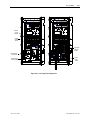
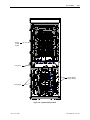
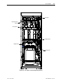
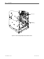
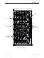
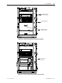
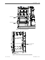
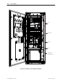
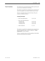
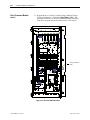
Cabinet Layout and Dimensional Drawings of Drive ............ 2-28
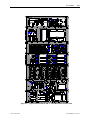
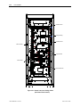
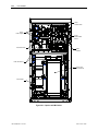
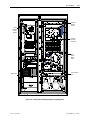
Typical PowerFlex 7000L Drive Structure Layout ............... 2-29
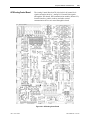
Control/Cabling Cabinet ........................................................ 2-31
Major Components ................................................................ 2-31
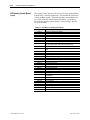
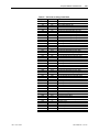
IEC Component and Device Designations ............................ 2-49
7000 “C” Frame - Marine
7000L-UM302B-EN-P – June 2013
ii
Table of Contents
Chapter 2
Drive Installation
(cont.)
Power Wiring Selection ......................................................... 2-49
Cable Insulation .............................................................. 2-50
Wire Group Numbers ...................................................... 2-51
Power Cabling Access ........................................................... 2-52
To Access the Customer Power Cable Terminations ...... 2-52
Power Connections ................................................................ 2-54
Incoming Connections .................................................... 2-54
Liquid Connections ................................................................ 2-55
Liquid-to-Liquid Heat Exchangers .................................. 2-55
Power Control Wiring ............................................................ 2-58
Control Cables ................................................................. 2-58
Encoder Installation Guidelines ...................................... 2-59
Protection from Radiated and Conducted Noise ....... 2-59
Signal Distortion ....................................................... 2-60
Unused Inputs ........................................................... 2-61
Information Regarding Termination of Customer Cables .. 2-62
Grounding Practices ............................................................... 2-63
Grounding Guidelines and Practices for Drive Signal
and Safety Grounds ................................................... 2-64
Grounding Requirements and Grounding Specifications
for Customers and Power Integrators ....................... 2-64
Identification of Types of Electrical Supplies
– Grounded and Ungrounded Systems ..................... 2-65
Ground Bus ..................................................................... 2-65
Interlocking ............................................................................ 2-66
Chapter 3
Operator Interface
Chapter Objectives ................................................................... 3-1
Terminology ............................................................................ 3-1
Overview .................................................................................. 3-3
Keypad .............................................................................. 3-3
Function (Softkeys) Keys ........................................... 3-3
Cursor (Selection) Keys .............................................. 3-4
Data Entry Keys .......................................................... 3-4
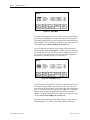
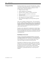
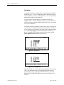
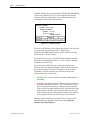
What is a Screen? .............................................................. 3-5
Components ................................................................ 3-5
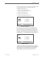
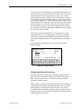
Information Windows ................................................. 3-6
Accessing/Writing to Drive .................................. 3-7
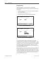
Communication Error ........................................... 3-7
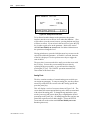
Language Changing ............................................. 3-8
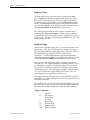
General Operation ....................................................... 3-8
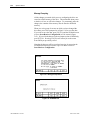
Operator Interface Power-up Sequence ............................. 3-9
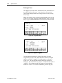
Top Level Menu .............................................................. 3-11
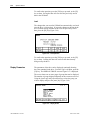
How to:
Obtain Help ..................................................................... 3-12
Related Topics .......................................................... 3-12
Help On Help ............................................................ 3-13
Modify Operator Interface Operation (Utility) ............... 3-14
7000L-UM302B-EN-P – June 2013
7000 “C” Frame - Marine
Table of Contents
Chapter 3
7000 “C” Frame - Marine
Operator Interface
(cont.)
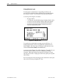
Changing Backlight Delay ........................................ 3-14
Changing Contrast .................................................... 3-15
Setting Time ............................................................. 3-16
Setting Date .............................................................. 3-17
Selecting Meters ....................................................... 3-17
Viewing Revision Levels .......................................... 3-20
Transfer Data in Memory ......................................... 3-21
Picking an Access Level ........................................... 3-21
Select a Parameter ............................................................ 3-22
Via Groups ................................................................ 3-22
Via Name .................................................................. 3-23
Via Code ................................................................... 3-24
Edit Text .......................................................................... 3-26
Configure the Drive ......................................................... 3-28
Enter/Modify an Access Level ................................. 3-28
Drive Setup ............................................................... 3-32
Language Selection ............................................ 3-33
Modify Parameters ............................................. 3-34
Numerical Value ................................................ 3-34
Enumerated Value .............................................. 3-36
Bit Encoded Value ............................................. 3-37
Analog Ports ....................................................... 3-38
Fault Masks ........................................................ 3-39
User Definable External Text ............................. 3-42
PLC .................................................................... 3-43
XIO ..................................................................... 3-45
Message Prompting .................................................. 3-45
Store/Retrieve Configuration (NVRAM) ................. 3-46
Initialize ............................................................. 3-46
Save .................................................................... 3-47
Load ................................................................... 3-47
Display Parameters .......................................................... 3-48
Custom Group ........................................................... 3-50
View Drive Status ........................................................... 3-51
View and Reset Alarms ................................................... 3-51
Help for Alarms ........................................................ 3-52
Request Printouts ............................................................ 3-53
Perform Diagnostic Trending .......................................... 3-54
Assigning a Trace ..................................................... 3-55
Setting the Trigger .................................................... 3-56
Defining Sample Rate and Positioning ..................... 3-57
Starting the Trace ............................................................ 3-58
Flash Memory Transfers ................................................. 3-59
Format Flash Card .................................................... 3-61
View a Directory ....................................................... 3-62
Select a Filename ............................................... 3-62
Enter a Filename ................................................ 3-63
Loading Programs (Firmware) ................................. 3-63
Parameter Transfers .................................................. 3-65
7000L-UM302B-EN-P – June 2013
iii
iv
Table of Contents
Chapter 3
Operator Interface
(cont.)
Chapter 4
Component Definition
and Maintenance
7000L-UM302B-EN-P – June 2013
Upload to Operator Interface ............................. 3-66
Download from Operator Interface .................... 3-66
Upload to Memory Card .................................... 3-66
Download from Memory Card ........................... 3-67
Parameter File Format ................................. 3-67
Loading Language Modules ..................................... 3-68
System Programming ................................................ 3-69
Advanced Screen Operations .......................................... 3-70
Communications Statistics ........................................ 3-70
Protocol Analyzer ..................................................... 3-71
Print Screen ............................................................... 3-72
Memory Dump ......................................................... 3-72
Database Download .................................................. 3-74
Operator Interface Menu Hierarchy Chart
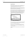
What does it show? ......................................................... 3-75
How do you read it? ........................................................ 3-75
Example ........................................................................... 3-76
PowerFlex 7000 Terminal Menu Tree ............................ 3-77
PCMCIA Memory Card Installation Data
Description ...................................................................... 3-79
Installing the Memory Card ............................................ 3-79
Control/Cabling Cabinet Components ..................................... 4-1
Voltage-Sensing Assembly ...................................................... 4-4
Voltage-Sensing Circuit Board Assembly Replacement ........... 4-5
Input Transient Protection ....................................................... 4-6
Transient Suppression Network (TSN) .................................... 4-6
Description ........................................................................ 4-6
MOV Suppressor ............................................................... 4-6
MOV Fuse ......................................................................... 4-7
Simplified Wiring Diagram ............................................... 4-9
Transient Suppression Network Fuse Replacement .............. 4-19
Metal-Oxide Varistor Replacement ....................................... 4-10
Surge Arresters ...................................................................... 4-10
Description ...................................................................... 4-10
Operation ......................................................................... 4-11
Surge Arrester Replacement ............................................ 4-12
Field Test and Care ......................................................... 4-13
Output Grounding Network Capacitor Replacement ............. 4-13
Ground Filter Replacement .................................................... 4-15
Hall Effect Sensor Replacement ............................................ 4-17
Current Transformer (CT) Replacement ................................ 4-18
Filter Capacitor Cabinet ......................................................... 4-19
Filter Capacitors .............................................................. 4-19
Filter Capacitor Replacement .......................................... 4-20
Testing Filter Capacitors ................................................ 4-21
Converter Cabinet Components ............................................. 4-23
Converter Cabinet .................................................................. 4-24
7000 “C” Frame - Marine
Table of Contents
Chapter 4
Component Definition
and Maintenance
(cont.)
7000 “C” Frame - Marine
PowerCage™ ......................................................................... 4-24
SGCT and Snubber Circuit ................................................... 4-27
Uniform Clamping Pressure .................................................. 4-27
Checking Clamping Pressure ................................................ 4-28
Clamping Pressure Adjustment ...................................... 4-28
Temperature Sensing ............................................................. 4-29
Symmetrical Gate Commutated Thyristor Replacement ....... 4-30
Silicon Controlled Rectifier and SCR Self-Powered
Gate Driver Board Replacement ..................................... 4-33
Detachment of Coolant System from PowerCage Modules ....... 4-36
Reconnecting the Coolant System to PowerCage Module ... 4-38
Chill Block Removal and Replacement ................................. 4-41
Instructions for Inserting Chill Block Assembly ............. 4-42
PowerCage Removal and Replacement ................................. 4-43
Snubber Resistors .................................................................. 4-44
Testing Snubber Resistors ............................................... 4-45
Sharing Resistors ................................................................... 4-45
Testing Sharing Resistors ................................................ 4-46
SGCT PowerCages ................................................... 4-46
SCR PowerCages ...................................................... 4-47
Snubber and Sharing Resistor Replacement .......................... 4-47
Self-Powered Gate Driver Board – SPGDB .......................... 4-49
Description ...................................................................... 4-49
Board Calibration ............................................................ 4-49
Test Points Description ................................................... 4-50
Terminal/Connections Description ................................. 4-51
Testing Procedure for SCR Self-Powered Gate Driver Board ... 4-52
Equipment Needed .......................................................... 4-52
Procedure ......................................................................... 4-52
Fiber Optic Cabling ............................................................... 4-56
DC Link and Control Power Section ..................................... 4-57
DC Link Reactor ............................................................. 4-58
Control Power Components ................................................... 4-59
Ride-Through .................................................................. 4-59
AC/DC Power Supply ............................................................ 4-62
Description ...................................................................... 4-62
Location ........................................................................... 4-63
Terminal/Connections Description ................................. 4-64
Replacement Procedure ................................................... 4-65
UPS Option ............................................................................ 4-66
UPS Replacement Procedure .......................................... 4-67
Cooling System ...................................................................... 4-68
Cooling Circuit ................................................................ 4-69
Chill Blocks ..................................................................... 4-69
Coolant Pumps ................................................................ 4-69
Pump Maintenance and Replacement .................................... 4-70
Pump Seal Replacement .................................................. 4-70
Pump Replacement .......................................................... 4-71
Piping, Tubing and Connectors ....................................... 4-71
Non-Return Valves .......................................................... 4-72
7000L-UM302B-EN-P – June 2013
v
vi
Table of Contents
Chapter 4
Component Definition
and Maintenance
(cont.)
7000L-UM302B-EN-P – June 2013
Pressure Indicator ............................................................ 4-72
Pressure Switch ............................................................... 4-72
Thermostatic Valve ......................................................... 4-73
Thermostatic Valve Replacement ................................... 4-74
Repair Instructions – Element Testing ............................ 4-75
Element Replacing .......................................................... 4-75
Heat Exchanger ............................................................... 4-76
Temperature Gauge ......................................................... 4-77
Fluid Conductivity .......................................................... 4-77
Temperature Sensor ........................................................ 4-77
De-ionizing Cartridge and Mesh Filter ........................... 4-78
Replacing the Mesh Filters .............................................. 4-79
Reservoir Circuit ............................................................. 4-79
Fluid Top-up .................................................................... 4-80
Strainers ........................................................................... 4-81
Coolant ............................................................................ 4-82
Leakage Checks .............................................................. 4-84
System Drain ................................................................... 4-84
Low Voltage Control Section ................................................ 4-85
DC/DC Power Supply ............................................................ 4-86
Description ...................................................................... 4-86
Terminal/Connections Descriptions ................................ 4-87
Replacement Procedure for DC/DC Power Supply ........ 4-88
Printed Circuit Board Replacement ....................................... 4-89
IO Connectors on Control Boards ......................................... 4-90
Drive Processor Module ........................................................ 4-91
Drive Processor Module Replacement ............................ 4-92
Instructions to Replace the Drive Processor Module ..... 4-92
ACB Analog Control Board .................................................. 4-95
LEDs ............................................................................... 4-98
Interface Module (IFM) .................................................. 4-99
Analog Inputs and Outputs .............................................. 4-99
Current Loop Transmitter .................................................... 4-100
Isolated Process Receiver .............................................. 4-101
Non-Isolated Process Outputs ....................................... 4-102
Auxiliary +24V Power Supply ...................................... 4-102
ACB Analog Control Board Replacement .................... 4-103
Tachometer Feedback Board ............................................... 4-104
Encoder Options ............................................................ 4-104
Quadrature Encoder Operation ...................................... 4-108
Positional Encoder Operations ...................................... 4-109
Positional Encoder Guidelines ...................................... 4-110
External Input/Output Boards .............................................. 4-111
External Input/Output Board Replacement ................... 4-113
Optical Interface Boards (OIB) ............................................ 4-114
Optical Interface Board Replacement ........................... 4-115
Optical Interface Base Board (OIBB) .................................. 4-117
Optical Interface Base Board Test Points ..................... 4-118
Downloading Firmware ....................................................... 4-119
7000 “C” Frame - Marine
Table of Contents
Chapter 4
Component Definition
and Maintenance
(cont.)
Appendix A Catalog Number
Explanation for
PowerFlex 7000
MV Drives
7000 “C” Frame - Marine
Introduction ................................................................... 4-119
Overview ....................................................................... 4-119
Preparation for Downloading Firmware .............................. 4-120
PF7000 in Download Mode .......................................... 4-122
Reloading the Parameters .................................................... 4-125
Setting Elapsed Time .......................................................... 4-126
Download the Terminal Firmware ...................................... 4-126
Setting up Diagnostic Trending .......................................... 4-129
Diagnostic Setup .......................................................... 4-129
Setting up the Trend ..................................................... 4-130
Printing (Uploading) Data from the Drive .......................... 4-136
Overview ...................................................................... 4-136
Required ....................................................................... 4-136
Method ......................................................................... 4-137
Printing (Uploading) Control Data ..................................... 4-143
Overview ...................................................................... 4-143
Required ....................................................................... 4-143
Method ......................................................................... 4-144
Environmental Considerations ............................................. 4-150
Hazardous Materials .................................................. 4-150
Disposal ..................................................................... 4-151
Preventive Maintenance Check List .................................... 4-152
Operational Maintenance ..................................................... 4-152
Annual Maintenance ............................................................ 4-154
Initial Information Gathering ..................................... 4-154
Physical Checks (NO MV and NO Control Power) ... 4-154
Control Power Checks (No Medium Voltage) ........... 4-156
Final Power Checks before Restarting ....................... 4-156
Additional Tasks During Preventive Maintenance .... 4-157
Final Reporting .......................................................... 4-157
Time Estimations ......................................................... 4-158
Tool/Parts/Information Requirements .......................... 4-159
Catalog Number Explanation .................................................. A-1
Service Duty Rating, Continuous Current Rating and
Altitude Rating Code ........................................................ A-2
Nominal Line Voltage, Control Voltage, System Frequency ... A-2
PowerFlex 7000 Drive Selection Explanation ........................ A-3
When is a Tachometer Required? ........................................... A-4
PowerFlex 7000 Drive Performance (Torque Capabilities) ... A-5
Glossary of Terms ................................................................... A-5
Typical Application Load Torque Profiles ............................. A-6
7000L-UM302B-EN-P – June 2013
vii
viii
Table of Contents
Appendix B Torque Requirements Torque Requirements for Threaded Fasteners ........................ B-1
Appendix C Meggering
Drive Meggering ..................................................................... C-1
Meggering the PowerFlex 7000 .............................................. C-1
Equipment Required ......................................................... C-2
Procedure .......................................................................... C-2
Appendix D Preventative
Powerflex 7000 Maintenance Schedule .................................. D-1
Maintenance
Schedule
7000L-UM302B-EN-P – June 2013
7000 “C” Frame - Marine
Chapter
1
Overview of Drive
Introduction
The PowerFlex® 7000 represents the third generation of medium
voltage drives at Rockwell Automation. The PowerFlex 7000
medium voltage AC drive is part of the PowerFlex family of AC
drive products. The Allen-Bradley PowerFlex® family of Drives
incorporates leading-edge technology, embedded communications,
and significant commonality across multiple platforms, networks,
operator interface programming and hardware. Designed for end
users, solution providers and OEMs, PowerFlex 7000 liquid-cooled
drives meet applications ranging from 3,000 to 9,000 horsepower
(2240-6715 kW).
The PowerFlex 7000L is a general purpose stand alone medium
voltage drive that controls speed, torque, direction, starting, and
stopping of standard asynchronous or synchronous AC motors. It is
intended for use on a host of standard and specialty applications such
as fans, pumps, compressors, mixers, conveyors, kilns, fan-pumps,
and test stands. Primary industries for these applications include
petrochemical, cement, mining and metals, forest products, power
generation, and water / waste water.
The PowerFlex 7000L is a global product that adheres to the most
common standards from NEC, IEC, NEMA, UL, and CSA. It is
available with the world‟s most common supply voltages at medium
voltage, from 2400-6600 volts.
The design focus is on high reliability, ease of use, and lower total
cost of ownership.
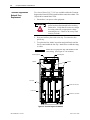
Liquid Cooling
For 2400V and 3300V designs, contact factory.
The PowerFlex 7000L “C” Frame liquid-cooled drive utilizes a
closed loop system to cool the converter main power components
and the integral DC link inductor.
The Main Benefits of Liquid Cooling Include:
7000 “C” Frame - Marine
Smaller drive dimension compared to air-cooled drives of similar
rating
Higher power rating capability
Quiet operation in control room
Low loss rejection to the control room reduces air conditioner
loading
Majority of losses rejected outside the control room via a liquidto-air or liquid-to-liquid type heat exchanger
7000L-UM302B-EN-P – June 2013
1-2
Overview of Drive
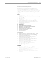
The Main Benefits of the 7000L “C” Frame Liquid-cooled Drive
Include:
7000L-UM302B-EN-P – June 2013
Completely integrated MV drive package reduces customer
installation costs and start-up time.
Higher power rating capability (up to 9000 hp / 6715 kW)
18 Pulse and AFE rectifiers for low harmonic solutions that meet
IEEE 519-1992 Harmonic Guidelines
Motor friendly current and voltage output waveforms for use
with standard new and existing motors
– Inverter duty motors not required
– Motor temperature derating not required
– No additional dv/dt or peak voltage stress to motor insulation
system
– Tested up to 15 kilometers (9.3 miles) cable distance
between drive and motor
Spacious cable termination cabinet for ease of use by installation
contractor
Cable termination stabs accommodate:
– 3 cables in / 3 cables out (Direct-to-Drive or AFE rectifier)
– 9 cables in / 3 cables out (18 pulse)
– Top or bottom entry and exit of line and load cables
90% of drive losses are rejected outside the control room
Integral liquid-cooled DC link inductor reduces overall
dimension and eliminates external interwiring.
Integral pumping panel includes:
– Line supply c/w disconnect and fusing
– Closed loop coolant system
– Iron and chloride free liquid ethyl-glycol / deionized water
mixture
– Low conductivity coolant (1-2 micro-Siemens / cm3)
– Isolated from medium voltage
– Fully serviceable low voltage compartment isolated from
medium voltage power
– Monitors coolant temperature, flow, level, conductivity, and
pressure
– Redundant pumping system (optional)
– Automatic pump change over on pump failure
– 1/2 turn valves with quick disconnect couplers for pump
replacement when drive is operating
– Full drip tray to contain any spilled coolant
– Drain and fill pump for convenient filling
– Industrial schedule 80 CPVC piping for pump panel, headers
and manifolds (no condensation possibility)
– Control hardware for cycling of main / redundant cooling
pumps and heat exchanger fans
7000 “C” Frame - Marine
Overview of Drive
Topology
1-3
“Plug and play” Power Cage concept
– Central location for easy access to all main power
components
– Common modular design for rectifier / inverter
– Same concept as air-cooled drive for front access, easy
component replacement, and no special tools
– 5-10 minutes to replace main power devices
– No need to remove any cooling lines for device replacement
– Reduced manufacturing time for faster delivery and lower cost
Keyed mechanical interlock
– Interlocked with main disconnect means to prevent unsafe
access to medium voltage section
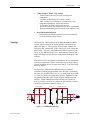
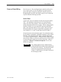
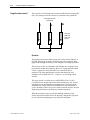
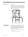
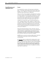
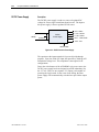
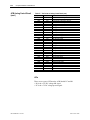
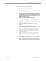
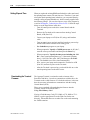
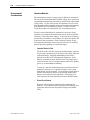
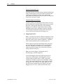
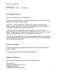
The PowerFlex 7000L utilizes a Pulse Width Modulated (PWM) –
Current Source Inverter (CSI) for the machine side converter as
shown in Figure 1.1. This topology offers a simple, reliable, cost
effective power structure that is easy to apply to a wide voltage and
power range. The power semiconductor switches used are easy-toseries for any medium voltage level. Semiconductor fuses are not
required for the power structure due to the current limiting DC link
inductor.
With 6500 volt PIV rated power semiconductor devices, the number
of inverter components is kept to a minimum. For example, only six
inverter switching devices are required at 2400V, 12 at 3300-4160V,
and 18 at 6600V.
The PowerFlex 7000L has the additional benefit of inherent
regenerative braking for applications where the load is overhauling
the motor (i.e. downhill conveyors, etc.), or where high inertia loads
(i.e. fans, etc.) need to be slowed down quickly. Symmetrical Gate
Commutated Thyristors (SGCTs) are used for machine converter
switches. Silicon-controlled rectifiers (SCRs) (for 18 pulse) or
SGCTs (for AFE rectifiers) are used for the line converter switches.
An AFE configuration is shown in Figure 1.1.
LINE C ONVERTER
MACHINE C ONVE RTER
DC LINK
L+
M+
SGCTs
SGCTs
2U (X1)
U (T1)
2V (X2)
V (T2)
2W (X3)
W (T3)
L-
M-
Figure 1.1 – AFE Rectifier (4160 Volt)
7000 “C” Frame - Marine
7000L-UM302B-EN-P – June 2013
1-4
Overview of Drive
Rectifier Designs
There are two offered designs for the rectifier of the PowerFlex 7000L
drive.
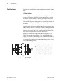
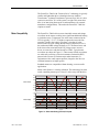
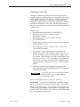
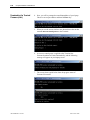
18-Pulse Rectifier
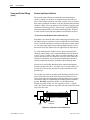
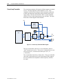
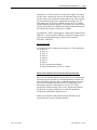
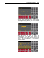
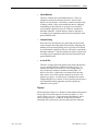
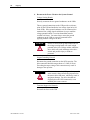
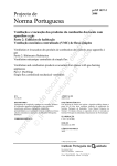
An 18-pulse phase controlled rectifier is shown in Figure 1.2. In an
18-pulse configuration, the IEEE 519-1992 requirements are met in
the majority of cases without the need for passive filters; however, a
multi-winding isolation transformer is required to mitigate the low
order harmonics by phase shifting principles. The 18-pulse solution is
superior to 6- or 12-pulse offerings in terms of lowering line side
harmonics.
Isolation transformers are available in indoor dry type, cast coil, and
outdoor oil-filled designs for maximum flexibility in dealing with floor
space, installation costs, and control room air conditioner loading.
(Refer to Specification 80001-005, Rectifier Duty Transformers, for
more details on transformer requirements and features.)
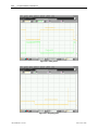
Sample line current and voltage are also shown in Figure 1.2. The
THD of line current is approximately 5.6%, while the THD of line
voltage (line-to-line) is approximately 2.0%. (THD of line voltage is
a function of system impedance.) The 18-pulse rectifier consists of
one master bridge and two slave bridges and will always have a total
of 18 SCR switching devices.
a)
b)
Figure 1.2 – 18-pulse Rectifier and its input waveforms
a) Line current
b) Line-to-line voltage at PCC
7000L-UM302B-EN-P – June 2013
7000 “C” Frame - Marine
Overview of Drive
1-5
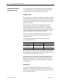
Active Front End (AFE Rectifier)
An active front end (AFE rectifier) suitable for the PowerFlex 7000L
topology is also commonly called a PWM rectifier. This is particularly
attractive since it does not require an isolation transformer to meet
IEEE 519-1992. Most available technologies in today‟s MV market
require a multi-winding transformer to mitigate the unwanted
harmonics by phase shifting the transformer secondary windings.
Depending on the topology, the transformer can have up to 15 sets of
secondary windings. Elimination of the isolation transformer reduces
capital and installation costs, saves on valuable floor space, and
increases overall system efficiency.
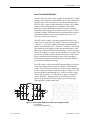
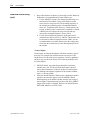
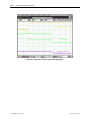
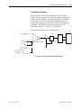
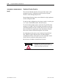
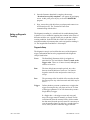
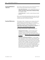
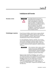
The AFE rectifier requires a switching pattern that complies with
similar rules as the inverter. The pattern, used for the example shown
in Figure 1.3, is a 42-pulse selective harmonic elimination (SHE)
pattern, which eliminates the 5th, 7th and 11th harmonics. The integral
input capacitors are designed to reduce the current harmonics of the
higher order. The filter transfer function technique is used to place the
filter break frequency in a region where no harmonics are present. This
prevents the excitation of system harmonic frequencies. Other factors
that are considered when designing the filter are the input power
factor and the requirement on Total Harmonic Distortion (THD) of
input current and voltage waveforms.
The AFE rectifier is ideal when a distribution transformer is required
to step down the distribution voltage to match the VFD and motor
voltage. The rectifier input current, the rectifier terminal voltage and
the line current and voltage waveforms are shown in Figure 1.3. The
line current THD is approximately 4.5%, while line-to-line voltage
THD is approximately 1.5%. (THD of line voltage is a function of
system impedance.) Input power factor with the AFE rectifier is
equal to or greater than 0.98 for the typical speed and load range
when applied to variable torque loads.
a)
Figure 1.3 – Active rectifier (PWM) and its input current/voltage waveforms
a) Line current
b) Line-to-line voltage at PCC b)
7000 “C” Frame - Marine
7000L-UM302B-EN-P – June 2013
1-6
Overview of Drive
“Direct-to-Drive” Technology
The PowerFlex 7000L with “Direct-to-Drive” technology allows you to:
connect supply power directly to the drive without an Isolation
Transformer
connect a new or existing motor directly to the drive without
extra motor filtering.
Most Medium Voltage Drive Manufacturers use multi-winding
isolation transformers to mitigate unwanted harmonics by phase
shifting the transformer secondary windings. Depending on the
topology, the transformer can have up to 15 sets of secondary
windings. The disadvantages to this method are the high degree of
drive and transformer complexity, a very high component count and
many interconnecting cables and connection points. This leads to
much higher maintenance requirements and lower reliability.
Manufacturers also use isolation transformers to protect motors from
Common Mode Voltage stress. When transformers are used they
allow the motor neutral point to be connected to ground, but with this
method, the common mode voltage that would otherwise be impressed
on the motor is impressed on the transformer. The disadvantage to
this method is that increased transformer insulation and increased
cable insulation is required between the transformer and the drive so
it can withstand the common mode voltage stress.
Rather than use an Isolation Transformer, the “Direct-to-Drive”
Active Front End uses the semiconductor switching pattern to reduce
line current harmonics to levels that comply to the world‟s most
accepted harmonic standards. The Active Front End is the best
method of harmonic cancellation because it does not suffer from
complexity and high component count like multi-pulse drive
topologies do.
“Direct-to-Drive” technology produces virtually no common mode
voltage so it is suitable for new or existing motors and imposes no
stress on the drive input. The advantage of “Direct-to-Drive”
technology over an Isolation Transformer is that no extra insulation
is required in the motor, in the motor cables or in the line cables.
In addition to mitigating Common Mode Voltage, “Direct-to-Drive”
technology mitigates dv/dt or Reflected Wave Voltage Stress on motors.
The simplicity of its design results in a lower initial capital
investment, lower operating cost, lower installation cost and lower
maintenance cost relative to drives that require isolation
transformers.
7000L-UM302B-EN-P – June 2013
7000 “C” Frame - Marine
Overview of Drive
1-7
The PowerFlex 7000L with “Direct-to-Drive” technology is typically
smaller and lighter than drive technologies that use Isolation
Transformers. Isolation Transformers represent 30 to 50% of a drive
system size and 50 to 70% of the system‟s weight. This means that
there is no interwiring between drive and transformer (for external
transformer configurations). This makes the PowerFlex 7000L the
simplest to install.
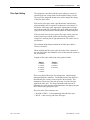
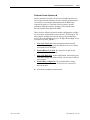
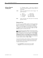
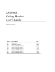
Motor Compatibility
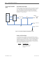
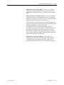
The PowerFlex 7000L achieves near sinusoidal current and voltage
waveforms to the motor, resulting in no significant additional heating
or insulation stress. Temperature rise in the motor connected to the
VFD is typically 3 °C (5.5 °F) higher compared to across the line
operation. Dv/dt in the voltage waveform is less than 10 volts /
microsecond. The peak voltage that the motor insulation will see is
the rated motor RMS voltage divided by 0.707. Reflected wave and
dv/dt issues often associated with VSI (voltage source inverter)
drives are a non-issue with the PowerFlex 7000L. Typical motor
waveforms are shown in Figure 1.5. These motor friendly waveforms
are achieved by utilizing a selective harmonic elimination (SHE)
pattern in the inverter to eliminate major order harmonics, in
conjunction with a small output capacitor (integral to the drive) to
eliminate harmonics at higher speeds.
Standard motors are compatible without derating, even on retrofit
applications.
Motor cable distance is virtually unlimited. This technology has been
tested, controlling motors up to 15 km (9.3 miles) away from the drive.
Arms
300.00
200.00
100.00
Motor current
0.00
-100.00
-200.00
-300.00
Vrms
10.00K
7.50K
5.00K
Motor voltage
2.50K
0.00K
-2.50K
-5.00K
-7.50K
-10.00K
100.00
110.00
120.00
TIME (ms)
130.00
140.00
150.00
Figure 1.4 – Motor waveforms @ full load, full speed
7000 “C” Frame - Marine
7000L-UM302B-EN-P – June 2013
1-8
Overview of Drive
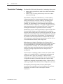
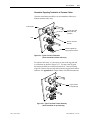
SGCT Features and Benefits
An SGCT is a Symmetrical Gate Commutated Thyristor with an
integrated gate drive. Positioning the gate drive close to the SGCT as
shown in Figure 1.5, creates a low inductance path that provides
more efficient and uniform gating of the device. As a result, the
device is better suited than a conventional GTO to handle the
fluctuating levels of voltage and current while it is switching on and
off during gating.
An SGCT has similar characteristics to an IGCT (used on some VSI
drives), including low conduction and switching losses, low failure
rate, and double sided cooling for low thermal stress. However, the
SGCT achieves voltage blocking capability in both forward and
reverse directions up to 6500 volts by a NPT (Non-Punch-Through)
structure and nearly symmetrical pnp transistor in the wafer, while
the current is unidirectional. Unlike many VSI topologies that use
IGBTs, the semiconductors used in the PowerFlex 7000L feature a
non-rupture, non-arc failure mode. In the unlikely event of a device
failure, the fault would be contained within the device.
Implementing SGCTs in the PowerFlex 7000L „B‟ Frame results in
significant advantages including:
1. Simplification of the snubber design and a reduction in the size
of the snubber capacitor by a factor of 10.
2. Operation at a higher switching frequency (420-540 Hz), hence
reducing the size of passive components (DC link inductor and
motor filter cap) by 50%.
3. Improving performance of the drive.
4. Reduction of component count, hence improving reliability, cost,
and size of the drive.
5. Fail safe failure mode (non-rupture).
Figure 1.5 – SGCT with integrated gate drive (left) and unit cell structure (right)
7000L-UM302B-EN-P – June 2013
7000 “C” Frame - Marine
Overview of Drive
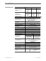
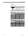
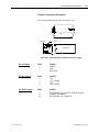
Specifications
Description
Power Rating (Liquid Cooled)
Motor Type
Input Voltage Rating
Input Voltage Tolerance
Voltage Sag
Control Power Loss Ride-Through
Input Protection
Input Frequency
Input Short-circuit Current Withstand
3300 V – 6000 V
Basic Impulse Level
Power Bus Design
Ground Bus
Customer Control Wireway
Input Power Circuit Protection
Input Impedance Device
Output Voltage
Inverter Design
Inverter Switch
Inverter Switch Failure Mode
Inverter Switch Failure Rate (FIT)
Inverter Switch Cooling
Inverter Switching Frequency
Number of Inverter SGCTs
SGCT PIV Rating
(Peak Inverse Voltage)
Rectifier Designs
Rectifier Switch
Rectifier Switch Failure Mode
Rectifier Switch Failure Rate (FIT)
Rectifier Switch Cooling
7000 “C” Frame - Marine
1-9
Specifications
3000 – 9000 hp
2240 – 6715 kW
Induction or Synchronous
2400V, 3300V, 4160V, 6600V
± 10% of Nominal
-30%
5 Cycles (Std)
Metal Oxide Varistor (MOV) – 18P
Surge Arrestors (AFE/D2D)
50/60 Hz, +/- 5%
5 Cycle
25 MVA RMS SYM
50 kV (0 – 1000 m)
Copper – Tin plated
Copper – Tin plated 6 x 51 mm (¼ x 2 in.)
Separate and Isolated
Vacuum Contactor with Fused Isolating Switch
or Circuit Breaker
Isolation Transformer or AC Line Reactor
0 – 2300 V
0 – 3300 V
0 – 4160 V
0 – 6600 V
PWM
Symmetrical Gate Commutated Thyristor (SGCT)
Non-rupture, Non-arc
100 per 1 Billion Hours Operation
Double Sided, Low Thermal Stress
420-540 Hz
Voltage
SGCTs (per phase)
2400 V
2
3300 V
4
4160 V
4
6600 V
6
Voltage
PIV
2400 V
6500 V
3300 V
6500 V
4160 V
6500 V
6600 V
6500 V
AFE (Active Front End), 18 Pulse
Direct-to-Drive
SCR (18 Pulse)
SGCT (AFE, Direct-to-Drive)
Non-rupture, Non-arc
50 (SCR) 100 (SGCT) per 1 Billion Hours Operation
Double Sided, Low Thermal Stress
NEMA:
IEC:
For 2400V and 3300V configurations, contact factory.
Voltage Sag tolerance is reduced to -25% when control power is supplied from medium voltage via CPT.
MOVs are used for 18 Pulse. Surge Arrestors are used for AFE/D2D configurations.
Short-circuit fault rating based on input protection device (contactor or circuit breaker).
BIL rating based on altitudes < 1000 m (3,300 ft.) Refer to factory for derating on altitudes >1000 m.
Optional
7000L-UM302B-EN-P – June 2013
1-10
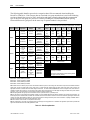
Overview of Drive
Specifications (cont.)
Description
Number of Rectifier Devices
per phase
SCR PIV Rating
(Peak Inverse Voltage)
Output Waveform to Motor
Medium Voltage Isolation
Modulation Techniques
Control Method
Tuning Method
Speed Regulator Bandwidth
Torque Regulator Bandwidth
Speed Regulation
Acceleration/Deceleration Range
Acceleration/Deceleration Ramp Rates
S Ramp Rate
Critical Speed Avoidance
Stall Protection
Load Loss Detection
Control Mode
Current Limit
Output Frequency Range
Service Duty Rating
Overload Rating
Typical VFD Efficiency
Input Power Factor
IEEE 519 Harmonic Guidelines
VFD Noise Level
Regenerative Braking Capability
Flying Start Capability
Operator Interface
Languages
7000L-UM302B-EN-P – June 2013
Specifications
18-Pulse
AFE / D2D
6
2
6
4
6
4
6
6
18-Pulse
AFE / D2D
4500 V
6500 V
4500 V
6500 V
4500 V
6500 V
6500 V
6500 V
Sinusoidal Current / Voltage
Fiber Optic
SHE (Selective Harmonic Elimination)
Synchronous Trapezoidal PWM
Asynchronous and Synchronous SVM
(Space Vector Modulation)
Digital Sensorless Direct Vector
Full Vector Control with Tach Feedback (Optional)
Auto Tuning via Setup Wizard
5-25 Radians / Second
15-50 Radians / Second
0.1% without Tachometer Feedback
0.01-0.02% with Tachometer Feedback
Independent Accel/Decel – 4 x 1200 sec.
4 x Independent Accel/Decel
Independent Accel/Decel – 2 x 1200 sec.
3 x Independent with Adjustable Bandwidth
Delay / Speed
Adjustable level, delay, speed set points
Speed or Torque
Adjustable in Motoring and Regenerative
0.2-85 Hz
Normal Duty
Heavy Duty
150% Overload for
110% Overload for
1 minute every 10 minutes
1 minute every 10 minutes
(Constant or Variable
(Variable Torque Load)
Torque Load)
> 98% ( 18 Pulse)
> 97.5% (AFE)
Contact Factory for Guaranteed Efficiency
of Specific Drive Rating
AFE Rectifier
0.98 minimum, 30 – 100% Load
IEEE 519 – 1992 Compliant
< 85 dB(A) per OSHA standard 3074
Inherent – No Additional Hardware or Software Required
Yes – Able to Start into and Control a Spinning Load in
Forward or Reverse Direction
40-character, 16-line formatted text
English
German
French
Chinese (Mandarin)
Spanish
Portuguese
Italian
Voltage
2400 V
3300 V
4160 V
6600 V
Voltage
2400 V
3300 V
4160 V
6600 V
7000 “C” Frame - Marine
Overview of Drive
Description
Control Power
External I/O
External Input Ratings
External Output Ratings
Analog Inputs
Analog Resolution
Analog Outputs
Communication Interface
Scan Time
Communications Protocols
(Optional)
Enclosure
Lifting Device
Mounting Arrangement
Structure Finish
Interlocking
Corrosion Protection
Fiber Optic Interface
Door Filter
Door Filter Blockage
Coolant
Coolant Conductivity
Heat Exchangers
Ambient Temperature
Storage and Transportation
Temperature Range
Relative Humidity
Altitude (Standard)
Altitude (Optional)
Seismic (UBC Rating)
Standards
7000 “C” Frame - Marine
1-11
Specifications
220/240 V or 110/120 V, 1 phase – 50/60 Hz (20 Amp)
16 Digital Inputs, 16 Digital Outputs
50/60 Hz AC or DC
120-240 V – 1 mA
50-60 Hz AC or DC
30-260 V – 1 amp
(3) Isolated, 4-20mA or 0-10 V
• Analog input 12 Bit (4-20 mA)
• Analog input 13 Bit (0-10V)
• (1) Isolated, 4-20 mA
• (8) Non-isolated, 0-10 V
DPI
Internal DPI – 2 ms min., 4 ms max.
R I/O
Lon Works
DeviceNet
Can Open
Ethernet
RS485 HVAC
Profibus
RS485 DF1
Modbus
RS232 DF1
Interbus
USB
NEMA 1 (IP21), NEMA 12 (IP42)
Standard / Removable
Mounting Sill Channels
Epoxy Powder – Paint
Exterior Sandtex Light Grey (RAL 7038) – Black (RAL 8022)
Internal – Control Sub Plates – High Gloss White (RAL 9003)
Key provision for customer input Disconnecting Device
Unpainted Parts (Zinc Plates / Bronze Chromate)
Rectifier – Inverter – Cabinet (Warning/Trip)
Painted Diffuser with Matted Filter Media
Air Flow Restriction Trip/Warning
Iron and chlorine free ethylene glycol
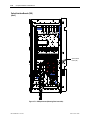
mixed with de-ionized water
1-2 micro-Siemens/CM
Liquid-to-Air, Liquid-to-Liquid
0° to 45°C (32°F to 113°F)
-40°C to 70°C (-40°F to 185°F)
95% Non-Condensing
0 to 3300 ft. (0 to 1000 m)
0 to 16400 ft. (1001 to 5000 m)
1, 2, 3, 4
NEMA, IEC, CSA, UL, ANSI, IEEE
7000L-UM302B-EN-P – June 2013
1-12
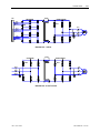
Overview of Drive
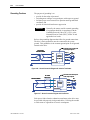
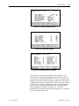
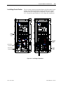
Simplified Electrical Drawings
DC LINK
L+
M+
LINE CONVERTER
ISTX
4U (Z1)
4V (Z2)
4W (Z3)
MACHINE CONVERTER
SGCTs
SCRs
U (T1)
3U (Y1)
3V (Y2)
3W (Y3)
V (T2)
W (T3)
2U (X1)
2V (X2)
2W (X3)
L-
M-
3300 / 4160 Volt – 18 Pulse
LINE CONVERTER
L+
DC LINK
M+
SGCTs
MACHINE CONVERTER
SGCTs
2U (X1)
U (T1)
2V (X2)
V (T2)
2W (X3)
W (T3)
L-
M-
3300 / 4160 Volt – Active Front End
7000L-UM302B-EN-P – June 2013
7000 “C” Frame - Marine
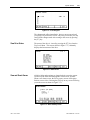
Overview of Drive
ISTX
LINE CONVERTER
4U (Z1)
4V (Z2)
4W (Z3)
L+
DC LINK
M+
1-13
MACHINE CONVERTER
SGCTs
SCRs
U (T1)
3U (Y1)
3V (Y2)
3W (Y3)
V (T2)
W (T3)
2U (X1)
2V (X2)
2W (X3)
L-
M-
6000-6600 Volt – 18 Pulse
DC LINK
LINE CONVERTER
L+
M+
SGCTs
MACHINE CONVERTER
SGCTs
2U (X1)
U (T1)
2V (X2)
V (T2)
2W (X3)
W (T3)
L-
M-
6000-6600 Volt – Active Front End
7000 “C” Frame - Marine
7000L-UM302B-EN-P – June 2013
1-14
Overview of Drive
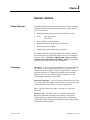
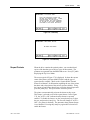
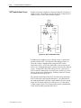
Control Overview
Line Converter
Machine Converter
DC Link
Inductor
Faults
Line
Synch
Current
Control
Machine
gating and
diagnostic
feedback
Machine
Side
Control
Idc ref.
Ref.
Current and
phase shift
calculator
Machine
Converter
Feedback
Machine
Converter
Protection
(HW)
Faults
Mag.Current
command
Machine
Converter
Protection
(SW)
Tach. Feedback
Line
Converter
Protection
Line
Side
Control
Motor
Faults
Line gating
and
diagnostic
feedback
Sync. angle
Line
Converter
Protection
(HW)
Machine converter
firing angle
Line
Converter
Feedback
Line converter firing angle
Motor fil. Cap.
Motor
Model
Flux
Flux
Control
Speed Feedback
Torque
Speed
Control
Speed
Command
Speed Ref.
Skip Speed
and Speed
Ramp
Torque current command
Synch.
Transfer
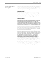
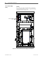
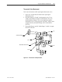
Figure 1.6 – PowerFlex 7000L „C‟ Frame Function Block Diagram
Direct Vector Control
The method of control in the PowerFlex 7000 “C” Frame medium
voltage AC drive is called sensorless direct vector control, meaning
that the stator current is divided into torque producing and flux
producing components, allowing the motor torque to be changed
quickly without affecting motor flux. This method of control is used
without tachometer feedback for applications requiring continuous
operation above 6 Hertz and less than 100% starting torque.
Full vector control can also be achieved with tachometer feedback
for applications requiring continuous operation down to 0.2 Hertz
with up to 150% starting torque. Vector control offers superior
performance over volts/hertz type drives. The speed bandwidth
range is 5-25 radians per second, while the torque bandwidth range is
15-50 radians per second.
7000L-UM302B-EN-P – June 2013
7000 “C” Frame - Marine
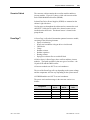
Overview of Drive
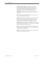
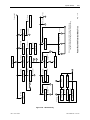
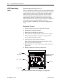
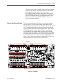
Control Hardware
1-15
The control hardware includes a processor board (DPM) with an
interface to six fiber optic boards (depending on the voltage and
number of switching devices) via OIBB, an analog conditioning
board (ACB) and an external IO board (XIO). The control hardware
is used for rectifier and inverter, induction or synchronous drive
control and the two rectifier types (18-pulse or Active Front End).
The DPM features two floating point DSPs (Digital Signal
Processor) and a FPGA (Field Programmable Gate Array) for
advanced functions such as gating and diagnostics, fault handling
and drive synchronization control.
OIBB
OIBB
OIB
OIB
OIB
OIB
OIB
OIB
ACB
DPM
ACB
DPM
OIBB
XIO
OIB
–
–
–
–
–
Analog Conditioning Board
Drive Processor Module
Optical Interface Base Board
External Input/Output
Optical Interface Board
XIO
Figure 1.7 – Control Hardware Layout
for PowerFlex 7000 “C” Frame
7000 “C” Frame - Marine
7000L-UM302B-EN-P – June 2013
1-16
Overview of Drive
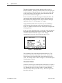
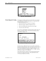
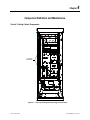
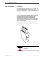
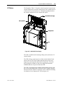
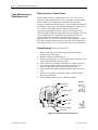
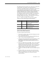
Operator Interface
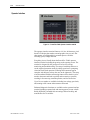
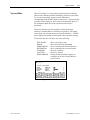
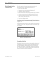
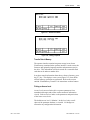
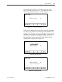
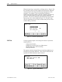
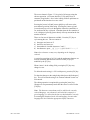
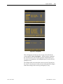
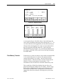
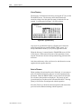
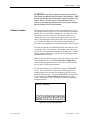
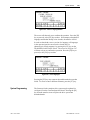
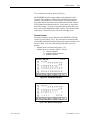
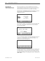
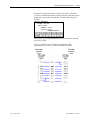
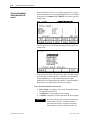
Figure 1.8 – PowerFlex 7000L Operator interface terminal
The operator interface terminal features a 16-line, 40-character, pixel
based LCD display that makes text and graphics easy to read. Bar
chart meters are configurable for common process variables
including speed, voltage and load.
Everything is user friendly about the PowerFlex 7000L operator
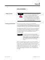
interface terminal including the greeting on the opening screen. The
terminal is designed for the greatest ease of use for start-up,
monitoring and troubleshooting. The setup wizard helps the user to
set the required parameter menus by asking questions or prompting
selections for desired operation. Warnings and comments appear
complete with help text to keep the user on the right track. The setup
wizard combined with the auto-tuning feature allows the drive to be
tuned to the motor and load as quickly and accurately as possible,
resulting in fast start-ups, smooth operation, and less down time.
Up to five test modes are available including low voltage gate check,
and running at full current without motor connected.
Enhanced diagnostic functions are available on the operator interface
terminal including separate fault and warning queues in non-volatile
RAM (NVRAM), extended fault text strings and on line help, and
trend buffers for 16 variables.
7000L-UM302B-EN-P – June 2013
7000 “C” Frame - Marine
Chapter
2
Drive Installation
Safety and Codes
Unpacking and Inspection
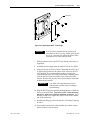
WARNING
The Canadian Electrical Code (CEC), National
Electrical Code (NEC), or local codes outline
provisions for safely installing electrical
equipment. Installation MUST comply with
specifications regarding wire type, conductor
sizes, branch circuit protection and disconnect
devices. Failure to do so may result in personal
injury and/or equipment damage.
Before leaving the factory, all drives have been tested both
mechanically and electrically. Immediately upon receiving the drive,
remove the packing and check for possible shipping damage. Report
any damage immediately to the claims office of the common carrier.
After unpacking the material, check the item(s) received against the
bill of lading to assure that the nameplate description of each item
agrees with the material ordered. Inspect the PowerFlex 7000 drive
for physical damage, as stated in the Rockwell Automation
Conditions of Sale.
I MPORTANT
All claims for breakage and damage whether
concealed or obvious must be made to the carrier
by the Customer as soon as possible after receipt
of the shipment. Rockwell Automation will be
glad to give the Customer reasonable assistance in
the securing of adjustment for such damage
claims.
Remove all packing material, wedges, or braces from within the
drive. Operate the contactors and relays manually to assure that they
operate freely. If any part of the equipment will not be installed
when it is unpacked, it should be stored in a clean, dry place. The
storage temperature must be between -40°C (-40°F) and 70°C
(185°F) with a maximum humidity of 95%, non-condensing, to
guard against damage to temperature sensitive components in the
controller.
7000 “C” Frame - Marine
7000L-UM302B-EN-P – June 2013
2-2
Drive Installation
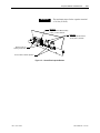
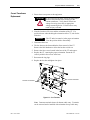
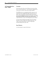
Transportation and Handling
The PowerFlex 7000 drive is shipped on a wooden skid, which is
bolted to the underside of the cabinetry. The drive should remain
bolted to the shipping skid until it is delivered to its final installation
area. Lifting angles are supplied bolted to the top of the cabinetry.
The drive must be kept in an upright position during any handling.
Refer to “General Handling Procedures, publication 7000-IN002_-EN-P
for a more detailed description.
The drive must be transported on a pallet or via use of the lifting
beam supplied as part of all 2300-mm (91-inch) high cabinets.
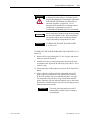
ATTENTION
Ensure that the load rating of the lifting
device is sufficient to safely raise the
controller sections. Refer to the packing slip
enclosed with shipment for shipping
weights.
Round rollers can be used to assist in moving the drive to the
installation site. Once at the final site, the pipe rolling technique can
be used to place the cabinet in the desired position.
WARNING
Care must be exercised when using either a
forklift or the pipe rolling technique for
positioning purposes to ensure that the
equipment is not scratched, dented or
damaged in any manner. Always exercise
care to stabilize the drive during handling to
guard against tipping and injury to personnel.
NOTE: It is extremely important that the customer‟s installation
duties are performed correctly. Any errors will cause damage to the
Drive and delays in commissioning.
Never attempt to lift or move the drive by any means other than the
methods listed, as structural damage or personal injury could result.
The following methods of handling are recommended:
7000L-UM302B-EN-P – June 2013
7000 “C” Frame - Marine
Drive Installation
2-3
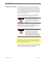
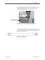
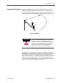
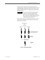
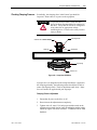
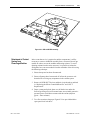
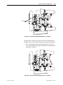
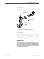
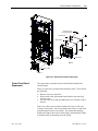
Overhead Lifting
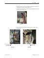
1. Attach rigging to the lifting angles on the top of the cabinetry.
ATTENTION
Ensure that the load rating of the lifting
device and rigging is sufficient to safely
raise the drive. Refer to shipping weights on
the packing slip enclosed with the shipment.
2. Do not pass ropes or cables through the support holes in the
lifting angles. Use slings with safety hooks or shackles.
3. Select or adjust the rigging lengths to compensate for an unequal
weight distribution of load and maintain the drive in an upright
position.
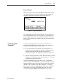
4. To reduce the tension on the rigging and the compressive load on
the lifting device, do not allow the angle between the lifting
cables/chains and vertical to exceed 45 degrees.
ATTENTION
Drives may contain heavy equipment that could
be adversely affected by tilting.
45.0
Max
Figure 2.1 – Overhead Lifting
7000 “C” Frame - Marine
7000L-UM302B-EN-P – June 2013
2-4
Drive Installation
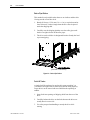
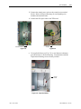
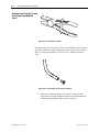
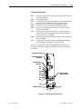
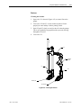
Rod or Pipe Rollers
This method is only suitable when there are no inclines and the drive
is being moved on one floor level.
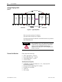
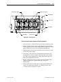
1. Boards 50.8 mm 152.4 mm (2 in. 6 in.) or equivalent and at
least 300 mm (12 inches) longer than the drive must be placed
under the shipping skid.
2. Carefully ease the shipping platform over the roller pipes until
the drive weight is borne on the roller pipes.
3. The drive can be rolled to its designated location. Steady the load
to prevent tipping.
(50.8 mm 152.4 mm)
Figure 2.2 – Rod or Pipe Rollers
Fork Lift Trucks
A single fork lift truck may be used on drives not exceeding 3 m
(120 inches) in length if the lift truck has sufficient lifting capacity.
Larger drives can be moved with two forklift trucks operating in
tandem.
1. Insert forks into openings of shipping skids from the rear of the
drive.
2. Carefully balance the drive on the forks because the drives are
usually heavier at one side.
3. Use safety straps when handling to steady the drive while
moving.
7000L-UM302B-EN-P – June 2013
7000 “C” Frame - Marine
Drive Installation
2-5
Storage
If it is necessary to store the drive, be certain to store in a clean dry
dust free area.
Storage temperature should be maintained between -40°C (-40°F)
and 70°C (185°F). If storage temperature fluctuates or if humidity
exceeds 85%, space heaters should be used to prevent condensation.
The drive should be stored in a heated building having adequate air
circulation. The drive must never be stored outdoors.
Siting of the Drive
Site Considerations
The standard environment in which the equipment is designed to
operate is:
• Elevation above sea level less than 1000 meters (3250 feet)
• Ambient air temperature between 0°C (32°F) and 45°C (113°F)
• Relative humidity of the air not to exceed 95% non-condensing
For the equipment to operate in conditions other than those specified
consult the local Rockwell Automation Sales office.
The equipment requires the following site conditions:
(A)
Indoor installation only, no dripping water or other fluids
(B)
Clean air for cooling requirements
(C)
Level floor for anchoring the equipment. Refer to dimension
drawings for the location of the anchoring points.
(D)
The room in which the equipment is located must allow for full
opening of the doors of the equipment, typically 1200 mm
(48 inches). Also, allowances have to be made for clearance
for fan removal.
or
Dimension drawings can be obtained by contacting the local
Rockwell Automation Sales office. The equipment does not
require rear access for servicing.
(E)
7000 “C” Frame - Marine
Allowance must be made for the stream of cooling air which
exits the drive at the top. The flow of cooling air into and out
the drive must be kept clear and uninhibited.
7000L-UM302B-EN-P – June 2013
2-6
Drive Installation
(F)
The room in which the equipment is located must be large
enough to accommodate the thermal losses of the equipment
since air conditioning may be required; the ambient
temperature must not exceed that for which the equipment is
rated. The heat created by the drive is directly proportional to
the power of the motor being driven and the efficiency of
equipment within the room.
(G)
The area in which the drive is located should be free of radio
frequency interference such as encountered with some welding
units. This may cause erroneous fault conditions and shut
down the drive.
(H)
The equipment must be kept clean. Dust in the equipment
decreases system reliability and inhibits cooling.
(I)
Power cable lengths to the motor are virtually unlimited due to
the near sinusoidal voltage and current waveforms. Unlike
voltage source drives, there are no capacitive coupling, dv/dt,
or peak voltage issues that can damage the motor insulation
system. The CSI-PWM topology utilized in the PowerFlex 7000
medium voltage AC drive has been tested with motors located
up to 15 km (9.3 miles) from the drive.
(J)
Only personnel familiar with the function of the drive should
have access to the equipment.
(K)
The drive is designed for front access and should be installed
with adequate and safe clearance to allow for total door
opening. The back of the unit may be placed against a wall
although some customers prefer back access also. If back
access is desired, set drive 300 mm (12 inches) out from wall.
ATTENTION
7000L-UM302B-EN-P – June 2013
An incorrectly applied or installed drive can
result in component damage or a reduction in
product life. Ambient conditions not within
the specified ranges may result in
malfunction of the drive.
7000 “C” Frame - Marine
Drive Installation
Installation
2-7
When the drive has been placed at its installation area, the lag bolts
that fasten the shipping skid to the drive must be removed. The drive
is moved off the shipping skid and the shipping skid can be
discarded.
Position the drive in its desired location. Verify that the drive is on a
level surface and that the position of the drive will be vertical when
the anchor bolts are installed.
The location of the anchor points is provided with the dimension
drawing of the drive.
Install and tighten the anchor bolts. (M12 or ½” hardware required).
Engineered bolt systems are required for seismic requirements.
Consult factory.
Remove the top lifting angles, retain the hardware.
An additional set of mounting brackets has been supplied by
Rockwell Automation for securing the drive to the roof for roll and
pitch concerns. The hardware removed for the lifting angles are to
be used to secure these brackets to the drive. An additional
mounting drawing, specific for the order, should be used to
understand how to brace the drive to the vessel structure using these
brackets. If this drawing cannot be located, please contact Rockwell
Automation Sales office.
Joining Shipping Splits
The Drive may have been shipped in two or more shipping sections
which are to be connected at installation. It is essential that the
surfaces are level. Arrange the sections per the information provided
in the dimension drawings and move the sections together. Ground
bus, power and control connections are to be made per the electrical
diagrams provided. Side sheets of the enclosures are to be joined
with thread forming screws using the available holes.
Liquid-cooled Drives may require joining of the coolant pipes.
Some enclosure ratings may require the addition of silicone sealant
where cabinets join together to prevent the possible ingress of dripping
water.
For some Direct-to-Drive liquid-cooled Drives (6600V - 430A / 495A
/ 575A rated) the Drive will be shipped in two sections as shown in
Figure 2.3.
7000 “C” Frame - Marine
7000L-UM302B-EN-P – June 2013
2-8
Drive Installation
Joining Shipping Splits
(cont.)
LR
CAB
1
Lifting Angles
CABLE
CAB
2
CONV
CAB
3
CAP
CAB
4
DC LINK
CHOKE
CAB
6
CAP
CAB
5
Wood Skid
1st SECTION
PUMP
CAB
7
2nd SECTION
Figure 2.3 – Typical Split Drive
The 1st section consists of 5 cabinets.
The 2nd section consists of 2 cabinets.
Final placement requires that the 1st and 2nd sections are joined at
final installation site.
WARNING
Connect the Sections
Heavy Magnetic DC Link Chokes up to 4600 kg
(10,000 lbs) are shipped inside DC Link Choke
cabinet. Professional Millwright/Rigging
contractors are required for safe final placement
of Drive sections.
Field connect the following:
CPVC pipe splices – 2 pieces
Power Bus Splice Kit – 4 pieces
Ground Bus Splice – 1 piece
Control Wiring
Tools Required (not supplied)
7000L-UM302B-EN-P – June 2013
Adjustable or socket wrenches for 6-, 10-, 12-mm and 5/8”
bolt and nut hardware
Strap wrench for tightening CPVC unions
Screwdriver assortment
Cable ties
Wire cutters
7000 “C” Frame - Marine
Drive Installation
2-9
Install CPVC Piping Splices
Open doors of capacitor cabinet (Cabinet #5) next to DC Link Choke
cabinet (Cabinet #6). Refer to Figure 2.4.
Remove capacitor from position #3, if installed (not all
configurations have a capacitor in this location). It is not necessary
to remove capacitor from position # 2.
ATTENTION
Capacitors weigh up to 100 kg (220 lbs). Use
two people to remove the unit from the
structure.
CPVC Pipe
Splices
Capacitor
Position #1
Capacitor
Position #2
Capacitor
Position #3
Figure 2.4 – Capacitor Cabinet
7000 “C” Frame - Marine
Remove CPVC pipe splices shipped in the capacitor cabinet. Install
and tighten the 4 CPVC unions with strap wrench (¼ to ½ turn past
hand tight). Ensure O-ring is seated inside male end of union. Refer
to Figures 2.5, 2.6, 2.7 and 2.8. Do not use CPVC primer or cement.
7000L-UM302B-EN-P – June 2013
2-10
Drive Installation
Connect the Sections
(cont.)
Pipe Splice #2
Pipe Splice #1
Capacitor
Cabinet
DC Link
Choke Cabinet
Figure 2.5 – CPVC Pipe Splices (Capacitor #2 not shown for clarity)
Figure 2.6 – Typical Strap Wrench (not supplied)
used to tighten unions on CPVC pipe splices
7000L-UM302B-EN-P – June 2013
7000 “C” Frame - Marine
Drive Installation
2-11
Pipe Splice #1
Pipe Splice #2
Figure 2.7 – Capacitor Cabinet after pipe
splices installed
Figure 2.8 – DC Link Choke Cabinet after
pipe splices installed
Note: Install according to flow direction labels as shown.
Connect Power: M+, L+, M-, L- Power Bus
7000 “C” Frame - Marine
Locate the four (4) Power Bus pieces of the splice kit in DC Link
Choke cabinet and remove shipping wrapping. See Figure 2.9.
Connect Power Bus M+, L+, M-, L- on the red insulators in the DC
Link Choke cabinet and mating bus pieces in the capacitor cabinet.
Hardware required is pre-attached to bus connections, cabling, and
insulators in the cabinet where the power bus splice kit will attach.
Remove and attach as shown in Figures 2.9 to 2.13.
Torque M10 carriage bolts connecting bus to bus in the capacitor
cabinet to 29 Nm (21 ft-lbs). Torque M12 hardware supplied for
cable to bus stab connections to 50 Nm (37 ft-lbs).
After cable connections have been made, ensure cable connections to
choke stabs are torqued to 50 Nm (37 ft-lbs)
Ensure a minimum of 3” (75mm) clearance exists between Medium
Voltage Bus field connections (including hardware)
and all cabinet sidesheets.
7000L-UM302B-EN-P – June 2013
2-12
Drive Installation
Connect the Sections
(cont.)
MV Bus (4 pieces)
Ground Bus Link (1 piece)
Inside DC Link Choke Cabinet
Figure 2.9 – DC Link Choke Cabinet
Power Bus (4) pieces; Ground bus (1) shipped disassembled
M+
M-
L+
L-
Figure 2.10 – DC Link Choke Cabinet before field power bus connections
7000L-UM302B-EN-P – June 2013
7000 “C” Frame - Marine
Drive Installation
2-13
M+
L+
M-
L-
Figure 2.11 – DC Link Choke Cabinet after field connections of power bus
M+
L+
LM-
Figure 2.12 – Capacitor Cabinet after field connections of power bus
7000 “C” Frame - Marine
7000L-UM302B-EN-P – June 2013
2-14
Drive Installation
Connect the Sections (cont.)
M+
L+
M10 Carriage Bolt
M10 Washer
M10 Lockwasher
M10 Nut
MLFigure 2.13 – Capacitor Cabinet
(Connect left side of Medium Voltage bus pieces with M10 hardware)
Connect cables from DC Link Choke to MV Bus pieces using
supplied M12 hardware.
M+
L+
M-
L-
Figure 2.14 – DC Link Choke Cabinet after connection of cables from DC Link Choke to red insulators
7000L-UM302B-EN-P – June 2013
7000 “C” Frame - Marine
Drive Installation
•
2-15
Connection points are labeled on bus and DC Link Choke. Connect
cables from labeled stabs M+, L+, L-, L+ on DC Link Choke to
corresponding labeled stabs M+, L+, M-, L+ on bus.
Typical cable connection
from DC link choke to bus
Figure 2.15 – DC Link Choke Cabinet Typical Cable Connection
•
Connect Ground Bus Link from top left of DC Link Choke cabinet to
ground bus in adjacent capacitor cabinet by sliding underneath wire
duct. Use supplied hardware.
Figure 2.16 – Ground Bus Link
7000 “C” Frame - Marine
7000L-UM302B-EN-P – June 2013
2-16
Drive Installation
Connect the Sections (cont.)
Figure 2.17 – Install Ground Bus Link
M6 Hardware (4 places)
tighten to 6 Nm (4.4 ft-lbs)
at each end of bus link
Figure 2.18 – Ground Bus Connection Points
(Install Ground Bus Link using Supplied Hardware)
7000L-UM302B-EN-P – June 2013
7000 “C” Frame - Marine
Drive Installation
Control Wiring
Connections
2-17
Refer to Electrical Drawings and wiring diagrams supplied with
Drive. Contact Rockwell Automation representative for assistance.
Final wiring connections to be performed by Rockwell Automation
field service representative.
1. Remove the wireway covers located on top of the line and motor
filter capacitor sections and the DC Link section.
2. If drive has strip heater wiring, it will be coiled up in the top
wireway. Route these wires down through the grommeted cutout for
connection on the terminal blocks located in the upper left side of the
capacitor section.
Figure 2.19 – Strip heater terminal block
3. Route the control wiring which has been coiled up and left hanging
in the upper area of the motor filter capacitor section, back up through
the two grommeted cutouts back into the wireway. There is a fiber
optic cable in this bundle and care must be taken not to damage it.
The fiber optic cable, control power wires and the “XIO link” cable
will be required in the pump control cabinet.
Figure 2.20 – Control Wiring
7000 “C” Frame - Marine
7000L-UM302B-EN-P – June 2013
2-18
Drive Installation
Control Wiring
Connections (cont.)
4. Route the 8 gauge black and red twisted pairs of wire and the Belden
shielded cables down through the grommeted cutout into the AC\DC
power supply section.
Figure 2.21
5. Route the 3-fan control wires, 2 cabinet over-temperature control
wires down through the grommeted cutout into the center of the DC
choke section (Figure 2.22).
Figure 2.22 – Fan • Thermostat Control Wires
7000L-UM302B-EN-P – June 2013
7000 “C” Frame - Marine
Drive Installation
2-19
6. Route the control wires down through the grommeted cutout into the
control power disconnect section (Figure 2.23).
7. Connect the numbered wires to the corresponding numbered terminal
blocks (Figures 2.24 to 2.27).
Figure 2.23
8. Refer to the electrical drawing and make the above control wiring
connections.
56V DC Connections
Red – Positive
Black – Negative
AC DC fails Belden
cable connections
Figure 2.24
7000 “C” Frame - Marine
Figure 2.25
7000L-UM302B-EN-P – June 2013
2-20
Drive Installation
Control Wiring
Connections (cont.)
Control Wire Power Connections
Figure 2.26
Thermostat and Fan Connections
Figure 2.27
9. Once all the connections have been made and neatly routed in each
section, the excess control wires can be looped up in the top
wireways.
10. Swing out the control section in the pump control cabinet.
11. Route the XIO link cable, control power wires and the fiber optic
cable down through the wire ways grommeted cutout.
12. Route the XIO link cable, the control power wires into the pump
control cabinet through the upper side grommeted cutout.
13. Route the fiber optic cable into the pump control cabinet through the
lower side grommeted cutout.
Figure 2.28 -– 120 volt and XIO cables through upper cutout
14. Connect the XIO link cable to the XIO board “XIO link A”
connector. (Figure 2.29)
7000L-UM302B-EN-P – June 2013
7000 “C” Frame - Marine
Drive Installation
2-21
15. Connect the control power wires to the control power terminal
blocks. Refer to Electrical Drawings for corresponding wire
numbers and terminal blocks.
16 Connect the fiber optic cable to the TFB board.
TFB Fiber optic
connected
XIO link cable
connected to XIO link A
Figure 2.29
Figure 2.30
Use supplied silicone (see Fig. 2.31) to seal between cabinets to
prevent moisture or dirt from entering. Join sidesheets with M6
Taptite thread forming screws in holes provided.
Silicone
sealant
Figure 2.31 – Capacitor Cabinet
7000 “C” Frame - Marine
7000L-UM302B-EN-P – June 2013
2-22
Drive Installation
Removal of DC Link Choke Turnbuckle Supports (if used on design supplied)
Remove turnbuckles which attach choke to top lifting angle pair as
follows:
Remove cotter pins (see Fig. 2.32) from bottom turnbuckle jaw then
top. Carefully remove turnbuckles. Retain for future use.
Remove cotter pins
Figure 2.32 – Choke Cabinet
7000L-UM302B-EN-P – June 2013
Re-install any capacitors that were removed.
Proceed with Removal of Lifting Angles.
7000 “C” Frame - Marine
Drive Installation
2-23
Removal of Lifting Angles Lifting angles should be removed only when the Drive is in its final
location. The lifting angles are retained with 5/8”-11 hardware. The
5/8” bolts need to be re-installed in their holes in the top of the Drive to
prevent the ingress of foreign matter into the enclosures. See Figure 2.33.
Figure 2.33 – Insert bolts.
ATTENTION
Refer to the technical drawings and installation
manual for your Drive mounting instructions.
Failure to correctly anchor the cabinet may result
in damage to the equipment or injury to personnel.
Contact the area Rockwell Automation sales
office if you do not have these documents.
An additional set of mounting brackets has been supplied by Rockwell
Automation for securing the drive to the roof for roll and pitch concerns.
The hardware removed for the lifting angles are to be used to secure
these brackets to the drive. An additional mounting drawing, specific for
the order, should be used to understand how to brace the drive to the
vessel structure using these brackets. If this drawing cannot be located,
please contact Rockwell Automation Sales office.
7000 “C” Frame - Marine
7000L-UM302B-EN-P – June 2013
2-24
Drive Installation
Shock Indication Labels
Shock indication labels are devices that permanently record the
physical shock to which equipment is subjected.
At the time of final preparation for shipment from the factory, a
shock indication label is installed on the inside door of the converter
cabinet.
During the shipping and installation process drives may
inadvertently be subjected to excess shock and vibration which may
impair its functionality.
When the drive has been placed in its installation area, the converter
door is to be opened and the shock indication labels inspected.
The drive is shipped with a label that records shock levels in excess
of 10G. If these shock levels have been attained, the chevron shaped
window will appear blue in one of the two windows.
If these shock levels have been attained, record the values. There is a
greater possibility of the drive having sustained internal damage if it
has been subjected to physical shock during the shipping and
installation process.
Even if the indicators show that no shock was attained, full
inspection and verification in accordance with the Commissioning
process outlined in Chapter 4 is still essential.
Red Plastic Housing
51 mm
(2.0)
Window Area appears Blue
if subjected to shock
21 mm
(0.8)
Figure 2.34 – Shock Indicator
7000L-UM302B-EN-P – June 2013
7000 “C” Frame - Marine
Drive Installation
2-25
Installation of Exhaust Air Hood
Even though this is a liquid-cooled drive, some sections still require
air circulation.
On the top of the cabinets with cooling fans, sheet metal exhaust
hoods are to be installed. The components to make up the exhaust
hood have been packaged and shipped with the drive and are to be
found on a separate skid marked with the same identifying tags on
the skid.
The first step is to remove the protective plate covering the fan
opening on the drive. It is a flat cover plate bolted to the top plate.
Remove the bolts and plate and keep the hardware for reuse.
Secondly, locate the fan hoods on the separate skid and lift these
over the respective holes located on the top of the drive cabinet.
Locate the exhaust hood on top of the cabinet per Figure 2.35 and
reuse the existing hardware set aside earlier. (Care must be taken
that the notches on the bottom flange are oriented toward the sides of
the drive). Affix assembly to the drive top plate. Tighten all
hardware.
ATTENTION
7000 “C” Frame - Marine
Any screws that are accidentally dropped in
the equipment must be retrieved as damage
or injury may occur.
7000L-UM302B-EN-P – June 2013
2-26
Drive Installation
Internally mounted fans
Capacitor cabinets have internally mounted fans which are installed
and wired by Rockwell Automation (refer to Figure 2.35). The
customer only needs to install the fan hood.
Fan Hood to be installed on site
Internally mounted fans
Figure 2.35 – Fan Hood Installation (Internally Mounted Fans)
7000L-UM302B-EN-P – June 2013
7000 “C” Frame - Marine
Drive Installation
2-27
Externally mounted fans and fan hood
The converter has cooling fans that are externally mounted (refer to
Figure 2.36). It is necessary to re-install and connect the fans, and
install the fan hood.
Shipped with the drive is a plate with the fans mounted and wired to
terminal blocks. On site, the fan assembly is to be mounted on the
top plate of the converter cabinet as shown in Figure 2.36.
Wiring for fan power is to be routed through the hole near the terminal
blocks. The plate is fastened to the cabinet with M6 hardware.
Connect wires to the terminal blocks per the electrical diagram.
Position the fan hood over the fan assembly and fasten with M6
hardware.
Fan Hood
External fans
Terminal blocks
Figure 2.36 – Fan Hood Installation (Externally Mounted Fans and Fan Hood)
7000 “C” Frame - Marine
7000L-UM302B-EN-P – June 2013
2-28
Drive Installation
Cabinet Layout and
Dimensional Drawings
of Drive
7000L-UM302B-EN-P – June 2013
Generic Dimensional Drawings have not been included in this user‟s
manual. Please reference the order specific project drawings for
detailed dimensions of conduit openings and mounting penetrations.
7000 “C” Frame - Marine
Drive Installation
2-29
Figure 2.37 – Typical Footprint PowerFlex 7000 “C” Frame Marine Drive Structure Layout
7000 “C” Frame - Marine
7000L-UM302B-EN-P – June 2013
2-30
Drive Installation
Figure 2.38 – Typical Footprint PowerFlex 7000 “C” Frame Marine Drive Structure Layout
7000L-UM302B-EN-P – June 2013
7000 “C” Frame - Marine
Drive Installation
Control/Cabling Cabinet
2-31
Shows the medium voltage area located in the control/cabling
cabinet behind the low voltage compartment and with barriers
removed.
Note: The control/cabling cabinet comes in two different
configurations:
Large Footprint AFE rectifier (Figure 2.37)
Small Footprint AFE rectifier (Figure 2.38)
Major Components
7000 “C” Frame - Marine
The following diagrams are presented to show what the typical
layout of each cabinet will be for the PowerFlex 7000 “C” Frame
Marine Drive.
7000L-UM302B-EN-P – June 2013
2-32
Drive Installation
Hall-Effect Sensor
Voltage Sensing
Hall-Effect Sensor
Motor Terminals
Surge Arresters
Line Terminals
Current Transformer
Figure 2.39 – General Control and Cabling Cabinet
(with Control Panel removed)
7000L-UM302B-EN-P – June 2013
7000 “C” Frame - Marine
Drive Installation
2-33
Customer
Wiring
Terminals
Analog
Control
Board
ANALOG
CONTROL
BOARD
Fiber Optic
Interface
Boards
Tach Feedback
Circuit Board
DC/DC
Power
Supply
Drive Processor
Module (DPM)
Figure 2.40 – Low Voltage Tub Compartment
7000 “C” Frame - Marine
7000L-UM302B-EN-P – June 2013
2-34
Drive Installation
Ground Bus
Inverter Modules
Coolant Piping
Gate Drive
Power Supplies
Rectifier Modules
Figure 2.41 – Converter Cabinet
7000L-UM302B-EN-P – June 2013
7000 “C” Frame - Marine
Drive Installation
2-35
Dynamic
Braking
Resistor
Cooling Fans
Dynamic Braking
Chopper Modules
Coolant Piping
Figure 2.42 – Dynamic Braking Cabinet
7000 “C” Frame - Marine
7000L-UM302B-EN-P – June 2013
2-36
Drive Installation
Motor Filter
Capacitors
Line Filter
Capacitors
Figure 2.43 – Capacitor Cabinet
7000L-UM302B-EN-P – June 2013
7000 “C” Frame - Marine
Drive Installation
2-37
AC/DC Power Supplies
Disconnect
Switch
Power Transformers
Liquid-Cooled
DC Link Reactor
Cooling Pipes
Figure 2.44 – DC Link Inductor Cabinet
7000 “C” Frame - Marine
7000L-UM302B-EN-P – June 2013
2-38
Drive Installation
De-ionizer
Cartridge
Pumping Panel
Coolant Reservoir
(behind L.V. Panel)
Swingout
Low Voltage
Panel
Heat Exchanger
Coolant Pumps
Figure 2.45 – Pump Cabinet (showing swing-out low voltage panel)
7000L-UM302B-EN-P – June 2013
7000 “C” Frame - Marine
Drive Installation
2-39
Ground Bus
Surge Suppression
Network
Line Capacitors
Hall Effect Sensor
Voltage Sensing
Line Terminals
Figure 2.46 – Line Reactor and Incoming Cabling Cabinet
7000 “C” Frame - Marine
7000L-UM302B-EN-P – June 2013
2-40
Drive Installation
Hall Effect Sensors
Line Terminals
Ground Fault
Current Transformer
Figure 2.47 – General Incoming Cabling Location (Line Reactor section)
7000L-UM302B-EN-P – June 2013
7000 “C” Frame - Marine
Drive Installation
2-41
Ground Bus
Inverter Modules
Coolant Piping
Gate Drive
Power Supplies
Rectifier Modules
Figure 2.48 – Converter Cabinet
7000 “C” Frame - Marine
7000L-UM302B-EN-P – June 2013
2-42
Drive Installation
Output
Isolation Switch
AC/DC
Power Supplies
Output
Isolation Switch
Handle
Disconnect Switch
Output
Contactor
Power Transformers
Liquid-cooled
DC Link Reactor
Coolant Pipes
Figure 2.49 – Capacitor and CMC Cabinet
7000L-UM302B-EN-P – June 2013
7000 “C” Frame - Marine
Drive Installation
2-43
Customer
Terminal
Blocks
Output
Contactor
Control
Module
Customer
I/O Control
Board (XIO)
Drive
Control
Boards
(ACB)
Communication
Card
Marine UPS
Figure 2.50 – Pump Cabinet (showing swing-out low voltage panel)
7000 “C” Frame - Marine
7000L-UM302B-EN-P – June 2013
2-44
Drive Installation
Grounding
Network
De-ionizer
Cartridge
Motor Filter
Capacitors
Heat
Exchanger
Motor
Terminals
Coolant
Pumps
Voltage
Sensing
Figure 2.51 – Pump Cabinet (swing-out low voltage panel removed)
7000L-UM302B-EN-P – June 2013
7000 “C” Frame - Marine
Drive Installation
2-45
Removable cover for
access to load cables
UPS and Battery pack
Removable cover for
access to local cables
Figure 2.52 – Access to Load Terminals (components installed)
Voltage Sensing
Board (VSB)
Figure 2.53 – Access to Load Terminals (bottom covers removed)
7000 “C” Frame - Marine
7000L-UM302B-EN-P – June 2013
2-46
Drive Installation
Removable cover for
access to load cables
with UPS removed
Figure 2.54 – Access to Load Terminals (bottom covers and UPS removed)
Load cable terminals
with barrier plate
removed
Figure 2.55 – Access to Load Terminals (bottom covers, UPS and terminal barrier removed)
7000L-UM302B-EN-P – June 2013
7000 “C” Frame - Marine
Drive Installation
2-47
Motor Terminals
Voltage Sensing
Figure 2.56 – Motor Cable termination point
Load Cable Removable
Conduit Cover
Figure 2.57 – Motor Cable termination point (Removable gland plate)
7000 “C” Frame - Marine
7000L-UM302B-EN-P – June 2013
2-48
Drive Installation
IEC Component and Device
Designation
PowerFlex 7000 electrical drawings use conventions that are based
on IEC (International Electrotechnical Commission) standards, while
remaining basically compatible with North American ANSI
(American National Standards Institute) standards. The symbols
used to identify components on the drawings are international and a
full listing of the symbols is given as part of each PowerFlex 7000
elementary drawing (ED) set. The device designations used on the
drawings and labeling are also listed with explanations on each
drawing set.
Wiring identification uses a source/destination wire number
convention on point to point multi-conductor wiring and in situations
where the system is warranted. The wire-numbering system of
unique, single numbers for multi-drop and point to point wiring
continues to be used for general control and power wiring. Wiring
that connects between the sheets or that ends at one point and starts
at another point on a drawing has an arrow and drawing reference to
indicate the ongoing connection. The drawing reference indicates
the sheet and the X/Y coordinates of the continuation point. The
reference system is explained on a sheet in each drawing set. The
unique wire numbering system serves as confirmation that the
correct wire is being traced from sheet to sheet or across a drawing.
Wires in multi-conductor cables are typically identified by color
rather than by number. The abbreviations used to identify the colors
on the drawings are fully identified on a sheet in the drawing set.
Power Wiring Selection
The following tables identify general wire selections that will be
encountered when installing the PowerFlex 7000 drive line-up.
General Notes:
Adherence to the following recommended field power cabling
insulation levels for medium voltage drives will help to ensure
trouble-free start-up and operation. The cable insulation level must
be increased over that which would be supplied for an across-the-line
application with the same rated line-to-line voltage.
Either shielded or unshielded cable may be used based on the criteria
considered by the distribution system designer, applicable marine
standard(s) requirements and local standards. However, NEC
requires shielded cable for installations above 2 kV.
7000L-UM302B-EN-P – June 2013
7000 “C” Frame - Marine
Drive Installation
2-49
Cable Insulation
The cable insulation requirements for the PowerFlex 7000 drive are
given in the tables below.
ATTENTION
Voltage ratings shown in the following
tables are peak line-to-ground. Some cable
manufacturers rate voltage line-to-line RMS.
Ensure the cable meets the rating specified
in the following tables.
Cable Insulation Requirements for 18P and 6P / AFE Drives with Isolation
Transformer
System Voltage (V, RMS)
2400
3000
3300
4160
6000
6300
6600
Cable Insulation Rating (kV)
(Maximum Peak Line-to-Ground)
Line Side
Machine Side
4.1
2.2
5.12
2.75
5.63
3.0
7.1
3.8
10.8
5.5
11.4
5.8
11.8
6.0
Cable Insulation Requirements for “Direct-to-Drive” Technology
System Voltage (V, RMS)
2400
3000
3300
4160
6000
6300
6600
7000 “C” Frame - Marine
Cable Insulation Rating (kV)
(Maximum Peak Line-to-Ground)
Line Side
Machine Side
2.2
2.2
2.75
2.75
3.0
3.0
3.8
3.8
5.5
5.5
5.8
5.8
6.0
6.0
7000L-UM302B-EN-P – June 2013
2-50
Drive Installation
The following table identifies general wire categories that will be encountered when installing the
PowerFlex 7000 Drive. Each category has an associated wire group number that is used in the following
sections to identify the wire to be used. Application and signal examples along with the recommended
type of cable for each group are provided. A matrix providing the recommended minimum spacing
between different wire groups run in the same tray or separate conduit is also provided.
For Tray:
Recommended spacing between different wire groups in the same tray.
For Conduit: Recommended spacing for wire groups in separate conduit – mm (inches).
Wire
Category
Wire
Group
Application
Signal
Example
Recommended
Cable
Wire
Group
Power
1
Power
2
Control
3
Control
4
1
AC Power
(> 600V AC)
2.3 kV, 3
AC Lines
Per IEC / NEC
Local Codes and
Application
Requirements
In
Tray
228.6
(9.00)
228.6
(9.00)
228.6
(9.00)
228.6
(9.00)
Between
Conduit
Power
2
AC Power
(TO 600V AC)
480V, 3
Per IEC / NEC
Local Codes and
Application
Requirements
In
Tray
Control
4
115V AC
or 115V DC
Logic
Relay Logic
PLC I/O
115V AC
Power
Power Supplies
Instruments
24V AC
or 24V DC
Logic
PLC I/O
Per IEC / NEC
Local Codes and
Application
Requirements
In
Tray
228.6
(9.00)
In
Tray
228.6
(9.00)
Signal
6
Analog Signals
DC Supplies
5-24V DC
Supplies
Digital
(Low Speed)
Power Supplies
TTL Logic Level
Pulse Train
Input
Tachometer
PLC
Communications
Digital
(High Speed)
152.4
(6.00)
152.4
(6.00)
152.4
(6.00)
228.6
(9.00)
152.4
(6.00)
76.2 (3.00)
Between Conduit
228.6
(9.00)
Between
Conduit
5
228.6
(9.00)
76.2 (3.00)
Between Conduit
Between
Conduit
Per IEC / NEC
Local Codes and
Application
Requirements
Signal
6
76.2 (3.00)
Between Conduit
Between
Conduit
3
Signal
5
152.4
(6.00)
152.4
(6.00)
228.6
(9.00)
76.2 (3.00)
Between Conduit
Belden 8760
Belden 8770
Belden 9460
Belden 8760
Belden 9460
Belden 9463
All signal wiring must be run in separate steel conduit.
A wire tray is not suitable.
The minimum spacing between conduits containing different
wire groups is 76.2 mm (3 inches).
Belden 8760 - 18 AWG, twisted pair, shielded
Belden 8770 - 18 AWG, 3 conductor, shielded
Belden 9460 - 18 AWG, twisted pair, shielded
Belden 9463 - 24 AWG, twisted pair, shielded
Note 1: Steel conduit or cable tray may be used for all PowerFlex 7000 Drive power or control wiring, and steel conduit is required for all PowerFlex 7000 Drive
signal wiring. All input and output power wiring, control wiring or conduit should be brought through the drive conduit entry holes of the enclosure. Use
appropriate connectors to maintain the environmental rating of the enclosure. The steel conduit is REQUIRED for all control and signal circuits, when the drive is
installed in European Union countries. The connection of the conduit to the enclosure shall be on full 360 degree and the ground bond at the junction shall be
less than 0.1 ohms. In EU countries this is a usual practice to install the control and signal wiring.
Note 2: Spacing between wire groups is the recommended minimum for parallel runs of 61 m (200 feet) or less.
Note 3: The customer is responsible for the grounding of shields. On drives shipped after November 28/02, the shields are removed from the drive boards. On
drives shipped prior to November 28/02, all shields are connected at the drive end and these connections must be removed before grounding the shield at the
customer end of the cable. Shields for cables from one enclosure to another must be grounded only at the source end cabinet. If splicing of shielded cables is
required, the shield must remain continuous and insulated from ground.
Note 4: AC and DC circuits must be run in separate conduits or trays.
Note 5: Voltage drop in motor leads may adversely affect motor starting and running performance. Installation and application requirements may dictate that
larger wire sizes than indicated in IEC / NEC guidelines are used.
Table 2.A – Wire Group Numbers
7000L-UM302B-EN-P – June 2013
7000 “C” Frame - Marine
Drive Installation
2-51
The wire sizes must be selected individually, observing all applicable
safety and CEC or IEC / NEC regulations. The minimum permissible
wire size does not necessarily result in the best operating economy.
The minimum recommended size for the wires between the drive and
the motor is the same as that used if a main voltage source
connection to the motor was used. The distance between the drive
and motor may affect the size of the conductors used.
Consult the wiring diagrams and appropriate CEC or IEC / NEC
regulations to determine correct power wiring. If assistance is
needed, contact your local Rockwell Automation Sales Office.
Power Cabling Access
The drive is built with provision for either the top or bottom power
cable entry.
Cable access plates are provided on the top and bottom plates of the
connection cabinet identified by the customer specific dimension
drawing.
To Access the Customer Power Cable Terminations:
•
Open the door of the low voltage control compartment. The low
voltage control compartment is hinged on its left side. The
power terminals are behind the low voltage control compartment.
•
Note that there is a key interlock to prevent swinging the low
voltage control compartment open unless the medium voltage
source is locked out.
•
Turn each of the three latches on the right side of the low voltage
compartment one-quarter turn using an 8-mm hexagonal key
wrench. There is a pull handle provided on the right side of the
low voltage compartment.
•
Slowly pull the handle so that the low voltage compartment
swings out. The power terminals are now visible.
The installer is responsible for modifying the power cable access
plates to suit the requirements.
Note that appropriate connectors must be used to maintain the
environmental rating of the enclosure.
7000 “C” Frame - Marine
7000L-UM302B-EN-P – June 2013
2-52
Drive Installation
Latch
Key Interlock
Handle
Latch
Terminal blocks
- Customer (TBC)
Figure 2.58 – Swing-out of Low Voltage Compartment
7000L-UM302B-EN-P – June 2013
7000 “C” Frame - Marine
Drive Installation
Power Connections
2-53
The installer must ensure that interlocking with the upstream power
source has been installed and is functioning.
The installer is responsible for ensuring that power connections are
made to the equipment in accordance with local electrical codes.
The drive is supplied with provision for cable lugs. The power
terminals are identified as follows:
Incoming Connections
•
Drives with AFE Rectifiers:
2U, 2V, 2W
•
Drives with 18-Pulse Rectifiers
- Secondary (d0)
- Secondary (d-20)
- Secondary (d+20)
2U, 2V, 2W
3U, 3V, 3W
4U, 4V, 4W
Motor Connections
U, V, W
•
The installer is responsible for ensuring that power connections are
made with appropriate torque. (Refer to Appendix B "Torque
Requirements" in back of manual.)
The drive is supplied with provision for grounding of cable shields
and stress cones near the power terminals.
7000 “C” Frame - Marine
7000L-UM302B-EN-P – June 2013
2-54
Drive Installation
Liquid Connections
Liquid-to-Liquid Heat Exchangers
There are three options for routing piping between the liquid-toliquid heat exchanger to the supply and return coolant:
•
•
•
Pipes through top plate of cabinet
Pipes through bottom plate of cabinet
Pipes through right side of cabinet
Removable plates are provided in each of these locations.
Access for connections
through top of cabinet
Access for connections
to heat exchanger through
right side of cabinet
Liquid-to-Liquid
Heat Exchanger
Access for connections
to heat exchanger through
bottom of cabinet
Figure 2.59 – Connection to Liquid-to-Liquid Heat Exchanger
(rear of pumping cabinet shown with back plates removed)
7000L-UM302B-EN-P – June 2013
7000 “C” Frame - Marine
Drive Installation
2-55
Figure 2.60 – Conduit opening plate for bottom entry of plumbing from customer’s coolant loop
Figure 2.61 –Customer connection points to internal Heat Exchanger for external coolant loop
7000 “C” Frame - Marine
7000L-UM302B-EN-P – June 2013
2-56
Drive Installation
1.25” or 2.0” NPTF
Female Pipe Threads
Drive Coolant Outlet
Drive Coolant Inlet
Process Water Outlet
Process Water Inlet
Figure 2.62 – Pipe Flange Detail
Please refer to project Specific drawings for detailed requirements for the coolant flow
and pressures required.
7000L-UM302B-EN-P – June 2013
7000 “C” Frame - Marine
Drive Installation
Power and Control Wiring
2-57
Drive line-ups (i.e. Drive and Input Starter) which are delivered in
two or more sections, for ease of handling, will require that the
power and control wiring be re-connected. After the sections are
brought together, the power and control wiring is to be reconnected
as per the schematic drawings provided.
Control Cables
Control cable entry/exit should be located near the terminal block
'TBC' – the customer's connections are to be routed along the
empty side of the TBC terminals. These terminals are sized to
accept a maximum AWG #14 wire gauge. The low voltage signals
(includes 4-20mA) are to be connected using twisted shielded
cable, with a minimum AWG #18 wire gauge. (Based on using a
W4 terminal block for customer connections, comparable wire
sizes would be 0.5 – 4 mm2 as equivalent to #22-#10 AWG.)
Of special concern is the tachometer signal. Two tachometer inputs
are provided to accommodate a quadrature tachometer (senses motor
direction). The tachometer power supply is isolated and provides
+15 Volts and a ground reference. Many tachometer outputs have an
open collector output, in which case a pull-up resistor must be added
to ensure that proper signals are fed to the system logic. (Refer to
Appendix A "When is a Tachometer Required?" to see if one
needs to be supplied.)
I MPORTANT
7000 “C” Frame - Marine
Low voltage signals are to be connected using
twisted shielded cable with the shield connected at
the signal source end only. The shield at the other
end is to be wrapped with electrical tape and
isolated. Connections are to be made as shown on
the drawings provided.
7000L-UM302B-EN-P – June 2013
2-58
Drive Installation
Power and Control Wiring
(cont.)
Encoder Installation Guidelines
The most frequent problems encountered when transmitting an
encoder‟s signal(s) to the drive are signal distortion and electrical
noise. Either of these problems can result in a gain or loss of encoder
data counts (quadrature encoders) or corrupt positional data (absolute
encoders). Many of these problems can be avoided by applying good
installation and wiring practices. This section is a general guideline
and recommended practices for field installed equipment. It applies
to either encoder board and both quadrature and absolute encoders.
• Protection from Radiated and Conducted Noise
Reasonable care should be taken when connecting and routing power
and signal wiring on a machine or system. Radiated noise from nearby
relays, solenoids, transformers, non linear loads (such as motor drives)
etc. can couple onto signal wires producing undesired pulses. In fact
the encoder itself may induce noise into signal lines run adjacent to it.
To avoid radiated and/or conducted noise, power and signal lines
should be run separately with a minimum distance between them of
at least 75 mm (3 inches). If they have to overlap somewhere in the
system, then the power lines should be run at 90° to the signal lines.
Signal lines should also use twisted pair shielded cable and run in
separate conduit that should be grounded to the building ground.
Encoder wires and shields should maintain continuity throughout,
from the encoder to the drive. Avoid the use of a terminal block in a
junction box. This has the potential of creating radiated noise and
ground loops.
The encoder case must be grounded to the building ground to insure
proper and reliable operation. Most encoders have provision for a
case ground connection through the connector/cable pair if a ground
connection cannot be made through the mounting bracket/machine
ground. DO NOT ground the encoder case through both the
machine and cable wiring. Use low capacitance wires ( ≤ 40pf/ft)
with 100% shield coverage for long cable runs and connect the shield
only at the drive end.
Drive
Encoder
Wrong Shield
Connection
Figure 2.63 – Detail Power Terminal Dimensions
7000L-UM302B-EN-P – June 2013
7000 “C” Frame - Marine
Drive Installation
2-59
For more protection against electrical noise, specify an encoder with
complementary outputs and connect with twisted pair cable. With
this type of cabling, the induced currents will self-cancel.
As a final precaution, ground the shield together with all other parts
of the system that require grounding to a single point ground. This
will reduce varying ground potentials caused by high current fluxes
created by motors, remote control switches and magnetic fields.
• Signal Distortion
The primary cause of signal distortion is cable length, more
specifically cable capacitance. Generally speaking the longer the
cable length the more there is a chance of signal distortion at the
receiving end. The receiving end responds to either a logical „0‟ or a
logical „1‟. Anywhere in between is undefined and the transition
through this region should be < 1.0us. If the leading edge of the
waveform is distorted it causes the transition time through this region
to increase. At some point, the receiver may become unstable and
either gain or lose encoder counts.
To reduce the effects of signal distortion at the encoder receiving
electronics, the following guidelines should be considered:
1. Use a low capacitance cable. Purchase a cable that has a
capacitance of < 120pf/m (40pf/ft). As an example Belden
1529A is an 18Awg 3pair cable having a capacitance of 114pf/m
(35pf/ft).
2. Use twisted pair cabling with a shield that covers 100% of the
cable. This is especially true in the case of quadrature encoders.
It is still a better choice for absolute encoders, although the data
in these encoders will not exhibit the same frequency spectrum
as quadrature encoders and single wire cabling can be used. In
either case, always check with the encoder manufacturer for the
recommended cable.
7000 “C” Frame - Marine
7000L-UM302B-EN-P – June 2013
2-60
Drive Installation
Power and Control Wiring
(cont.)
3. Keep cable distances as short as is practically possible. Rockwell
Automation‟s recommendation for cable distances are:
a. For the 20B-ENC encoders, the distance should be kept to a
maximum of 65m (200ft). Longer cable distances could
cause excessive surge currents. The operating frequency of
the encoder has no bearing on this recommended distance
due to AC Termination used. However, if the frequency can
be kept so that the cable‟s characteristic impedance is around
348ohms, this will improve the surge currents and may
increase the maximum distance to 100m (330 ft).
b. For the Universal Encoder Interface, the distance can be
extended out to 200 m (650 ft) @ 100 Khz. This distance can
be increased to 500m at frequencies below 55Khz. It is not
recommended to exceed this distance since the voltage drop
across the cable could cause a lower than expected power at
the encoder.
• Unused Inputs
Not all inputs, in either the quadrature or absolute encoders, may be
necessary. For example, the absolute encoder can accept a 12bit
encoder but will work with a lower resolution. Likewise, quadrature
encoders may not utilize the Z track. The following should be used
for unused inputs:
1. 20B-ENC Board. Any unused input should be wired to the
encoder power rail. This also includes the B and B‟ inputs if
using a pulse tachometer. Failure to do this will result in phase
loss warnings and improper operation of the encoder feedback
logic (i.e. missing counts).
2. Universal Encode Interface. When used as a quadrature encoder
interface, the same rule applies as for the 20B-ENC Board.
When operating as an absolute encoder interface, the wiring of
unused inputs is dependent on the position of the POL_QRDNT
jumper. If the jumper is installed, then wire all unused inputs to
ENC PWR, otherwise use ENC COM.
7000L-UM302B-EN-P – June 2013
7000 “C” Frame - Marine
Drive Installation
2-61
Information Regarding Termination of Customer Cables
Customer termination assemblies can accommodate either top or
bottom customer cable entry.
4-hole insulator
Lug pad shown with
bottom cable entry
orientation
Bolts
M10 bus connection
hardware
Customer supplied lugs
4 lugs per phase maximum
Figure 2.64 – Typical Line Cable Termination
(shown assembled for bottom cable entry)
For top line cable entry, it is necessary to remove the lug pads and
re-orient them as shown in Figure 2.65. To remove the lug pads,
disconnect the M10 bus connection hardware (17 mm hex tooling
required). Remove the two bolts that secure the lug pad to the 4-hole
insulator. See Appendix B for Torque Values of electrical connections.
Lug pad oriented
for top cable entry
Figure 2.65 – Typical Line Cable Terminal Assembly
(shown assembled for top cable entry)
7000 “C” Frame - Marine
7000L-UM302B-EN-P – June 2013
2-62
Drive Installation
Grounding Practices
The purpose of grounding is to:
• provide for the safety of personnel
• limit dangerous voltages on exposed parts with respect to ground
• facilitate proper overcurrent device operation under ground fault
conditions, and
• provide for electrical interference suppression
Generally, the means used for external grounding
of equipment should be in accordance with the
Canadian Electrical Code (CEC), C22.1 or the
National Electrical Code (NEC), NFPA 70 and
applicable local codes.
I MPORTANT
Refer to the grounding diagrams that follow for ground connections.
The drive‟s main ground bus must be connected to the system
ground. This ground bus is the common ground point for all grounds
internal to the drive.
Connected to the neutral point
of the output capacitor
ISOLATION
TRANSFORMER
U (T1)
2U
OUTPUT
GROUND
NETWORK
2V
2W
AC
MOTOR
V (T2)
W (T3)
GROUND BUS
Figure 2.66 – Ground Connection Diagram with Isolation Transformer
Connected to the neutral point
of the output capacitor
AC LINE
REACTOR
TRANSFORMER
U (T1)
2U
2V
GROUND
FILTER
2W
AC
MOTOR
V (T2)
W (T3)
GROUND BUS
Figure 2.67 – Ground Connection Diagram with Line Reactor
Each power feeder from the substation transformer to the drive must
be provided with properly sized ground cables. Utilizing the conduit
or cable armor as a ground on its own is not adequate.
7000L-UM302B-EN-P – June 2013
7000 “C” Frame - Marine
Drive Installation
2-63
Note that if a drive isolation transformer is used, the WYE secondary
neutral point should not be grounded.
Each AC motor frame must be bonded to grounded building steel
within 6 m (20 feet) of its location and tied to the drive's ground
bus via ground wires within the power cables and/or conduit. The
conduit or cable armor should be bonded to ground at both ends.
Grounding Guidelines and Practices for Drive Signal and Safety
Grounds
When interface cables carrying signals, where the frequency does not
exceed 1 MHz, are attached for communications with the drive, the
following general guidelines should be followed:
•
It is good practice for the mesh of a screen to be grounded
around its whole circumference, rather than forming a pigtail that
is grounded at one point.
• Coaxial cables with a single conductor surrounded by a mesh
screen should have the screen grounded at both ends.
• Where a multi-layer screened cable is used (that is, a cable with
both a mesh screen and a metal sheath or some form of foil), there
are two alternative methods:
–
The mesh screen may be grounded at both ends to the metal
sheath. The metal sheath or foil (known as the drain) should,
unless otherwise specified, be grounded at one end only,
again, as specified above, at the receiver end or the end which
is physically closest to the main equipment ground bus.
or
–
7000 “C” Frame - Marine
The metal sheath or foil may be left insulated from ground
and the other conductors and the mesh cable screen
grounded at one end only as stated above
7000L-UM302B-EN-P – June 2013
2-64
Drive Installation
Grounding Practices (cont.)
Grounding Requirements and Grounding Specification for
Customers and Power Integrators
An external ground must be attached to the main ground bus. The
grounding means must comply with applicable local codes and
standards. As general guidelines, for information only, the ground
path must be of sufficiently low impedance and capacity that:
• the rise in potential of the drive ground point when subjected to a
current of twice the rating of the supply should be no higher than
4 volts over ground potential.
• the current flowing into a ground fault will be of sufficient
magnitude to cause the protection to operate.
The main grounding conductor(s) should be run separately from
power and signal wiring so that faults:
• do not damage the grounding circuit
or
• will not cause undue interference with or damage to protection or
metering systems, or cause undue disturbance on power lines.
Identification of Types of Electrical Supplies – Grounded and
Ungrounded Systems
When dealing with an ungrounded, three-phase electrical supply
system, the cable insulation must be capable of handling not only the
phase-to-phase voltage, but also the voltage-to-ground if one of the
other phases develops a ground fault. In practice, the cable
insulation of an ungrounded, three-phase system must be good for at
least a continuous voltage of root three (1.732) times (1.1) times the
rated voltage of the supply. (1.732 x 1.1 = 1.9 times the rated lineto-line voltage)
Ground Bus
The drive ground bus runs along the top of the drive at the front.
The ground bus is accessible at the top of each of the drive
enclosures when the enclosure door is opened (and the low voltage
compartment hinged out in the case of the incomer cabinet). It is the
responsibility of the installer to ensure that the drive is grounded
properly, typically at the point on the ground bus in the incomer
cabinet, close to the incoming power terminations.
7000L-UM302B-EN-P – June 2013
7000 “C” Frame - Marine
Drive Installation
Interlocking
2-65
Access to the medium voltage areas of the drive is restricted by the
use of key interlocking for safety.
At installation the key interlocking is set up so that access to the
medium voltage compartments of the equipment can only be made
when the upstream power is locked in the off position.
Additionally, the key interlocking prohibits the upstream power
being applied until the medium voltage drive‟s access doors have
been closed and locked shut.
It is the responsibility of the installer to ensure that the key
interlocking is installed properly to the upstream equipment.
7000 “C” Frame - Marine
7000L-UM302B-EN-P – June 2013
2-66
Drive Installation
7000L-UM302B-EN-P – June 2013
7000 “C” Frame - Marine
Chapter
3
Operator Interface
Chapter Objectives
This chapter describes how you use the operator interface to modify
and obtain information contained within the drive. In this chapter
you will learn how to:
Modify information associated with the initial drive setup.
View:
View and Reset Alarm Conditions.
Request printouts of the information in the drive.
Perform diagnostic trending.
Modify the operation of the operator interface.
- drive parameters
- drive status
The chapter deals only with the operation of the operator interface.
Specific references to a particular parameter are only for illustrative
purposes. Refer to PowerFlex 7000 Medium Voltage AC Drive •
Technical Data (Publication 7000-TD002_-EN-P) for information
about the actual 'tags' within the drive and their use.
Terminology
Parameter – A memory location within the drive to which data may
be written to or read. Setting a parameter (i.e. writing to it) will
modify how the drive behaves. Prior to using the drive a number of
parameters must be set. Additional parameters may be changed
while the drive is in use in order to adjust its operation, (i.e. the
speed could be changed via a parameter).
Read-only Parameter – A memory location which can only be read.
A read-only parameter contains real-time data and is used to read the
current conditions within the drive, such as running speed.
Tag – A generic reference to either a parameter or a read-only
parameter.
PanelView 550 – The PanelView 550 is a product marketed by
Rockwell Automation consisting of a hardware terminal and a
software package, integrated into a single product. The Medium
Voltage Drive only uses the hardware portion of the product and has
replaced the software package.
7000 “C” Frame - Marine
7000L-UM302B-EN-P – June 2013
3-2
Operator Interface
PowerFlex Operator interface – References to the operator
interface refer to the product consisting of the PanelView 550
interface hardware and the unique software contained within it,
which allows it to function with the Medium Voltage Drive.
Editing Field – An area of a screen that is displayed in reverse
video. When the field is in this state, data may be entered into it via
the keypad.
XIO – the eXternal Inputs and Output adapters used by the drive to
interface hardwired signals to the drive.
Operation – A task which is to be performed. In order to complete
the task, a number of screens may be involved; i.e. selecting a
parameter is an operation that requires at minimum two screens.
This operation itself is an operation of modifying a parameter.
NVRAM – Non-Volatile Random Access Memory. This is memory
that is not affected by loss of power. It is used for long term storage
of data such as parameters and alarm queues.
Flash – A type of memory technology which will indefinitely store
information and is unaffected by power loss. It is used for storage of
firmware, parameters and data files.
PCMCIA – A standard for flash memory cards. Personal Computer
Memory Card International Association.
7000L-UM302B-EN-P – June 2013
7000 “C” Frame - Marine
Operator Interface
Overview
3-3
The operator interface used on the PowerFlex 7000 “C” Frame
Medium Voltage Drive is that of the PanelView 550 terminal
(Figure 3.1). This terminal however does not behave as a
PanelView, as only the hardware for the operator interface has been
utilized. The PanelView software has been replaced with unique
software to tailor it to the requirements of the Medium Voltage
Drive, and its faceplate has been modified (Figure 3.1).
4
3
1
2
Figure 3.1– PowerFlex 7000 “C” Frame Operator Interface Terminal
Keypad
The keypad of the operator interface consists of two rows of five
function keys (item 1 of Figure 3.1) located below the operator
interface display area (item 4 of Figure 3.1). In the lower right
corner of the operator interface are four keys, which will be referred
to as the cursor keys (item 2 of Figure 3.1). Above the cursor keys
are data entry keys consisting of the numeric values 0-9, a decimal
point (.), a negative (-), a backspace key and a data entry key (item 3
of Figure 3.1).
All keys are of a membrane type. The key is executed upon release.
Function (Softkeys) Keys
Along the bottom of the display area is one or two rows of 'Softkeys'.
These 'Softkeys' represent the physical function keys. The function
of the actual keys will vary between displays. The bottom row of
keys (i.e. F6-F10) is always shown. The upper row is shown only if
they are required for keys (F2-F5). Thus a single row of 'Softkeys'
always refers to the keys F6-F10.
7000 “C” Frame - Marine
7000L-UM302B-EN-P – June 2013
3-4
Operator Interface
Even though the upper row of Softkeys (i.e. F1-F5) may not be
shown on some displays, the F1-HELP key is always active. (F2-F5)
are only active if shown.
Cursor (Selection) Keys
The cursor keys are normally used to select an item on the display.
When an item on the display is selected, that item will be displayed
in reverse video. To change the selection, press the key in the
desired direction.
On selection screens having more than one page, the page will
automatically change when the cursor is moved beyond the displayed
list.
Some displays, such as the Utility screen, use these keys to modify
the data value. Pressing the [cursor up] and [cursor down] keys will
change the value by a fine amount, i.e. 1 unit. Using the [cursor left]
and [cursor right] keys will change the value by a course amount, i.e.
10 units.
For entries requiring a HEX value, the keys (cursor up/down) are
used to scroll to the desired HEX value.
For parameters which contain an Enumeration string, pressing either
the up or down key will provide a list of options to pick from. Using
the cursor keys, make a selection and press enter. If more options
exist than can be displayed on the screen, a triangle symbol or
inverted triangle to the right of the list will show that there are more
selections available in the indicated direction. Continue to use the
up/down cursor keys to move to these additional selections.
For parameters that are comprised of bit fields, the left/right keys are
used to move to the desired bit field. The up and down keys toggle
the bit between its possible states.
All four cursor keys have an auto feature such that after holding the
key for 2 seconds, the key will automatically repeat at a rate of 5
„presses‟ per second.
Data Entry Keys
As the name implies, these keys are used to enter data. Pressing the
keys [0] to [9] will enter the corresponding value into the 'editing
field'. Pressing the [-] key will change the value to a negative
number. Pressing the [.] will allow a fractional value to be entered.
7000L-UM302B-EN-P – June 2013
7000 “C” Frame - Marine
Operator Interface
3-5
While entering a value, the value may be edited using the
[backspace] key. This key will remove the right most digit (or
decimal point or negative). The help screen uses the backspace key
to return to the previous level of help.
The enter key varies depending on the screen. If you are in the
process of a selection operation, the enter key will accept the
selection and proceed to a different screen based on the selection in
order to complete the operation. If you are in the process of entering
data, the enter key will accept the edited data.
What is a Screen?
The operator interface uses menu driven screens to perform various
operations on the drive. You can think of a screen as a window or
template, overlaying data from the drive. The operator interface
combines a screen with the drive data, to formulate what you see on
the display area of the operator interface. Individual screens display
a particular type of data and allow selected operations to be
performed on this data. A number of different screens may be used
while performing a single operation.
Components
Although the data displayed on any particular screen will vary, the
general makeup of a screen is the same for all. Figure 3.2 shows a
typical screen and its components.
Page Number
Screen Name
Selected Item
Softkeys
Heartbeat
Figure 3.2 – Screen Components
7000 “C” Frame - Marine
7000L-UM302B-EN-P – June 2013
3-6
Operator Interface
The upper left-hand corner contains the name of the screen (i.e.
SELECT GROUP:). Knowing the name of the screen will assist you
in the orientation of the menu system. On some screens to the right
of the screen name, will be the name of the selected item from the
previous screen as shown in Figure 3.3.
Some screens have more than one page associated with them. The
current page number and the number of pages which make up the
data currently being displayed on the screen is shown in the upper
right hand corner, (i.e. showing page 1 of 2 pages).
Along the bottom of the screen are one or two rows of 'Softkeys'
which represent the assignment to the actual function keys. In
Figure 3.2, Softkeys F6-F10 are shown. Pressing F8 will display the
next page of data.
In the very lower right-hand corner is a small dot. This dot indicates
the healthy state of the operator interface terminal. Under normal
conditions this dot will flash at a rate of .5 Hz. During
communication errors, the dot will flash at a rate of .1 Hz.
Figure 3.3 – Screen Name & Item
The remainder of the screen shows the data from the drive. The
presentation of the data is dependent on the screen. Screens that
allow an item to be selected show the current selection in reverse
video. An example of this is shown in Figure 3.2 in which the Speed
Control group is selected.
Information Windows
Numerous screens require communications with the drive in order to
function. At times, the duration of this activity will be noticeable to
you. During this activity, a special 'window' is used within the
current screen to inform you of this activity. The time required for
the activity will vary.
7000L-UM302B-EN-P – June 2013
7000 “C” Frame - Marine
Operator Interface
3-7
Accessing/Writing to Drive
When first powered up, the operator interface knows very little about
the information in the drive. As each screen is activated, the
operator interface requests information from the drive, which it will
store within the operator interface for future reference. When the
operator interface requests information from the drive, a window is
used to display a message "Accessing Drive ...". During this time,
the operator interface will not respond to any user input, until the
task at hand is completed. You will notice that subsequent activation
of the same screen for the same data will be much quicker since the
operator interface already has most or all of its required information.
You can selectively choose to download the complete database to the
operator interface on command, thus eliminating the initial access
delays. If uninterrupted, the operator interface will automatically
download the database on power-up, or during periods of inactivity.
Refer to the section on "Advanced Screen Operations - Database
Download".
Some screens require that information be written to the drive.
During this task, a window is used to display the message "Writing
to Drive...” During this time, the operator interface will not respond
to any user input, until the task at hand is completed.
Communication Error
While the operator interface is reading or writing to the drive, it is
possible for communications to be disrupted for a number of reasons.
If this were to occur, a special window is used to inform you of this.
During this time, the operator interface will not respond to any user
input, until the task at hand is completed.
The window for the "Communication Error" can take on two forms.
If a window has already been displayed showing "Accessing Drive"
or Writing to Drive", then the communication error message will be
added to the window already in use. Some screens constantly read
from the drive in order to show real-time data. An example of this is
the 'Top Level Menu‟. When a communication error occurs on a
screen showing real-time data, a window is opened showing a box
around the "Communication Error". Two examples of this are
shown in Figures 3.4 and 3.5.
In both cases, once communications has been re-established, the
information window will be removed and the operator interface will
return to normal operation.
7000 “C” Frame - Marine
7000L-UM302B-EN-P – June 2013
3-8
Operator Interface
Figure 3.4 – Communications Error
Figure 3.5 – Communications Error
Language Changing
When the language used by the drive changes, (either via the
operator interface or an external device), the operator interface must
do considerable work. The database strings are all invalidated, the
character set for the server is changed and all strings used by the
operator interface are linked to the new language. During this
possibly lengthy process, the “Language Changing ...” message is
displayed.
General Operation
The operations that can be performed on a screen vary depending on
the actual screen being displayed. The majority of the operations are
activated by the function keys located along the bottom of the screen.
Although the meaning of these keys do change from one screen to
the next, there are some functions which are available on most
screens and always have the same assignment.
7000L-UM302B-EN-P – June 2013
7000 “C” Frame - Marine
Operator Interface
3-9
The operations for these latter keys will not be explained within the
description of individual screen operations. They are explained here
and apply equally to all screens.
F1 - Help
This operation is active on every screen, even if the 'Softkey' is not
displayed. Help is context sensitive and will display help that relates
to the screen that you are currently viewing.
F6 - Alarms
The F6 'Softkey' will always get you to the Alarm Summary Screen.
A new alarm will cause this key to flash in reverse video.
F8 - Next Page
When a screen is capable of displaying data that requires more than
one page, this 'Softkey' will be active. The 'Softkey' will increment
the page number being viewed.
F9 - Previous Page
When a screen is capable of displaying data that requires more then
one page, this 'Softkey' will be active. The 'Softkey' will decrement
the page number being viewed.
F10 - Exit
When you are viewing any screen other than the Top Level Menu,
this 'Softkey' will return you to the previous screen.
Operator Interface Power-up
Sequence
When the operator interface is powered up or reset, it will go
through two noticeable operations:
a) Linking to Drive - During this phase the operator interface is
establishing communications with the drive communications
board. The screen will also show information about the software
product contained in the PowerFlex operator interface, such as:
- software part number and revision level
- date and time stamp of program creation
7000 “C” Frame - Marine
7000L-UM302B-EN-P – June 2013
3-10
Operator Interface
b) Obtaining Drive Database - During this phase, the database of
information about the drive is obtained from the drive.
Obtaining the database at this point in time is optional and may
be aborted by pressing any key on the operator interface.
Obtaining the entire database does however speed up subsequent
operations since relevant portions of the database do not have to
be obtained. (Without obtaining the entire database, the operator
interface will access portions of the drive database as required.
This slows down the first access to the operation that requires the
data. Subsequent operations requiring the same data are not
affected). Aborting the download will not affect portions of the
database already obtained.
Once the database has been obtained, the operator interface will start
up in one of two modes, depending on to what degree the drive has
previously been configured:
a) On an unconfigured drive, the operator interface will enter the
'Setup Wizard' mode. Until the user has gone through the entire
'Setup Wizard', this will be the default mode to power up in. The
'Setup Wizard' can be cancelled at any time by pressing the
appropriate softkey.
b) Once the drive has been configured through the 'Setup Wizard',
the Top Level Menu, will be displayed from this point forward.
The 'Setup Wizard' can be re-entered via the Setup Menu.
7000L-UM302B-EN-P – June 2013
7000 “C” Frame - Marine
Operator Interface
Top Level Menu
3-11
This screen (Figure 3.6) represents the main menu from which all
other screens (and the operations which they perform) are activated.
To activate an operation, simply press the function key
corresponding to the 'Softkey' shown on the screen. A screen for that
operation will be displayed. Refer to the section entitled "How To:"
for information about the various operations which may be
performed.
The screen identifies the drive product to which the operator
interface is attached and its overall state of operation. Four digital
meters show four selected parameters located in the drive. A Hobbs
meter displays the number of hours that the drive has been running.
The status of the drive will show one of the following:
NOT READY
READY
FORWARD RN
REVERSE RN
WARNING
FAULTED
DISCHARGING
–
–
–
–
–
–
–
drive is not ready to start
drive will start when commanded
drive is running in the forward direction
drive is running in the reverse direction
drive has a warning
the drive is faulted
waiting for the input filter capacitor to
discharge on an Active Front End drive
before re-start
Figure 3.6 – Top Level Menu
7000 “C” Frame - Marine
7000L-UM302B-EN-P – June 2013
3-12
Operator Interface
How To:
The following sections describe how to perform the various operations
on the drive, using the operator interface. Throughout the discussion,
a number of screens will be used to achieve the desired operation. In
many cases, the same screen will be used for more than one operation,
however with possibly different data from the drive.
Throughout the section, you want to focus on how the operation is
performed. The operator interface will take care of what screens are
needed to perform the operation.
Obtain Help
Help is obtained for any screen by pressing the [F1] function key.
Figure 3.7 shows the help screen, which is displayed for the Top
Level Menu. After the name of the screen (i.e. HELP:) is the name
of the screen for which help is being accessed. (In this case the name
of the Top Level Menu is REV.) This particular help screen contains
three pages. To view page two, press the [F8] key. Page 2 is displayed.
To return to page 1, press the [F9] key.
You can return to the original screen from which you asked for help
at any time by pressing the [F10] key.
Figure 3.7 – Typical Help Screen
Related Topics
All of the help screens will have additional topics relating to the help
currently being displayed. These topics are highlighted just above
the Softkeys. Additional topics are selected via the [cursor left] and
[cursor right] keys. Figure 3.7 shows the additional topic of
"SOFTKEYS" selected. To access this information, press the [enter]
key.
The help for the additional topic will be displayed as in Figure 3.8 .
As with the original help screen, the related topic help may also have
related topics.
7000L-UM302B-EN-P – June 2013
7000 “C” Frame - Marine
Operator Interface
3-13
Press the [backspace] key to return to the previous level of help, (i.e.
the previous related topic). To exit help completely press [F10] to
return to the screen from which help was called.
Figure 3.8 – Help on Related Topic (Softkey)
Help on Help
The previous sections described how you can access help for a
particular screen, by pressing the [F1] key while on that screen. This
also applies while in any of the help screens.
Pressing [F1] while in a help screen will give you a help screen
describing how to use the help system. An example of a screen
giving help on the help system is shown in Figure 3.9. As with the
help screens previously described, the screens will contain related
topics.
To return to a previous screen of help information, press the
[backspace] key. To return to the screen from which help was
originally accessed, press the [F10] key.
Figure 3.9 – Help on Help
7000 “C” Frame - Marine
7000L-UM302B-EN-P – June 2013
3-14
Operator Interface
Modify Operator Interface
Operation (Utility)
The utility operation of screens change the characteristics of
the operator interface. Within this operation you will:
Set the clock and calendar
Change the delay for the display backlight shutoff
Change the contrast of the display
Define the meters that will be displayed on the Top Level Menu
View the revision levels of all software in the drive line-up.
Transfer data between the operator interface „flash‟ memory,
„flash‟ memory card and the drive.
Load a new language module.
You will access the Utility operation from the Top Level Menu by
pressing the [F2] key. This results in the display of the screen shown
in Figure 3.10 .
In all operations on this screen, the value currently being acted upon
is shown in reverse video. Only when the value is in this state, may
it be modified.
Figure 3.10 – Utility Operation Screen
Changing Backlight Delay
The display of the operator interface is only readable with the aid of
a backlight. In order to preserve the life of the lamp that provides
this, the backlighting is automatically shut off after a duration of
inactivity on the keypad. The backlight is restored by pressing any
key. The pressed key will not have any other affect on the operator
interface when pressed with the backlight off.
7000L-UM302B-EN-P – June 2013
7000 “C” Frame - Marine
Operator Interface
3-15
To change the duration of the delay, press the [F2] key. The current
backlight delay will be shown in reverse video (Figure 3.11). The
value can be adjusted from 0 to 60 minutes. A value of zero (0) will
disable the delay, keeping the light on indefinitely. Press the [cursor
up] or [cursor down] keys to change the value by a resolution of 1
minute. Press the [cursor left] and [cursor right] keys to change the
value by a resolution of 10 minutes. To abort the change, press the
[backspace] key and the setting will return to its original value. To
accept the change press the [enter] key. The backlight delay has
been saved.
The setting may also be aborted by pressing any of the assigned
function keys (other than F1). The function associated with that key
will be executed.
Figure 3.11 – Utility Light
Changing Contrast
The contrast controls the horizontal angle to which the display may
be viewed. To change the contrast, press the [F3] key. The current
value of the contrast will be shown in reverse video (Figure 3.12).
Press the [cursor up] or [cursor down] keys to change the value of
the contrast. The screen will change instantly to show the effect of
the change. To abort the change, press the [backspace] key and the
setting will return to its original value. To accept the change, press
the [enter] key. The contrast setting has been saved.
The setting may also be aborted by pressing any of the assigned
function keys (other than F1). The function associated with that key
will be executed.
7000 “C” Frame - Marine
7000L-UM302B-EN-P – June 2013
3-16
Operator Interface
Figure 3.12 – Utility Contrast
Setting Time
The clock setting controls the time stamp that the drive uses on the
information contained on the alarm summary screen. To change the
time, press the [F5] key. The hour‟s position of the clock will be in
reverse video (Figure 3.13). Press the [cursor up] or [cursor down]
keys to change the value by a resolution of 1 unit. Press the [cursor
left] and [cursor right] keys to change the value by a resolution of 10
units. To change the minutes press the [F5] key again and repeat the
procedure. Likewise to change the seconds press the [F5] key again.
Each press of the [F5] key will highlight the next position of the clock.
The highlighted position may be modified via the cursor keys.
To abort the change, press the [backspace] key and the clock will
return to its original time. To accept the change, press the [enter]
key. The new clock setting has been recorded.
The setting may also be aborted by pressing any of the assigned
function keys (other than F1 and F5). The function associated with
that key will be executed.
Figure 3.13 – Utility Time
7000L-UM302B-EN-P – June 2013
7000 “C” Frame - Marine
Operator Interface
3-17
Setting Date
The calendar setting controls the date stamp that the drive uses on
the information contained on the alarm summary screen. To change
the date, press the [F4] key. The year position of the calendar will be
in reverse video (Figure 3.14). Press the [cursor up] or [cursor
down] keys to change the value by a resolution of 1 unit. Press the
[cursor left] and [cursor right] keys to change the value by a
resolution of 10 units. To change the month press the [F4] key again
and repeat the procedure. Likewise, to change the day, press the [F4]
key again. Each press of the [F4] key will highlight the next position
of the calendar. The highlighted position may be modified via the
cursor keys.
To abort the change, press the [backspace] key and the calendar will
return to its original date. To accept the change, press the [enter]
key. The new calendar setting has been recorded.
The setting may also be aborted by pressing any of the assigned
function keys (other than F1 and F4). The function associated with
that key will be executed.
You can not set the day of the week. The operator interface will
determine the day of the week based on the date that you set in the
calendar.
Figure 3.14 – Utility Date
Selecting Meters
The utility screen (Figure 3.10 ) shows the four tags assigned to the
four meters on the 'Top Level Menu'. These can be changed by
pressing the [F8] key. This displays a new screen (Figure 3.15) from
which the selection and text associated with the meter is changed.
7000 “C” Frame - Marine
7000L-UM302B-EN-P – June 2013
3-18
Operator Interface
Figure 3.15 – Utility Meter
To change the tag attach to a meter, use the [cursor up] and [cursor
down] keys to highlight the desired meter and press the [enter] key.
(If nothing happens then you have not gained the required access to
make changes.) Press the [F8] key in order to gain access and refer
to the section entitled Enter/Modify an Access Level .
This will begin the selection process of a tag as described in the
section entitled "Select a Parameter". When you have completed
the selection process, the selected tag will be assigned to the meter
(i.e. V Line). The name of the meter will have been changed to a
default string as shown in Figure 3.16 for meter 2.
Figure 3.16 – Utility Meter V Line
The text consists of 8 characters. This text is displayed on the Top
Level Menu along with the value and units of the tag. Select the
meter that you wish to modify via the [cursor up] and [cursor down]
keys. To modify the text, press the [cursor right] key. (If nothing
happens then you have not gained the required access to make
changes. Press the [F8] key in order to gain access and refer to the
section entitled Enter/Modify an Access Level .
The first character position of the string will be in reverse video as
shown in Figure 3.17. Refer to the section entitled "Edit Text".
7000L-UM302B-EN-P – June 2013
7000 “C” Frame - Marine
Operator Interface
3-19
Figure 3.17 – Edit the Text
When editing is complete, the screen will appear as in Figure 3.18.
Figure 3.18 – Editing Completed
The operator interface contains a default set of meters. This default
set is selected by pressing the [F2] key any time the 'Meters' screen is
displayed. This results in the default text and tags as shown in
Figure 3.15.
The changes made do not take affect until you press [F10] and exit
the screen. Any time prior to this you may cancel all of the changes
made after coming to the screen by pressing the [F7] key.
The result of selecting the V Line tag for meter 2 (in our example) is
shown in Figure 3.19 after the METERS screen was exited.
Figure 3.19 – Top Level Meter Modified
7000 “C” Frame - Marine
7000L-UM302B-EN-P – June 2013
3-20
Operator Interface
Viewing Revision Levels
For the purpose of maintenance or upgrading of software, the
revision levels of all the software contained in the terminal and the
drive may be viewed. To access this screen, press the [F9] key.
A screen typical of Figure 3.20 shows:
–
–
–
–
–
the type of drive
a 16-character, user definable string to uniquely identify a drive
revision level of the terminal software and its part number
revision level of the bootcode contained in the terminal
revision level of various boards contained in the drive
These are identified by name.
Figure 3.20 – Utility Rev Level
To modify the user definable text string, press the [F8] key. (If
nothing happens then you have not gained the required access to
make changes. Exit to the Top Level Menu screen and refer to the
section entitled Enter/Modify an Access Level .)
A screen typical of Figure 3.21 will be displayed. To modify the text
refer to the section entitled "Edit Text", noting the following
exception. When the text has been entered (as in Figure 3.22) the
enter key has no effect. Simply press the exit key [F10] to accept the
edited string.
Prior to exiting the screen, the string can be returned to its state upon
entry to the screen by pressing the [F7] key.
7000L-UM302B-EN-P – June 2013
7000 “C” Frame - Marine
Operator Interface
3-21
Figure 3.21 – Edit the Drive Name
Figure 3.22 – Editing Completed
Transfer Data in Memory
The operator interface contains long term storage in two forms.
Flash memory contained in the operator interface is used to store the
firmware and optionally language modules and parameters used in
the drive. This information can also be stored on a removable flash
card that can be taken to another drive.
In order to transfer information from the two forms of memory, press
the [F7] key. This displays a new screen (Figure 3.87) from which
all flash memory operations are performed. Refer to the section
entitled “Flash Memory Transfers” for instructions on these features.
Picking an Access Level
Access Levels are used in the drive to protect parameters from
unauthorized changes and to filter out the amount of information
viewed. Each access level takes on the parameters and permissions
of the lower access levels.
The default access level is 'Monitor'. In this level, only a small
subset of the parameter database is viewable. No changes are
allowed to any configuration information.
7000 “C” Frame - Marine
7000L-UM302B-EN-P – June 2013
3-22
Operator Interface
The next level is 'Basic'. This level and all levels above it allow
changes to be made to any parameter that can be viewed. The
number of parameters viewable increases from the previous level.
This level will be sufficient for configuring and maintaining the
drive for the majority of applications.
The last level intended for normal operation is the 'Advanced' level.
From this level, the drive can be configured in its entirety.
Two additional levels are used for trained service personal and are
only used when physical hardware changes are made to the drive.
Individual PIN numbers protects all levels, except the first. Use the
up/down cursor keys to select the desired access level. Then enter
the PIN value for the given access level and press [enter]. If the
correct PIN was entered, the access level will change.
Refer to Enter/Modify an Access Level for complete information
on the use of Access Levels.
Select a Parameter
Various operations require that a parameter be selected. All
selection operations are done via one of three methods described in
this section. All parameters are organized into groups. Selecting via
groups is the default method.
The screens associated with the selection process are called
automatically as part of the operation from other screens.
Via Groups
This is the default screen (Figure 3.23) used in the selection of a
parameter. It shows all the groups that are accessible for the operation
currently being performed. For example: if you are selecting a
parameter, any groups that are showing read-only parameters only will
not be shown. The current access level will also affect the number of
groups that are currently viewable, and can be selected from. If more
than one page of groups exist, press the [F8] and [F9] keys to view the
other pages.
Press the [cursor up] or [cursor down] keys to select the desired
group, (i.e. reverse video the group name). Press the [enter] key.
The SELECT screen (Figure 3.24) is displayed showing the members
of the selected group. The name of the selected group currently
being displayed is shown after the screen name, i.e. Motor Ratings.
Again using the [cursor up] or [cursor down] keys, and if required
the [F8] and [F9] keys to change the page, select the desired tag.
Press the [enter] key and the selected tag will be used to continue the
operation for which the selection process was being used.
7000L-UM302B-EN-P – June 2013
7000 “C” Frame - Marine
Operator Interface
3-23
Figure 3.23 – Selecting a Group
Figure 3.24 – Selecting a Member of a Group
From the SELECT GROUP screen (Figure 3.23), the tag can also be
selected via its name by pressing the [F7] key.
Via Name
When you know the name of the tag that you wish to select but do
not know what group it belongs to or are unsure of the full name, this
method of selection may be appropriate.
Selecting via a name is initiated from the SELECT GROUP screen
(Figure 3.23) by pressing the [F7] key. This displays the SELECT
LETTER screen shown in Figure 3.25.
Using the cursor keys, select (i.e. reverse video) the letter with which
the desired tag starts with. The [cursor up] and [cursor down] keys
move vertically within a column, the [cursor left] and [cursor right]
key move laterally within the rows. When the appropriate letter has
been selected, press the [enter] key.
7000 “C” Frame - Marine
7000L-UM302B-EN-P – June 2013
3-24
Operator Interface
All tags which begin with that letter, and are appropriate for the
operation on which the selection is being performed, will be
displayed as in Figure 3.26. Using the [cursor up] or [cursor down]
keys, and if required the [F8] and [F9] keys to change the page,
select the desired tag. Press the [enter] key and the selected tag will
be used to continue the operation for which the selection process was
being used.
From either of these two screens (SELECT LETTER or SELECT
LIST) you can return directly to the default selection method via
groups by pressing the [F7] key.
Figure 3.25 – Selecting via a Letter (Step 1)
Figure 3.26 – Selecting Name via List (Step 2)
From the SELECT LETTER screen (Figure 3.25) the tag may also
be selected via a code by pressing the [F5] key.
Via Code
This method of selecting a tag is initiated from the SELECT
LETTER screen (Figure 3.25) by pressing the [F5] key. It allows
you to select the tag, given that you know the tag code associated
with the desired tag. Every parameter (i.e. tag) has a unique code
associated to identify it to devices incapable of making decisions
based on a name, such as a PLC for example.
7000L-UM302B-EN-P – June 2013
7000 “C” Frame - Marine
Operator Interface
3-25
Use the data entry keys [0]-[9] to enter the desired code on the
SELECT CODE screen (Figure 3.27). The entered code may be
edited using the [backspace] key. Press the [enter] key.
Figure 3.27 – Select via Code (Step 1)
The screen will display one of two formats. If the code you entered
was valid, it will show the name of the tag associated with the code
(Figure 3.28). This allows you to verify that this was the tag that you
intended to select with the code before proceeding. If correct, press
the [enter] key. If incorrect, immediately repeat the process by
typing in another code. If the tag code was not valid, a message
indicating such is displayed as in Figure 3.29.
Figure 3.28 – Valid Tag Code
Figure 3.29 – Invalid Tag Code
7000 “C” Frame - Marine
7000L-UM302B-EN-P – June 2013
3-26
Operator Interface
When the [enter] key is pressed for a valid tag code (i.e. Figure 3.28)
the selected tag will be used to continue the operation for which the
selection process was being used if that tag is appropriate for the
operation. For example: if you are performing a parameter
modification operation, but have selected a read-only parameter tag
code, you will be unable to exit the screen with this read-only
parameter. The screen will display this information, along with the
tag's current value, such as shown in Figure 3.30. Re-enter a tag
code for a parameter or press [F10] to return to the previous screen
without making a selection.
Figure 3.30 – Selected Tag Inappropriate
Edit Text
Various operations require a text string to be entered. Operations
requiring this are:
- setting external faults
- adding text to selected Top Level Menu meters
- identifying the drive with a text string
- entering a filename
The operator interface's keypad does not contain any alpha keys to
allow direct input of the characters. This section will describe the
operation for which characters may be entered.
Figure 3.31 – Typical Text Edit Screen
7000L-UM302B-EN-P – June 2013
7000 “C” Frame - Marine
Operator Interface
3-27
The screen shown in Figure 3.31 is typical of all screens using the
edit text operation. All screens have the F3, F4 and F5 keys in
common (if applicable). Once in the 'editing field' all operations are
performed on the character in reverse video.
Pressing the [cursor left] and [cursor right] keys will move to the
next character position in the string. Pressing the [cursor up] and
[cursor down] keys will cycle through the characters contained in a
set, each time the key is pressed. Note that when the first member of
a set is displayed, pressing [cursor down] will wrap around to the last
member of the set.
There are four sets of characters available. Press the [F3] key to
cycle among the sets. The sets consist of:
a)
b)
c)
d)
the upper case letters A-Z.
the lower case letters a-z.
the numbers 0-9 and the characters '.' and '-'.
the characters: space _ ( ) [ ] { } < > | @ # $ % & * ! ^ + = ; : ?
Note: these character set may vary depending on the language
selected.
A special set consisting of A-Z, 0-9 and the underscore character are
used for filenames and cannot be selected via the [F3] key or
modified by the [F5] key.
When a letter is in the editing field, pressing the [F5] key may
change its case.
To delete the entire string (i.e. fill it with spaces), press the [F4] key.
To abort the changes to the string being edited press the [backspace]
key. This will restore the string to its contents when the screen was
first entered.
The editing operation is completed by pressing the [enter] key.
Changes are not permanently made until the screen is exited via the
[F10] key.
Note: The characters entered may only be valid for the currently
selected language. Any characters used which are unique for a
given language (i.e. other than the four sets defined above) can only
be meaningfully displayed in the selected language, because other
languages do not contain the appropriate display characters.
7000 “C” Frame - Marine
7000L-UM302B-EN-P – June 2013
3-28
Operator Interface
Configure the Drive
In order to tailor the drive to your motor and application, a number
of elements must be defined in the drive. The section describes how
you will set or 'configure' these elements of the drive, via this
operator interface. You will learn how to:
Change a parameter setting.
Assign a parameter to an Analog Port.
Selectively enable or disable (i.e. Mask) certain faults.
Define your own faults attached to external inputs.
Configure the XIO
Define the information sent to your optional PLC connection.
Save and Restore your settings in the drive.
Select an alternate language (if previously loaded in operator
interface)
There are two methods to configure the drive. This section defines
the more complete method to configure the drive for any application.
The drive may also be configured for the majority of applications by
using the Setup Wizard. The Setup Wizard can be entered from the
"SETUP" screen by selecting the 'Setup Wizard' from the list of
options and pressing [enter].
Regardless of the method used for configuration, the default factory
parameters will be obtained from the Drive Identity Module (DIM).
The use of the DIM allows each drive to be customized at the factory
to the intended application, using all known information at the time
of building the drive.
Enter/Modify an Access Level
The drive is protected from unauthorized changes via passwords
consisting of a number between 0 and 65535. These passwords are
associated with Access Levels. Each Access Level, (except for the
first one 'Monitor') has its own password number (PIN). These
values can be unique or all can be set to the same value.
The default level, 'Monitor' does not have a PIN associated with it.
With this Access Level, the drive configuration can be viewed, but
no changes are allowed to the parameters. In addition to providing
the protection, the Access Levels also filter out the amount of
information that can be viewed at each level. On any level, other
than 'Monitor', any information that can be viewed may also be
modified.
7000L-UM302B-EN-P – June 2013
7000 “C” Frame - Marine
Operator Interface
3-29
The screen shown in Figure 3.32 is accessible from within a number
of screens where the Access Level affects the operation of
subsequent operations, such as:
1) [F10] key on the Top Level Menu,
2) [F8] key on the Modify Parameter screen,
3) [F8] key on the Setup Screen,
4) [F8] key on the Transfer Screen,
5) [F8] key on the Diagnostic Setup screen.
Figure 3.32 – Access Screen
The Current Access level is shown. To select a different access
level, use the up/down cursor keys to select the desired the level.
Then enter the password value (PIN) for that level using the data
entry keys. The value can be any number between 0 and 65535. As
the number is entered via the keys [0]-[9], the value will be shown
by a placeholder (i.e. * in the editing field), as shown in Figure 3.33.
Figure 3.33 – Pin Entry
The value may be edited by using the [backspace] key. When the
value has been typed in, press the [enter] key. If the correct PIN was
entered, the access level of the operator interface will change as
shown in Figure 3.34 . If the incorrect value was entered, the
operator interface will remain at the current access level.
7000 “C” Frame - Marine
7000L-UM302B-EN-P – June 2013
3-30
Operator Interface
Figure 3.34 – Access Level Changed
When the desired operations have been completed, the operator
interface should be placed back to the 'Monitor' level in order to
protect against unauthorized modifications. From this screen press
the [F8] key. The level will change back to 'Monitor' as shown in
Figure 3.32.
The default value for the password (PIN) of the 'Basic' and
'Advanced' levels is zero (0), or simply pressing the [enter] key. This
value can be changed from the ACCESS screen. First use the
up/down cursor keys to select the level for which you wish to modify
the PIN. Press the [F9] key. The typical PASSWORD CHANGE
screen shown in Figure 3.35 is displayed, showing the Access Level
for which the new PIN will be applied to.
Figure 3.35 – PIN Change
Enter the current PIN value via the data keys [0]-[9] and press the
[enter] key. As in the ACCESS screen, the entered value is shown via
placeholders and may be edited with the [backspace] key.
If you entered the correct PIN, the screen now asks you for the new
PIN. Type in the new PIN value using the data entry keys [0]-[9]
followed by the [enter] key. The screen now asks you to verify the
new PIN. Type in the new PIN again followed by the [enter] key as
shown in Figure 3.36.
7000L-UM302B-EN-P – June 2013
7000 “C” Frame - Marine
Operator Interface
3-31
Figure 3.36 – PIN Change Completed
At the end of the operation you will see a status as shown in either
Figures 3.36, 3.37 or 3.38 depending on whether you successfully
changed the PIN, incorrectly entered the existing PIN or incorrectly
verified the new PIN.
Figure 3.37 – Invalid PIN
Figure 3.38 – Invalid PIN Verification
If you were not successful in changing the password, simply start
over again by typing in the current password value.
7000 “C” Frame - Marine
7000L-UM302B-EN-P – June 2013
3-32
Operator Interface
Drive Setup
This section describes how to:
•
select an alternate language
•
enter data to a drive parameter
•
assign a tag to an analog port
•
enable and disable a fault via a mask
•
assign text to be associated with optional external fault inputs
•
re-enter Setup Wizard
•
configure the XIO link
•
define the tags to be accessible by a PLC.
You will access the "SETUP" screen from the Top Level Menu by
pressing the [F8] key. This will result in the typical screen shown in
Figure 3.39 .
The Current Access level is shown. If it states 'Monitor' then you are
restricted to only viewing the basic drive setup. You cannot make
any changes. You must be in at least the 'Basic' access level in order
to modify any of the drive parameters, and you may only modify the
parameters for which you can view at the given access level.
At power-up, the operator interface access level is 'Monitor'. If this
is the current mode and you wish to change any of the setup data,
press the [F8] key now in order to change the access level before
proceeding into any of the other setup operations available from this
screen (Figure 3.40). Refer to the section Enter/Modify an Access
Level .
Figure 3.39 – Setup Screen
7000L-UM302B-EN-P – June 2013
7000 “C” Frame - Marine
Operator Interface
3-33
Figure 3.40 – Basic Access Level
Language Selection
The drive is capable of supporting multiple languages. The operator
interface supports these languages via language modules which must
initially be loaded via the flash card (refer to the section Flash
Memory Transfers).
To select an alternate language, press the [F9] key on the SETUP
screen. The screen will show all language modules currently loaded
as in Figure 3.41. Associated with each language is a module
revision level. Use the [cursor up] and [cursor down] keys to select
the desired language and press the [enter] key.
The operator interface will switch to the new language selected. It is
possible for other devices attached to the drive to request a language
change. If this occurs, the operator interface will switch to the new
language, if the required language module is loaded.
Figure 3.41 – Language Selection
7000 “C” Frame - Marine
7000L-UM302B-EN-P – June 2013
3-34
Operator Interface
Modify Parameters
To change a parameter, Use the up/down arrow keys on the SETUP
screen to select the 'Parameters' option and press the [enter] key.
This will begin the selection process of a parameter as described in
the section entitled "Select a Parameter". The selection process to
change a parameter can also be initiated while displaying the
members of a parameter group on the DISPLAY screen (Figure 3.68)
by pressing the [F7] key.
When you have successfully selected a parameter, one of three
possible screens will be displayed depending on the type of
parameter.
Numerical Value
When the parameter is a numerical value, the MODIFY
PARAMETER screen typical of Figure 3.42 will be displayed. This
screen shows:
–
the name of the parameter for which you are making the changes
(i.e. Rated motor volt).
–
the tag code for the parameter, (i.e. 22).
–
the minimum and maximum allowable limits to which the
parameter must be set, (i.e. 4000 to 4160).
–
the units in which the parameter data is being displayed
–
the actual value of the parameter contained in the drive.
Figure 3.42 – Parameter Data Entry
7000L-UM302B-EN-P – June 2013
7000 “C” Frame - Marine
Operator Interface
3-35
Figure 3.43 – Modify Numerical Value
To be allowed to make changes to the parameter, the operator
interface must be set to an Access Level other than 'Monitor'. (You
will be able to view the screen; however, pressing the data entry keys
will have no effect). If you are not in the correct level, press the [F8]
key in order to gain access to the parameter. Refer to the section
entitled Enter/Modify an Access Level for further information on
the operation to change the level.
Having gained access, use the data entry keys [0]-[9] to enter the
new value. The [-] key can be typed at any time to enter a negative
value. The [.] key is used to enter a decimal point for fractional
values. The entered new value can be edited by pressing the
[backspace] key. This key will delete the right most character (i.e.
number, decimal point or negative sign) shown on the screen. Press
the [enter] key to accept the new value as shown in Figure 3.43. If
the new value that you entered is outside the limits defined, the new
value will not change. For example: If you entered 900 when the
minimum value was 4000, the new value will still show 4100.
Some data must be entered in HEX. To accomplish this, use the
cursor up/down keys to scroll through the values 0-F for the right
most digit. To accept the digit and enter to the right of the current
digit, press the right cursor key. Press the [Enter] key to accept the
value.
The value may be edited the same as a value entered from the
numeric keypad.
The new value is not sent to the drive until you exit the screen with
the [F10] key. Prior to this you can modify the new value by
repeating the above procedure, or you can cancel the change by
pressing the [F7] key. The CANCEL operation returns the new
value to that of the actual value.
7000 “C” Frame - Marine
7000L-UM302B-EN-P – June 2013
3-36
Operator Interface
Enumerated Value
When the parameter is an enumerated value, the MODIFY
PARAMETER screen typical of Figure 3.44 will be displayed. This
screen shows:
•
the name of the parameter for which you are make the changes
(i.e. Operating Mode)
•
the tag code for the parameter (i.e. 4)
•
the actual value of the parameter contained in the drive.
Figure 3.44 – Modify Enumerated Value
Figure 3.45 – Option List Viewed on Single Page
To be allowed to make changes to the parameter, the operator
interface must be set to an Access Level other than 'Monitor'. (You
will be able to view the screen; however, pressing the data entry keys
will have no effect). If you are not in the correct level, press the [F8]
key in order to gain access to the parameter. Refer to the section
entitled Enter/Modify an Access Level for further information on
the operation to change the level.
Having gained access, press the up or down cursor keys to obtain a
list of possible options to select from. Use the up/down arrow keys
to move the highlighting to the desired option (Figure 3.45). If more
options exist then what can be displayed on a single screen, a triangle
or inverted triangle symbol will indicate in which direction the list
can be expanded (Figure 3.46).
7000L-UM302B-EN-P – June 2013
7000 “C” Frame - Marine
Operator Interface
3-37
Use the up/down cursor keys to scroll onto these additional options.
Press the [enter] key to accept the new value as shown in Figure
3.47.
Figure 3.46 – Option List Viewed on Multiple Pages
Figure 3.47 – Modification Completed
The new value is not sent to the drive until you exit the screen with
the [F10] key. Prior to this you can modify the new value by
repeating the above procedure, or you can cancel the change by
pressing the [F7] key. The CANCEL operation returns the new
value to that of the actual value.
Bit Encoded Value
When the parameter is a bit encoded value, the MODIFY
PARAMETER screen typical of Figure 3.48 will be displayed. This
screen shows:
7000 “C” Frame - Marine
•
the name of the parameter for which you are make the changes
(i.e. Logic Mask)
•
the tag code for the parameter (i.e. 241)
•
the name of the bit currently selected (Adapter 0)
•
the actual value of the parameter bits contained in the drive.
7000L-UM302B-EN-P – June 2013
3-38
Operator Interface
Figure 3.48 – Modify Bit Encoded Value
To be allowed to make changes to the parameter, the operator
interface must be set to an Access Level other than 'Monitor'. (You
will be able to view the screen; however, pressing the data entry keys
will have no effect). If you are not in the correct level, press the [F8]
key in order to gain access to the parameter. Refer to the section
entitled Enter/Modify an Access Level for further information on
the operation to change the level.
Having gained access, press the left/right cursor keys to move to the
various bits within the parameter. As each bit is selected, the name
of the bit is displayed. Use the up/down arrow keys to toggle the
state of the bit.
The new value is not sent to the drive until you exit the screen with
the [F10] key. Prior to this you can modify the new value by
repeating the above procedure, or you can cancel the change by
pressing the [F7] key. The CANCEL operation returns the new
value to that of the actual value.
Analog Ports
The drive contains a number of external analog ports to which you
can assign any parameter. To setup an analog port, use the up/down
arrow keys on the SETUP screen to select the 'Analog' option and
press the [enter] key.
This will display a series of screens as shown in Figure 3.49 . The
screen shows the current tags and their tag code, which are associated
with each of the analog ports. To change the tag attached to a port,
use the [cursor up] and [cursor down] keys to highlight the desired
port and press the [enter] key. (If nothing happens then you have not
gained the required access to make changes. Exit to the SETUP
screen and refer to the section entitled Enter/Modify an Access
Level to gain access).
7000L-UM302B-EN-P – June 2013
7000 “C” Frame - Marine
Operator Interface
3-39
Figure 3.49 – Analog Setup
This will begin the selection process of a tag as described in the
section entitled "Select a Parameter". When you have completed
the selection process, the selected tag will be assigned to the port.
To remove an assignment to the highlighted port, press the [delete]
(Backspace) key.
The changes made do not take affect until you press [F10] and exit
the screen. Any time prior to this you may cancel all of the changes
made after coming to the screen by pressing the [F7] key.
7000 “C” Frame - Marine
7000L-UM302B-EN-P – June 2013
3-40
Operator Interface
Fault Masks
A number of the faults within the drive may be selectively enabled or
disabled by you. To view or modify the current fault mask settings,
use the up/down arrow keys on the SETUP screen to select the 'Fault
Masks' option and press the [enter] key.
A typical screen as shown in Figure 3.50 shows all of the user
maskable faults. Associated with each fault is the state of the mask.
If OFF, it means the fault is disabled and will not occur. The normal
state is ON or enabled.
To change the state of the mask, use the [cursor up] or [cursor down]
keys to select the desired fault and press the [enter] key. Each press
of the [enter] key will toggle the state of the mask as shown in Figure
3.51. (If nothing happens, you do not have proper access to the
drive. Exit to the SETUP screen and refer to the section entitled
Enter/Modify an Access Level to gain access).
Figure 3.50 – Fault Screen
Figure 3.51 – Fault Mask OFF
Figures 3.50 and 3.51 show all fault masks regardless of their current
state. The fault masks can be viewed according to their state by
pressing the [F7] key on the FAULTS SETUP screen. This will
display the FAULTS OVERVIEW screen, typical of Figures 3.52
and 3.53.
7000L-UM302B-EN-P – June 2013
7000 “C” Frame - Marine
Operator Interface
3-41
Figure 3.52 – AC O/V, Disabled
Figure 3.53 – Fault Overview, Enabled
The state of the fault masks which you are currently viewing is
defined to the right of the screen name, i.e. FAULTS OVERVIEW:
DISABLED or FAULTS OVERVIEW: ENABLED. To change the
state of fault masks currently displayed, press the [F7]. Each press of
the [F7] key will toggle the screen to show the masks in the other state.
To change the state of a mask on the FAULTS OVERVIEW screen,
use the [cursor up] and [cursor down] keys to select the desired mask
and press the [enter] key. In the example of Figure 3.52, the “AC
O/V” is currently disabled and is selected. When [enter] is pressed
its mask is enabled, thus removing the fault from this screen as
shown in Figure 3.54. Pressing [F7] toggles the screen to show the
enabled faults, which the AC O/V is one of (Figure 3.55). (If
nothing happens, you do not have proper access to the drive. Exit to
the SETUP screen and refer to the section entitled Enter/Modify an
Access Level to gain access).
7000 “C” Frame - Marine
7000L-UM302B-EN-P – June 2013
3-42
Operator Interface
Figure 3.54 – AC O/V Removed From List
Figure 3.55 – AC O/V Now Enabled
The changes to the fault masks do not take effect until the screen is
exited via the [F10] key, i.e. exiting the FAULTS OVERVIEW will
change the masks in the drive as will exiting the FAULTS SETUP
screen. In our example, exiting the FAULTS OVERVIEW screen
and returning to the FAULTS SETUP screen now shows the “AC
O/V” mask as being ON (Figure 3.56).
Figure 3.56 – AC O/V Mask is ON
7000L-UM302B-EN-P – June 2013
7000 “C” Frame - Marine
Operator Interface
3-43
User Definable External Text
The drive contains a number of external fault inputs. You can
custom define the text associated with these inputs, which will be
used on the alarm screen and the fault mask screens. To define the
text, use the up/down arrow keys on the SETUP screen to select the
'External Text' option and press the [enter] key. A screen typical of
Figure 3.57 will be seen.
Figure 3.57 – External Setup Text
To modify the text attached to a particular fault input, use the [cursor
up] and [cursor down] keys to select the desired input. To modify
the text, press the [cursor right] key. (If nothing happens then you
have not gained the required access to make changes. Exit to the
SETUP screen and refer to the section entitled Enter/Modify an
Access Level to gain access). The first character position of the
string will be in reverse video as shown in Figure 3.58. Refer to the
section entitled "Edit Text". When editing is complete, the screen
will appear as in Figure 3.59.
Figure 3.58 – Modify Text
7000 “C” Frame - Marine
7000L-UM302B-EN-P – June 2013
3-44
Operator Interface
Figure 3.59 – Modification Completed
The changes made do not take affect until you press [F10] and exit
the screen. Any time prior to this you may cancel all of the changes
made after coming to the screen by pressing the [F7] key.
PLC
The drive can be optionally connected to a PLC via a RIO (Remote
Input/Output) adapter. The drive appears to the PLC as a rack of
information. The tags that are associated with each of the words
within a rack can be defined. To setup the PLC link, use the
up/down arrow keys on the SETUP screen to select the 'PLC' option
and press the [enter] key.
This will display a screen as shown in Figure 3.60 or 3.61. The PLC
setup consists of eight words of input and eight words of output.
These are shown on separate screens. The type of PLC word being
viewed is defined to the right of the screen name, i.e. PLC SETUP:
INPUTS or PLC SETUP: OUTPUTS. To switch to the other screen,
press the [F8] key. Each press of the [F8] key will toggle the screen
to show the other set of words.
The layout of the PLC 'rack' is dependent on the DIP switch settings
on the RIO adapter, (refer to the appropriate manual for information
on the following adapters and their use: 1203-GD1, 1203-GK1,
1203-CN1, 1203-GD2, 1203-GK2, 1203-GK5, 1203-GU6, 1203SM1 and 1203-SSS). Tags are assigned to rack module locations in
pairs. These pairs are referred to as links and consist of two input
and two output words. There are a total of four links that can be
assigned to the RIO adapter.
The screens show the current tags and their tag code, which are
associated with each of the links. To change the tag attached to a
link, use the [cursor up] and [cursor down] keys to highlight the
desired link and press the [enter] key. (If nothing happens then you
have not gained the required access to make changes. Exit to the
SETUP screen and refer to the section entitled Enter/Modify an
Access Level to gain access).
7000L-UM302B-EN-P – June 2013
7000 “C” Frame - Marine
Operator Interface
3-45
Figure 3.60 – PLC Input Links
Figure 3.61 – PLC Output Links
This will begin the selection process of a tag as described in the
section entitled "Select a Parameter". When selecting a tag for the
output words, only parameters will be allowed. Both parameters and
read-only parameters are allowed for the selection of input words.
When you have completed the selection process, the selected tag will
be assigned to the link. To remove an assignment to the highlighted
link, press the [delete] (Backspace) key.
The changes made do not take affect until you press [F10] and exit
the screen. Any time prior to this you may cancel all of the changes
made after coming to the screen by pressing the [F7] key.
XIO
The drive uses XIO adapters to hardwire to discrete inputs and
outputs. Each drive contains one or more of these modules. Each
module contains a unique address that is assigned automatically
according to where it is attached on the link. This address value can
be seen on the LED display of the module. The drive must be
configured with these address values to link them to a parameter in the
drive. To setup the XIO configuration, use the up/down arrow keys on
the SETUP screen to select the 'XIO' option and press the enter key
Note: This feature is currently inactive and is reserved for future
enhancements.
7000 “C” Frame - Marine
7000L-UM302B-EN-P – June 2013
3-46
Operator Interface
Message Prompting
All the changes you made while you were configuring the drive are
stored in volatile memory of the drive. This means that when power
to the drive is lost, so will be the changes. To permanently store the
changes, the contents of the memory must be stored to NVRAM
memory.
When you exit a group of screens on which you have changed the
drive data, you will be prompted as in Figure 3.62 to save the data.
If you wish to save the data, press [F8] 'Yes' and the NVRAM screen
(refer to Store/Retrieve Configuration) will be entered (Figure
3.63). If you wish the data to reside as temporary data in RAM only,
press [F9] 'No'. Pressing [F10] Exit will return you to the screen
from which you previously exited.
Note that the data can still be saved at a later time by accessing the
NVRAM screen directly from the Top Level Menu. Refer to
Store/Retrieve Configuration.
Figure 3.62 – Message Prompt Screen
Figure 3.63 – NVRAM Screen
7000L-UM302B-EN-P – June 2013
7000 “C” Frame - Marine
Operator Interface
3-47
Store/Retrieve Configuration (NVRAM)
To access the memory functions, press [F5] on the Top Level Menu.
Within this screen it is possible to perform three operations on the
memory of the drive. To perform these operations you must have the
proper access to the drive. Refer to the section entitled
Enter/Modify an Access Level .
Initialize
The drive contains a default set of parameters and setup information.
This can form a basis for configuring the drive. To initialize the drive
with the default set of data, press the [F3] key. The screen will appear
as in Figure 3.64, indicating the operation you are about to perform.
The screen then will ask you to confirm the operation. Press the [F8]
key to proceed, or the [F9] key to abort. Performing an initialization
will overwrite the data currently in the drive. Previous changes that
were saved to NVRAM will not be affected.
Figure 3.64 – Initialize Operation
Save
The changes that you have made to the drive data must be saved if
you do not want to lose the data when the drive is powered off. To
save the changes, press the [F5] key (Figure 3.65).
Figure 3.65 – Save Operation
7000 “C” Frame - Marine
7000L-UM302B-EN-P – June 2013
3-48
Operator Interface
To confirm the operation, press the [F8] key to proceed, or the [F9]
key to abort. Saving the data will overwrite the previously stored
data in the NVRAM.
Load
The changes that you stored in NVRAM are automatically used each
time the drive is powered up. If you make changes to the data in the
drive (without saving) and then wish to use the previously stored
data, press the [F4] key (Figure 3.66).
Figure 3.66 – Load Operation
To confirm the operation, press the [F8] key to proceed, or the [F9]
key to abort. Loading the data will overwrite the data currently
being used by the drive.
Display Parameters
The parameters of the drive can be displayed, continually showing
the value contained in the drive. From the Top Level Menu, press the
[F4] key. The DISPLAY GROUP screen of Figure 3.67 is displayed.
The screen shows one or more pages of groups that can be displayed.
The number of groups displayed depends on the current access level.
Using the [cursor up] and [cursor down] keys select the group you
wish to display and press the [enter] key (Figure 3.68).
Figure 3.67 – Display Screen
7000L-UM302B-EN-P – June 2013
7000 “C” Frame - Marine
Operator Interface
3-49
Figure 3.68 – Feature Select Group Chosen
Figure 3.69 – Bit Encoded Parameter
Figure 3.70 – Bit Description for Local Outputs
The DISPLAY screen, typical of Figure 3.68, is displayed. The
screen shows the name of the group being displayed to the right of
the screen name (“FEATURE SELECT”). One or more pages of the
members in the group are displayed along with the value for this tag
in the drive and its unit of measurement. Values that are bit encoded
will show a hex value for the parameter value. Use the up/down
cursor keys to select the parameter which is bit encoded and then
press the [enter] key (Figures 3.69 and 3.70). The VIEW
PARAMETER screen will then show that parameter as it is decoded
per bit as shown in Figure 3.70.
7000 “C” Frame - Marine
7000L-UM302B-EN-P – June 2013
3-50
Operator Interface
The left side of the pair shows the name of the bit, while the right
side shows the current value of the bit within the parameter.
All of these values are updated from the drive on a continual basis.
From the DISPLAY screen, it is possible to modify a parameter. If
the group you are currently viewing contains parameters, press the
[F7] key. The operator interface then allows you to select the
parameter you wish to modify. Refer to the section entitled "Modify
Parameters" for further details.
If you have modified any parameters in the drive, you will be
prompted to make the changes permanent. This prompt will occur
upon exiting the DISPLAY GROUP screen. Refer to "Message
Prompting" for further details.
Custom Group
From the DISPLAY GROUP screen (Figure 3.67) you can select a
group which you have custom defined by pressing the [F7] key. This
custom group contains selected tags from one or more other groups,
arranged by you onto a single screen for more convenient viewing
(Figure 3.71).
To assign a tag to the display, use the [cursor up] and [cursor down]
keys to highlight the desired item position and press the [enter] key.
This will begin the selection process of a tag as described in the
section entitled "Select a Parameter". When you have completed
the selection process, the selected tag will be assigned to the item, as
in Figure 3.72. To remove a tag from the highlighted item, press the
[delete] (Backspace) key.
Figure 3.71 – Display Custom Screen
7000L-UM302B-EN-P – June 2013
7000 “C” Frame - Marine
Operator Interface
3-51
Figure 3.72 – V Line Assigned
The changes take affect immediately, however are not saved until
you press [F10] and exit the screen. Any time prior to this you may
cancel all the changes made after coming to the screen by pressing
the [F7] key.
View Drive Status
The status of the drive is viewed by pressing the [F7] key from the
Top Level Menu. This screen, shown in Figure 3.73, constantly
displays the latest status of the drive.
Figure 3.73 – Status Screen
View and Reset Alarms
All drive faults and warnings are logged to their respective queues.
Collectively the faults and warnings are referred to as "Alarms".
When a new alarm occurs, the F6 key on any screen will begin to
flash in reverse video. Pressing the [F6] key on any screen will bring
you to the screen as shown in Figure 3.74.
Figure 3.74 – Alarm Summary Screen
7000 “C” Frame - Marine
7000L-UM302B-EN-P – June 2013
3-52
Operator Interface
The screen shows the current status of the drive, as well as the last
active Fault that tripped the drive and any pending warning. (The
screen only shows a fault and/or warning if the drive is still in the fault
and/or warning state. This is independent of the content of the queues.)
Note: Terminal FRN > 4.005.
To aid in troubleshooting, a time and date stamp is also provided,
indicating the last time the drive was started and stopped for any
reason.
To acknowledge the alarm(s), press the [F6] key. This will cause the
F6 key to cease flashing and return to normal video. (If a new alarm
were to occur, the F6 key would again flash in reverse video).
To reset the drive, press the [F7] key. This operation will reset any
latched faults in the drive. This has no action upon either the Fault or
Warning queues. If some faults still exist, they will return as new faults.
Faults and Warnings are stored into separate queues. Both work
similar, thus only the fault queue will be discussed. To access the fault
queue, press the [F9] softkey from the ALARM SUMMARY screen.
A screen typical of Figure 3.75 will be shown. The screen shows all
faults in chronological order as they have occurred. A timestamp
gives the date and time that the fault occurred. The most recent fault
occurs at the top of the list. Use the [F8] and [F9] keys to shift to
other pages if required. Entries are not removed from the queue until
the queue is cleared with the [F7] key. If the queue becomes full, the
oldest entries are discarded to make room for newer faults.
Figure 3.75 – Fault Queue
Help for Alarms
When viewing the fault or warning queue, help text may be
associated with the alarm entry. Use the up/down cursor keys to
highlight the alarm in question and press the [enter] key. An
ALARM HELP screen, typical of that shown in Figure 3.76 will be
shown for that alarm. Not all alarms will have this additional help
text. For those alarms the screen shown in Figure 3.77 is displayed.
7000L-UM302B-EN-P – June 2013
7000 “C” Frame - Marine
Operator Interface
3-53
Figure 3.76 – Alarm Help
Figure 3.77 – No Alarm Help
Request Printouts
When the drive contains the optional printer, you can obtain hard
copies of the data that you are able to view on the terminal. The
printouts are requested from the PRINTER screen. Press [F3] while
displaying the Top Level Menu.
The screen typical of Figure 3.78 is displayed. It shows the current
status of the printer (A-B part #80025-290-01) and the type of
reports that are available. (Refer to the “Syntest SP401 Thermal
Printer User Manual” for information regarding the use of the printer
hardware and a description of the various reports available.) Using
the [cursor up] and [cursor down] keys, select the desired report and
press the [enter] key. The report will be sent to the printer.
The printer can automatically print out the alarms as they occur.
This feature is selected as one of the report formats. In the Figure
3.78, the "AUTO - ON" indicates that this feature is currently
enabled. To disable the feature, use the [cursor down] key to select
the text, and press the [enter] key. The text will change to "AUTO OFF" (if a printer is attached). The automatic alarm printout feature
is now disabled. Pressing the [enter] key again while selected will
enable the feature.
7000 “C” Frame - Marine
7000L-UM302B-EN-P – June 2013
3-54
Operator Interface
Figure 3.78 – Typical Printer Screen
Perform Diagnostic Trending
The diagnostic trending operation of screens allows you to capture
the relationships of a number of parameters over a period of time.
Within this operation you will:
Define the Parameters to which the Trend Apply
Define the Trigger Condition to Begin the Trend
Define the Sampling Rate and position of the Trigger
View the results of the Trend
You will access the Diagnostic Trend operation from the Top Level
Menu by pressing the [F9] key. This results in the display of the
screen shown in Figure 3.79.
Figure 3.79 – Diagnostic Screen
From this screen, additional screens are accessible to perform the
diagnostic trending functions. The screen shows the current status of
the trend, (Unprogrammed, Running, Triggered, Stopped). If a
trigger has been defined, the trigger parameter, its trigger condition
and the type of trigger will be displayed.
If data has already been captured, a time stamp indicating the last
time the given trigger has occurred. This captured data can be
viewed by pressing the [F9] softkey.
7000L-UM302B-EN-P – June 2013
7000 “C” Frame - Marine
Operator Interface
3-55
When a trigger has been defined, and is currently "Stopped", it can
be re-started by pressing the [F7] key. If the status is "Running", the
user can force the trigger to occur by pressing the [F2] key. Note
that in doing so, that the trigger condition did not actually occur, but
all data buffers can be viewed as if the condition had occurred.
To define a trend, press the [F8] key to display the setup screen,
shown in Figure 3.80.
Figure 3.80 – Diagnostic Setup
Figure 3.81 – Assign a Trace
From this screen, the tags to be monitored are assigned to a trace.
The tag which you assign to the first trace 'Trace 1' is used as the
trigger parameter. By default, when assigning a tag to Trace 1, the
trigger value (i.e. data) will be set to the tag's minimum value and the
trigger condition will be 'equal to'. A tag must be assigned to Trace 1
before the trigger value or condition can be set. From this screen
you may also set the interval between samples (i.e. Rate), and the
location of the trigger point within the view buffer. By default, the
trigger will occur in the middle of the buffer, however you may
change this by indicating the percentage of samples which will
follow (i.e. Post) the trigger point.
7000 “C” Frame - Marine
7000L-UM302B-EN-P – June 2013
3-56
Operator Interface
Assigning a Trace
To assign a tag to a trace, use the [cursor up] and [cursor down]
keys. Highlight the desired trace and press the [enter] key. Since
there are more traces then can be seen on a single screen, use the
up/down arrow keys to extend the list to the additional traces on the
screen. (If nothing happens then you have not gained the required
access to make changes. Press the [F8] key and refer to the section
entitled Enter/Modify an Access Level to gain access).
This will begin the selection process of a tag as described in the
section entitled "Select a Parameter". When you have completed
the selection process, the selected tag will be assigned to the trace, as
in Figure 3.81. To remove a tag from the highlighted trace, press the
[delete] (Backspace) key.
Setting the Trigger
Once you have assigned a tag to Trace 1, you may proceed to set the
trigger value. Three items of information are required, the trigger
type, the trigger condition and the trigger value. These are selected
for modification by pressing the [F9], [F2] and [F3] keys
respectively. (If nothing happens then you have not gained the
required access to make changes. Press the [F8] key and refer to the
section entitled Enter/Modify an Access Level to gain access).
There are two types of triggers possible. A Single trigger occurs
once and stops. The trigger must then be manually re-armed. This is
the default type of trigger. A Continuous trigger will re-arm itself
and continue to collect new trends until viewing the contents of the
captured data stops it. The current type of trigger is shown by either
a 'C' or 'S' in front of the Trigger label (refer to Figure 3.81). To
switch between the two types, press the [F9] key.
The trigger condition and trigger value are set with the [F2] and [F3]
keys respectively. When the respective field is in reverse video, that
field may be modified.
The condition is set to one of the conditions listed below by pressing
the [cursor up] or [cursor down] keys to scroll through the conditions.
Pressing [enter] ends the editing and accepts the shown condition.
Trigger Conditions:
=
N=
>
<
+
N+
&
N&
7000L-UM302B-EN-P – June 2013
Equal to
Not Equal to
Greater than
Less than
Boolean OR
Boolean NOR
Boolean AND
Boolean NAND
7000 “C” Frame - Marine
Operator Interface
3-57
The value (data) is set through the use of the numerical keypad. Use
the data entry keys [0]-[9] to enter the new value. The [-] key can be
typed at any time to enter a negative value. The [.] key is used to
enter a decimal point for fractional values. The entered new value
can be edited by pressing the [backspace] key. This key will delete
the right most character (i.e. number, decimal point or negative sign)
shown on the screen. Press the [enter] key to accept the new value as
shown in Figure 3.82. If the new value that you entered is outside
the limits defined, the new value will be pegged at the closest limit.
For example: If you entered 900 when the minimum value was 1000,
the new value will show 1000.
Some data must be entered in HEX. To accomplish this, use the
cursor up/down keys to scroll through the values 0-F for the right
most digit. To accept the digit and enter to the right of the current
digit, press the right cursor key. Press the [Enter] key to accept the
value.
The value may be edited the same as a value entered from the
numeric keypad.
Figure 3.82 – Trigger Condition
Defining Sample Rate and Positioning
Pressing the [F4] key sets the rates at which the samples are taken.
This data field is then modified in the same manner as the trigger
data is entered. Rates can be set from 0 msec (collect as fast as
possible) to 20.000 seconds.
When samples are collected, part of the buffer will store values prior
to the trigger point and the remainder of the buffer will store values
after the trigger. Pressing the [F5] key will allow you to set the
percentage of the trend buffer, allocated to values collected, after the
trigger has occurred. This data field is modified in the same manner
as the trigger data is entered.
7000 “C” Frame - Marine
7000L-UM302B-EN-P – June 2013
3-58
Operator Interface
Starting the Trace
The changes do not take affect, and the trend is not started until you
press [F10] and exit the screen. Any time prior to this you may
cancel all the changes made after coming to the screen by pressing
the [F7] key.
When you exit the screen, the trend is started and the screen such as
Figure 3.83 will show the trigger condition and the status. Pressing
the [F7] key on the DIAGNOSTICS screen may also start the trend.
Figure 3.83 – Diagnostic Armed
Figure 3.84 – Diagnostic Triggered
Once the data has started to be collected, the status will show
'triggered' as in Figure 3.84. When the buffer contains a complete
capture, it will show “stopped” (if a single capture), as shown in
Figure 3.85. The time and date at which the trigger occurred is
displayed. The trend buffers may only be viewed when their status is
„stopped‟. If in continuous mode, the capture will stop when the
buffers are viewed. To view the trend buffers, press the [F9] key.
7000L-UM302B-EN-P – June 2013
7000 “C” Frame - Marine
Operator Interface
3-59
Figure 3.85 – Diagnostic Stopped
Figure 3.86 – View the Trend Buffer(s)
A screen such as Figure 3.86 will be shown. Upon initial entry, the
screen will be positioned to the trigger point, shown by the "T ->". To
view data either side of the trigger point, press the [F8] and [F9] keys.
Changes made to the diagnostic list setup are not permanent unless
they are saved to the NVRAM in the drive. Upon exiting the
DIAGNOSTICS screen (Figure 3.79), you will be prompted to save
the changes to NVRAM. Refer to the section "Message Prompting"
for further details.
Flash Memory Transfers
Flash memory is used to store data in a non-volatile environment that
is it is not lost when power is removed. The operator interface
contains flash memory in two forms. The first is built into the
operator interface. This form of flash is used to store the operator
interface‟s firmware and parameters from the drive. This
information can also be stored on a removable flash memory card.
This second form of flash allows the data from one drive to be
physically transferred to another drive for loading. All files on the
flash card use a DOS format thus can be read or written by any PC
that contains a PCMCIA drive. Flash memory cards which are
supported are those that contain the following memory chips from
INTEL:
7000 “C” Frame - Marine
7000L-UM302B-EN-P – June 2013
3-60
Operator Interface
- 28F010
- 28F020
- 28F008SA
- 28F016SA.
These chips are used in the following memory cards available from
Rockwell Automation:
2711-NM11
2711-NM24
2711-NM12
2711-NM28
2711-NM14.
2711-NM216
This section describes how you will transfer information between these
two forms of flash memory and the drive. You will learn how to:
•
Format a flash card.
•
Look at the directory of files on a flash card containing the DOS
file format.
•
Select a program (firmware) from the flashcard and load it into
the operator interface.
•
Save the parameters from the drive on the flash card or in the
operator interface.
•
Download parameters to the drive from a flash card or that
previously saved in the operator interface.
•
Load a language module from the flash card.
You will access the Transfer operations from the Utility screen by
pressing the [F7] key. This results in the display of the screen shown
in Figure 3.87.
Figure 3.87 – Transfer Main Menu
From this screen, additional screens are used to perform the various
functions involving the flash memory. The screen shows the current
access level of the operator interface. Any operation that will alter
the contents of the flash memory or of the drive requires the access
level to be something other than 'Monitor'. At the 'Monitor' level you
may view the contents of the flash card. To change the access level,
press the [F8] key. Refer to the section Enter/Modify an Access
Level .
7000L-UM302B-EN-P – June 2013
7000 “C” Frame - Marine
Operator Interface
3-61
Format Flash Card
Flash card files have a characteristic unlike normal DOS files. They
can not be modified once written. New files can be added to the
card; however they cannot be selectively removed.
When a new flash card is to be used or all the files removed from an
existing card, the card must first be formatted. Formatting erases all
data on the card and creates a DOS file structure.
To format a card press the [F2] key on the TRANSFER screen. The
screen will appear as in Figure 3.88, indicating the operation you are
about to perform and showing the current status of the operation. (If
nothing happens then you have not gained the required access to
modify the flash memory. Exit to the TRANSFER screen and refer
to the section entitled Enter/Modify an Access Level to gain
access).
Figure 3.88 – Format the Flash Card
The screen will then ask you to confirm the operation. Press the [F8]
key to proceed, or the [F9] key to abort. Performing a format will
overwrite all existing data on the flash card.
Formatting can take up to several minutes depending on the card
involved. The status will indicate when the formatting is complete
or if an error occurred.
Additional cards may be formatted from this screen by pressing the
[F2] key.
7000 “C” Frame - Marine
7000L-UM302B-EN-P – June 2013
3-62
Operator Interface
View a Directory
The directory of a flashcard is shown by pressing the [F7] key on the
TRANSFER screen. The directory shows the filename and
extension, along with a date and time stamp of when the file was
created. A screen typical of Figure 3.89 will be shown.
Figure 3.89 – Typical Directory
Any screen or operation that requires a filename to be entered or
picked from the directory uses this DIRECTORY screen. It is
always obtainable from the [F7] key on any applicable screen.
When the directory is entered from the TRANSFER screen, all files
will be shown. When entered from one of the operations screens,
only the files that are relevant to the operation being performed will
be shown.
Only the root directory of the card is used, as sub directories are not
supported in the operator interface.
Select a Filename
When working with existing files on the flash card, it is necessary to
pick a file from the directory in order to use in the operation being
performed. When the DIRECTORY screen is entered, all files that
are relevant to the operation are displayed. The [cursor up] and
[cursor down] keys are then used to select the desired file. Pressing
[Enter] will select the file and proceed with the operation.
Press the [F10] key to abort the selection operation and return to the
previous screen without continuing with the operation.
7000L-UM302B-EN-P – June 2013
7000 “C” Frame - Marine
Operator Interface
3-63
Enter a Filename
When a new file is being created, the DIRECTORY screen is used to
enter the new filename. Upon entering the screen all existing files
relevant to the operation are shown as shown in Figure 3.90.
Figure 3.90 – Typical File Selection
An existing filename can be used as a basis for the new filename by
first selecting that filename. Press the [F2] key. The filename can
now be edited. Refer to the section entitled “Edit Text” for further
details. When complete, pressing the [Enter] key will proceed with
the operation.
Loading Programs
(Firmware)
Firmware is the program that is run in the operator interface to
provide all the functionality described in this manual. Firmware is
loaded from the flash card in one of two ways.
a) If a operator interface has a memory card inserted when it is
powered up or rebooted, and that card has a valid firmware file
with the extension of .FMW, the operator interface will
automatically load the first .FMW file it encounters on the card.
b) The user can select from one or more .FMW files on the card and
load the selected firmware into the operator interface. This is the
method that will be described here.
From the TRANSFER screen, press the [F3] key. The operator
interface will enter the DIRECTORY screen from which an existing
firmware filename can be selected or entered. Refer to the sections
entitled “Select a filename” and “Enter a filename”. (If nothing
happens then you have not gained the required access to modify the
flash memory. Exit to the TRANSFER screen and refer to the
section entitled Enter/Modify an Access Level to gain access).
7000 “C” Frame - Marine
7000L-UM302B-EN-P – June 2013
3-64
Operator Interface
When the filename has been obtained, the TRANSFER: PROGRAM
screen such as that in Figure 3.91 will be displayed, showing the
filename, indicating the operation you are about to perform and
showing the current status of the operation.
Figure 3.91 – Load New Firmware
The screen will then ask you to confirm the operation. Press the [F8]
key to proceed, or the [F9] key to abort. Performing a
DOWNLOAD FIRMWARE operation will overwrite the existing
firmware that is currently running.
Pressing the [F3] key may restart an aborted download or one that
failed prior to starting the download. To select or enter a different
filename, press the [F7] key.
Due to the nature of this operation, all other operator interface
functions will cease during a download. Once the download begins,
the operator interface‟s screen will be unable to show any status
information. For this reason the two LEDs on the back of the
operator interface are used as such:
•
Flashing Green - indicates that all is healthy and the transfer is
proceeding.
•
Solid Red - the transfer has failed. Firmware must be loaded via
the method described in a) above. This is achieved by cycling
power to the operator interface or simultaneously pressing the
[cursor left] [cursor right] and [Enter] key at the same time while
the flash card is inserted. If more than one firmware file exists
on the card, the first one will be loaded and this process will need
to be repeated in order to select the firmware file you desire.
When the transfer completes successfully, the new firmware will
automatically begin operation. Refer to the section Operator
Interface Power-up Sequence.
7000L-UM302B-EN-P – June 2013
7000 “C” Frame - Marine
Operator Interface
3-65
WARNING: Any time the operator interface is powered up
with a flash card inserted which contains a valid firmware *.FMW
file, the operator interface will attempt to load new firmware (note
item ‘a’ above). For this reason, it is not advisable to leave a
memory card containing a firmware file in the operator interface,
after the firmware has been downloaded.
Parameter Transfers
The parameters used by the drive are stored within the drive itself.
The operator interface is used to review and modify these parameters.
When a Drive Control Board is changed, it is necessary to re-enter
the parameters into the new board. The operator interface can
simplify this process by reading all the parameters from the old
Drive Control Board and storing them either in the operator interface
or on a flash card. When the new board has been installed, the
previously stored parameters are then downloaded to the new board.
The flash card provides an added benefit when more than one drive
is using the same set of parameters. Parameters can be entered on
the first drive, then uploaded and stored on the flash card. The flash
card may then be taken to the remaining drives and the parameters
downloaded to those drives.
Note: This feature does not replace the saving of parameters to the
Drive NVRAM, refer to section Store/Retrieve Configuration.
After downloading parameters, they must still be saved within the
drive in order to make them permanent.
To transfer parameters, press the [F4] key from the TRANSFER
screen. The screen shown in Figure 3.92 will be displayed. (If
nothing happens, then you have not gained the required access to
modify the flash memory. Exit to the TRANSFER screen and refer
to the section entitled Enter/Modify an Access Level to gain
access). Within this screen it is possible to perform four different
parameter transfers.
Figure 3.92 – Transfer Parameters Menu
7000 “C” Frame - Marine
7000L-UM302B-EN-P – June 2013
3-66
Operator Interface
Upload to Operator Interface
The parameters are read from the drive and stored in the operator
interface by pressing the [F5] key. The screen will appear as in
Figure 3.93, indicating the operation you are about to perform. The
screen will then ask you to confirm the operation. Press the [F8] key
to proceed, or the [F9] key to abort. Performing a “DRIVE TO
MEMORY” transfer will overwrite any previous parameters stored
within the operator interface.
Figure 3.93 – Transfer Stored Parameters
Download from Operator Interface
The parameters stored in the operator interface are downloaded to
the drive by pressing the [F3] key. A screen similar to that shown in
Figure 3.93 will be shown (except the operation will show
“MEMORY TO DRIVE”). To confirm the operation, press the [F8]
key to proceed, or the [F9] key to abort. Performing a “MEMORY
TO DRIVE” transfer will overwrite the active parameters in the drive.
It will not affect the parameters stored within the drive‟s NVRAM.
After parameters have been downloaded you will be prompted to
make the new parameters downloaded to the drive permanent. Refer
to section “Message Prompting” for further details.
Upload to Memory Card
The parameters are read from the drive and stored on a memory card
by pressing the [F4] key. The operator interface will enter the
DIRECTORY screen in which a parameter filename can be entered.
Refer to the section entitled “Enter a filename”. When the filename
has been obtained, the TRANSFER: PARAMETERS screen such as
that in Figure 3.94 will be displayed, showing the filename,
indicating the operation you are about to perform and showing the
current status of the operation.
7000L-UM302B-EN-P – June 2013
7000 “C” Frame - Marine
Operator Interface
3-67
Figure 3.94 – Transfer File Parameters
The screen will then ask you to confirm the operation. Press the [F8]
key to proceed, or the [F9] key to abort. Pressing the [F4] key may
restart an aborted transfer or one that failed. To select or enter a
different filename, press the [F7] key.
Download from Memory Card
The parameters are read from a memory card and written to the drive
by pressing the [F2] key. The operator interface will enter the
DIRECTORY screen from which an existing parameter filename can
be selected or entered. Refer to the sections entitled “Select a
filename” and “Enter a filename”. When the filename has been
obtained, the TRANSFER: PARAMETERS screen similar to that
shown in Figure 3.94 (except the operation will show “FILE TO
DRIVE”) will be displayed, showing the filename, indicating the
operation you are about to perform and showing the current status of
the operation.
The screen will then ask you to confirm the operation. Press the [F8]
key to proceed, or the [F9] key to abort. Pressing the [F4] key may
restart an aborted transfer or one that failed. To select or enter a
different filename, press the [F7] key.
Parameter File Format
The parameter file stored on the flash card is in a DOS file format.
This parameter file can be created off-line on a PC using any ASCII
text editor and then written to the memory card via a PCMCIA Card
Drive.
Information is this section is not needed to operate the operator
interface. It is required knowledge if you wish to create a parameter
file off-line and then download into a drive. The filename must have
the extension of *.PAR in order to be recognized as a parameter file.
The format of the file is as follows:
7000 “C” Frame - Marine
7000L-UM302B-EN-P – June 2013
3-68
Operator Interface
a) First Line:
– a revision number followed by a semi-colon (;). Number is
not important.
– the date followed by a semi-colon, i.e. 01/01/1996. Date is
not important.
– the time followed by a semi-colon, i.e. 12:01:01. Time is not
important.
b) Remaining Lines:
– each line contains one parameter. The line consists of the
linear parameter number followed by a semi-colon, and the
parameter value followed by a semi-colon. i.e.
1;0;
2;0;
5;2;
Loading Language Modules
In order to use a language in the operator interface, it must first be
loaded into the operator interface from the flash card.
From the TRANSFER screen, press the [F5] key. The operator
interface will enter the DIRECTORY screen, from which an existing
language module filename can be selected or entered, Figure 3.95.
Refer to the sections entitled “Select a filename” and “Enter a
filename”. (If nothing happens then you have not gained the required
access to modify the flash memory. Exit to the TRANSFER screen
and refer to the section entitled Enter/Modify an Access Level to
gain access).
When the filename has been obtained, the TRANSFER:
LANGUAGE screen such as that in Figure 3.96 will be displayed,
showing the filename, indicating the operation you are about to
perform and showing the current status of the operation.
Figure 3.95 – Language Directory
7000L-UM302B-EN-P – June 2013
7000 “C” Frame - Marine
Operator Interface
3-69
Figure 3.96 – Transfer Language Module
The screen will then ask you to confirm the operation. Press the [F8]
key to proceed, or the [F9] key to abort. If an attempt to download a
language module that already exists is made, the transfer will fail.
In order to download a newer version of a language, all languages
in the operator interface must first be cleared (this is a
characteristic of flash memory) by pressing the [F2] key on the
TRANSFER:LANGUAGE screen. The screen as in Figure 3.97
will then ask you to confirm the operation. Press the [F8] key to
proceed, or the [F9] key to abort.
Figure 3.97 – Clear Languages
Pressing the [F5] key may restart an aborted download or one that
failed. To select or enter a different filename, press the [F7] key.
System Programming
7000 “C” Frame - Marine
The firmware for the complete drive system may be updated via
serial port #2 on the Customer Interface Board. Pressing the [F9]
key from the transfer screen will place the drive system into
download mode.
7000L-UM302B-EN-P – June 2013
3-70
Operator Interface
Advanced Screen Operations
A number of advanced functions have been incorporated into the
operator interface. These operations are not required to operate the
drive. They are meant as service tools for trained technicians and
have been included here only for completeness.
All operations are accessed via a two key sequence.
Communications Statistics
The screen, depicted in Figure 3.98 shows statistics involving the
serial communications between the operator interface and the drive
as well as the contents of the transmit and receive buffers. It is
called from any screen (except the PRINTER screen), by pressing
the [F10] key and the [cursor down] key at the same time.
Figure 3.98 – Communications Statistics & Buffer
The ERRORS show the number of occurrences of a particular error
since the last time the counters were reset.
–
–
Parity: number of parity errors in characters received.
Framing: number of framing errors in the characters received.
–
Overrun: number of characters received that were not read prior
to accepting the next character.
Resends: number of times the operator interface had to resend
data due to a NACK being sent by the drive.
–
–
Timeouts: number of times the operator interface did not receive
data from the drive within a specified time period.
–
Chksum: number of times the operator interface detected a
checksum error in the data it received from the drive.
–
Discard: number of characters discarded by the operator
interface, as they were not what was anticipated.
Control: number of control codes that did not conform to the
anticipated ACK or NACK. The operator interface will have
assumed ACK, which if wrong will result in a time-out error.
–
–
7000L-UM302B-EN-P – June 2013
Seqnce: number of responses from the drive that did not
correspond to the last request sent.
7000 “C” Frame - Marine
Operator Interface
3-71
To reset the above counters, press the [F8] key.
The BUFFERS show the current contents (in hexadecimal) of the
Transmit (TX) and Receive (RX) buffers contained in the operator
interface. These buffers are circular in nature. The Psh (push) and
Pop values indicate the location in the buffer where the next character
will be loaded or unloaded respectively. If the values are equal, then
the buffer is empty. To aid in viewing the buffer locations, the cursor
keys can be used to highlight the buffer contents. The current location
of the cursor is shown in reverse video in the mid-right screen.
Protocol Analyzer
The protocol analyzer is accessed from the COMMUNICATIONS
screen by pressing the [F7] key. The screen shows the data and the
relationship of the data exchanged between the operator interface and
the drive board. This data can be displayed in either one of two
formats:
– the data shown in hexadecimal (Figure 3.99 )
– the data shown as a mixture (Figure 3.100) of:
a) control characters
b) printable ASCII characters
c) hexadecimal data.
Figure 3.99 – Hexadecimal Displayed
Figure 3.100 – Mixed Format Displayed
7000 “C” Frame - Marine
7000L-UM302B-EN-P – June 2013
3-72
Operator Interface
Pressing the [F7] key changes the format of the displayed data. When
data is shown as a mixture, a particular value is displayed based on the
priority defined above, (control characters is highest).
The RX row displays data received by the operator interface. The
TX row displays the data transmitted by the operator interface.
Print Screen
The print screen operation allows a screen dump of the operator
interface's display. This requires the use of a second RS232 port
communicating at 9600 Baud to an external computer. Special
software is required in the computer to receive the data and to
interpret the data.
The operation is initiated from any screen by pressing the [F10] key
and the [cursor right] key at the same time. The screen will clear and
a message will indicate that the screen is being printed as well as the
percentage completed. When complete, the original screen will
return.
Memory Dump
The memory dump allows any directly accessible memory (i.e.
memory which is directly addressable and does not require access
through a port) to be monitored. It is called from any screen (except
the PRINTER screen), by pressing the [F10] key and the [cursor left]
key at the same time.
Figure 3.101 – Data Segment Memory Dump
The initial screen, (Figure 3.101) shows the data segment by default.
Each screen shows the segment (in hex) which is being viewed. In
the left column is the starting address (in hex) for the row of data.
Eight bytes of data are shown in Hex, followed by the equivalent 8
ASCII characters (if relevant). Additional data within the segment is
viewed by pressing the [F8] and [F9] keys.
7000L-UM302B-EN-P – June 2013
7000 “C” Frame - Marine
Operator Interface
3-73
To change the segment and/or offset being viewed, press the [F7]
key. A display similar to Figure 3.102 will be shown. Each
successive press of the [F7] key toggles between highlighting the
segment and offset value. The highlighted value is the field that is
currently being edited.
Figure 3.102 – Edit the Segment: Offset
The segment:offset address is edited via the numeric keypad and the
arrow keys. All values of [0...9] can be entered directly via the
numeric keypad. To enter a value of [A...F], the [cursor up] and
[cursor down] keys must be used to cycle through the possible
values. Note that the value [0...9] can also be entered via this
method. Once a digit has been entered via the arrow keys, it must be
accepted by means of the [cursor right] key.
The value may be edited via the [cursor left] key, which acts as a
backspace to remove the last digit entered. The value is accepted by
pressing either the [enter] or [F7] key. The edited segment:offset can
be aborted by pressing the [delete] key. To accept the segment:offset
value entered, press the [enter] key. The screen will show the data at
the entered address, as shown in Figure 3.103.
Figure 3.103 – Data at New Address
7000 “C” Frame - Marine
7000L-UM302B-EN-P – June 2013
3-74
Operator Interface
Database Download
The database download operation allows the operator interface to
obtain the majority of the information it requires on your command
(instead of as needed). The operation is initiated from any screen by
pressing the [F10] key and the [cursor up] key at the same time.
Obtaining the entire drive database is a lengthy process. As the
operator interface is receiving the database, it will display what
portion of the database it is currently obtaining, and the percent done.
If the operator interface is successful in obtaining the complete
database, it will display a message indicating such and wait for a key
press from you. If unsuccessful, it will immediately return to the
screen from which this call was made. The download may be
aborted at any time by pressing any key on the operator interface.
The portion of the database already obtained will be valid. A
subsequent request to download the database will continue from
where the previous download had terminated.
This screen will always return to the screen from which the
download was requested.
7000L-UM302B-EN-P – June 2013
7000 “C” Frame - Marine
Operator Interface
Operator Interface Menu
Hierarchy Chart
3-75
The screens of the operator interface are used to form a menu driven
system to access the various operations in the drive. The hierarchy
of this menu system is shown in Figures 3.104 and 3.105.
What does it show?
The chart shows the relationship between screens and a particular
operation. It also shows the path to reach a particular screen. This
chart does not introduce you to the use of the operator interface,
however is useful as a reference to the preceding material.
How do you read it?
Each of the boxes represents a screen and contains the screen name.
From a particular screen, a downward arrow shows what other
screens can be displayed and which function key is required to move
to that screen. Pressing exit [F10] on the screen will move you in the
opposite direction, returning you to the screen from which you came.
A lateral arrow shows to which screen you can move by pressing the
[enter] key while making a selection. Again pressing exit [F10] on
the screen will move you in the opposite lateral direction, returning
you to the screen from which you came.
Some of the operations have screens in common. These are shown
only once on the diagram. Their use is indicated by symbols inserted
into a circle. For example: The ACCESS screen is displayed from
the MAINMENU by pressing the [F10] key. In this location
(marked by an *), the operation of the screens ACCESS and
PASSWORD CHANGE are shown in their entirety. These
operations are also available from the MODIFY PARAMETER
screen and SETUP screens by pressing the [F8] key. At these
locations, the operation of screens is represented by the symbol 'P',
which represents the same flow as previously defined.
For sake of clarity, the soft function key calls to the HELP operation
and the ALARMS screen have not been shown. It is implied that all
screens have this ability via the F1 and F6 keys respectively.
7000 “C” Frame - Marine
7000L-UM302B-EN-P – June 2013
3-76
Operator Interface
Example
As an example of using the chart, we will modify a parameter while
displaying it, starting from the Top Level Menu referred to in the
chart as the MAINMENU screen. This example assumes you have
read the previous sections of this manual. The example will
concentrate more on the flow of screens and how it relates to the
chart, rather then the actual operations being performed by each
screen. The symbols refer to those of the chart. Descriptions of
movement, i.e. lateral, refer to flow depicted on the chart.
Displaying the MAINMENU, press the [F4] key. The DISPLAY
GROUP screen is now shown. Cursor to a parameter group and
press the [enter] key. This laterally moves us to the DISPLAY
screen. Since you selected a parameter group, pressing the [F7] key
takes us into a selection operation (symbol 'D') in which the
SELECT screen is displayed. This allows us to use the cursor keys
to select the desired parameter.
Pressing the [enter] key laterally moves us to the symbol T which
ends the selection process. For this example, the symbol T laterally
moves to the symbol M that defines a new process in which the
selected parameter can be modified. The MODIFY PARAMETER
screen is now displayed.
To change the parameter, you must have the proper access to it. If
required press the [F8] key to display the ACCESS screen, as
represented by the symbol P. Obtain the access from this screen and
press [F10] to exit. This will return you to the MODIFY
PARAMETER screen. When you are finished with this screen, press
[F10] exit and you will be returned to the SELECT screen (via
symbols M and T). Pressing [F10] again will return you to the
DISPLAY screen (via the symbol D). Successive presses of the
[F10] key will return you to the DISPLAY GROUP and finally to
either the MAINMENU or the MESSAGE screens.
If you have changed any data in the drive, the [F10] Exit key will
bring up the MESSAGE screen. The message will remind you that
the changes made in the drive are only temporary, unless saved to
NVRAM. If you desire the data to be temporary, press [F9] 'No' and
you will continue onto the MAINMENU. If you press [F8] 'Yes', the
NVRAM screen is entered, from which you can save the data.
Exiting the NVRAM screen returns you to the MAINMENU.
Pressing the [F10] Exit key on the MESSAGE screen will return you
to the DISPLAY GROUP screen.
7000L-UM302B-EN-P – June 2013
7000 “C” Frame - Marine
7000 “C” Frame - Marine
Select Code :
F5 -Code
Select Letter :
F7 -List
Select List :
Select :
Select Group :
F7 -Group
G
D
F3 -Lang 'ge
F7 -Dir
S
S
F
T
F5 -Lang 'ge
:Language
Printer :
F3 -Print
F2 -Format
F8 -Access
T
F2 -Format
:Format
P
Meters :
F8 -Meters
Utility :
F2 -Utility
Directory :
F
F3 -Program
F7 -Dir
:Program
F3 -Program
R
Q
Transfer :
F7 -Transfer
Status :
F7 -Status
MainMenu :
F
F5 -NVRAM
F4 -Paramtr
F
F 2 -Drv > Crd
F1 -Help
A
F
F 7 -Dir
F6-Alarms
Help :
H
G
P
PowerFlex 7000 Terminal Menu Tree
F
Page 1 of 2
F8 -Access
F7 -Dir
F1 -Help
Help :Help :
Note: All screens have access to the F1-Help and F6-Alarm key.
They are not shown on the diagram in order to improve clarity.
F2 -Crd > Drv
:Parameters
Drive Text :
G
:
F8 -Text
Revision Levels
F9 -Rev Lvl
NVRAM :
E
Forts. på sid 2
Operator Interface
3-77
Figure 3.104 – Menu Hierarchy
7000L-UM302B-EN-P – June 2013
7000L-UM302B-EN-P – June 2013
S
T
S
XIO Setup :
T
External Setup
:
:
P
:
F8 -Access
Modify Parameter
M
Analog Setup
Display Custom
F7 -Custom
:
F4 -Display
R
Q
Display Group
F 9 -Lang 'ge
Setup :
F 8 -Setup
Language :
F8 -Access
Setup Wizard
Parameters
XIO
Analog
PLC
Fault Masks
External Text
P
R
Q
S
D
T
T
S
F 9 -Diags
F7 -Toggle
:
F 7 -Overvw
P
F10 &
F10 & ^
F10 & <
F8 -Access
Diag Setup :
F8 -D Setup
F 10 - Access
Protocol Analyzer
F 7 -Analyze
Communications
Obtain Database
Memory
Diag View :
F 9 -View
Password Change
F 9 -Change
Access :
P
Forts. från sid 1
Page 2 of 2
Note: All screens have access to the F1-Help and F6-Alarm key.
They are not shown on the diagram in order to improve clarity.
T
R
Diagnostics :
Faults Setup :
Faults Overview
:
S
F10 - Exit
Q
PowerFlex 7000 Terminal Menu Tree
F8 -Toggle
T
F8 -Warning
View Parameter
M
F 9 -No
Message :
F 8- Yes
Warnings :
E
PLC Setup :
F7 -Modify
Display :
Fault Help :
Faults :
F 9 -Faults
:
F 6 -Alarms
Alarm Summary
A
^
MainMenu :
3-78
Operator Interface
Figure 3.105 – Menu Hierarchy
7000 “C” Frame - Marine
Operator Interface
PCMCIA Memory Card
Installation Data
3-79
Description
The memory card slides into the card slot located on the backside of
the PowerFlex 7000 “B” Frame operator interface. These instructions
show how to insert the card in the Operator interface.
WARNING
The memory card should be kept free from
moisture, extreme temperatures, and direct
sunlight. Failure to observe this caution could
result in damage to the card.
WARNING
Do not subject memory card to flexing or
extreme shock. Failure to observe this caution
could result in damage to the card.
Installing the Memory Card
1. Locate the vertical card slot on the back of the operator interface.
See Figure 3.106.
CARD SLOT
COMMUNICATION CABLE
Figure 3.106 – Rear View of Operator Interface
7000 “C” Frame - Marine
7000L-UM302B-EN-P – June 2013
3-80
Operator Interface
2. Position the card vertically so the key slot is facing the right side
of the operator interface.
KEY SLOT
Figure 3.107 – Key Slot Orientation
3. Insert the card into the card slot and push until the card is firmly
seated.
WARNING
7000L-UM302B-EN-P – June 2013
Do not force the card into the slot. Forcing the
card into the slot may damage the connector
pins.
7000 “C” Frame - Marine
Chapter
4
Component Definition and Maintenance
Control / Cabling Cabinet Components
Low Voltage
Control Panel
Figure 4.1 – Control and Cabling Cabinet showing LV Control Panel
7000 ―C‖ Frame - Marine
7000L-UM302B-EN-P – June 2013
4-2
Component Definition and Maintenance
Hall-Effect Sensor
Motor Terminals
Voltage Sensing
Hall-Effect Sensor
Current Transformer
Line Terminals
Surge Arresters
Current Transformer
Figure 4.2 – Large Footprint AFE Control and Cabling Cabinet
(with LV Control Panel removed)
7000L-UM302B-EN-P – June 2013
7000 ―C‖ Frame - Marine
Component Definition and Maintenance
Voltage-Sensing Assembly
4-3
The voltage-sensing assembly consists of the voltage sensing board
and the mounting plate. The voltage sensing board has six independent
channels which convert voltages up to 10800V (7.2kV x 1.5 pu)
down to low voltage levels which can be used by the PowerFlex
7000 control logic (i.e. Signal Conditioning Board - SCB). Two of
these assemblies can be linked together where one assembly acts as
the master assembly, and the second assembly acts as the slave
assembly. In this manner, up to twelve independent voltage channels
can be measured. When two assemblies are linked together, the
master assembly is used to send the twelve voltage signals to the
SCB board. For drives that require the synchronous transfer option,
one additional module is used. This assembly uses a separate
connector to output the transfer voltages directly to the SCB board.
Below is a table of the input voltage ranges for each of the input
terminals on the voltage-sensing board. There are four separate
inputs taps for each of the six independent channels. This assembly
has been designed to operate at a nominal input voltage of up to
7200V with a continuous 40% overvoltage. The output voltages are
scaled to provide close to 10V peak for a 140% input voltage at the
high end of each of the voltage ranges.
Each of the channels has only four taps, thus they must be used to
provide a range of input voltages and software will be used to
provide a given amount of gain so that 140% will correspond to the
maximum numerical value of the analogue to digital converter.
Table 4.A – Nominal Input Voltage Ranges
Tap
Voltage Range
D
800 - 1449V
C
1450 - 2499V
B
2500 - 4799V
A
4800 - 7200V
ATTENTION
7000 ―C‖ Frame - Marine
Grounds must be reconnected on the voltage
sensing boards. Failure to do so may result
in injury, death or damage to equipment.
7000L-UM302B-EN-P – June 2013
4-4
Component Definition and Maintenance
Voltage-Sensing Circuit
Board Assembly
Replacement
The number of sensing boards is dependent upon the drive rectifier
configuration.
1. Ensure there is no power to the equipment.
ATTENTION
To prevent electrical shock, ensure the main
power has been disconnected before working
on the sensing board. Verify that all circuits
are voltage free using a hot stick or appropriate
high voltage-measuring device. Failure to do
so may result in injury or death.
2. Mark the position of the ribbon cables and wires.
3. Remove the screws and lift the ring lugs from the terminals to
remove the wires.
4. Release the locking mechanism located on each side of the
ribbon cable connector and pull the ribbon cable straight out to
prevent bending the pins.
5.
Remove the four nuts and washers that secure the assembly to
the studs welded to the frame.
6. Remove the old VSB and replace with the new VSB on the
studs, using the existing hardware to secure the assembly. Do
not overtorque the connections or you may break the studs.
7. Replace ring lugs on terminals. Plug in ribbon cables making
sure that cables are positioned properly and fitting is secure
(locking mechanism is engaged).
8. For personnel and equipment safety, ensure both grounding
connections are re-connected to the sensing board.
Figure 4.3 – Sensing Board with Mounting Hardware Placement
7000L-UM302B-EN-P – June 2013
7000 ―C‖ Frame - Marine
Component Definition and Maintenance
Input Transient Protection
4-5
Overview
Input transient protection is provided in two forms:
– Transient Suppression Network (TSN), or
– Surge Arresters
The TSN is optimized for 6P and 18P rectifier designs. Surge
Arresters are optimized for AFE and D2D rectifier designs.
Transient Suppression
Network (TSN)
Description
The Transient Suppression Network Module consists of an assembly
of suppressors that are connected to each of the three phase input
lines and the structure‘s ground bus. There are three assemblies for
an 18-pulse drive.
A transient voltage spike in excess of the semiconductor rating will
destroy or shorten the lifespan of the device. The Transient
Suppression Network Module provides suppression of transient
overvoltages appearing on the input of the drive and is a standard
feature of the drive. The two basic blocks of the TSN module are the
MOV suppressor and the MOV fuse.
MOV Suppressor
The transient suppressors used in the module are heavy-duty metal
oxide varistors or MOVs. Varistors are voltage dependent,
nonlinear resistors. They have symmetrical voltage/current
characteristics similar to back-to-back connected Zener Diodes.
The varistor has very high resistance below its voltage rating and
appears as an open circuit.
The leakage current through the device would be very small in this
region. When a voltage transient occurs in which the voltage
exceeds the ‗knee‘ in the curve, the varistor resistance changes from
its high state by several orders of magnitude to a very low level. The
voltage will be essentially clamped for a change in current of several
orders of magnitude. This can be seen in Figure 4.5.
7000 ―C‖ Frame - Marine
7000L-UM302B-EN-P – June 2013
4-6
Component Definition and Maintenance
Transient Suppression
Network – TSN (cont.)
High
Resistance
Region
Short
Circuit
Region
log scale
Voltage Clamping Region
VOLTAGE
(VOLTS)
-8
10
-7
-6
10 10
-5
10
10
-4
-3
10
-2
10 10
-1
10
0
10
10
2
3
10 10
4
10
5
CURRENT (AMPERES) - log scale
Figure 4.4 – Typical MOV V-I Characteristic Curve
When the MOV is clipping the voltage transient, the energy of the
transient is being absorbed by the MOV. The varistor has a limited
energy absorbing capability and generally there is not enough time
for the heat generated to be conducted out of the device. The MOV
is sized based on the steady-state voltage rating, the energy in the
transient, and the repetition rate of the transients. A critical element
in the MOV selection and protection offered is the impedance in the
line supplying the transient. This impedance will be mainly that
provided by the Isolation Transformer or the AC Line Reactor on the
input of the drive. That is why an impedance level is specified for
these input devices.
MOV Fuse
In series with each of the Phase MOVs is a medium voltage fuse. As
seen in Figure 4.5, these fuses may be located on the assembly or
remote from the assembly (on the Line Terminal Module). Check the
part number on your module and the information in this documentation
to determine which assembly you should have in your case.
The fuses provide overload protection for the conductors feeding the
suppression network (and overcurrent protection if a short circuit
occurs on the downstream side of the fuse.) These conductors will
normally have a much smaller current carrying capacity than the
drive input conductors and thus will not be protected by the drive
input fuses. The fuses also serve to isolate a failed MOV. Varistors
initially fail in a short-circuited condition. The high follow-through
current will open the fuse and remove the MOV from the circuit.
7000L-UM302B-EN-P – June 2013
7000 ―C‖ Frame - Marine
Component Definition and Maintenance
4-7
The fuses used are E-rated current limiting fuses with a high
interrupting rating. Because they are current limiting, they will limit
both the magintude and duration of fault currents. They are small
dimension, ferrule-type fuses with a fiberglass body, and mount in
standard fuse clips.
I MPORTANT
The fuses sent with the Transient Suppression
Network have been selected based on their
characteristics (including internal resistance).
This is necessary for optimum MOV performance
and protection. Do not substitute other fuses
without contacting the factory first.
Note: Voltage sensing occurs after the MOV fuse, and as a result
open fuses will be detected in drive control as a Master or Slave
Undervoltage or Unbalance.
Drive Input Power
from
Line Terminals
U
V
W
Transient Suppression Network
Medium Voltage Input Fuses
Phase MOV
Suppressor
Ground MOV
Suppressor
Figure 4.5 – Simplified Wiring Diagram
7000 ―C‖ Frame - Marine
7000L-UM302B-EN-P – June 2013
4-8
Component Definition and Maintenance
Transient Suppression
Network Fuse
Replacement
Two sizes of fuses (5 kV, 7.2 kV) are available within the Transient
Suppression Network (TSN) located inside the connection cabinet. The
18-pulse drive contains three TSNs.
1. Ensure there is no power to the equipment.
ATTENTION
To prevent electrical shock, ensure the main
power has been disconnected before working
on the drive. Verify that all circuits are voltage
free using a hot stick or appropriate voltagemeasuring device. Failure to do so may result
in injury or death.
2. Fuses are held in a place with a fuse clip. To remove the fuse
pull firmly.
3. To replace the fuse, hold it in position and push firmly until the
fuse is seated within the fuse clip. Install fuses so that the rating
is visible.
I MPORTANT
Location of ground
Make sure to replace the fuse with another of the
same rating. (See Figure 4.7 for location.)
Connecting links
Varistors
Varistors
5 kV fuses
Location for 5 kV fuses
7.2 kV fuses
Location for 7.2 kV fuses
Figure 4.6–Transient Suppression Network
7000L-UM302B-EN-P – June 2013
7000 ―C‖ Frame - Marine
Component Definition and Maintenance
Metal-Oxide Varistor
Replacement
4-9
Metal-oxide varistors (MOV) are part of the Transient Suppression
Network located within the connection cabinet.
1. Ensure there is no power to the equipment.
ATTENTION
2.
3.
4.
5.
6.
Observe the locations of the connecting links.
Detach the connecting links by removing the screws.
Using a screwdriver remove the screws at the base.
Replace the MOV (polarity is not an issue).
Continue by replacing the screws and connecting links.
I MPORTANT
Surge Arresters
To prevent electrical shock, ensure the main
power has been disconnected before working
on the transient suppression network. Verify
that all circuits are voltage free using a hot stick
or appropriate voltage-measuring device.
Failure to do so may result in injury or death.
Each MOV panel is grounded. Ensure that one
MOV (see Figure 4.8 for location) is connected to
the grounding lead.
Description
Heavy duty distribution class surge arresters are used for transient
overvoltage protection in the drives with AFE rectifiers. The
arresters are certified as per ANSI/IEEE Std C62.11-1993.
The surge arresters are basically MOVs, with or without an air gap in
series, packed in sealed housing. They provide overvoltage protection
similar to what the TSN module does. They differ from the TSN in
that fusing is not required for the operation of surge arresters.
There are 3 types of surge arresters depending on the voltage class of
the drive as shown in the table below:
Drive voltage
Arrester rating
(RMS)
Arrester MCOV
(RMS)
2.4 kV
3.3 kV
4.16kV, 4.8 kV
6.0-6.9 kV
3 kV
6 kV
9 kV
2.55
5.10
7.65
The most severe temporary overvoltage occurs when one phase is
grounded in an ungrounded system. The full line-to-line voltage is
applied to the arrester in this case. The arresters are designed to operate
under this condition continuously without any problems as shown by
their Maximum Continuous Operating Voltage (MCOV) rating.
7000 ―C‖ Frame - Marine
7000L-UM302B-EN-P – June 2013
4-10
Component Definition and Maintenance
Surge Arresters (cont.)
There are three Y-connected surge arresters attached to the incoming MV
lines. The neutral point of the arresters is connected to the ground bus.
Drive input power from
line terminals
U
V
W
Heavy duty
distribution
class surge
arrester
Operation
The operation of arresters without a gap is the same as that of MOVs in
the TSN. Depending on design, the arrester may also be gapped. Both
gapped and un-gapped arresters provide adequate overvoltage protection.
The arresters are able to withstand or ride through most commonly seen
bus transients within their capability. However, caution should be taken
if there is a harmonic filter on the MV bus to which PF7000 is
connected. The filter should satisfy relevant international or local
standards, such as IEEE Std 1531— Clause 6.4, to avoid high inrush
currents.
The surge arrester is certified as per ANSI/IEEE Std C62.11-1993.
Certification tests include high current short duration tests, low current
long duration tests and fault current withstand tests. The fault current
withstand tests consist of different combinations of kA and number of
cycles, including a 20kA 10-cycle test, under which the arresters are nonfragmenting and without expelling any internal components.
When the incoming energy exceeds the handling capability of the
arrester and causes arrester failure, the housing is designed to split open
to vent without causing damage to any adjacent components.
7000L-UM302B-EN-P – June 2013
7000 ―C‖ Frame - Marine
Component Definition and Maintenance
4-11
Surge Arrester Replacement
1. Ensure there is no power to the equipment. Isolate the drive by lock
out / tag out.
ATTENTION
To prevent electrical shock, ensure the main power
has been disconnected before working on the surge
arrester. Verify that all circuits are voltage free
using a hot stick or appropriate voltage-measuring
device. Failure to do so may result in injury or death.
2. Wait for a minimum of 10 minutes to allow the stored energy in the
drive to be discharged.
3. Observe the location of the connecting leads.
4. Using proper method to ensure the leads are at ground potential. Use
temporary ground when necessary.
5. Detach the connecting leads.
6. Loosen the bolt that attaches the surge arrester to the ground bus.
Remove the arrester. Remove temporary ground when applicable.
7. Replace the surge arrester with an equivalent one (make sure that the
voltage rating is the same).
8. Connect the leads to the surge arrester.
9. Surge arrester hardware to be torqued to 28 Nm (21ft/lbs).
Surge Arresters
Figure 4.7 – Surge Arresters
7000 ―C‖ Frame - Marine
7000L-UM302B-EN-P – June 2013
4-12
Component Definition and Maintenance
Note: When the surge arrester is disconnected from MV, it is
possible that a small amount of static charge is retained by the
arrester. As a precautionary measure, install a temporary ground on
the line-end of the arrester and discharge the stored energy. Remove
temporary ground before the arrester is reinstalled. To avoid
electrical shock when removing the arrester from service, consider it
to be fully energized until both the line and ground leads are
disconnected.
Field Test and Care
No field testing is necessary. The arresters do not require special
care. However at very dusty sites, it is suggested to clean the arrester
when the whole drive is cleaned.
Output Grounding Network
Capacitor Replacement
PowerFlex 7000 18-pulse and some AFE drives will come with a
grounding network installed.
The number of capacitors will vary depending on the system voltage.
1. Ensure there is no power to the equipment.
ATTENTION
To prevent electrical shock, ensure the main power
has been disconnected before working on the
capacitor. Verify that all circuits are voltage free
using a hot stick or appropriate voltage-measuring
device. Failure to do so may result in injury or death.
2. Note the position of the leads.
3. Remove the 6.4-mm (¼ inch) hardware and disconnect the leads
connected to the terminals.
4. Four brackets are used to secure the capacitor. Loosen the four
screws at the base of the brackets and lift the capacitor out.
5. Place the new capacitor and tighten the screws securely.
6. Replace the ring lugs and 6.4-mm (¼ inch) hardware.
(See Figure 4.9)
I MPORTANT
7000L-UM302B-EN-P – June 2013
The maximum torque for the capacitor terminal
is 3.4 Nm (30 lb-in).
7000 ―C‖ Frame - Marine
Component Definition and Maintenance
4-13
Important:
Torque on capacitor terminals
3.4 Nm (30 lb-in)
Loosen screws to release capacitor
Figure 4.8 – Capacitor in Grounding Network
Reactor Transformer
Capacitors
Resistor Bank
Figure 4.9 – Location of Ground Filter in ‘C’ Frame Drive
7000 ―C‖ Frame - Marine
7000L-UM302B-EN-P – June 2013
4-14
Component Definition and Maintenance
Output Grounding Network
Capacitor Replacement
(cont.)
Important !
Torque on capacitor terminals
3,4 Nm (30 lb-in) maximum
Important!
Torque on resistor bank assembly
1,2 Nm (11.0 lb-in) maximum
Loosen screws to
release capacitors
Remove screws for
replacing resistor bank
Figure 4.10 – Torque Values for Ground Filter Assembly
Ground Filter
Replacement
The number of capacitors will vary depending on the system voltage.
1. Ensure there is no power to the equipment.
ATTENTION
To prevent electrical shock, ensure the main power
has been disconnected before working on the
capacitor. Verify that all circuits are voltage free
using a hot stick or appropriate voltage-measuring
device. Failure to do so may result in injury or death.
2. Note the position of the leads.
3. Disconnect the leads connected to the capacitor/resistor bank.
4. Loosen and remove mounting screws as indicated in Figure 4.11
and remove the component.
5. Assemble the new component in the reverse order of
disassembly.
6. Reattach the leads strictly adhering to the torque requirements
outlined in Figure 4.8)
7000L-UM302B-EN-P – June 2013
7000 ―C‖ Frame - Marine
Component Definition and Maintenance
I MPORTANT
4-15
The maximum torque for the capacitor terminal
is 3.4 Nm (30 lb-in).
Important!
Torque on Resistor Bank Assembly
1,2 Nm (11.0 lb-in) maximum
Important!
Torque on capacitor terminals
3,4 Nm (30 lb-in) maximum
Remove screws for
replacing resistor bank.
Loosen screws to release capacitors
Figure 4.11 – Ground Filter Capacitor/Resistor
7000 ―C‖ Frame - Marine
7000L-UM302B-EN-P – June 2013
4-16
Component Definition and Maintenance
Hall Effect Sensor
Replacement
1. Ensure there is no power to the equipment.
ATTENTION
To prevent electrical shock, ensure the main
power has been disconnected before working on
the Hall Effect sensor. Verify that all circuits are
voltage free using a hot stick or appropriate
voltage-measuring device. Failure to do so may
result in injury or death.
2. Note the location of all wires and the orientation of the Hall
Effect sensor. For quick reference, look for the white arrow
when checking the orientation of the Hall Effect sensor, look for
the white arrow.
The Hall Effect sensor and wires must be in the
proper orientation. Note the position before
disassembly.
The round bus bar must be removed. Remove the M10 hardware
and slide the bar out.
Remove the screws from the three terminals to allow removal of
the ring lugs.
Remove the four screws on the base of the Hall Effect sensor.
Replace the Hall Effect sensor. Note the arrow must be oriented
as shown in the illustration below.
Slide the bus bar back into place and secure with the M10 hardware.
Fasten the ring lugs on the wires back into place in the correct
position. Do not overtighten or you will break the threaded stud.
I MPORTANT
3.
4.
5.
6.
7.
8.
Hall Effect
Sensors
Customer Terminals
Figure 4.12 – Motor Terminal Assemblies
Note: Arrows on Hall Effect sensors indicate direction of current
flow. Customer terminals shown for bottom cable entry. Customer
must remove and re-orient terminals if top entry is required.
7000L-UM302B-EN-P – June 2013
7000 ―C‖ Frame - Marine
Component Definition and Maintenance
Current Transformer
Replacement
4-17
1. Ensure there is no power to the equipment.
ATTENTION
To prevent electrical shock, ensure the main power
has been disconnected before working on the
current transformer. Verify that all circuits are
voltage free using a hot stick or appropriate
voltage-measuring device. Failure to do so may
result in injury or death.
2. Note the location of all wires and the orientation of the CT. For
quick reference when checking the orientation of the CT, look for the
white dot.
I MPORTANT
The CT and wires must be in the proper orientation.
Note the position before disassembly.
3. Disconnect the wires.
4. The bus bar must be disassembled to allow removal of the CT.
Remove the M10 hardware to allow the bus bar to slide out.
5. Remove the four screws located in the base of the CT and remove.
6. Replace the CT, ensuring the proper orientation. Fasten the CT
securely with the four screws in the base
7. Reconnect the ring lugs.
8. Replace the bus bar and tighten into place.
Current Transformers
Customer Line Terminals
Figure 4.13 – Line Terminals
Note: Customer terminals shown for bottom cable entry. Terminals
can be removed and re-installed with orientation for top cable entry.
7000 ―C‖ Frame - Marine
7000L-UM302B-EN-P – June 2013
4-18
Component Definition and Maintenance
Filter Capacitor Cabinet
Filter Capacitors
Filter capacitors are used on the motor side for all drives. The AFE
Rectifier option also includes filter capacitors on the line side. Refer
to Figure 4.1 (Cabling Cabinet for 18-pulse Rectifier), and Figure 4.2
(Cabling Cabinet for AFE Rectifier).
The filter capacitors are three-phase four-bushing units and ―oilfilled‖. The three-phase capacitors are comprised of internal singlephase units that are connected in a Y configuration. The neutral point
of the Y is connected to the fourth bushing, which is accessible and
can be used for neutral point voltage measurement or other
protection/diagnostics purposes. Depending on the drive
configuration, the fourth bushing may or may not be connected to
circuitry. The metal cases of the capacitors are grounded through a
stud on the capacitor housing.
The capacitors are equipped with internal ―bleeding resistors‖ to
discharge the capacitor and reduce its voltage below 50V in 5
minutes when left disconnected. A typical three-phase capacitor is
shown below:
Figure 4.14 – Motor Filter Capacitor
WARNING
7000L-UM302B-EN-P – June 2013
Allow 5-10 minutes for motor capacitors to
safely discharge voltage prior to opening
cabinet doors.
7000 ―C‖ Frame - Marine
Component Definition and Maintenance
4-19
Filter Capacitor Replacement
1. Ensure there is no power to the equipment.
ATTENTION
To prevent electrical shock, ensure the main
power has been disconnected before working on
the capacitor. Verify that all circuits are voltage
free using a hot stick or appropriate voltagemeasuring device. Failure to do so may result in
injury or death.
2. Note the location of all the cables and mark them accordingly.
3. Remove the 4 power connections to the terminals, and the single
ground connector from the drive to the capacitor frame. This is
located at the back top right corner of the capacitor.
4. Remove the front bracket that holds the capacitor in place. At
the rear of the capacitor, there is no hardware securing the
capacitor; it fits into a slot in the assembly.
5. Remove the capacitor from the drive.
I MPORTANT
THESE CAPACITORS CAN WEIGH AS
MUCH AS 100 kg (220 lbs), SO YOU WILL
REQUIRE AT LEAST TWO PEOPLE TO
REMOVE A CAPACITOR.
6. Install the new capacitor, sliding it back until it fits into the slot.
Fasten the front bracket.
7. Reconnect all the power cables and the ground connection.
These use M14 hardware, but should only be tightened to 30 Nm
(22 ft-lbs.) due to capacitor mechanical constraints. You may
want to fasten these connections before fully sliding the
capacitor into place depending on the available space.
8. There are instruction labels on each capacitor detailing how to
tighten the terminal connections. Please refer to these labels.
9. Reinstall the sheet metal that was removed, and complete one
final check to ensure connections are secure and correct.
7000 ―C‖ Frame - Marine
7000L-UM302B-EN-P – June 2013
4-20
Component Definition and Maintenance
Filter Capacitor Cabinet
(cont.)
Testing Filter Capacitors
1. Ensure there is no power to the equipment before testing the
capacitor.
ATTENTION
To prevent electrical shock ensure the main
power has been disconnected before working on
the capacitor. Verify that all circuits are voltage
free using a hot stick or appropriate voltagemeasuring device. Failure to do so may result in
injury or death..
ATTENTION
Verify the load is not running due to process. A
freewheeling motor can generate voltage that
will be back-fed to the equipment being worked
on.
2. Follow appropriate safety steps to isolate the equipment from
medium voltage.
3. Verify that there is no voltage present on the capacitor by using a
hot stick or any other appropriate voltage-measuring device.
4. Perform visual inspection to ensure there is no oil leak or bulge
in any of the capacitors.
5. Note the location of all the cables and mark them accordingly.
6. Disconnect power cables from the capacitor terminals on all four
bushings and isolate them from the capacitor.
7. Connect a low voltage single-phase test power, for instance
110V or 220V, across a phase and the neutral of the capacitor.
Switch on the test power and measure the test voltage and
current drawn by the capacitor. Repeat the test for all three
phases and note down the test voltage and current.
ATTENTION
7000L-UM302B-EN-P – June 2013
The capacitor will charge during this test so care
must be taken to prevent a shock or injury.
When moving the test connections from one
phase to the next, wait for at least five minutes
until the capacitor is discharged. Using a hot
stick.
7000 ―C‖ Frame - Marine
Component Definition and Maintenance
4-21
8. Now, calculate the capacitance from the measured values of test
voltage and current. For a good capacitor, the calculated
capacitance value for each of the three readings should be within
+10% of the capacitor nameplate micro-Farad. If it is outside this
range then the capacitor must be replaced.
Example: An example is given below to demonstrate how the
capacitance value is calculated.
Suppose a capacitor under test is rated at 400kVAR, 6600V, 50Hz,
29.2 F. Let us say, you are using 200V, 50Hz test power and have
recorded the values of voltage and current for each test as given in
the table below.
Phase - Neutral
Test Voltage
Measured Current
L1-N
200V
1.87A
L2-N
200V
1.866A
L3-N
200V
1.861A
Let us calculate the capacitance using the first reading. In this case:
V = 200V, I = 1.87 for L1-N
Xc = V/I = 200/1.87 = 106.95
C 1
2 f Xc
C1
2 3.14 50 106.95
C 29.7 F
Where, f = frequency of the applied voltage.
Similarly, you can calculate the capacitance for the remaining two
measurements for L2-N and L3-N.
7000 ―C‖ Frame - Marine
7000L-UM302B-EN-P – June 2013
4-22
Component Definition and Maintenance
Converter Cabinet Components
Ground Bus
Inverter Modules
Isolated Gate Driver
Power Supplies
Coolant Piping
Rectifier Modules
Figure 4.15 – Converter Cabinet Components
(standard 4160V AFE design shown)
7000L-UM302B-EN-P – June 2013
7000 ―C‖ Frame - Marine
Component Definition and Maintenance
Converter Cabinet
4-23
The converter cabinet contains three rectifier modules and three
inverter modules. Figure 4.15 shows a 4160-volt converter with a
Pulse Width Modulation Rectifier (PWMR).
Isolated Gate Driver Power Supplies (IGDPS) are mounted on the
cabinet‘s right side sheet.
Cooling pipes are throughout the cabinet and are connected to each
chill block. Unlike the air-cooled drive, thermal sensors are not
installed on the chill block. The thermal sensor is located in the
pump cabinet.
PowerCage™
A PowerCage is a Rockwell Automation patented converter module,
consisting of the following elements:
• Epoxy resin housing
• Power semi-conductors with gate driver circuit boards
• Chill blocks
• Clamp
• Snubber resistors
• Snubber capacitors
• Sharing resistors
• Piping for coolant to flow to each chill block
All drives have six PowerCages, three rectifiers and three inverter
modules. The liquid-cooled drive has two types of rectifiers – the
18-pulse SCR and the PWM rectifier.
All inverter modules use SGCTs as semi-conductors.
The size of the PowerCage will vary depending on the system voltage,
and the components will also vary depending on the system current.
All PWMR modules use SGCTs as semi-conductors.
The power semi-conductor usage in the converter section is as
follows:
Inverter
SGCTs
Rectifier
SGCTs
Rectifier
SCRs
3300/4160V PWM rectifier
12
12
0
3300/4160V, 18P
12
0
18
6600V, 18P
18
0
18
6600V, PWM rectifier
18
18
0
Configuration
7000 ―C‖ Frame - Marine
7000L-UM302B-EN-P – June 2013
4-24
Component Definition and Maintenance
Power Cage (cont.)
7000L-UM302B-EN-P – June 2013
ATTENTION
To prevent electrical shock, ensure the main
power has been disconnected before working on
the converter cabinet. Verify that all circuits are
voltage free using a hot stick or appropriate
voltage-measuring device. Failure to do so may
result in injury or death.
ATTENTION
The PowerCage can house either SCRs or Silicon
Gate Commutated Thyristors (SGCT). The
SGCT circuit board is sensitive to static charges.
It is important that these boards should not be
handled without proper grounding.
ATTENTION
Some circuit boards can be destroyed by static
charges. Use of damaged circuit boards may also
damage related components. A grounding wrist
strap is recommended for handling sensitive
circuit boards.
7000 ―C‖ Frame - Marine
Component Definition and Maintenance
Matched Set 2 SGCTs
4-25
Matched Set 2 SGCTs
Outlet Manifold
Clamp Head
Inlet Manifold
Clamp Base
Module Housing
Figure 4.16 – 4-Device PowerCage
Matched Set 3 SGCTs
Matched Set 3 SGCTs
Outlet Manifold
Clamp Head
Inlet Manifold
Clamp Base
Module Housing
Figure 4.17 – 6-Device PowerCage
7000 ―C‖ Frame - Marine
7000L-UM302B-EN-P – June 2013
4-26
Component Definition and Maintenance
SGCT and Snubber Circuit
Similar to all power-conductors or thyristors, the SGCT must have a
snubber circuit. The snubber circuit for the SGCT is comprised of a
snubber resistor in series with a snubber capacitor.
Sharing
Resistor
Snubber
Resistor
Snubber
Capacitor
Test
Point
SGCT
Chill
Block
Chill
Block
Figure 4.18 – SGCT and Snubber Circuit
In addition to the snubber circuit, a sharing resistor is connected in
parallel with the SGCT. The function of the sharing resistor is to
ensure the voltage is shared equally among the SGCTs when
connected in series. SGCTs are connected in series to increase the
total reverse voltage blocking (PIV) capacity as seen by the electrical
circuit. A single SGCT has a PIV rating of 6.5 kV. At 4.16 kV, 2
SGCTs must be connected in series to provide a net PIV of 13 kV to
achieve the necessary design margin. Similarly, three SGCTs must
be connected in series at 6.6 kV.
The cooling requirements of the SGCT are achieved by placing the
SGCT between two liquid cooled chill blocks – one chill block on
the anode and the other chill block on the cathode. The force placed
on the SGCTs differs with the size of the device. A 63-mm device
(1500A) requires 20 kN. The clamp assembly on the right hand side
of the inverter module generates these forces.
7000L-UM302B-EN-P – June 2013
7000 ―C‖ Frame - Marine
Component Definition and Maintenance
Checking Clamping Pressure
4-27
Periodically, the clamping force in the PowerCage should be
inspected. Ensure there is no power to the equipment.
To prevent electrical shock, ensure the main
power has been disconnected before working on
the drive. Verify that all circuits are voltage free
using a hot stick or appropriate voltagemeasuring device. Failure to do so may result in
injury or death.
ATTENTION
Indicating Washer
Calibration Nut - DO NOT ADJUST
Clamp Bar
Adjusting Nut
Disc Springs
Pressure Pad
Figure 4.19 – Clamp Head Illustration
If proper force (as designated on the clamp head block) is applied to
the clamping assembly, the indicating washer should just be able to
rotate with fingertip touch. The disc should not rotate freely. Some
force will need to be applied with your fingertips.
Clamping Pressure Adjustment
1. Ensure that all power to the drive is off.
2. Do not loosen the adjustment nut completely.
3. Tighten with a 21-mm (13/16-inch) open-ended wrench on the
adjusting nut (upward motion) until the indicating washer can be
turned by fingers with some resistance. IT SHOULD NOT SPIN
FREELY.
7000 ―C‖ Frame - Marine
7000L-UM302B-EN-P – June 2013
4-28
Component Definition and Maintenance
Checking Clamping Pressure
(cont.)
I MPORTANT
Never rotate the calibration nut located outside the
indicating washer at the end of the threaded rod.
The rotation of the calibration nut will affect the
torque calibration, which is factory set. Only
adjust the adjusting nut. (See Figure 4.20.)
Clamp Head
Adjusting Nut used for loosening
and applying load to assembly.
DO NOT ADJUST calibration nut.
Disc Springs
Figure 4.20 – Detail of the clamping assembly
7000L-UM302B-EN-P – June 2013
7000 ―C‖ Frame - Marine
Component Definition and Maintenance
Symmetrical Gate
Commutated Thyristor
Replacement
4-29
The Symmetrical Gate Commutated Thyristor (SGCT or device) with
attached circuit board is located within the PowerCage assembly.
SGCTs must be replaced in matched sets:
• 4160V systems use sets of 2
• 6600V systems use sets of 3
SGCTs can be removed and replaced without interrupting the cooling
fluid path.
To remove SGCTs, the following procedure is to be employed:
Adjusting Nut
DO NOT ADJUST calibration nut.
SGCT
Retaining
Screws
Indicating Washer
Figure 4.21 – Replacing the SGCT
The SGCT and associated control board are a single component. There
will never be a time when the device or the circuit board will be changed
individually. There are 4 LEDs on the SGCT, and the following table
describes their functions:
7000 ―C‖ Frame - Marine
LED 4
Green
LED 3
Green
LED 2
Yellow
LED 1
Red
Solid Green indicates that the Power Supply to the Card is
OK
Solid Green indicates that the Gate-Cathode resistance is
OK
LED ON indicates the gate is ON, and Flashes alternately
with LED 4 while gating
LED ON indicates the gate is OFF, and Flashes alternately
with LED 3 while gating
7000L-UM302B-EN-P – June 2013
4-30
Component Definition and Maintenance
Symmetrical Gate
Commutated Thyristor
Replacement (cont.)
1. Ensure there is no power to the equipment.
ATTENTION
To prevent electrical shock, ensure the main
power has been disconnected before working on
the drive. Verify that all circuits are voltage free
using a hot stick or appropriate voltagemeasuring device. Failure to do so may result in
injury or death.
2. Note the position of the fiber optic cables for assembly.
3. To remove the SGCT, it is necessary to remove the gate driver power
cable and fiber optic cables. Exceeding the minimum bend radius
(50 mm [2 in.]) of the fiber optic cables may result in damage.
ATTENTION
The fiber optic cables can be damaged if struck
or bent sharply. The minimum bend radius is 50
mm (2 inches). The connector has a locking
feature that requires pinching the tab and gently
pulling straight out. The component on the
printed circuit board should be held to prevent
damage.
4. Remove the load on the clamp head assembly as described on
page 5-26.
5. Two screws secure the board to the chill block. Loosen the captive
screws with a long Phillips screwdriver until the circuit board is
free. It may be necessary to adjust the position of the chill blocks
to allow free movement of the SGCT.
6. SGCTs can now be extracted by pulling the Gate Driver board
forward between the upper and lower manifolds. Use a Phillips
screwdriver to remove the brace angle of the SGCT. Retain the
brace angle and its hardware.
ATTENTION
7000L-UM302B-EN-P – June 2013
The SGCT can be destroyed or damaged by static
charges. Personnel must be properly grounded
before removing the replacement SGCT from the
protective anti-static bag that it is supplied in.
Use of damaged circuit boards may also damage
related components. A grounding wrist strap is
recommended for handling sensitive circuit
boards.
7000 ―C‖ Frame - Marine
Component Definition and Maintenance
4-31
SGCT Brace
Figure 4.22 – Replacing the SGCT – Brace Angle
I MPORTANT
SGCTs come in matched sets in systems with
more than one device per leg. When replacing the
device, it is necessary to replace all devices in the
matched set even if only one has failed.
7. While grounded, remove the SGCT from the anti-static bag it is
supplied in.
8. Assemble the brace angle from the old SGCT to the new SGCT.
9. Apply a thin layer of Electrical Joint Compound (Alcoa EJC No. 2
or approved equivalent) to the contact faces of the new SGCTs
to be installed. The recommended procedure is to apply the
compound to the pole faces using a small brush, and then gently
wipe the pole face with an industrial wipe so that a thin film
remains. Examine the pole face before proceeding to ensure that
no brush bristles remain.
I MPORTANT
Too much joint compound may result in
contamination of other surfaces leading to
system damage.
10. Slide the SGCT into place until the mounting brackets contact the
surface of the chill block. Do not force SGCT when inserting
into place. Make sure it slides in with little resistance. Use a
Phillips screwdriver to tighten the captive screws to the cathode
side of the chill block.
11. Readjust the clamping load as described in ―Checking Clamping
Pressure‖.
12. Connect the control power cable and fiber optic cables (ensure
the bend radius is not exceeded).
7000 ―C‖ Frame - Marine
7000L-UM302B-EN-P – June 2013
4-32
Component Definition and Maintenance
Silicon Controlled Rectifier
and SCR Self-Powered Gate
Driver Board Replacement
The method for replacing the Silicon Controlled Rectifier (SCR) is
almost identical to that of the SGCT. The one exception is that the
SCR and circuit board can be replaced independently of one another.
1. Ensure there is no power to the equipment.
ATTENTION
To prevent electrical shock, ensure the main
power has been disconnected before working on
the drive. Verify that all circuits are voltage free
using a hot stick or appropriate voltage-measuring
device. Failure to do so may result in injury or
death.
2. Note the position of the Fiber Optic Cables for reassembly.
3. To Remove the SCR and SCR SPGD Board, it is necessary to
remove the Gate Driver Power Supply connector (from snubber
circuit), the fiber optic cable, and the SCR gate-cathode
connection. Exceeding the minimum bend radius (50 mm/2 in.)
of the fiber optic cables may result in damage.
ATTENTION
The fiber optic cables can be damaged if struck
or bent sharply. The minimum bend radius is 50
mm (2 inches). The connector has a locking
feature that requires pinching the tab and gently
pulling straight out. The component on the
printed circuit board should be held to prevent
damage.
4. Remove the load on the clamp head assembly as described on
page 5-26.
5. Loosen the 2 captive screws with a long Phillips screwdriver
until the circuit board is free. It may be necessary to adjust the
position of the chill blocks to allow free movement of the SCR.
6. Slide the SCR and SCR SPGD Board straight out.
7. While grounded, unplug the Gate-Cathode phoenix connector
from the SCR SPGD Board.
7000L-UM302B-EN-P – June 2013
7000 ―C‖ Frame - Marine
Component Definition and Maintenance
4-33
ATTENTION
The SCR and SCR SPGD Board can be destroyed
or damaged by static charges. Personnel must be
properly grounded before removing the replacement
SCR and SCR SPGD Board from the protective
anti-static bag that it is supplied in. Use of
damaged circuit boards may also damage related
components. A grounding wrist strap is
recommended for handling sensitive circuit boards.
I MPORTANT
Never adjust the orientation of the SCR by pulling
the Gate and Cathode Leads. These connections
are sensitive and the device orientation should
only be adjusted by turning the device itself.
I MPORTANT
TO REPLACE THE SCR, FOLLOW STEPS
8-11, and 16-18.
TO REPLACE THE SCR SPGD BOARD, FOLLOW STEPS 12-15,
and 16-18.
8. Remove the tie wrap holding the G-C wire in place, and remove
the device from the assembly.
9. Install the new device in the same position and using the same
orientation as the original SCR, and firmly secure the G-C wires
with a tie wrap.
10. Connect the Gate-Cathode phoenix connector to the Gate Driver
Board
11. Apply a thin layer of Electrical Joint Compound (Alcoa EJC
No.2 or approved equivalent) to the contact faces of the new
SCRs to be installed. The recommended procedure is to apply
the compound to the pole faces using a small brush and then
gently wiping the pole face with an industrial wipe so that a thin
film remains. Examine the pole face before proceeding to ensure
that no brush bristles remain.
I MPORTANT
7000 ―C‖ Frame - Marine
Too much joint compound may result in
contamination of other surfaces leading to
system damage.
7000L-UM302B-EN-P – June 2013
4-34
Component Definition and Maintenance
Silicon Controlled Rectifier
and SCR Self-Powered Gate
Driver Board Replacement
(cont.)
Clamp Head
Adjusting Nut used for loosening
and applying load to assembly.
DO NOT ADJUST calibration nut.
Disc Springs
Figure 4.23 – SCR Removal
7000L-UM302B-EN-P – June 2013
12.
While grounded, use a long Phillips screwdriver to remove the
2 screws that hold the SCR SPGD Board to the metal bracket
on the red glastic assembly. Retain the hardware.
13.
Pull the 4 plastic clips that secure the SCR SPGD Board to the
glastic assembly. Retain the hardware.
14.
Install the new SCR SPGD Board in the assembly with the 4
plastic clips and use the screws to secure the board to the metal
bracket.
15.
Connect the Gate-Cathode phoenix connector to the Gate
Driver Board.
16.
Slide the SCR and SCRGD Board back into place until the
mounting bracket makes contact with the chill block. Use the
Phillips screwdriver to tighten the assembly to the chill block.
17.
Readjust the clamping load as described in ―Checking
Clamping Pressure‖.
18.
Connect the control power cable and the fiber optic cables,
ensuring that the bend radius is not exceeded.
7000 ―C‖ Frame - Marine
Component Definition and Maintenance
4-35
Figure 4.24 – SCR and SPGDB assembly
Detachment of Coolant
System from
PowerCage Modules
In the event that service is required to snubber components, it will be
necessary to extract a chillblock assembly from a converter PowerCage
module in order to access the snubber and sharing resistors. To avoid
draining coolant from the entire converter, it is possible to isolate the
fluid path of one converter module from the remainder of the drive using
the following technique:
1. Ensure that power has been disconnected.
2. Ensure all pumps have been turned off. Allow the system to cool
down before servicing any components in the coolant system.
3. Remove all SCR/SGCT devices and their circuit boards as outlined
in ―Replacing the Silicon Controlled Rectifier‖ and ―SGCT
Replacement‖.
4. Drape a waterproof plastic sheet over all the devices under the
PowerCage being serviced. Personnel must wear suitable protective
personal gear to avoid direct contact with the coolant (ethylene
glycol – water mixture).
5. Two flow restrictor clamps per Figure 4.25 are provided with the
spare parts kit of each drive.
7000 ―C‖ Frame - Marine
7000L-UM302B-EN-P – June 2013
4-36
Component Definition and Maintenance
Detachment of Coolant System
from PowerCage Modules
(cont.)
Figure 4.25 – Flow Restrictor Clamp
Also required are two (2) pieces of 3/8‖ hose (included) in spare parts kit
and four (4) M10 bolts with a length from 10 to 30 mm for use as plugs
in the 3/8‖ hose (not included). See Figure 4.25. M10 bolts must be
clean.
Figure 4.26 – Flow Stopper for Servicing (2 required)
6. Insert the 2 clamps per Figure 4.26 on the ¾-inch (19-mm)
silicon hoses to isolate flow between the vertical manifolds and
the horizontal manifolds of the converter modules.
7000L-UM302B-EN-P – June 2013
7000 ―C‖ Frame - Marine
Component Definition and Maintenance
4-37
Clamps
Figure 4.27 – Converter PowerCage Module (Service – per Step 6)
Loosen the hose clamp of the top hose of the outlet manifold of the
chillblock to be serviced. Slide the hose clamp toward the chillblock.
7. Have a hose plug assembly and a M10 bolt ready. Per Figure
4.27, pull the hose from the upper manifold hose barb and collect
the fluid in a container.
Figure 4.28 – Converter PowerCage Module (Service – per Step 7)
7000 ―C‖ Frame - Marine
7000L-UM302B-EN-P – June 2013
4-38
Component Definition and Maintenance
Detachment of Coolant System
from PowerCage Modules
(cont.)
8. Per Figure 4.29, insert the hose plug on the hose barb of the
upper manifold. Insert a M10 bolt in the end of the chillblock
hose. Note that there may still be limited fluid leakage during
this procedure.
Figure 4.29 – Converter PowerCage Module (Service – per Step 8)
Shows flow plugs installed.
Repeat this procedure for the lower manifold connection point.
The chillblock can be extracted from the PowerCage per
―Instructions for removing Chillblock assembly‖.
7000L-UM302B-EN-P – June 2013
7000 ―C‖ Frame - Marine
Component Definition and Maintenance
Matched Set 2 SGCTs
4-39
Matched Set 2 SGCTs
Outlet Manifold
Clamp Head
Inlet Manifold
Clamp Base
Module Housing
Figure 4.30 – Cooling System
Reconnecting the Coolant System to a PowerCage Module
1. Ensure all power is off and locked-out, including the pumping system.
2. Ensure a blanket or plastic sheet is covering the devices below the
PowerCage being serviced. Face shield and full arm chemical resistant
gloves should be worn at all times when performing this task.
3. Attach both the inlet and outlet manifolds to their bracketry, be sure
to close all the pipe clamps.
4. If necessary, remove the device blocking the left outlet hose and
reconnected it to the lower nipple on the chill block to the extreme
left. Make sure to tighten the hose clamp. Repeat this step for all
outlet hoses and than all inlet hoses.
5. Replace all SGCT/SCR devices and circuit boards as described in
―Replacing the Silicon Controlled Rectifier‖ and ―SGCT
Replacement‖.
6. Check coolant levels to ensure there is still enough coolant in the
system. If coolant must be added, see ―Adding Coolant‖ in the
―Cooling Cabinet Components‖ section.
7000 ―C‖ Frame - Marine
7000L-UM302B-EN-P – June 2013
4-40
Component Definition and Maintenance
Chill Block Removal
and Replacement
Instructions for removing Chill Block assembly
1. Ensure all Power has been disconnected.
ATTENTION
To prevent electrical shock, ensure the main
power has been disconnected before working on
a module. Verify that all circuits are voltage free
using a hot stick or appropriate voltage-measuring
device. Failure to do so may result in injury or
death.
2. Remove SCR/SCGT(s) and circuit board(s) outlined in ―SGCT
Replacement Procedure‖ and ―Replacing the Silicon Controlled
Rectifier‖.
ATTENTION
The SGCT and SCR can be destroyed or
damaged by static charges. Personnel must be
properly grounded before removing circuit
boards from the PowerCage. Use of damaged
circuit boards may also damage related
components. A grounding wrist strap is
recommended for handling.
3. Detach coolant hoses from upper and lower manifolds. This
procedure is more clearly explained in ―Detachment of Coolant
System from PowerCage Modules‖.
4. Using a 14-mm socket with an extension of at least 40 cm, remove
the M8 bolt on the bottom flange of the chill block, which connects
the chill block assembly to the PowerCage.
5. If present, remove the M10 bolt at the top of the chill block using a
17-mm socket with an extension of at least 40 cm.
6. Slowly and carefully pull the assembly out of the PowerCage.
ATTENTION
7000L-UM302B-EN-P – June 2013
The chill block assembly is heavy and it is
recommended that two people pull the assembly
out to avoid damage.
7000 ―C‖ Frame - Marine
Component Definition and Maintenance
4-41
Connection Stabs
Support Bracket
M8 Bolt to be removed
Figure 4.31 – Chill Block Removal and Replacement
Instructions for inserting Chill Block assembly
1. Ensure all power is disconnected.
2. Slowly push the Chill block assembly into the PowerCage. Ensure
that the stabs are aligned with their connectors at the back of the
PowerCage. This is difficult to see. When the stabs are properly
aligned and in place, the chill block assembly will be seated squarely
and the support bracket should be resting on the PowerCage base
when positioned correctly.
Note: If the stabs are not seated properly in the brackets, damage can
occur. Measure the snubber resistance and sharing resistance to
ensure that contact has been made. If rear access to the drive is
available, remove backplates and visually verify.
3. When sure that the chill block stabs are properly positioned replace
the M8 and M10 bolts and tighten. Magnetized sockets are
recommended with 40 cm extensions.
4. Re-connect the coolant system to the chill blocks. Reconnecting the
coolant system before re-installing the SCR/SGCTs ensures no
coolant is spilled on the devices or circuit boards.
5. Replace SCR/SGCT and circuit boards explained in ―SGCT
Replacement Procedure‖ and ―Replacing the Silicon Controlled
Rectifier‖.
6. Readjust the clamping load as described in ―Checking Clamping
Pressure‖.
7000 ―C‖ Frame - Marine
7000L-UM302B-EN-P – June 2013
4-42
Component Definition and Maintenance
PowerCage Removal
and Replacement
1. Ensure there is no power to the equipment.
ATTENTION
To prevent electrical shock, ensure the main
power has been disconnected before working on
the drive board. Verify that all circuits are
voltage free using a hot stick or appropriate
voltage-measuring device. Failure to do so may
result in injury or death.
2. Before removing the PowerCage, all the components located
within the PowerCage need to be removed to avoid any damage
to the components. Consult the required sections to remove
clamping pressure, SGCT and SCR boards, detachment of
cooling system, and chill block removal.
ATTENTION
The SGCT and SCR can be destroyed or
damaged by static charges. Personnel must be
properly grounded before removing circuit
boards from the PowerCage. Use of damaged
circuit boards may also damage related
components. A grounding wrist strap is
recommended for handling.
3. With all the components removed, detach the manifold assembly
by removing the bolts on the outer flange. Carefully lift the
PowerCage down, placing the front face down. Do not
overtorque these bolts when replacing the PowerCage.
I MPORTANT
The PowerCage is heavy and it is preferred
that two people should extract the
PowerCage from the drive to prevent injury
or damage.
4. When replacing the PowerCage, it is important to place the bolts
on the outer flange loosely. Torque bolts alternately on one
flange and then the opposite flange to ensure even tightening of
the module. A suggested sequence for torquing PowerCage bolts
is shown in Figure 4.32.
I MPORTANT
When replacing the PowerCage, always be
sure all the PowerCage components are
removed.
5. After the PowerCage is securely fastened to the backplane refer
to the appropriate sections to replace all other components.
7000L-UM302B-EN-P – June 2013
7000 ―C‖ Frame - Marine
Component Definition and Maintenance
4-43
Figure 4.32 – Typical Torque Sequence
Snubber Resistors
A test point is provided inside the PowerCage to measure the
resistance of the snubber resistor and capacitance of the snubber
capacitor. The test point is the electrical connection between the
snubber resistor and snubber capacitor. The procedure is to place
one probe of the multi-meter on the test point and the other probe on
the appropriate chill block to determine the value of the resistor or
capacitor.
Snubber resistors are connected in series with the snubber capacitors.
Together they form a simple RC snubber that is connected across each
semiconductor (SCR or SGCT). The purpose of the snubber circuit is
to reduce the dv/dt stress on the semiconductors and to reduce the
switching losses. The snubber resistors are connected as sets of thick
film resistors. The number of resistors depends on the type of the
semiconductor and the configuration and frame size of the drive.
7000 ―C‖ Frame - Marine
7000L-UM302B-EN-P – June 2013
4-44
Component Definition and Maintenance
Testing Snubber Resistors
Access to the snubber resistor is not required to test the resistance.
Located within the PowerCage under the chill block is a snubber
resistor test point. For each device, there is one test point. To verify
the resistance, follow the procedures outlined in Chapter 4.
Measure resistance
between chillblock
and test point.
Figure 4.33 – Testing the Snubber Resistor
Sharing Resistors
The anode-cathode resistance check will measure the parallel
combination of the sharing resistor and SGCT anode-cathode
resistance. The sharing resistor has a resistance much lower than a
good SGCT, thus the measurement will be slightly less than the
resistance of the sharing resistor. A measurement between 60 kΩ
and 75 kΩ indicates the SGCT is in good condition and that wiring
to the SGCT is correct. If the SGCT fails, it may be shorted. The
anode to cathode resistance check will be 0 Ω for a complete short,
but SGCT can fail when partially shorted.
Sharing resistors provide equal sharing of the voltage when matched
devices are used in series. Sharing resistors in SCR PowerCages
provide a diagnostic function.
7000L-UM302B-EN-P – June 2013
7000 ―C‖ Frame - Marine
Component Definition and Maintenance
4-45
Testing Sharing Resistors
SGCT PowerCages
To determine the sharing resistor value, simply measure the
resistance between the anode and cathode chill blocks. A value
between 60 kΩ and 75 kΩ indicates a good sharing resistor.
Sharing Resistor
Snubber Capacitor
Test Point
Snubber Resistors
Anode Chill block
Cathode Chill block
SGCT
Anode Chill Block
Cathode Chill Block
SGCT
Figure 4.34 – SGCT Power Cage
7000 ―C‖ Frame - Marine
7000L-UM302B-EN-P – June 2013
4-46
Component Definition and Maintenance
Sharing Resistors (cont.)
SCR PowerCages
To obtain the sharing resistor value, disconnect the 2-pole plug of the
self-powered gate driver board labeled SHARING and SNUBBER
on the circuit board. The red wire of the plug is the sharing resistor.
Measure the resistance between the red wire of the plug and the chill
block to the left (the anode chill block). A value of approximately
80 kΩ indicates a healthy sharing resistor.
Disconnect Points
Cs-1
Rsn -2
Rsh-2
Cs-2
Rsh-1
To Gate Driver Board
Rsn -1
TP
Anode
Chillblock
Cathode
Chilblock
Figure 4.35 – SCR PowerCage Snubber Circuit Connections
Snubber and Sharing
Resistor Replacement
In the liquid cooled drive the sharing and snubber resistors can be
replaced independently. The sharing resistor is located in the same
spot on every chill block assembly, and the number of snubber
resistors can vary with the drive rating. The snubber and sharing
resistors are part of the chill block assembly. Servicing of resistors
requires that the chill block be removed from the PowerCage. See
―Chill block Removal and Replacement‖.
1. Remove the chill block outlined in ―Chill Block Removal and
Replacement‖
2. Note all connections for correct replacement.
7000L-UM302B-EN-P – June 2013
7000 ―C‖ Frame - Marine
Component Definition and Maintenance
4-47
3. Remove the screws holding the bus bars to the resistor terminals.
The position of the sharing resistor is common on all drive sizes.
The number of snubber resistors varies with the size of drive and
application. Shown below is a three-snubber resistor configuration.
There can be up to 5 snubber resistors on each chill block.
Sharing Resistor
Screws and bus bar
to be removed
Snubber Resistors
Figure 4.36 – Snubber and Sharing Resistor Replacement
4. After removing the bus bars, unscrew the two screws holding
each resistor in place. Measure each resistor on the assembly to
verify which resistors are damaged.
5. Apply a thin layer of Electrical Joint Compound (Alcoa EJC
No.2 or approved equivalent) to the contact faces of the new
resistors to be installed. The recommended procedure is to apply
the compound to the pole faces using a small brush and then
gently wiping the pole face with an industrial wipe so that a thin
film remains. Examine the pole face before proceeding to ensure
that no brush bristles remain.
6. Install the new resistor(s) on the chill plate and replace the M4
mounting screws.
7. When all damaged snubber resistors have been replaced, reassemble the bus bars with the original hardware.
8. Re-connect any leads that were removed.
9. Install the chill block assembly as described in ―Chill Block
Removal and Replacement‖. Readjust the clamping load as
described in ―Checking Clamping Pressure‖.
10. Verify the snubber and sharing resistances.
7000 ―C‖ Frame - Marine
7000L-UM302B-EN-P – June 2013
4-48
Component Definition and Maintenance
Self-Powered Gate Driver
Board – SPGDB
Description
This board is used in drives where SCRs are used as the rectifying
device on the input of the drive. The SCRs require a gating pulse in
order to turn on, and this is achieved by using the SPGDB.
The SPGDB receives its command from the drive processor, via a
light signal, which is transmitted through a fiber optic cable. The
power source for the SPGDB is from the snubber network of the
SCR, a patent pending design of Rockwell Automation. This unique
design gives the SPGDB the ability to conserve the amount of energy
that it supplies to the SCR. This reduces the amount of energy
required by the drive to operate, thus making the drive more efficient.
Also, this board will determine the health of the SCR. It has the
hardware necessary to diagnose the condition of the SCR. This
status is relayed to the processor via a fail-safe light signal
transmitted through a fiber optic cable.
Board Calibration
No field calibration is required for this board.
7000L-UM302B-EN-P – June 2013
7000 ―C‖ Frame - Marine
Component Definition and Maintenance
4-49
Test points description
TP1 – SCR gate output (attach oscilloscope between TP1 and TP2
to see gating pulses)
TP2 – SCR cathode output
TP3 – Common reference point for all other test point measurements,
except for TP1, which uses TP2 as its reference point
TP4 – The positive 20 V rail used for the SPGDB operation
TP5 – The positive 5 V rail used for the SPGDB operation
TP6 – The sense voltage taken from the sense resistor across the
SCR being controlled
TP7 – Trigger signal, which remains active for a fixed period of
time after the SCR being controlled, has turned on and the
voltage across it has collapsed
TP8 – Internal gating signal that indirectly turns on the SCR that is
being controlled
TP9 – Gating signal received from the commanding drive control
board, through the appropriate fiber optic cable
The yellow LED (LED 1) on the SGPDB indicates that the SCR
being controlled has a gating current flowing which is used to turn
the SCR on.
Test power connection
Fiber optic transmitter
and receiver
Thermal sensing
connection
TP9
TP8
TP7
Gate and cathode
thyristor connection
TP6
TP5
TP4
TP3
LED
TP2
Snubber connection
TP1
Figure 4.37 – Self-Powered Gate Driver Board
7000 ―C‖ Frame - Marine
7000L-UM302B-EN-P – June 2013
4-50
Component Definition and Maintenance
Self-Powered Gate Driver
Board – SPGDB (cont.)
Terminal/connections description
TB1-1 – Connection to SCR snubber circuit used to extract energy
from the snubber for SPGDB operation
TB1-2 – Connection to SCR sensing resistor which indicates
conduction status of SCR being operated
TB2-1 – Positive 20V power supply connection to temperature
sensor board. Provides power to temperature sensor board.
TB2-2 – Common connection of positive 20V power supply to
temperature sensor board
TB3-1 – Positive 15V power supply connection for test power
used when commissioning drive or testing SPGDB
TB3-2 – Provides artificial sense voltage signal to allow SPGDB
to gate the SCR when in test mode. When the appropriate
test power cable is used, P/N 81001-262-51, this input is
shorted to TB3-1 to obtain the sense voltage.
TB3-3 – Common connection of positive 15V power supply used
for test power
TB4-2 – Cathode connection to SCR being controlled
TB4-1 – Gate connection to SCR being controlled
7000L-UM302B-EN-P – June 2013
OP1 –
Blue fiber optic cable receptacle – Firing pulse command
from the processor
OT1 –
Grey fiber optic cable receptacle – Diagnostic status of
the SCR
7000 ―C‖ Frame - Marine
Component Definition and Maintenance
Testing procedure for
SCR self-powered gate
driver board
4-51
Equipment needed:
•
•
•
•
•
Digital oscilloscope
Function generator w/duty cycle control
DC power supply (+15V @ 300 mA required)
Digital multimeter
Temperature sensor board (80190-639-02)
Procedure:
1. Connect a clamped ABB #5STP03D6500 SCR to the gate-cathode
leads of the SPGDB board (TB4-1/TB4-2).
2. Attach a temperature sensor board to the TB2-1/TB2-2 terminals.
3. Apply +15V test power to terminals TB3-1 and TB3-3 (TB3-1 is
at +15V while TB3-3 is the +15V return). Leave TB3-2 open.
4. Measure TP4 to TP3, which should be +14.4V, +/-100mV.
5. Measure TP5 to TP3, which should be +5.0V, +/- 250mV.
6. Measure TB2-1 to TB2-2, which should be +14.4V, +/-100mV.
7. Measure the voltage at U4-pin2 to COM, which should be
+1.0V, +/- 100mV.
8. Measure the voltage at U4-pin3 to COM, which should be 0V.
9. Measure the voltage at U4-pin7 to COM, which should be
+3.6V, +/- 100mV.
10. Verify that the OT1 LED is off.
11. Measure TP7 to TP3, which should be 0V.
12. Measure TP9 to TP3, which should be +5.0V, +/- 250mV.
13. Measure TP8 to TP3, which should be 0V.
14. Measure TP1 to TP2, which should be 0V.
15. Connect a jumper between TB3-1 and TB3-2 and verify that the
voltage at TP6 is +2.2V, +/-100mV.
16. Apply a 60Hz, 33% duty cycle signal to the OP1 fiber optic input.
17. Verify that the diagnostics transmitter LED, OT1, is on.
18. Verify that the signals at TP9 and TP8 are as shown in Fig. 4.38.
19. Verify that the signal between TP1 and TP2 is as shown in
Figures 4.39 and 4.40.
20. Remove the jumper between TB3-1 and TB3-2.
21. Apply a constant fiber optic signal to the OP1 input.
22. Apply a 60 Hz, 33% duty cycle signal, at a 0 to +2V level,
between the TB1-2 input and COM. Verify the signals in
Figures 4.41 and 4.42. Note that in Figure 4.42 there should be a
220 µS, +/-20 µS time between the rising edge of the U4-pin7
pulse and the falling edge of the TP7 signal.
7000 ―C‖ Frame - Marine
7000L-UM302B-EN-P – June 2013
4-52
Component Definition and Maintenance
Figure 4.38 – Gating pulses
Figure 4.39 – SCR gating pulse
7000L-UM302B-EN-P – June 2013
7000 ―C‖ Frame - Marine
Component Definition and Maintenance
4-53
Figure 4.40 – Expanded SCR gating pulse
Figure 4.41 – V Sense Trigger to SCR gating pulse
7000 ―C‖ Frame - Marine
7000L-UM302B-EN-P – June 2013
4-54
Component Definition and Maintenance
Figure 4.42 – Expansion of V Sense Trigger to SCR gating pulse
7000L-UM302B-EN-P – June 2013
7000 ―C‖ Frame - Marine
Component Definition and Maintenance
Fiber Optic Cabling
4-55
The equipment is provided with fiber optic cabling as a means of
interfacing the low voltage control to the medium voltage circuits.
The user of the equipment should never need to change the routing
of the fiber optic cables.
Each end of a fiber optic cable is provided with a connector that
plugs and latches into its respective location on a circuit board. To
disconnect a fiber optic cable, depress the ridged plastic tab at the
end connector and pull. To install a fiber optic cable insert the fiber
optic port of the circuit board so that the plastic tab latches into place.
If the user finds it necessary to replace fiber optic cables, great care
must be taken to prevent the cables from becoming strained or
crimped as a resulting loss in light transmission will result in loss in
performance.
The minimum bend radius permitted for the fiber optic cables is
50 mm (2.0 inches).
When installing the fiber optic cable, the colour of the connector at
the end of the cable must match the colour of the connector socket on
the circuit board.
Lengths of fiber optic cables used in the product include:
Duplex
5.0 meter
5.5 meter
6.0 meter
6.5 meter
7.0 meter
Simplex
5.0 meter
6.0 meter
10.0 meter
There is one duplex fiber optic for each thyristor, which manages
gating and diagnostic functions. The healthy status of the thyristor is
determined by the circuitry on the respective driver boards. This
information is then sent to the main processor via a fail-safe light
signal in the fiber optic. The firing command for the thyristor is
initiated by the main processor and transmitted to the appropriate gate
driver board via the gating fiber optic.
The color codes of the connectors are:
• BLACK or GREY – is the transmitting end of the fiber optic.
• BLUE – is the receiving end of the fiber optic.
7000 ―C‖ Frame - Marine
7000L-UM302B-EN-P – June 2013
4-56
Component Definition and Maintenance
DC Link and Control
Power Section
Power Transformer
AC/DC
Power Supplies
Fuse Blocks
Liquid-Cooled
DC Link Reactor
Cooling Pipes
Figure 4.43 – DC Link and Control Power Cabinet
The door of the Control Power Panel is interlocked so that it cannot
be opened unless the 3-phase control power is disconnected. When
the door is opened, the AC Control Power transformer and the
AC/DC power supplies are accessible. This is the section where the
customer 3-phase power is brought into the drive.
The DC Link is mounted on the floor beneath the control power
section. The larger door is interlocked with the rest of the system
and cannot be opened unless the MV power is locked-out. The DC
Link is part of the cooling circuit for the PowerFlex 7000L ―C‖
Frame drive, and has 2 inlets and 2 outlets for coolant flow.
Power Connections are made to the DC Link through flexible leads,
and they are labeled L+, L-, M+, and M-. There is a Hall Effect
current sensor on the M+ connection to the DC Link.
7000L-UM302B-EN-P – June 2013
7000 ―C‖ Frame - Marine
Component Definition and Maintenance
4-57
DC Link Reactor
The DC Link maintains a ripple-free current between the rectifier
and the inverter. Thermal levels in the DC Link are achieved
through cooling water.
The DC Link Reactor does not normally require service. To replace
the DC Link, refer to figure 4.44 and complete the following steps.
1. Ensure the MV source power to the drive is locked out.
2. Drain the coolant from the drive system.
3. Lock out the control power
4. Access the DC Link cabinet and remove the cooling connections
to the DC Link.
5. Disconnect the 4 power connections to the DC Link. Remember
to note the location for each of the cables on the DC Link.
6. Remove the hardware that secures the DC Link to the ground
channels.
7. Remove the DC Link frame ground connection.
8. Using a lift truck, remove the DC Link from the cabinet.
9. Install the replacement in the reverse order.
Liquid-Cooled
DC Link Reactor
Cooling Pipes
Figure 4.44 – DC Link Reactor
7000 ―C‖ Frame - Marine
7000L-UM302B-EN-P – June 2013
4-58
Component Definition and Maintenance
The installer needs to verify that the DC Link power connectors go
to the proper locations. You must also ensure that they are routed
the same way so that electrical clearances are not compromised.
The nameplate data must be compared to the old DC Link to ensure
that the ratings are appropriate for the drive system. Any changes in
the nameplate should be noted since the parameters within the drive
will need to be changed.
Control Power Components
There are two configurations in which control power will be
distributed for the drive. The different methods are dependent on
what drive option the customer has chosen:
1. Line Reactor Drive (refer to Figure 4.45)
2. Remote Transformer and Starter (refer to Figure 4.46)
Ride-Through
Standard controls with 5 cycle ride-through – The drive main
control boards will remain energized for a total of 5 cycles after
control power is interrupted. If control power is not restored during
the 5 cycles, a controlled shutdown will occur.
7000L-UM302B-EN-P – June 2013
7000 ―C‖ Frame - Marine
Component Definition and Maintenance
4-59
Figure 4.45 illustrates the control power distribution for 6-pulse and
PWM drives with integral starter/line reactor.
-Printer
-Operator Interface
-Relays
Customer
Supp lier
120V
1-ph
+5V-LOGIC
C Hold-up
AC/DC Converter
56V DC
100 0W/150 0W
Line
Filter
+/-15V-LOGIC
DC/DC CONVERTER
+/-24V-HECS
+24V-ISOLATORS
+24- XIO
DC Fail
Line
Reactor
SENSE CABLE
380V 50Hz
or
460V 60Hz
3-ph
Fan
20V Isolated
Gate Driver
Power Supp ly
20V
VFD
Figure 4.45 – AFE Line Reactor Drives
7000 ―C‖ Frame - Marine
7000L-UM302B-EN-P – June 2013
4-60
Component Definition and Maintenance
Figure 4.46 illustrates the control power distribution for 6-pulse and
AFE drives with remote transformer/starter or integrated line reactor
with remote starter.
-Printer
-Operator Interface
-Relays
Customer
Supplied
120V
1-ph
+5V-LOGIC
C Hold-up
AC/DC Converter
56V DC
1000W/1500W
Line Filter
+/-15V-LOGIC
DC/DC CONVERTER
+/-24V-HECS
+24V-ISOLATORS
+24 - XIO
DC Fail
SENSE CABLE
Tx Fan
380V 50Hz
or
460V 60Hz
3-ph
VFD
20V Isolated
Gate Driver
Power Supply
20V
Fan
Figure 4.46 – 6-pulse / AFE Remote Transformer / Starter
7000L-UM302B-EN-P – June 2013
7000 ―C‖ Frame - Marine
Component Definition and Maintenance
AC/DC Power Supply
4-61
The load demands on the AC/DC converters are the DC/DC
converter and up to six IGDPS modules. The DC/DC is a fixed load;
however, the quantity of IGDPS modules will vary depending upon
the drive configuration.
Description
The AC/DC power supply accepts single phase voltage and produces
a regulated 56V DC output for the DC/DC power supply and the HV
IGDPS modules for the SGCTs. The input and output voltages are
monitored and fail signals are annunciated upon either voltage going
below a pre-set level.
Single phase
95-265V ac
47-63 Hz
0.98PF @1000W or
0.98PF@1500W
DC/DC
Power
Supply
AC/DC
Power Supply
56V,1000W or 1500W
HV IGDPS
Power
Supply
DC Fail
Figure 4.47 – AC/DC Converter Power Supply
DC FAIL:
7000 ―C‖ Frame - Marine
Upon loss of DC output (V outputs ≤ 49 VDC) this output goes
from low to high.
7000L-UM302B-EN-P – June 2013
4-62
Component Definition and Maintenance
AC/DC Power Supply
(cont.)
Location
The AC/DC power supply is located in the low voltage panel
in the far right-hand section of the drive. A typical low voltage
compartment is shown in Figure 4.48.
AC/DC Power Supplies
(Pioneer)
Figure 4.48 – Location of AC/DC Pioneer Power Supply on Low Voltage Panel
7000L-UM302B-EN-P – June 2013
7000 ―C‖ Frame - Marine
Component Definition and Maintenance
4-63
Terminal / Connections Descriptions
The terminal connections are shown in Figure 4.50.
DC outputs
Earth
Line
Neutral
Control signals
TOP
VIEW
FRONT VIEW
Single phase input
Figure 4.49 – Terminal locations on AC/DC Pioneer power supply
P1-AC input
PIN#
1
2
3
P2-DC output
PIN#
1
2
3
4
P3-FAIL output
PIN#
3
15
14
7000 ―C‖ Frame - Marine
LABEL
EARTH
LINE
NEUTRAL
LABEL
+56V
+56V COMM
+56V
+56V COMM
LABEL
DC POWER FAIL (OUTPUT POWER GOOD)
CURRENT SHARING
DC POWER FAIL COMMON
7000L-UM302B-EN-P – June 2013
4-64
Component Definition and Maintenance
AC/DC Power Supply
(cont.)
Ensure the output of the supply is 56V DC.
There is a potentiometer on the top of the power supply that adjusts the
56 Volt DC output for the power supply. Isolate the output of the power
supplies; multiple supplies in series will affect your measurements.
With the control power on and the output of the AC/DC Converter
isolated from the drive control, adjust the potentiometer until the
output equals 56 volts DC. Perform this test on each power supply.
When all adjustments are complete, reconnect the power supply to the
circuit and re-measure the output. Readjust if necessary.
If it is not possible to maintain 56 V DC, the power supply may be
faulty.
Replacement Procedure
1. Ensure control power has been isolated and locked out.
2. Disconnect the terminals at the unit.
3. Remove the two M6 bolts per Figure 4.50.
4. Extract the power supply complete with bracket from the drive.
5. Remove the bracket from the failed power supply (four M4
screws and nylon shoulder washers).
6. Attach bracket to replacement power supply.
Note: Make sure the Black Insulation is between the AC/DC
power supply and the mounting plate.
7. Repeat Steps 5, 4, 3, 2 and 1 in this order to replace the unit (see
Figure 4.50).
8. Reapply control power and verify voltage levels.
AC/DC
Power Supply
Power Supplies
(Optional)
Power Transformer
Fuse Blocks
Hold-up Capacitors
Figure 4.50 – Replacement of AC/DC Power Supply on Low Voltage Panel
7000L-UM302B-EN-P – June 2013
7000 ―C‖ Frame - Marine
Component Definition and Maintenance
UPS Option
4-65
The PowerFlex 7000 ‗C‘ Frame drive has the option for internal and
external UPS power to keep the control power active within the drive
in the event of a control power loss. The following diagram shows
the current configuration of the internal UPS option:
300W AC/DC Power Supply
Hold-up Capacitor
Holding Bracket
UPS
Figure 4.51 – 300W AC/DC Power Supply
The UPS is installed in the incoming cabling section, below the LV
control section.
The UPS will keep control power to all the critical 120VAC loads
and an extra AC/DC Power Supply that feeds the DC/DC Power
Supply for powering all the drive control components. The main
drive cooling fan, and the AC/DC Power Supply that feeds the
IGDPS boards are not powered from this UPS.
The UPS is configured for the AS400 communication protocol, and
has several status signals that are fed back to the Customer Interface
Board to allow the control to respond to various conditions including
low batteries, loss of input power, UPS on bypass, etc.
7000 ―C‖ Frame - Marine
7000L-UM302B-EN-P – June 2013
4-66
Component Definition and Maintenance
UPS Option (cont.)
If the customer has an external UPS, the firmware will essentially
not expect any of the signals mentioned in the above section, and
will not display any information relating to the UPS status. The
firmware will operate in the same manner with respect to the
operation of the drive with an internal or external UPS.
The output of the UPS feeds a 300W AC/DC Power Supply. This is
20% of the standard AC/DC Power Supply used in the drive because
the load represented by the DC/DC Power Supply is much smaller
than the load of the IGDPS boards, and we are able to reduce the size
accordingly. We still use the standard AC/DC Power Supply to feed
the IGDPS boards. The 300W AC/DC Power Supply has its AC
input monitored by the UPS, and the DC output is monitored by the
ACB board for fault conditions.
There is also a hold-up capacitor on the output of the 300W AC/DC
Power Supply to maintain the 56VDC in the event of a failure of the
power supply.
UPS Replacement Procedure
1. Ensure Control Power has been isolated and locked-out
2. Remove the hardware that fastens the holding bracket to the
cabinet assembly and remove the holding bracket.
3. Disconnect the input and output wiring connected to and from
the UPS.
4. Disconnect the 15-pin status plug from the UPS
5. Remove the UPS, and install the new UPS.
6. Reconnect all the connections removed in the previous steps.
7. Before reconnecting the mounting bracket, apply control power
to the unit and ensure the UPS is programmed for AS400
communication protocol. Refer to the manual that comes with
the UPS for instructions.
8. Once this has been confirmed, install the mounting bracket.
7000L-UM302B-EN-P – June 2013
7000 ―C‖ Frame - Marine
7000 ―C‖ Frame - Marine
- PRESSURE SENSOR - DETECTS PUMP FAILURE, START SECOND
PUMP, AND INDICATES AN ALARM OR TRIP - SET AT 138kPa(20 PSI).
- TEMPERATURE SENSOR - HEAT EXCHANGER RETURN - 49°C (120°F)
OPERATES ADDITIONAL FANS ON HEAT EXCHANGER, 52°C (126°F)
AND/OR INDICATES HEAT EXCHANGER FAILURE ie FANS.
- LEVEL SHUT DOWN LOW (TRIP).
- LEVEL SWITCH - LOW COOLANT LEVEL (ALARM).
HIGH CONDUCTIVITY LEVEL (TRIP).
- FLOW SWITCH - TO DETECT REDUCED FLOW
FIL1, FIL2 - FILTER
RES1 - COOLANT RESERVIOR
FS
- SET TO 3.8 L/min. (1.0 U.S.GPM )
XS(T) - FLUID CONDUCTIVITY SENSOR SET AT 2 MICRO SIEMENS,
CONDUCTIVITY LEVEL (ALARM).
XS(W) - FLUID CONDUCTIVITY SENSOR SET AT 1 MICRO SIEMENS,
PS
TS1
LSDL
LS
STR1, STR2 - STRAINER
V1 TO V12 - VALVES #1 TO #12
NV1, NV2 - CHECK VALVE (ONE WAY)
PI - PRESSURE INDICATOR
TI - TEMPERATURE INDICATOR
P3 - DRAIN/FILL PUMP
P2 - SYSTEM PUMP 2
P1 - SYSTEM PUMP 1
HTX1 - HEAT EXCHANGER
TV1 - THERMOSTATIC VALVE
LINE CONVERTER
MACHINE CONVERTER
DEI1 - DEIONIZER
CONVERTER CABINET
NOTES:
FLOW
SWITCH
FS
FLOW
SWITCH
6) VALVE STATUS AS INDICATED ARE FOR NORMAL OPERATION OF THE COOLING SYSTEM
OPERATING VALVE POSITIONS, REFER TO LABEL ON INSIDE OF COOLING CUBICLE
LOW VOLTAGE DOOR.
5) CONDUCTIVITY PROBE IS INSTALLED TO A DEPTH WHICH ENSURES THAT THE
OPENING IN THE SENSING UNIT IS IN THE COOLANT FLOW PATH.
4) ISOLATING DRAIN AND VENT VALVES ARE NOT REQUIRED TO BE SUPPLIED
BY THE CUSTOMER. DRAIN AND VENT ARE INCLUDED AS PART OF THE DRIVE.
VENT ON HIGH PIPES AND DRAINS ON LOW PIPES MAY BE PLACED DEPENDING
ON CUSTOMER PIPE ROUTINGS.
3) THE HEAT EXCHANGER IS TO BE MOUNTED AT A LEVEL EQUAL TO OR LOWER
THAN THE DRIVE RESERVOIR. CONSULT FACTORY
IF HEAT EXCHANGER MOUNTED HIGHER.
2) SYSTEM REQUIRES 200 LITRES (45 US gal) OF 60/40 GLYCOL/DEIONIZED
WATER MIXTURE - BY WEIGHT (-45°C/-49°F)
TO FILL SYSTEM - MORE IF HEAT EXCHANGER IS PLACED MORE THAN 12m
(40 FEET) AWAY FROM THE DRIVE. COOLANT IS SHIPPED AND SUPPLIED BY
ALLEN-BRADLEY FOR INSTALLATION AT SITE.
1) FOR THE DEIONIZER CIRCUIT, A FLOW RESTRICTOR IS
INSTALLED TO RESTRICT THE FLOW TO NO MORE THAN
22.7 L/min. (5.0 U.S.GPM).
FS
D.C. LINK CABINET
1663
[65.5]
STR2
XS(T)
XS(W)
FLOOR LEVEL
1841
[72.5]
LS
V2
N.O.
N.C.
V6
N.C.
V7
V1 N.C. V3
LSDL
N.O.
V4
N.O.
V5
TS1
N.O.
V9
P3
P1
P2
V12
- MAXIMUM SYSTEM TEMPERATURE WILL NOT EXCEED 62°C (144°F).
- MAXIMUM SYSTEM PRESSURE WILL NOT EXCEED 380kPa (55 psi).
NV1
NV2
BYPASS
V10
N.C.
V8 N.O.
GAUGE
ISOLATOR
PI
PRESSURE
SWITCH
GAUGE
PS
ISOLATOR
PRESSURE
INDICATOR
A
TV1
FILTER
FIL2
REPLACEMENT
CARTRIDGE #
80025-746-01
THERMOSTATIC
VALVE
B
C
DEI1
REPLACEMENT
CARTRIDGE #
80025-742-01
DEIONIZER
DRAIN/FILL
N.O.
V11
N.O.
PLUG IN
FILL/DRAIN
JABSCO MODEL
12310-0003
TI
FIL1
REPLACEMENT
CARTRIDGE #
80025-746-01
FILTER
- FLANGES AT THE DRIVE ARE 38mm (1.5 INCHES),ANSI B16.5 150LB.
4 HOLE BOLT PATTERN.
PLUMBING FROM THE DRIVE TO THE HEAT EXCHANGER
IS TO BE DONE USING THE FOLLOWING GUIDELINES:
- FLOW RATE - 193L/MIN (51 US GPM).
- PIPE DIAMETER MINIMUM 50mm (2.0 INCHES).
- PIPE IS TO BE CPVC, HDPE, S.S. OR COPPER
(PLUMBING MATERIAL SELECTION WILL BE
DEPENDENT ON THE CUSTOMER'S INSTALLATION
REQUIREMENTS AND LAYOUT)
N.O.
STR1
RESERVOIR
RES1
FOR EXTERNAL HEAT EXCHANGER
1968
[77.5]
NORMAL LEVEL
PUMP CABINET
HEAT EXCHANGER
HTX1
COOLING
WATER
LIQUID TO LIQUID
HEAT EXCHANGER
LOCATED IN DRIVE
COOLING CABINET
OR
HEAT EXCHANGER
HTX1
HEAT EXCHANGER
LOCATED OUTSIDE OF
CONTROL HOUSE
Component Definition and Maintenance
4-67
Cooling System
Figure 4.52 – Generic Cooling System Overview
7000L-UM302B-EN-P – June 2013
4-68
Component Definition and Maintenance
Cooling System (cont.)
Cooling Circuit
This circuit is required to cool such devices as Silicon Controlled
Rectifier (SCR), Symmetrical Gate Commutated Thyristor (SGCT),
snubber resistors and sharing resistors. The SCRs and SGCTs are
positioned between two chill blocks in an alternating fashion to
create a horizontal stack. The sharing and snubber resistors on
mounted on a plate with cooling tubes embedded within. As cool
liquid flows through the cooling tubes the entire plate is cooled,
which in turn cools the resistors.
Chill Blocks
The chill blocks are constructed of highly conductive copper
machined parts that are silver soldered together. The parts are
machined to a fine surface finish. The copper chill block provides
good heat transfer from the electrical device to the chillblock. The
coolant system is connected to each chill block with flexible 10-mm
(3/8-in.) hose which fits onto stainless steel hose barbs which are
part of the chill block assembly.
Chill Block
Plate with Cooling Tubes
Coolant Hose
Figure 4.53 – Chill Block Assembly
Coolant Pumps
Two pumps (P1 and P2) are used to move coolant through the
system (Figure 4.54). One of the pumps is used as a backup. The
control logic alternates the primary and secondary pump once every
eight (8) hours. Ensure that the pumps never run dry, as this will
damage the pump seals. Ensure the pumps don‘t cavitate (pumping
air pockets) when filling the system.
7000L-UM302B-EN-P – June 2013
7000 ―C‖ Frame - Marine
Component Definition and Maintenance
Pump Maintenance and
Replacement
4-69
Pump Seal Replacement
ATTENTION
Do not run the pumps without coolant. Ensure
coolant is present in the system. Damage to the
pump seals may result.
Isolate the pump by closing valve V4 and V11 or V5 and V12. Note
that the non-return valve NV1 or NV2 will stop coolant from flowing
back to the pump being serviced. Follow the pump seal replacement
instructions from the pump manufacturer.
Refer to pump nameplate for manufacturer‘s model information.
Typical pump seal replacement information is provided at
www.goulds.com/pdf/SST-C,SST-F%20IOM.pdf
V11
V4
V12
P1
V5
P2
Figure 4.54 – Drain/Fill Pump
7000 ―C‖ Frame - Marine
7000L-UM302B-EN-P – June 2013
4-70
Component Definition and Maintenance
Pump Maintenance and
Replacement (cont.)
Pump Replacement
While the drive is running, one of the pumps must be in operation.
Two pumps run alternatively. The switching from one pump to
another pump depends upon the Control Program setup. If the drive
is running and you need to replace one pump, it is important to select
the pump in operation by changing the pump selector switch position
from auto to the pump number which is in operation.
Perform the following steps to replace the pump ON LINE.
1. Select the running pump by changing the pump selector switch.
2. Open the overload relay of the pump to be replaced by pressing
the RED button of the overload relay.
3. Check voltages at terminal T1, T2 and T3 of the pump contactor
(PC) make sure that there is no voltage.
4. Disconnect wire T1, T2 and T3 at pump.
5. Close Valve V4 and V11 if pump # 1 is to be replaced OR V5
and V12 if pump # 2 is to be replaced.
6. Loosen only bottom and front true union connector of the two
valves (Valves V4 and V11 are for Pump #1 and Valves V5 and
V12 are for Pump #2).
7. Unbolt the pump from its foot-plate.
8. Take the pump out and replace it with another.
9. MAKE SURE THAT CORRECT VOLTAGE IS TAPPED
FROM THE NEW PUMP WINDING. ENSURE THE THREEPHASE SUPPLY IS TERMINATED IN THE ORIGINAL
SEQUENCE TO KEEP THE SAME PUMP ROTATION
DIRECTION.
Piping, Tubing and Connectors
The piping is schedule 80-type made from chlorinated polyvinyl
chloride (CPVC) which has good high and low temperature
properties; it is unaffected by de-ionized water or ethylene glycol.
The main piping is either 1.5 inch (38 mm) or 2.0 inch (50 mm)
diameter.
The flexible tubing for the coolant path from the manifolds to the
various hose barbs throughout the drive is 3/8 inch (10 mm) inside
diameter silicon. The manifolds, just as the chill blocks, use hose
barbs to provide easy connectivity of the hoses.
7000L-UM302B-EN-P – June 2013
7000 ―C‖ Frame - Marine
Component Definition and Maintenance
4-71
Non-Return Valves
The non-return valves (NV1 & NV2) shown in Figure 4.55 are balltype valves made from CPVC. These can not be changed with the
drive on-line. All coolant must be drained to replace these parts.
PI
PS
NV1
NV2
V11
From P1
V12
From P2
Figure 4.55 – Pressure Indicator and Switch Locations
Pressure Indicator
The pressure indicator (PI) shown in Figure 4.55 indicates the
discharge pressure of the pumps. Refer to Piping diagram supplied
for the expected pressure value. Diagram is pasted in the pump
cabinet.
Pressure Switch
The pressure switch (PS) shown in Figure 4.55 detects the drop in
pressure if a pump fails or if there is a major pipe break. When low
pressure is detected, the backup pump will start, but if the pressure
does not reach operating levels within a set period of time, the drive
will shut down.
The pressure trip setting is set at the factory and varies with the
construction of the drive.
7000 ―C‖ Frame - Marine
7000L-UM302B-EN-P – June 2013
4-72
Component Definition and Maintenance
Pump Maintenance and
Replacement (cont.)
Thermostatic Valve
The thermostatic valve (TV1) shown in Figure 4.56 is similar to an
automobile thermostat. When the fluid is cool, the valve bypasses the
flow away from the heat exchanger to re-circulate within the drive.
As the fluid increases in temperature, the valve gradually opens,
letting a trickle of fluid flow through the heat exchanger. The
thermostatic element is set to begin opening at 29ºC (85ºF) and is
fully open at 38ºC (100ºF). All flow then travels to the heat
exchanger. The thermostatic valve keeps the semiconductor devices
from getting too cold, and it keeps the chill block near room
temperature to prevent condensation.
TV1
Figure 4.56 – Thermostatic Valve
7000L-UM302B-EN-P – June 2013
7000 ―C‖ Frame - Marine
Component Definition and Maintenance
4-73
Thermostatic Valve Replacement
Drive must be shut down while replacing the thermostatic valve.
1. Open valve 10 and drain all coolant before replacing the
thermostatic valve.
2. Note three flanges A, B and C on thermostatic valve. If you
cannot see the marks A, B and C on thermostatic valve, you
should mark three flanges. This is very important to put the
thermostatic valve in correct position. The mark C flange will be
in upper direction, and mark B flange will be in the bottom
direction.
3. First unbolt flange A and B. Unbolt flange C, which is in upper
direction, at the end.
V10
To Heat Exchanger
TV1-C
Thermostatic Valve Housing
TV1-A
TV1-B
Figure 4.57 – Thermostatic Valve Replacement
7000 ―C‖ Frame - Marine
7000L-UM302B-EN-P – June 2013
4-74
Component Definition and Maintenance
Pump Maintenance and
Replacement (cont.)
Repair Instructions - Element Testing
Place element in water at a temperature 8°C to 1°C (15°F to 2°F)
above its nominal setting and stir water vigorously with the element
for five minutes. The temperature stamped on the side of the
element is not the nominal temperature; it is the temperature at which
the element is set to open. The stamped temperature is usually 6°C to
8°C (10°F to 15°F) higher than the nominal. After stirring
vigorously, immediately place the element in the housing. If the
element is fully stroked, the seating and over-travel spring can be felt
as it is pushed down. To determine if the element will close at a
specific temperature, place the element in a bath of water
approximately 3°C (5°F) below the start to open temperature. This is
the number stamped on the element. Due to the effect of hysteresis,
the element will close 3°C (5°F) below the start to open temperature.
Element Replacing (Refer to Figure 4.58)
1. Remove four cap screws, lock-washers and separate upper
housing and lower housing.
2. Remove element assembly and seal.
3. Remove housing gasket. Clean housing sections and remove any
scale or foreign material from seal faces.
4. Lubricate the new element seal and slide it in place over top of
the element assembly into position shown in section view.
5. Place new housing gasket in recess of upper housing.
6. Insert element into upper housing to position shown in section
view.
7. Place lower housing over exposed section of element against
face of upper housing.
8. Secure housings with cap screws and lock-washers.
Seal Type
Upper housing
Sleeve
―O‖ Ring or Lip Seal
with ―O‖ Ring
Gasket
Lock-washer
Cap-screw
Element assembly
Lower housing
with Lip Seal
Figure 4.58 – Element Assembly Cross-Section
7000L-UM302B-EN-P – June 2013
7000 ―C‖ Frame - Marine
Component Definition and Maintenance
4-75
Temperature Gauge
Temperature is indicated by the temperature gauge (T1) as shown in
Figure 4.59.
Conductivity Sensor XS
Temperature Gauge T1
Temperature Sensor TS1
Figure 4.59 – Temperature and Conductivity Sensors
Fluid Conductivity
An in-line conductivity sensor (XS) as shown in Figure 4.59 measures
the fluid conductivity. The sensor sends a signal to a meter mounted
on the pump cabinet door. Two conductivity switches are part of the
meter. They are set at conductivity of 1µS/cm3 for the annunciation
warning and 2µS/cm3 for the trip value.
Temperature Sensor
This temperature sensor (TS1), shown in Figure 4.59, triggers the
drive to shut down when the fluid temperature entering the converter
cabinet is too high. This situation could occur if the air cooling of the
heat exchanger is cut off due to fan failure, plugging of the air paths,
or failure of the thermostatic valve.
7000 ―C‖ Frame - Marine
7000L-UM302B-EN-P – June 2013
4-76
Component Definition and Maintenance
Pump Maintenance and
Replacement (cont.)
The following are the temperature values for alarm and trip signal:
1. When coolant temperature is greater than 48°C (120°F), an alarm
signal is initiated. It can only be reset when temperature reaches
38°C (100°F).
2. When coolant temperature is greater than 62°C (144°F), a trip
signal is initiated. It can only be reset when the temperature
reaches 48°C (120°F).
3. When coolant temperature is less than 4°C (40°F), a trip signal is
initiated. It can only be reset when the temperature reaches 10°C
(50°F).
De-Ionizing Cartridge and Mesh Filter
The circuit shown in Figure 4.60 filters and de-ionizes the stream at a
rate of about 0.3 L/second (5 U.S. gallons per minute). This stream
can be isolated for cleaning and maintenance by closing the
incoming and outgoing valves. The filter is a 500-micron fine-mesh
type, which can be cleaned many times by rinsing in clean water.
The de-ionizing cartridge is a mixed-bed cartridge type, which can
be disassembled easily for de-ionizing cartridge replacement.
Reservoir
Level Switch (LS)
Mesh Filters
Level Shut Down Low (LSDL)
De-ionization
Cartridge DEI1
Figure 4.60 – De-ionizing Filter DEI1 (Rear View)
7000L-UM302B-EN-P – June 2013
7000 ―C‖ Frame - Marine
Component Definition and Maintenance
4-77
Replacing the Mesh Filters
When the conductivity of the coolant approaches the alarm level of
1.0 microSiemen, a conductivity alarm and/or fault occurs. To
correct the problem, first clean the fine mesh filters (see Figure 4.60)
and put the purification system back online. The filters should be
checked periodically and replaced when worn out. If the
conductivity does not decrease after cleaning the filters, the deionization cartridge should be replaced. Note that if the filters are
clogged, coolant conductivity will increase even if the de-ionization
cartridge is still functioning properly. The filters and the deionization cartridge can be changed while the drive is running.
1. Close valves V8 and V9, if provided, and unscrew the housing
(see Figure 4.61).
2. Drain some of the coolant by loosening the drain at the base of
the filter. Some spillage may occur so a pail should be placed
underneath.
3. The filter may be cleaned or replaced, however the de-ionizing
cartridge must be discarded and replaced with a new one.
Do not recycle the resin cartridge. It has been contaminated
with ethylene glycol.
4. Open valves V8 and V9, if provided, after cleaning. The high
conductivity warning will stop once the conductivity decreases
to its normal level.
Reservoir Circuit
The reservoir is a cross-linked, polyethylene fifteen-gallon container.
Level switch LS (see Figure 4.60) is a warning switch that
annunciates when the fluid drops down below the first level switch.
Level switch LSDL (see Figure 4.60) triggers the drive and cooling
pumps to shut down when the fluid drops below critical level.
7000 ―C‖ Frame - Marine
7000L-UM302B-EN-P – June 2013
4-78
Component Definition and Maintenance
Fluid Top-up
Pump Maintenance and
Replacement (cont.)
Keep the coolant at the proper level in the reservoir. There are two
float switches within the reservoir: one indicates a low coolant level
(LS-alarm) and requires a top-up of the fluid, and the other indicates
a very low coolant level (LSDL-trip) and triggers a shut down of the
drive. De-ionized water and chloride-free ethylene glycol or a
mixture of the two may be added to the reservoir. Use the 200-litre
(55-gallon) barrel to mix coolant and/or to premix the de-ionized
water and glycol. Check the freeze protection concentration with a
glycol tester and add fluid accordingly. Add coolant by pouring it
into the top of the reservoir.
I MPORTANT
Pour the coolant slowly into the reservoir to avoid
disturbing the coolant level switches and causing a
trip fault.
Filter
Filter
V8
V9
De-ionizing Cartridge
Figure 4.61 – Reservoir Circuit
7000L-UM302B-EN-P – June 2013
7000 ―C‖ Frame - Marine
Component Definition and Maintenance
4-79
Strainers
Cleaning the Strainer
1. Open valve V1, shown in Figure 4.62, to ensure flow to the
pumps.
2. Close valve V2 and V3. Loosen strainer by hand. Clean it
properly in water and dry it before putting it back.
3. Open V2 and V3 slowly to avoid a rush of air into the pumps.
The air will gradually be purged from the system by flowing
through the reservoir.
4. Close valve V1.
V2
Strainer
STR1
V1
V3
To Pump P1
To Pump P2
Figure 4.62 – Cleaning the Strainer
7000 ―C‖ Frame - Marine
7000L-UM302B-EN-P – June 2013
4-80
Component Definition and Maintenance
Pump Maintenance and
Replacement (cont.)
Coolant
The cooling fluid is a mixture of de-ionized water and ethylene
glycol. De-ionized water has been purified of most ionized solids
and has very low conductivity. The ethylene glycol is an iron- and
chloride-free type and also has low conductivity.
Water is an active solvent and gathers contaminants from everything
it contacts. In nature, ionized solids such as Sodium (Na+), Calcium
(Ca+2) and chloride (Cl - ) are stripped from rocks and soil by water.
Also found in water are organic molecules from decaying debris,
bacteria and microbes that normally grow in water, and dissolved
ionized gases such as chlorine (Cl 2 ) and carbon dioxide (CO2).
Conductivity is primarily the result of ionized solids and gases in
water. The other materials in water contribute very little to electric
current flow. When a voltage is impressed on water, current flows by
using the ionic molecules as stepping stones for the current. Most
bacteria and organic materials offer few stepping stones for current,
so if the ionized solids and gases are removed, the water becomes
relatively non-conductive.
Dissolved ionized solids and gases can be removed by using ion
exchange resins. Such resins attract ions in the water replacing them
with H+ and OH- ions, which ultimately join to form water. Ion
exchange resins are synthetic polymers with several ion exchange
sites attached to the surface. The ion exchange resins gradually lose
their effectiveness and need to be replaced or recharged.
NOTE: Do not recycle the de-ionizing cartridge because it has been
contaminated by ethylene glycol and would contaminate the
recycling facility.
It is imperative that iron- and chloride-free ethylene glycol is used.
This is pure ethylene glycol without corrosion inhibitors and other
additives, which increase the conductivity of the coolant. In addition,
de-ionized water may be added to the system for top up. Distilled
water can only be used when no de-ionized water is available, and
when it is necessary to run the drive on line. Using distilled water
will significantly reduce the life of the ion exchange resin, and also
reduce the life of mesh filters.
7000L-UM302B-EN-P – June 2013
7000 ―C‖ Frame - Marine
Component Definition and Maintenance
4-81
Maintaining Coolant Ratio
Mixing pure ethylene glycol and de-ionized water produces the
coolant used as the cooling medium in the liquid-cooled PowerFlex
7000L Medium Voltage ―C‖ Frame drive. During operation, the
concentration of pure ethylene glycol and de-ionized water may
change due to fluid leakage or evaporation; therefore, the freezing
point of the coolant may not be correct. The following instruction
detail the steps required to record and correct the freezing point of the
coolant mixture.
Required items:
Glycol and battery tester (Part No. 80025-862-01)
De-ionized water, 19-litre (5-gallon) container
(Part # 80025-784-60)
Pure ethylene glycol, 19-litre (5-gallon) container
(Part # 80025-784-61)
1. Measure and record the reservoir coolant freeze point using the
Glycol and Battery Tester.
2. If the freezing point of the coolant is at -45°C (-50°F) ±2°C,
correction is not required.
3. If correction is required, then follow the remaining steps.
4. Water freezes at 0°C (32°F) and pure ethylene freezes at -13°C
(8.6°F), but mixtures of the two freeze at lower temperatures.
For example, a 50/50 mixture by weight of ethylene glycol and
water freezes at -36°C (-33°F). The addition of ethylene glycol
to the mixture will lower the freezing point. Adjust the freeze
temperature of the coolant mixture to -45°C (-50°F) using this
method.
5. Add either substance in small quantities and measure the
freezing temperature after each addition until desired freezing
temperature is achieved.
I MPORTANT
It is better to have more water than glycol in the
mixture because water is a better thermal
conductor than glycol.
There are two possible causes of water loss in the drive:
Evaporation – Up to 99.5% of liquid lost to evaporation is water
because of the chemical properties of the substances in the mixture.
Leaks – Glycol and water are lost proportionally depending on the
concentration of the substances in the mixture. For example, if the
mixture is 60% glycol and 40% water, then any leakage will contain
the same proportions of the liquids.
7000 ―C‖ Frame - Marine
7000L-UM302B-EN-P – June 2013
4-82
Component Definition and Maintenance
Pump Maintenance and
Replacement (cont.)
To rectify the problem, add small quantities of water. Measure the
freeze temperature of the coolant after each addition and continue
adding until the desired freezing temperature is achieved.
Leakage Checks
When repairing leaks or working on the stack assemblies, it is highly
recommended that several layers of industrial-grade absorbent pads
be placed on top of the middle and lower stacks to prevent any coolant
spills from falling down on to the lower components, specifically the
printed circuit boards.
Most leaks will be visible in the first 30 minutes, and once the
system begins to fill and pressurize, you should be constantly
inspecting all fittings and connections for drips. It is best to have
help in checking the inverter and rectifier section, and the DC Link
cabinet. An absorbent cloth is ideal for checking that the coolant is
actually leaking and is not just remnants of the repair.
If a leak is a visible at the threaded joint of a stainless steel fitting
and a CPVC (plastic) pipe, the leak can often be repaired by
tightening the joint.
Use the following values of torque when tightening stainless
threaded fittings into CPVC.
Thread Size
l/4 inch NPT
Torque N-m (lb-ft)
9,5 N-m (7.0 lb-ft)
3/8 inch NPT
9,5 N-m (7.0 lb-ft)
1/2 inch NPT
27 N-m (20 lb-ft)
Typical Wrench Size
15 mm (9/16 inch)
19 mm (3/4 inch) and
26 mm (1 inch)
29 mm (1-1/8 inch)
If a leak persists, it will be necessary to drain the system, disassemble
the threaded joint, clean the threads and reassemble with a generous
amount of Teflon paste applied to the threads.
No matter how well you drain the system with the pumps, be aware
that there will be liquid in the tubes, manifolds, and chill blocks.
This requires special care in removing connections, as there will
definitely be liquid leaking out. Use absorbent pads or containers to
catch the liquid.
System Drain
Turn off the pumping system and disconnect the switch on the
cabinet door. Attach the transfer pump to Drain/Fill line. Ensure that
the flow arrow on pump is in the correct direction. Open valve V6
and V7 to Pump coolant out.
7000L-UM302B-EN-P – June 2013
7000 ―C‖ Frame - Marine
Component Definition and Maintenance
Low Voltage Control Section
4-83
The low voltage control section panel houses all of the control circuit
boards, relays, Operator Interface Terminal, DC/DC power supply,
and most other low voltage control components. Refer to Figure
4.63 for a generic representation of a low voltage tub arrangement.
Analog
Control
Board
ANALOG
CONTROL
BOARD
Fiber Optic
Interface
Boards
Tach Feedback
Circuit Board
DC/DC
Power
Supply
Drive Processor
Module (DPM)
Figure 4.63 – Low Voltage Compartment
7000 ―C‖ Frame - Marine
7000L-UM302B-EN-P – June 2013
4-84
Component Definition and Maintenance
DC/DC Power Supply
Description
The DC/DC power supply is used as a source of regulated DC
voltage for various logic control boards and circuits. The input to
this power supply is from a regulated 56Vdc source.
+5V - LOGIC
+
56VDC
-
C hold-up
DC/DC
Power Supply
+/-15V - LOGIC
+/- 24V - HECS
+24 V - ISOLATOR
+24V - IXO
Sense Cable
Figure 4.64 – DC/DC Converter Power Supply
The capacitor at the input terminals is for power dip ride-through
purposes. Upon loss of the 56V input, the capacitors (C hold-up) will
maintain the voltage level. This component is not required in all
configurations.
Due to the critical nature of the ACB/DPM Logic power source, the
DC/DC power supply has been designed to provide redundancy for
the +5V rail. There are two separate +5V outputs, each capable of
powering the logic boards. In the event of one failing, the other
power supply will be automatically switched in to provide the output
power.
7000L-UM302B-EN-P – June 2013
7000 ―C‖ Frame - Marine
Component Definition and Maintenance
4-85
Terminal/Connections Descriptions
P1 – DC Input
PIN NO.
LABEL
DESCRIPTION ONLY
+56V
+56V COMM
EARTH
+56V input
+56V common
earth ground
LABEL
DESCRIPTION ONLY
1
2
3
4
5
6
7
8
9
10
11
+56V
+56V RTN
NC
NC
+24V
+24V RTN
NC
NC
+5VA
DGND(com1)
+5VB
12
13
14
DGND(com1)
ID0
ID1
+56V input supply
+56V input supply return
Not Connected
Not Connected
Isolated +24V Supply
Isolated +24V Supply return
Not Connected
Not Connected
Primary +5V supply, before OR‘ing diode
+5V, +/-15V Common
Secondary +5V supply, before OR‘ing
diode
+5V, +/-15V Common
Power Supply ID Pin 0
Power Supply ID Pin 1
1
2
3
P2 – SENSE
( To ACB )
P3 – ISOLATOR
(To Isolator Modules)
PIN NO.
PIN NO.
1
2
3
P4 – PWR
(To ACB)
PIN NO.
1
2
3
4
5
6
7
8
9
10
11
7000 ―C‖ Frame - Marine
LABEL
ISOLATOR (+24V,1A)
ISOL_COMM (com4)
EARTH
LABEL
+24V_XIO (+24V,2A)
XIO_COMM (com3)
+HECSPWR (+24V,1A)
LCOMM (com2)
–HECSPWR (-24V,1A)
+15V_PWR (+15V,1A)
ACOMM (com1)
–15V_PWR (-15V,1A)
+5V_PWR (+5V,5A)
DGND (com1)
EARTH
DESCRIPTION ONLY
+24V,1A/com4
0V/com4
EARTH
DESCRIPTION ONLY
+24V,2A/com3
0V/com3
+24V,1A/com2
0V/com2
-24V,1A/com2
+15V,1A/com1
0V/com1
-15V,1A/com1
+5V,10A/com1
0V/com1
earth ground
7000L-UM302B-EN-P – June 2013
4-86
Component Definition and Maintenance
DC/DC Power Supply
(cont.)
Replacement Procedure for DC/DC Power Supply
(Refer to Figure 4.65)
1. With the drive energized, check that all output voltages are
present. (View 1)
2. De-energize the drive, isolate and lock out the control power, and
remove all wire connections from the unit. (View 1)
3. Remove quantity of (4) M6 (H.H.T.R.S.) that will allow the
DC/DC Power Supply Assembly to be removed from the Low
Voltage Panel. (View 1)
4. Remove quantity of (4) M4 (P.H.M.S.) and Nylon Shoulder
Washers from the back of the Mounting Plate. ( View 2)
5. Replace old DC/DC Power Supply with the new one.
NOTE: Make sure the Black Insulation is between the DC/DC
Power Supply and the Mounting Plate. Repeat Steps 4, 3, 2, 1
in this order to replace unit. (View 2)
6. Ensure the ground wire of P4 plug is connected to the ground by
M10 bolt
7000L-UM302B-EN-P – June 2013
7000 ―C‖ Frame - Marine
Component Definition and Maintenance
4-87
M4 (P.H.M.S.) and
nylon shoulder washer
Mounting Plate
Black Insulation
Part ID Label
DC/DC
power supply
VIEW “2”
M6 (H.H.T.R.S.)
VIEW “1”
Figure 4.65 – Replacement of DC/DC Power Supply
Printed Circuit Board
Replacement
The replacement of printed circuit boards should be handled in a
careful manner.
There are some basic precautions that should be taken. They include
the following:
Remove all power to the drive.
Do not remove the replacement board from the anti-static bag
until necessary.
Use anti-static wrist strap, grounded in the Low Voltage Control
Section
There are no direct screw/terminal connections on any of the Low
Voltage circuit boards. All wire/terminal connections are made with
plugs that plug into the circuit boards. This means that changing
boards only requires the removal of the plugs, minimizing the chance
of mistakes when reconnecting all of the wiring.
7000 ―C‖ Frame - Marine
7000L-UM302B-EN-P – June 2013
4-88
Component Definition and Maintenance
IO Connectors on Control Boards
MOTOR&LINE
ACVOLTAGE
FEEDBACKINPUTS
MOTOR&LINE
UPSFAIL
DCLINKAND
LINEVOLTAGE
SIGNAL
NEUTRALPOINT SYNC. TRANSFER MONITORING
F
E
ED
B
AC
KIN
PU
T
S
VOLTAGEINTPUTS
J27
COMMS
CONNECTION
XIOBOARD
COMMS
CONNECTIONS
DPI/SCANPORT
DCFAILSIGNAL
MONITORING
J21
J24
J25
J26
COMMS
CONNECTION
PARALLEL
DRIVE
J23
J22
DPI
INTERFACE
J17
J20
J16
CONNECTTOOIBB,
GETGATINGSIGNALS
J19
J18
ENCODER
INTERFACE
J28
DPM-J10
DPM-J13
DPM-J11
DPM-J12
J34
DC-ABUS+56V
OUTPUTMONITORING
(INUPSOPTION)
J33
J15
DPM
POWERSUPPLY
XIO-PWR(+24V),+/-15V,+/-24V
+5VDIG, DCPOWERSUPPLIES
DPM-FASULTS&
OTHERI/O
DPM-ENCODER
J32
DPM
J13
DOWNLOAD
FIRMWARE
J14
DPM
J4
COMMSCONNECTIONS
PRINTEROUTPUTS
DPM-DAC’SSERIAL
DATA
DPM-A/DSUB
SYSTEM
DCPOWERSUPPLY
MONITORING
5V1, 5V2&DC-BUS+
J11
J12
COMMSCONNECTIONS
TERMINAL(PANELVIEW)
J30
CONTROL I/O
STATUS&
CONTROL
POWER
MONITORING
J31
J1
J10
METER
OUTPUTS&
SPEEDPOT
INPUT
J9
AIRPRESSURE
INPUTS
ACB
J2
J3
LINECURRENTINPUTS
J4
J5
MOTOR
CURRENT
INPUTS
J6
DCLINK
CURRENT
INPUTS
J8
J7
GROUNDFAULT&
CMCNEUTRAL
CURRENTINPUTS
ISOLATED&NON-ISOLATED
ANALOGINPUTSAND
NON-ISOLATEDOUTPUTS
Figure 4.66 – IO Connectors on Control Boards
7000L-UM302B-EN-P – June 2013
7000 ―C‖ Frame - Marine
Component Definition and Maintenance
Drive Processor Module
4-89
This module contains the control processors. It is responsible for all
the drive control processing and stores all of the parameters used for
the drive control.
Figure 4.67 – Drive Processor Module (DPM)
7000 ―C‖ Frame - Marine
7000L-UM302B-EN-P – June 2013
4-90
Component Definition and Maintenance
Drive Processor Module
(cont.)
The following is the list of test points on the DPM.
NOTE: Diagnostic Test Points on the DPM have a voltage output
range of -5 to +5V.
Table 4.B – Test Points on Drive Processor Module
Test points
DPM-TP1
DPM-TP2
DPM-TP3
DPM-TP4
DPM-TP5
DPM-TP6
DPM-TP8
DPM-TP9
DPM-TP10
DPM-TP7
DPM-TP11
DPM-TP12
DPM-TP13
DPM-TP14
Name
+1.2V
+1.8V
+2.5V
+3.3V
+5V
DGND
ITP1
ITP2
ITP3
ITP4
RTP4
RTP3
RTP2
RTP1
Description
+1.2V DC power supply
+1.8V DC power supply
+2.5V DC power supply
+3.3V DC power supply
+5V DC power supply
Digital ground
Digital to Analog output – Assignable diagnostic test point
Digital to Analog output – Assignable diagnostic test point
Digital to Analog output – Assignable diagnostic test point
Digital to Analog output – Assignable diagnostic test point
Digital to Analog output – Assignable diagnostic test point
Digital to Analog output – Assignable diagnostic test point
Digital to Analog output – Assignable diagnostic test point
Digital to Analog output – Assignable diagnostic test point
This table defines the states of LED D9 and D11 on the DPM board.
D9 is used for the Inverter side processor and D11 is for the Rectifier
side processor. The other two LEDs (D6 and D7) are the watchdogs
for the Inverter and Rectifier code respectively.
Table 4.C – Description of D9 and D11 Function
7000L-UM302B-EN-P – June 2013
Color
Green
Red
Green
Green
Green
Green
Green
Red
Red
Red
Red
Red
Rate or Count (Pulse)
10 Count
.25 Hz
.25 Hz
.5 Hz
2 Hz
1 Hz
Solid
Solid
2 Count
3 Count
4 Count
8 Count
Red
9 Count
Red
Red
Red
10 Count
11 Count
14 Count
Meaning
PreExecution OK
No Bootcode
No Application
Downloading via Serial Port
Serial Port Active – ie. Terminal
Waiting/Loading Application
Operation Running or Successful
Operation Failed
POST – RAM Failed
POST – NVRAM Failed
POST – DPRAM Failed
FPGA Loading Failed
POST – USART Failed:
1 Green Count = Port 1
2 Green Count = Port 2
End of Code Reached
Download – CRC Error
Download – Overflow Error
7000 ―C‖ Frame - Marine
Component Definition and Maintenance
4-91
Drive Processor Module Replacement
Before replacing the Drive Processor Module, it is important to
record all of the programmed drive parameters and settings.
Specifically, the parameters, fault masks, fault descriptions, and PLC
links are critical. This information is stored in NVRAM on each,
and as a result you may lose your settings with a new board. The
best method to record parameters is to use the memory on the
terminal. Other options include a flashcard, HyperTerminal, the
door-mounted printer, or DriveToolsTM to record the parameters to a
file. The printer and HyperTerminal options allow you to print all of
the drive setup information. Otherwise, recording information by
hand is the only option left. In the situation where a board has failed,
you probably will not be able to save parameters after the failure.
That is why it is important to save all parameters when you are
finished commissioning or servicing the drive. In this case you
should contact the customer to see if they have a copy of the last
parameters, or contact Product Support to check if they have a copy.
Instructions to Replace the Drive Processor Module
1. Record all drive setup information using any of the options
above, if possible.
2. Ensure that all medium voltage and control voltage power to the
drive is isolated and locked out.
3. It is required to first remove the transparent sheet on top of the
Drive Processor Module by removing the 4 screws.
4. Use static strap before removing any connectors.
5. Remove the connectors J4, J11 and J12 after proper
identification and marking if necessary. Use the electrical
drawing as the reference.
6. Remove the 4 screws on the corners of the board fastening the
board to the standoffs on the Analog Control Board ACB.
7. Gently remove the Drive Processor Module from the four, 34 pin
female connectors and one, 16 pin female connector on the ACB.
8. Remove the DIM module from the DPM and plug it on the
new DPM before the replacement of DPM.
9. Follow Steps 7 – 3 in reverse to re-install the boards back into
the low voltage control cabinet.
10. Apply control power to the drive. The DPMs are shipped with
no firmware installed, so the drive will automatically go into
download mode. Install firmware in the drive following the
guidelines in ‗Installing Firmware‘.
7000 ―C‖ Frame - Marine
7000L-UM302B-EN-P – June 2013
4-92
Component Definition and Maintenance
Drive Processor Module
(cont.)
11. Program the drive. Refer to Technical Data ―Medium Voltage
AC Drive Parameters‖ – Publication 7000-TD002_-EN-P. The
parameters should also be saved to NVRAM and then externally
to the drive using the options described earlier in this section.
Analog Control Board
(ACB)
ANALOG
CONTROL
BOARD
Figure 4.68 – ACB and DPM Replacement
7000L-UM302B-EN-P – June 2013
7000 ―C‖ Frame - Marine
Component Definition and Maintenance
ACB Analog Control Board
4-93
The Analog Control Board (ACB) is the hub for all control-level
signals external to the drive. Analog I/O, External Fault signals
(through the XIO board), DPI communication modules, Remote I/O,
terminal interface, printers, modem, and other external
communication devices are routed through this board.
Figure 4.69 – ACB Analog Control Board
7000 ―C‖ Frame - Marine
7000L-UM302B-EN-P – June 2013
4-94
Component Definition and Maintenance
ACB Analog Control Board
(cont.)
The Analog Control Board (ACB) receives all of the Analog Signals
from the drive‘s internal components. This includes the current and
voltage feedback signals. The boards also have isolated Digital I/O
for e-stops, contactor control and status feedback. All of the test
points for the currents, system voltages, control voltages, and flux
are on these boards.
Table 4.D – Connectors on Analog Control Board
ACB Connectors
ACB-J1
ACB-J2
ACB-J3
ACB-J4
ACB-J5
ACB-J6
ACB-J7
ACB-J8
ACB-J9
ACB-J10
ACB-J11
ACB-J12
ACB-J13
ACB-J14
ACB-J15
ACB-J16
ACB-J17
ACB-J18
ACB-J19
ACB-J20
ACB-J21
ACB-J22
ACB-J23
ACB-J24
ACB-J25
ACB-J26
ACB-J27
ACB-J28
ACB-J30
ACB-J31
ACB-J32
ACB-J33
ACB-J34
7000L-UM302B-EN-P – June 2013
Description
Control I/O & Control Power Monitor
Line current inputs, CT2U, CT2W
Line current inputs, CT3U,CT3W
Line current inputs, CT4U,CT4W
Motor current inputs, HECSU,HECSW
DClink current inputs,HECSDC1, HECDC2
Ground fault & CMC Neutral current inputs, GFCT, INN
Isolated & Non-isolated analog inputs, AIN1,AIN2,AIN3
and Non-isolated outputs, AOUT1AOUT2,AOUT3,AOUT4
Air pressure inputs, AP0,AP1(input from TSP)
Meter outputs, AOUT5,AOUT6,AOUT7,AOUT8 and Speed Pot input,
AIN0
Communication connections, printer outputs
Communication connections, PanelView
DC power supplies, XIO(+24V),+/-15V,+/-24V,+5V
DC power supply monitoring, 5V1,5V2, DC-BUS
DC-ABUS +56V output monitoring in UPS option
DPI interface
Communication connections, scan ports
DC fail signal monitoring
DC fail signal monitoring
DC fail signal monitoring
DC fail signal monitoring
Communication connection, XIO link CAN interface
Communication connection, parallel drive
UPS fail signal monitoring
Line voltage synchronous transfer feedback voltage inputs
VSA,VSB,VSC
Motor & line DC link and Neutral Point Voltage inputs
AC Motor & Line voltage feedback inputs
Encoder interface
DPM connection, A/D SUB system
DPM connection, DACs serial data
DPM power supply, +5V
DPM connection, Faults & other I/O
DPM connection, Encoder
7000 ―C‖ Frame - Marine
Component Definition and Maintenance
4-95
Table 4.E – Test Points on Analog Control Board
Test points
TP1
TP2
TP3
TP4
TP5
TP6
TP7
TP8
TP9
TP10
TP11
TP12
TP13
TP14
TP15
TP16
TP17
TP18
TP19
TP20
TP21
TP22
TP23
TP24
TP25
TP26
TP27
TP28
TP29
TP30
TP31
TP32
TP33
TP34
TP35
TP36
TP37
TP38
TP39
TP40
TP41
TP42
TP43
TP44
TP45
TP46
TP47
TP48
TP49
TP50
7000 ―C‖ Frame - Marine
Name
Vuv
Vvw
Vwu
Iu
Iw
Vzs
Vn
V_pk
Vdci1
Vdci2
Vuvs
V2uv
V2vw
V2wu
I2u
I2w
Vzs2
Vn1
V2_pk
Vdcr1
Idc1
Vvws
V3uv
V3vw
V3wu
I3u
I3w
Vzs3
Vn2
V3_pk
Vdcr2
Idc2
Vwus
V4uv
V4vw
V4wu
I4u
I4w
Vzs4
Vnn
Inn
Ignd
Vspr
Vmtrp
A+
B+
Z+
ABZ-
Description
Motor Voltage Feedback, UV
Motor Voltage Feedback ,VW
Motor Voltage Feedback ,WU
Motor Current ,HECSU
Motor Current ,HECSW
Zero Sequence Generation Motor side ,VZS
Motor Side Filter CAP Neutral Voltage, MFCN
Motor Over Voltage Detection for UVW
Motor Side DCLINK Voltage for Bridge #1, VMDC1
Motor Side DCLINK Voltage for Bridge #2, VMDC2
Line Voltage Synchronous Feedback, VSAB
Line Voltage Feedback ,2UV
Line Voltage Feedback ,2VW
Line Voltage Feedback ,2WU
Line current, CT2U
Line current, CT2W
Zero Sequence Generation Line side, VZS2
Line Filter CAP Neutral Voltage for Bridge #1, LFCN1
AC over voltage detection for 2UVW
Line side DCLINK Voltage for Bridge#1,VLDC1
DCLINK current, HECSDC1
Line Voltage Synchronous Feedback ,VSBC
Line Voltage Feedback ,3UV
Line Voltage Feedback ,3VW
Line Voltage Feedback ,3WU
Line current, CT3U
Line current ,CT3W
Zero Sequence Generation Line side ,VZS3
Line Filter CAP Neutral Voltage for Bridge #2 ,LFCN2
AC over voltage detection for 3UVW
Line side DCLINK Voltage for Bridge#2,VLDC2
DCLINK current ,HECSDC2
Line Voltage Synchronous Feedback, VSCA
Line Voltage Feedback ,4UV
Line Voltage Feedback ,4VW
Line Voltage Feedback ,4WU
Line current ,CT4U
Line current, CT4W
Zero Sequence Generation Line side ,VZS4 (spare one)
CMC Neutral Voltage, VNN
CMC Neutral current ,INN
Ground Fault current, GFCT
Spare channel for inputs
Motor Over Voltage Detection set point
Encoder A+ input
Encoder B+ input
Encoder Z+ input
Encoder A-input
Encoder B- input
Encoder Z- input
7000L-UM302B-EN-P – June 2013
4-96
Component Definition and Maintenance
ACB Analog Control Board
(cont.)
Table 4.E – Test Points on Analog Control Board (cont.)
Test points
TP51
TP52
TP53
TP54
TP55
TP56
TP57
TP58
TP59
TP60
TP61
TP62
TP63
TP64
TP65
TP66
TP67
TP68
TP69
TP70
TP71
TP72
TP73
TP74
TP75
TP76
TP77
TP78
TP79
TP80
TP81
TP82
TP83
Name
CP1
CP2
CP3
CP4
Vltrp
AGND
AGND
AGND
AGND
+5V
+15V
-15V
+24V
-24V
24VCOM
DGND
AGND
AP1
AP0
AIN1
AIN2
AIN0
AIN3
IPIS
IPCS
IP
OPIS
OPCS
OP
BPIS
BPCS
BP
DGND
Description
Control Power monitoring for channel 1
Control Power monitoring for channel 2
Control Power monitoring for channel 3
Control Power monitoring for channel 4
AC Over Voltage Detection set point for 2UVW & 3UVW
Analog ground
Analog ground
Analog ground
Analog ground
+5V DC power supply
+15V DC power supply
-15V DC power supply
+24V DC power supply
-24V DC power supply
+/- 24V common
Digital ground
Analog ground
Analog Control Inputs, Air pressure input, AP1
Analog Control Inputs, Air pressure input, AP0
Analog Control Input ,AIN1
Analog Control Input ,AIN2
Analog Control Input ,AIN0
Analog Control Input ,AIN3
Input Isolating Switch
Input Contactor Status
Input Contactor Command
Output Isolating Switch
Output Contactor Status
Output Contactor Command
Bypass Isolating Switch
Bypass Contactor Status
Bypass Contactor Command
Digital Ground Return
LEDs
There are two power LEDs on the ACB labeled D7 and D9:
• D9 is the ±15V DC voltage-OK signal
• D7 is the +5V DC voltage present signal.
7000L-UM302B-EN-P – June 2013
7000 ―C‖ Frame - Marine
Component Definition and Maintenance
4-97
Interface Module (IFM)
The Interface Module is used to make all customer useable
connections to the ACB. The pin numbers listed on the following
pages refer to IFM pin numbers.
Even pin numbers
Odd pin numbers
Connection to ACB (J8)
Figure 4.70 – Interface Module (IFM)
Analog Inputs and Outputs
The PowerFlex 7000 ‗C‘ Frame offers one isolated process current
loop transmitter and three isolated process current loop receivers,
embedded into the control. These are accessible on the ACB.
The isolated Process Output is configured as 4-20 mA. The three
isolated process inputs are individually configurable for either a range
of -10/0/+10V or 4-20 mA (Refer to Programming Manual).
The following information will show the connections for each.
7000 ―C‖ Frame - Marine
7000L-UM302B-EN-P – June 2013
4-98
Component Definition and Maintenance
Current Loop Transmitter
The current loop transmitter will transmit a 4-20mA output to an external
receiver. The loop compliance on the transmitter is 12.5V. Loop
compliance is the maximum voltage at which a transmitter can generate
to achieve the maximum current and is usually a function of the power
supply voltage. Therefore, the PowerFlex 7000 ‗C‘ Frame transmitter
can drive a receiver with an input resistance up to 625 ohms. The figure
below shows a block diagram of the transmitter.
+15V
+15V
Isolated
DC/DC
Converter
5V
DSP
D/A
FPGA
#
IFM
20
∩
Current
Boost
Optical
Interface
18
19
21
Figure 4.71 – Process Loop Transmitter Block Diagram
This type of transmitter is known as a 4-wire transmitter, and will
―sink‖ current from a receiver. The receiver is connected by two wires
only from pins 20 (+ connection) and either pins 18, 19, 21
(- connection).
The recommended connection is shown above. The type of shielded
cable used is application specific and is determined by the length of
the run, the characteristic impedance and the frequency content of
the signal.
7000L-UM302B-EN-P – June 2013
7000 ―C‖ Frame - Marine
Component Definition and Maintenance
4-99
Isolated Process Receiver
These inputs are individually configurable to accept either a
-10/0/+10V input signal or a 4-20 mA signal. When configured for
voltage input, each channel has an input impedance of 75 Kohms.
When used as a current loop input, the transmitter must have a
minimum loop compliance of 2 volts to satisfy the 100 ohm input
impedance. Regardless of input configuration, each input is
individually isolated to ± 100V DC or 70V RMS AC.
A block diagram of the receiver is shown below.
+
2,6,10
A/D
+
Buffer
∩/#
X1
-
1,5,9
DSP
FPGA
U1
Isolation Amplifier
-
3,7,11
4,8,12
st
1 I/P pins
nd
2 I/P pins
rd
3 I/P pins
Figure 4.72 – Process Loop Receiver Block Diagram
7000 ―C‖ Frame - Marine
7000L-UM302B-EN-P – June 2013
4-100
Component Definition and Maintenance
Current Loop Transmitter
(cont.)
Non-Isolated Process Outputs
The drive supplies four non-isolated -10/0/+10 V outputs for customer
use. These outputs can drive loads with impedances as low as 600
ohms. These outputs are all referenced to the Drive AGND and
therefore should be isolated if they are required to drive outside the
PowerFlex ‗C‘ frame enclosure.
DSP
IFM Pin#
FPGA
27,31,35,39
Analog
Output
A/D
25,29,33,37
28,32,36,40
Figure 4.73 – Non-Isolated Configurable Analog Outputs on ACB
Auxiliary +24V Power Supply
An Isolated 24V Power Supply is built into the DC/DC converter
(Connector P3). This supply may be used for any customer supplied
equipment requiring up to 24 watts at +24 volts. This supply may
also be used to power any custom drive options, such as isolation
modules for additional Process Control Outputs. The health of this
power supply is monitored in the drive.
PIN NO.
1
2
3
7000L-UM302B-EN-P – June 2013
DESCRIPTION
ISOLATOR (+24V, 1A)
ISOL_COMM (com4)
EARTH
7000 ―C‖ Frame - Marine
Component Definition and Maintenance
4-101
ACB Analog Control Board Replacement
To replace the ACB Analog Control Boards:
1. Ensure that all medium voltage and control voltage power to the
drive is isolated and locked out.
2. It is required to remove the transparent sheet on top of the Drive
Processor Module and the Drive Processor Module also before
removing the ACB. Remove the transparent sheet on top of the
DPM by removing the 4 screws.
3. Use static strap before removing any connectors.
4. Remove the connectors J4, J11 and J12 on DPM after proper
identification and marking if necessary. Use the electrical
drawing as the reference. Remove the 4 screws holding it on the
standoffs above the ACB.
5. Gently remove the DPM mounted on the four, 34-pin
connectors.
6. Remove the screws holding encoder interface board and gently
remove the board mounted on the 8 pin connector
7. Remove the connectors J1, J2, J3, J4, J5, J6, J7,J8, J9, J10, J12,
J13, J14, J16, J22, J24, J25, J26, J27 on ACB after proper
identification and marking if necessary. Use the electrical
drawing as the reference.
8. Remove the ACB board by removing the 4 screws, and 6
standoffs screwed to support the DPM & encoder interface
board.
9. Follow Steps 8 – 2 in reverse to reinstall the boards back into
the low voltage control cabinet.
10. Apply Low Voltage power and complete a System Test and
Medium Voltage tests to ensure the new board functions properly.
7000 ―C‖ Frame - Marine
7000L-UM302B-EN-P – June 2013
4-102
Component Definition and Maintenance
Tachometer Feedback Board
Encoder Options
There are two positional encoder interface boards that may be used
with the PowerFlex 7000 Forge Control. The encoder interface boards
do not have any user accessible test points; however, buffered and
isolated versions of each of the signals A+, A-, B+, B-, Z+ and Z- are
available on the ACB at test points TP45-TP50.
Regardless of which type of encoder board, the following conditions
should be adhered to:
1. Do not attach encoders with open collector outputs to the drive.
Acceptable outputs are Analog Line Driver or Push Pull.
2. The drive will not operate properly if using single ended
Quadrature encoders. Rockwell Automation recommends using
differential inputs only for these types of encoders. Single ended
outputs are only acceptable for Positional Encoders.
20B-ENC-1 & 20B-ENC-1-MX3 Encoder Interface
This encoder interface allows the drive to be connected to a standard
Quadrature Encoder. The 20B-ENC encoder interface provides 3
optically isolated differential encoder inputs for A and B phases as
well as a Z track. These inputs cannot be configured for use with a
single ended Encoder. Differential encoders only are supported. The
board also provides a galvanically isolated 12V/3Watt supply to
power the attached encoder. The 20B-ENC-1 Encoder interface may
be configured for +5V operation, however Rockwell recommends
operation at 12V.
12 11
2 1
+12V
1
2
3
Note: Must be configured
for 12V operation.
+12V
1
2
3
J3
+5V
+5V
12 11
2 1
Output
Config.
J2
+12V
+5VREF
Intput
Config.
J3
1
2
3
J2
2
12
1
11
Figure 4.74 – Encoder Interface (20B-ENC-1 and 20B-ENC-1-MX3)
7000L-UM302B-EN-P – June 2013
7000 ―C‖ Frame - Marine
Component Definition and Maintenance
4-103
Operation at +5V does not allow for long cable lengths. The reason
for this is that it requires the power to be regulated within 5% at the
encoder. Due to the resistance and capacitance of the cable it would
be very hard to keep the power regulated at the encoder to 4.75V.
With longer runs of cable this could drop below the 4.75V and the
encoder would not operate properly. As a general rule, using 18Avg
cabling with an Rdc of 19.3ohm/km the longest cable distance from
the board to the encoder is limited to 12 m (42ft).
The 20B-ENC-1-MX3 encoder option is functionally identical to the
20B-ENC-1 encoder with the addition of conformal coating. Fig xxx
shows the recommended jumper positions for use with the
PowerFlex 7000 Drive
Input Connections:
All encoder interface Connections are made to J1. The connections
are as follows:
J1 Pin 1 A+
J1 Pin 2 AJ1 Pin 3 B+
J1 Pin 4 BJ1 Pin 5 Z+
J1 Pin 6 ZJ1 Pin 7 Encoder Power Return
J1 Pin 8 Encoder Power (+12V @ 3 Watts)
80190-759-01, 80190-759-02 Universal Encoder Interface
The Universal Encoder Interface allows the drive to be connected to
an absolute position encoder or a standard quadrature encoder and
also provides the option for dual or redundant quadrature encoders.
The Universal Encoder Interface provides 12 single ended or 6
differential, optically isolated inputs as well as a 12V/3Watt
galvanically isolated encoder power source. When using absolute
encoders the 12 single ended inputs are used. For quadrature
encoders the 6 differential inputs are used.
Either type of encoder with frequencies up to 200 Khz, can be
interfaced to the Universal Encoder Interface.
7000 ―C‖ Frame - Marine
7000L-UM302B-EN-P – June 2013
4-104
Component Definition and Maintenance
Tachometer Feedback Board
(cont.)
The 80190-759-02 Universal Encoder Interface is functionally
identical to the 80190-759-01 with the addition of conformal coating.
The Universal Encoder interface is configured via jumpers installed
on the 12-position header J4. The header has three positions labeled
‗Park‘ and used to store the jumpers when indicated as ―Removed‖
in the table below. Each function is selected by moving its
corresponding jumper from the ‗park‘ location to the selected
function location if labeled ―Installed‖. The following table describes
the functions available.
Removing the Universal Encoder Interface
while control power is applied may result in
damage to the board. Only remove the board
when the control power is Off.
ATTENTION
Table 4.F – Encoder Configurations
ENC_TYPE
POL_QRDNT
CD_DQUAD
CONFIGURATION
Installed
Installed
Installed
Installed
Installed
Removed
Installed
Removed
Removed
Installed
Removed
Installed
Removed
Removed
Removed
Removed
Installed
Installed
Removed
Removed
Installed
Removed
Installed
Removed
Single Quadrature Encoder Option (Factory Default)
Dual Quadrature Encoder Option without Redundancy
Dual Quadrature Encoder Option with Redundancy
Single Quadrature Option (CDSEL/DQUAD) must be
removed for Redundancy
Gray Code Absolute Encoder Low True
Natural Binary Absolute Encoder Low True
Gray Code Absolute Encoder High True
Natural Binary Absolute Encoder High True
Figure 4.75 – Universal Encoder Board
7000L-UM302B-EN-P – June 2013
7000 ―C‖ Frame - Marine
Component Definition and Maintenance
4-105
Connections to the Universal Encoder Interface are made via a 1492IFM20F interface module. The connections to the IFM are as
follows:
Table 4.G – Encoder Functions
IFM Pin #
1
2
3
4
5
6
7
8
9
10
11
12
13
14
15
16
17
18
19
20
Quadrature Encoder Function
A1+
A1B1+
B1ENC_COM
Z1+
Z1A2+ (Redundant or Dual ENC)
A2- (Redundant or Dual ENC)
ENC_COM
B2+ (Redundant or Dual ENC)
B2- (Redundant or Dual ENC)
Z2+ (Redundant or Dual ENC)
Z2- (Redundant or Dual ENC)
ENC_COM
ENC_COM
ENC_COM
ENC PWR (+12V)
ENC PWR (+12V)
ENC PWR (+12V)
Absolute Encoder Function
E0
E1
E2
E3
ENC_COM
E4
E5
E6
E7
ENC_COM
E8
E9
E10
E11
ENC_COM
ENC_COM
ENC_COM
ENC PWR (+12V)
ENC PWR (+12V)
ENC PWR (+12V)
Figure 4.76 – 20-pin Interface Module (IFM)
7000 ―C‖ Frame - Marine
7000L-UM302B-EN-P – June 2013
4-106
Component Definition and Maintenance
Tachometer Feedback Board
(cont.)
Quadrature Encoder Operation
The Universal Encoder Interface will accept either single or dual
quadrature encoders. Configuration of the board to accept the
encoders is done through jumpers on J4.
Boards shipped from the factory come defaulted to single quadrature
encoder configuration.
For dual encoder configurations, the primary encoder is wired to pins
1 to 7 on the 1492-IFM20 module. (See table below).
To select the dual encoder option, remove the CD_QUAD jumper
and place it in PARK. This will configure the board to accept two
individual quadrature encoders. In this mode, the drive can switch
between encoders for applications such as Synchronous Transfer
between two motors with each having their own encoder.
For redundant encoder option, remove both the CD_QUAD and
POL_QRDNT jumpers and place them in PARK. With this
configuration, the drive will switch over to the redundant encoder
when it detects a problem with the primary encoder.
Consult factory for availability of dual Quadrature Encoder options.
ATTENTION
7000L-UM302B-EN-P – June 2013
When the drive switches over to the
redundant encoder, it cannot switch back
without recycling control power.
7000 ―C‖ Frame - Marine
Component Definition and Maintenance
4-107
Positional Encoder Operations
Besides quadrature encoders, the Universal Encoder Interface will
also accept positional (absolute) encoders. Parallel positional data is
converted to a serial stream and transmitted to the DPM when
requested by the drive. The board will also generate ―pseudo‖
quadrature differential signals, including a zero position mark,
derived from the binary data to the DPM.
There are three different positional encoder configurations available.
For all of these configurations remove the ENC_TYPE jumper. The
other jumpers configure the board for the type of positional data
(Gray Code or Natural Binary) set by CD_DQUAD and High or Low
True data set by POL_QRDNT.
1. Gray code, Low True. In this configuration the board will
invert the incoming gray code data and then convert it to binary
for transmission to the DPM.
2. Natural Binary, Low True. No conversion is done on the
incoming data but it is inverted.
3. Gray code, High True. In this configuration, the incoming gray
code data is simply converted to binary. No inversion is done on
the input data.
4. Natural Binary, High True. The positional data is simply
converted to the serial stream. No inversion or conversion is
done on the data.
7000 ―C‖ Frame - Marine
Consult factory for availability of Positional Encoders.
7000L-UM302B-EN-P – June 2013
4-108
Component Definition and Maintenance
Tachometer Feedback Board
(cont.)
Positional Encoder Guidelines
When selecting a positional encoder there are certain guidelines that
should be followed for optimal performance.
1. Code Selection: Absolute encoders can be purchased with
either Gray code or Binary output format. Gray code is a form of
binary code where only a single bit changes at a time for each
sequential number or position. The fact that only a single bit
changes at a time make it easier for the Universal Encoder
Interface to read valid positional data and not ambiguous data. If
we compare the Natural Binary code to Gray code for the
transition from 255 to 2556, here is what we get:
Binary Code
Gray Code
255
011111111
010000000
256
100000000
110000000
All nine bits changed in the Binary Code while only the MSB of
the Gray code changed. In the Universal Encoder Interface there
are delays created by the frequency filter components and input
hysteresis. Differences in these delays could cause errors due to
reading a bit as ON when it is actually transitioning to OFF or
vice versa. In the case of Gray code since only one bit ever
changes the ambiguity error is never more than one count. For
this reason and to reduce inrush currents, Rockwell Automation
recommends using Gray code Positional Encoders.
2. Data Polarity: Absolute encoders typically have a High True
output. If the encoder model does not have a High/True (or Non
Inverted/Inverted) option you should assume it to be High True.
In the case of a 10bit High True encoder the zero position is
represented by 0000000000. Whereas a Low/True encoder the
zero position is 1111111111. On the Universal Encoder Interface
the position data is inverted in hardware. That is a ‗1‘ will turn
on an Optocoupler producing a ‗0‘. Therefore a High True
encoder would produce 1111111111 for the zero position. With
the POL_QRDNT jumper you can control the polarity of the
input. With the jumper installed (factory default) it is setup to
accept High True encoders and an extra inversion is done in the
Universal Encoder Interface. If you are using a Low True
encoder then this jumper needs to be removed so that the zero
position is inverted by the optocouplers alone.
7000L-UM302B-EN-P – June 2013
7000 ―C‖ Frame - Marine
Component Definition and Maintenance
4-109
The other role of the POL_QRDNT jumper is to correct the data
in the event the encoder was mounted so that a CCW rotation
produced decrementing counts. If this is the case the
POL_QRDNT jumper should be configured to the opposite of
what it should normally be for the data polarity. For example if
the Universal Encoder Interface is configured to operate with
High True encoders (POL_QRDNT installed), remove it to
correct for encoder mounting.
External Input/Output Boards
The External Input/Output (XIO) Boards are connected through a
network cable (CAN Link) to the Analog Control Board (ACB).
This cable may be connected to either XIO Link A (J4) or XIO Link B
(J5). The XIO board handles all external Digital Input and Output
signals and sends them to the ACB through the cable. There are 16
Isolated Inputs and 16 Isolated Outputs on the card, and they are
used for Runtime I/O including Start, Stop, Run, Fault, Warning,
Jog, and External Reset signals. The boards also handle the standard
drive fault signals (Transformer/Line Reactor Overtemperature, DC
Link Overtemperature, etc.) and several spare configurable fault
inputs. There is an option in software to assign each XIO a specific
function (General IO, External IO or Liquid Cooling).
OUTPUTS
16
15
14
13
12
11
10
9
8
7
6
5
4
3
2
1
LEDS
1
2
3
4
5
6
7
9
8
10
11
12
13
14
15
16
INPUTS
Figure 4.77 – XIO Board
7000 ―C‖ Frame - Marine
7000L-UM302B-EN-P – June 2013
4-110
Component Definition and Maintenance
External Input/Output Boards
(cont.)
The standard drive comes with one XIO board; additional boards (up
to 5) can be daisy chained together from XIO Link B (J5) on the first
board to XIO Link A (J4) on the second board, for a total of 6 XIO
cards. However, at this time the drive only supports the use of
addresses 1 to 3, depending on the drive‘s features and application. U6
on the XIO board displays the board‘s address which is automatically
calculated from the XIO board‘s position in the network.
XIO Link A and B ports are interchangeable but it may make wiring
easier to follow if Link A is used for ―upstream‖, that is, closest to the
ACB, and Link B is used for ―downstream‖ or farthest from the ACB.
LED D1 and display U6 indicate the status of the board. The
following table illustrates the possible states for D1.
LED Status
Description
Solid Red
Board Failure
Alternate Flashing of Red and
Green
No Communication Available to ACB board
(Normal at Power on, during firmware
download and with unprogrammed drive)
Table 4.F – Status of U6 Display
Display
—
Description
No valid address found
0
Card in ―Master‖ mode
1–6
Decimal point ON
Decimal point OFF
7000L-UM302B-EN-P – June 2013
Valid address
Indicates network activity
No activity on the network
–
–
–
–
–
–
–
–
–
Explanation
More than 6 XIO cards on network
XIO cable failure
XIO card failure
ACB failure
Rockwell Use Only
Remove connection to J3 and recycle power
Normal
Normal
Normal at Power on, during firmware
download and with unprogrammed drive
7000 ―C‖ Frame - Marine
Component Definition and Maintenance
4-111
External Input/Output Board Replacement
To replace the External Input/Output Boards:
1. Ensure that all medium voltage and control voltage power to the
drive is isolated and locked out.
2. Note and Mark the location and orientation of all the plugs,
cables, and connectors into the XIO board. Use the electrical
drawing as a reference.
3. Using your static strap, disconnect all of the connections.
4. Remove the XIO board assembly from the low voltage control
cabinet. The XIO board mounts on a DIN rail, so a special
3-piece assembly is used to secure the board. The assembly
does not come with the new board, so the old board needs to be
removed from the assembly and the new board installed in its
place.
5. Install the new XIO board assembly in the low voltage control
cabinet.
6. Reconnect all connections and verify the locations.
7. Apply Low Voltage power and complete a System Test and
Medium Voltage tests to ensure the new board functions
properly.
7000 ―C‖ Frame - Marine
7000L-UM302B-EN-P – June 2013
4-112
Component Definition and Maintenance
Optical Interface Boards (OIB) The Optical Interface Boards are the interface between the DPM and
the Gate Driver circuitry. The drive control decides which device to
fire, and sends an electrical signal to the OIB boards. The OIB board
converts that electrical signal to an optical signal, which is transmitted
via fiber optics to the gate driver cards. Typically, the Transmit
ports are Grey and the Receive ports are Blue. The gate driver
accepts that signal and turns the device on and off accordingly. The
diagnostic fiber optic signals work the same way, but the source is
the gate driver boards and the destination is the drive control boards.
Each OIB contains one extra fiber optic receiver (RX7), which is
used for temperature measurement.
Figure 4.78 – Optical Interface Board
The OIB boards are mounted directly on the Optical Interface Base
Board (OIBB) using two parallel 14-pin connectors for the electrical
connection, and plastic clips to provide the mechanical strength.
There is one OIBB for the inverter, and one OIBB for the rectifier
device. The OIBBs are interfaced to the DPM using two ribbon
cables to connect to J11 and J12.
Each OIB board can handle the Firing and Diagnostic duplex fiber
optic connector for 6 devices, whether they are SCRs or SGCTs.
Physically, on the OIBBs, there is provision for 18 devices for the
inverter and the rectifier. The top OIB board on the OIBB is for the
‗A‘ devices, the middle OIB board on the OIBB is for the ‗B‘
devices, and the bottom OIB board on the OIBB is for the ‗C‘
devices. Test points for the OIB gating diagnostic and temperature
feedback signals are on the OIBB.
7000L-UM302B-EN-P – June 2013
7000 ―C‖ Frame - Marine
Component Definition and Maintenance
4-113
Each OIB board also has input RX7 for a signal from a Temperature
Feedback Board. The quantity and location of thermistor
connections is dependant on the drive configuration. Typically there
is one temperature sensor from the Line Converter and one
temperature sensor from the Machine Converter, each going into the
respective OIB board in the ‗A‘ position. However some drive
configurations only require one thermistor feedback connection.
The temperature feedback connection on OIBC is not implemented
on the OIBB and is never used. For more information, see the
drawings supplied with your drive. The alarm and trip setpoints for
each of these signals are programmable in software.
There are 3 LEDs on the OIB board, and the following table
illustrates the status and description for the LED states:
LED
Status
Description
D1
Red – On
Run – The OIB has received an Enable
signal and is enabled to send and receive
gating commands.
D2
Yellow – On
Ready – The OIB has received sufficient
power for all transmit ports.
D3
Green – On
Power – The OIB has received a voltage
signal greater than 2V.
Optical Interface Board Replacement
To replace the Optical Interface Boards:
1. Ensure that all medium voltage and control voltage power to the
drive is isolated and locked out.
2. Note and mark the location and orientation of all the fiber optic
cables. Use the electrical drawing for reference.
3. Using your static strap, disconnect all of the connections. It may
be necessary to remove the 60 core cable connectors on the
Optical interface base and the ground connection for access to
the standoffs
4. Remove the OIB board from the OIBB. There are four standoffs
that snap into place on the OIB, and they need to be carefully
handled when disconnecting the boards. There is also the 28-pin
connection between the boards, and this connection should be
handled carefully as you do not want to bend the pins.
5. Install the new OIB on the OIBB. Ensure the standoffs snap into
place.
6. Reconnect all fiber optic connections and verify the locations.
7. Apply Low Voltage power and complete a Gating Test, System
Test and Medium Voltage tests to ensure the new board
functions properly.
7000 ―C‖ Frame - Marine
7000L-UM302B-EN-P – June 2013
4-114
Component Definition and Maintenance
Optical Interface Boards (OIB)
(cont.)
Optical Interface
Boards (OIB)
Figure 4.79 – OIB Replacement (Mounting Plate Accessible)
7000L-UM302B-EN-P – June 2013
7000 ―C‖ Frame - Marine
Component Definition and Maintenance
Optical Interface Base
Board (OIBB)
4-115
This board provides the mechanical and electrical interconnections
between the OIBs and the DPM. It connects to either J11 or J12 on the
DPM via a 60 Conductor shielded ribbon cable. The drain wire for this
cable must be attached to the screw terminal J8. The remaining
connectors on the board complete the electrical connection of the
installed OIBs to the DPM. Each OIB can support from one to three
OIBs.
Figure 4.80 – Optical Interface Base Board (OIBB)
7000 ―C‖ Frame - Marine
7000L-UM302B-EN-P – June 2013
4-116
Component Definition and Maintenance
Optical Interface Base
Board (OIBB) (cont.)
Optical Interface Base Board Test Points
In addition to the command and diagnostic test points, there are three
ground reference test points. These reference points are electrically
identical, but are physically placed to facilitate easy connection of
Oscilloscope or Chart recorder test leads.
Table 4.F – Test Points on Optical Interface Base Board (OIBB)
Test Point
7000L-UM302B-EN-P – June 2013
Signal
Name
TP1
TP2
TP3
TP4
TP5
TP6
TP7
TP8
TP9
TP10
TP11
TP12
TP13
TP14
TP15
TP16
TP17
TP18
TP19
TP20
TP21
TP22
TP23
TP24
TP25
TP26
TP27
TP28
TP29
TP30
TP31
TP32
TP33
TP34
TP35
TP36
TP37
TP38
TP39
TP40
TP41
TP42
+5V
DIAG_0
CMD_0
DIAG_1
CMD_1
DIAG_2
CMD_2
DIAG_3
CMD_3
DIAG_4
CMD_4
DIAG_5
CMD_5
TFB_A
GND
DIAG_6
CMD_6
DIAG_7
CMD_7
DIAG_8
CMD_8
DIAG_9
CMD_9
DIAG_10
CMD_10
DIAG_11
CMD_11
TFB_B
GND
DIAG_12
CMD_12
DIAG_13
CMD_13
DIAG_14
CMD_14
DIAG_15
CMD_15
DIAG_16
CMD_16
DIAG_17
CMD_17
TFB_C
TP43
GND
Description
Positive 5V Power Supply
OIB A, RX1 Diagnostic Feedback
OIB A, TX1 Firing Command Signal
OIB A, RX2 Diagnostic Feedback
OIB A, TX2 Firing Command Signal
OIB A, RX3 Diagnostic Feedback
OIB A, TX3 Firing Command Signal
OIB A, RX4 Diagnostic Feedback
OIB A, TX4 Firing Command Signal
OIB A, RX5 Diagnostic Feedback
OIB A, TX5 Firing Command Signal
OIB A, RX6 Diagnostic Feedback
OIB A, TX6 Firing Command Signal
OIB A Temperature Feedback Signal
Ground Reference for TP1 – TP14
OIB B, RX1 Diagnostic Feedback
OIB B, TX1 Firing Command Signal
OIB B, RX2 Diagnostic Feedback
OIB B, TX2 Firing Command Signal
OIB B, RX3 Diagnostic Feedback
OIB B, TX3 Firing Command Signal
OIB B, RX4 Diagnostic Feedback
OIB B, TX4 Firing Command Signal
OIB B, RX5 Diagnostic Feedback
OIB B, TX5 Firing Command Signal
OIB B, RX6 Diagnostic Feedback
OIB B, TX6 Firing Command Signal
OIB B Temperature Feedback Signal
Ground Reference for TP16 – TP28
OIB C, RX1 Diagnostic Feedback
OIB C, TX1 Firing Command Signal
OIB C, RX2 Diagnostic Feedback
OIB C, TX2 Firing Command Signal
OIB C, RX3 Diagnostic Feedback
OIB C, TX3 Firing Command Signal
OIB C, RX4 Diagnostic Feedback
OIB C, TX4 Firing Command Signal
OIB C, RX5 Diagnostic Feedback
OIB C, TX5 Firing Command Signal
OIB C, RX6 Diagnostic Feedback
OIB C, TX6 Firing Command Signal
OIB C Temperature Feedback Signal – There is no provision
in the drive for the use of this signal, it is only provided for
Rockwell internal testing.
Ground Reference for TP30 – TP42
7000 ―C‖ Frame - Marine
Component Definition and Maintenance
Downloading Firmware
4-117
Introduction
With the introduction of the PowerFlex 7000 Medium Voltage
Drive, all drive control functions are loaded on the Drive Processor
Module (DPM) with firmware via a serial connection on the Drive
Processor Module data port J4. The firmware is packaged into a
single executable file (with the extension .exe).
This document describes how to download new or updated firmware
to the drive using the DPM data port. All firmware downloaded via
this means is stored in non-volatile Flash memory.
The latest firmware and the associated release notes are available on
the Medium Voltage intranet site, or can be obtained from Medium
Voltage Product Support.
Overview
When the system is powered up, the drive executes the Application
Code contained in the on-board flash memory. If it does not have
valid firmware, then the entire system will drop into a download
mode. In the download mode the system is waiting to receive a
firmware download via the serial data port J4 on the DPM.
The system may also be placed into download mode from the Drive
Terminal. This can only be accomplished if you have obtained a
minimum of ‗ADVANCED‘ level access. Once that has been
obtained, from the main screen selecting UTILITY-TRANSFERSYSTEM will place the drive into download mode.
7000 ―C‖ Frame - Marine
7000L-UM302B-EN-P – June 2013
4-118
Component Definition and Maintenance
Preparation for
Downloading Firmware
Ensure the parameters are saved to NVRAM, and saved to the
Operator Interface Terminal, and saved to any other external source
such as the Flash Card, DriveTools, or printed to a hardcopy.
Hit F10 (Access), and highlight Advanced. Press Enter, or enter the
password value (if password required) and you should have
Advanced level access.
Hit F10 to Exit, and then F5 for NVRAM. Press F5 for SAVE, and
F8 for YES. The parameters should now be saved to NVRAM.
Press F10 again to EXIT.
To save to the Operator Interface Terminal and Flash Card, Press F2
(UTILITY), F7 (TRANSFER), and F4 (PARAMETERS). You
should now be on the following screen:
In order to save parameters to the Operator Interface Terminal, press
F5 (DRV>MEM). To save to the Flash Card, you must first insert
the card in the terminal. Remove the back cover and insert the card
in the slot on the terminal. It can only go in one way. Then press F4
(DRV>CRD).
7000L-UM302B-EN-P – June 2013
7000 ―C‖ Frame - Marine
Component Definition and Maintenance
4-119
Saving to the card means that you will have to choose a file name.
Use the Up and Down arrows to select the character, and then use the
Right arrow to go to the next character. Press the Enter key when
finished.
Press F8 for YES, and the parameters will be transferred to the card.
Press F10 to EXIT.
Here is a typical pin out of a complete null-modem cable.
Essentially, only 3 pins (2, 3 and 5) are all that is required.
9-Pin Female
Connector
Pin #
7000 ―C‖ Frame - Marine
9-Pin Male
Connector
Pin #
7000L-UM302B-EN-P – June 2013
4-120
Component Definition and Maintenance
Preparation for
Downloading Firmware
(cont.)
PF7000 in Download Mode
To place the drive in download mode, you should be in the UTILITY
– TRANSFER screen. You will not be able to do this if the drive is
running. Ensure the drive is stopped, and the E-Stop is pressed.
This is just a precaution, as all versions of firmware 7.xxx and later
will not allow you to attempt a download while running.
This time press F9 for SYSTEM, and a screen will appear telling you
that you are in download mode.
There are two status LEDs (D9 and D11) on the DPM, which
provides indication of the programming process. The following
illustrates the states of the LED:
Solid Green – when both LEDs are solid green, the Application
firmware is running.
Flashing Green – when either D9 or both LEDs are flashing, the
board is in download mode. (If the DPM bootcode 1.006, then
only D9 will be flashing and D11 will stay solid. If the bootcode
1.005, then both LEDs will be flashing.)
After putting the drive in download mode, the following is the
display on the drive terminal:
SYSTEM IS IN DOWNLOAD MODE
Connect your PC to DPM data port
And download new firmware.
Press any Key to Continue …
7000L-UM302B-EN-P – June 2013
7000 ―C‖ Frame - Marine
Component Definition and Maintenance
4-121
If you press any Key after this message the PanelView will show:
COMMUNICATION ERROR
Connect your PC to the DPM data port J4. Locate the PowerFlex
7000 Medium Voltage Forge Drive firmware an executable file
Double click on the file to download the firmware.
The executable program will open the following screen:
The DPM are preloaded with Bootcode and select the Firmware by
clicking in the checkbox against Firmware and click OK. This will
start the process of the downloading of firmware, attempting
connection to the drive. The following screen will be displayed:
7000 ―C‖ Frame - Marine
7000L-UM302B-EN-P – June 2013
4-122
Component Definition and Maintenance
Preparation for
Downloading Firmware
(cont.)
The progress of the download is continously displayed on the screen
as shown.
The completion of the download is displayed on the screen as shown.
If the DPM does not have bootcode or needs an upgrade, then first
select the Bootcode by clicking in the checkbox against Bootcode
and click OK. After downloading the bootcode proceed with the
drive firmware download as explained earlier.
After downloading new firmware, the DPM resets automatically..
7000L-UM302B-EN-P – June 2013
7000 ―C‖ Frame - Marine
Component Definition and Maintenance
Reloading the Parameters
4-123
For major revision level upgrades, the majority of the parameters that
were stored in the Operator Interface or other external means can still
be used, but there may be things such as new parameters, changed
scaling on an existing parameter, or added functionality to existing
parameters that may have to be addressed. IT IS IMPORTANT TO
REFER TO THE RELEASE NOTES BEFORE UPGRADING
FIRMWARE.
To reload the parameters from the Operator Interface, once again
obtain ADVANCED level access.
Then follow the same steps to get to the UTILITIES – TRANSFER –
PARAMETERS screen. Then choose F3 (MEM>DRV). This will
prompt you for confirmation, and you can press F8 for YES.
The parameters will then be transferred. There are differences
between parameters for different revision levels, so you may get
some errors, and a Transfer Incomplete message.
You can also transfer from the Card to the Drive using F2
(CRD>DRV), and the difference is that you will first get a screen
asking you to choose from all the available parameter listings on the
card. Select the one you want using the arrow keys, and press Enter.
Then you can press F8 for Yes and transfer the parameters. Once the
parameters are transferred, press the F10 (EXIT) key to get back to
the main screen.
It is important to go through the parameters and ensure the settings
are proper for the drive. New parameters may need to be changed
for the specific drive application, and this should be understood from
reviewing the release notes beforehand. You should also correct any
information such as the drive name, the operating hours, or the
external fault text, if present.
You should then press F5 (NVRAM), and save the parameters to
NVRAM.
Then cycle control power one more time, and the drive should come
up with no faults or warnings, and the drive will be ready to run. At
this point you may also want to save the parameters to the Operator
Interface terminal, the Flash Card, via software, or as a hardcopy.
This will provide a record of the new settings.
7000 ―C‖ Frame - Marine
7000L-UM302B-EN-P – June 2013
4-124
Component Definition and Maintenance
Setting Elapsed Time
Downloading the Terminal
Firmware
When you replace the existing DPM board in the drive with a new board,
the operating hours counter will start from zero. Therefore, if you want
to keep the actual operating hours in the drive, you can restore them by
running a utility program (Sethobb.exe), which is usually supplied with
the firmware package. You can also request a copy of the program by
e-mail at [email protected]. Follow the steps
below to set the elapsed time in the drive.
-
Turn off control power to the drive control boards and the
Terminal.
-
Remove the Terminal serial connector from Analog Control
Board, ACB (Port-J12).
-
Connect your laptop to ACB (Port-J12) using a null-modem
cable.
-
Turn on control power and wait until the boards are powered up
and the LEDs on the boards become steady green.
-
Run Sethobb.exe program on your laptop.
-
When prompted to "Specify a COMM port to use <1, 2, 3, 4>",
enter the correct port number and then press the Enter key.
-
When prompted to "Specify the time preset including the 1/10
Hr:", enter actual operating hours (eg., if the actual operating
hours = 146.5 Hrs, then enter 1465), and then press the Enter
key. The Sethobb.exe will be closed automatically.
-
Now, remove your laptop and reconnect the Terminal to ACB
(Port-J12) and turn on power to the Terminal.
-
After the Terminal is powered up, you should be able to see the
actual operating hours on the main screen.
The Operator Terminal is an interface used to interact with a
PowerFlex7000 drive. In order to communicate with the drive, the
Terminal needs a valid firmware. If it lacks the software, it does not
have the necessary information to communicate with the Analog
Control Board (ACB).
There are two methods of downloading the firmware into the
Terminal, which are described below.
Using Flash Memory Card
If using a Flash Memory Card (2711-NM4 or 2711-NM8 or 2711NM16), copy the appropriate file to the Flash Card in the root
directory. Ensure that there are no other files on the card containing
the .FMW extension.
7000L-UM302B-EN-P – June 2013
7000 ―C‖ Frame - Marine
Component Definition and Maintenance
4-125
Power off the Terminal and insert the memory card. Apply power to
the terminal. The terminal on power-up will sense new firmware and
download it from the card. You will see a series of codes on the
screen (2 – 20 – 21 …) and then the drive application firmware will
start. The process may take several minutes. When the download is
finished, remove the card from the Terminal. (If you leave the card
in the terminal, it will reload the firmware each time the terminal is
powered up).
DOSFWDL
This is a DOS program which copies the .FMW file out the serial
port of the laptop to the serial port of the terminal. The program is
usually included in the firmware package. The method is described
below. In this example, we are using firmware file
FRN_4006.FMW.
Note: If you are using a newer firmware, just make sure the filename
is max 8 character long. You can rename the file, but keep the
filename extension as .FMW. Also, when you are prompted to enter
the filename, make sure you enter the correct filename as illustrated
in the following example.
Method
1. Make sure the Terminal is powered off. Disconnect Terminal‘s
serial cable connector from Analog Processor Board (ACB) and
connect it to the serial port on your laptop. (You may need a
gender changer.)
2. Turn on your laptop and run dosfwdl.exe program. On your
laptop, you should see the screen similar to one shown below.
3. Type in the firmware filename (e.g., FRN_4006.FMW) as
shown in the screen below and then hit Enter key.
7000 ―C‖ Frame - Marine
7000L-UM302B-EN-P – June 2013
4-126
Component Definition and Maintenance
Downloading the Terminal
Firmware (cont.)
4. Now, you will be prompted to enter Port address of your laptop.
Choose a correct port address and then hit Enter key.
5. When you see the screen similar to one shown below then at that
moment turn on control power to the Terminal.
6. As soon as control power is applied to the Terminal, the
firmware download will start automatically, and the following
message will appear on your laptop screen.
7. The screens shots copied below show the progress status of
firmware file transfer.
7000L-UM302B-EN-P – June 2013
7000 ―C‖ Frame - Marine
Component Definition and Maintenance
4-127
8. Once the firmware download is complete, the message
―Download successfully completed!‖ will appear on your laptop
screen. At this point, press any key to close the DOSFWDL
program.
9. Now, remove the serial cable from your laptop and connect it to
ACB board port J12. The Terminal will now start
communicating with the drive.
Setting up Diagnostic
Trending
The diagnostic trending is a valuable tool for troubleshooting faults
in the drive. It is a method of capturing the variation in the values of
different variables over a period of time prior to and after a fault or
warning condition. In the PF7000 drive with ForGe control, the
maximum number of parameters that can be assigned for trending is
16. The length of the trend buffer is 100 samples.
Diagnostic Setup
The diagnostic setup is used to define the source of the diagnostic
trigger. Information that has to be programmed in the diagnostic
setup is listed below:
Trace
The Read-Only Parameter which is assigned to a
particular list. The item linked to Trace 1 is used as the
trigger value. There are 16 traces in total, although not
all have to be active.
Rate
The time delay between sample periods. Any value
between 0 and 20,000 msec can be set. Use numeric
keypad to enter the value and press the enter key to
accept.
Post
The percentage of the list which will occur after the after
the trigger point. Any value between 0 and 100% may be
used.
Trigger
Defines whether you want a continuous or a single-shot
trigger. Pressing this key will place an S or a C in front
of the trigger parameter. You will almost always want a
Single-Shot (S) trigger.
S = Single shot >> the trigger occurs only once and
stops. The trigger must be manually re-armed. The ReArm function clears the memory buffer, which contains
the data stored from the previous trend. It is necessary to
reset the trending feature in order for a second trigger to
occur, unless you have continuous trigger enabled.
7000 ―C‖ Frame - Marine
7000L-UM302B-EN-P – June 2013
4-128
Component Definition and Maintenance
Setting up Diagnostic
Trending (cont.)
C = Continuous capture >> auto re-arm is enabled to
collect new trends until stopped by viewing contents of
captured data.
Cond
Defines the condition that will cause the trigger. The
possible options are:
= Equal to
N= Not Equal to
> Greater than
< Less than
Data
+
N+
&
N&
Boolean OR
Boolean NOR
Boolean AND
Boolean NAND
Defines the trigger value with respect to the read-only
parameter in Trace 1.
Setting up the Trend
The Access level must be Basic or higher level before programming
the drive‘s trending feature. To change Access level to Basic, press
F10 [Access] key on the main screen. The display will change to
‗Access‘ screen. Select Basic by pressing down-arrow key and then
press Enter key. The Access level will change to Basic. Press F10
[EXIT} key again to exit to the main screen.
Note: The parameter assigned to Trace1 is used for trigger purpose.
The Condition and Data defined in steps 11 and 12 must be satisfied
for the trend to trigger. In most cases the parameter 569 ―DrvStatus
Flag1‖is assigned to Trace1 for trigger purpose. A value of 18 Hex
for Data (Step-12 below) is used to capture the trend when the drive
detects either an Alarm or a Fault condition. If you are interested in
the fault condition only then set Data as 8 Hex. If you are interested
in Alarm condition only then set Data as 10 Hex.
You can reset the Alarm or Fault in the drive, but don‘t Re-Arm the
trend until you print (upload) the trend data into your laptop. Print
the Alarm Queue as well, so that you know which alarm or fault
condition was detected by the drive.
1. Press F9 [DIAGS] key on the main screen to display
‗Diagnostics‘ screen as shown in the picture below.
7000L-UM302B-EN-P – June 2013
7000 ―C‖ Frame - Marine
Component Definition and Maintenance
4-129
2. Press F8 [D_SETUP]. The display will change to ‗Diagnostics
Setup’ screen as shown in the picture below.
3. With Trace-1 selected, press Enter key as shown in the picture
below.
7000 ―C‖ Frame - Marine
7000L-UM302B-EN-P – June 2013
4-130
Component Definition and Maintenance
Setting up Diagnostic
Trending (cont.)
4. The display will change to ‗Select Group‘ screen as shown in the
picture below. Now there are three ways to find the desired a
parameter, (i) search by group (select the group by pressing up or
down arrow keys and then press Enter key), (ii) search by
Alphabetical order (press F7 key to move to the letters screen
from there you can search the parameter by highlighting the first
letter of the parameter and then pressing the Enter key), (iii) by
entering the parameter linear number (press F7 and then F5 for
the Code). In the following example we will select the parameter
by using a Linear number (i.e., we will enter the Code). For this
follow the steps outlined below.
5.
Press F7 [LIST]. The display will change to ‗Select Letter‘
screen as shown in the picture below.
6. Press F5 [CODE]. The display will change to ‗Select Code‘
screen as shown in the picture below.
7000L-UM302B-EN-P – June 2013
7000 ―C‖ Frame - Marine
Component Definition and Maintenance
4-131
7. Enter the parameter linear number (in our example we have
entered 569) and then press Enter key. Once you press the Enter
key, the parameter description will appears on the screen as
shown in the picture below.
8. Press Enter key again. The display will change to the
‗Diagnostics Setup‘ screen and the desired parameter gets
assigned to Trace 1. Now, press the down arrow key to move the
cursor to Trace 2 and repeat steps 3 – 8 above to assign a
parameter to Trace 2.
7000 ―C‖ Frame - Marine
7000L-UM302B-EN-P – June 2013
4-132
Component Definition and Maintenance
Setting up Diagnostic
Trending (cont.)
9. Repeat above steps until you have assigned the desired
parameters to all the traces from Trace1 to Trace16.
10. Now press F9 [TRIGGER] key. The first letter in the second line
on the screen will toggle between C and S. The letter C stands
for Continuous and S stands for Single shot. Select S for single
shot.
11. Press F2 [CONDITION] key. The cursor will move to the ―=‖
equal sign. This defines the trigger condition. Press up or down
arrow keys to select + sign as the trigger condition for our
example.
12. Press F3 [DATA] key. The cursor moves to the data field. In our
example we will enter 8 and then press Enter key.
13. Press F4 [RATE] key. The cursor moves to the rate field. Here
we will enter 0, which is the fastest sample rate (1 msec/sample)
and then press Enter key.
7000L-UM302B-EN-P – June 2013
7000 ―C‖ Frame - Marine
Component Definition and Maintenance
4-133
14. Press F5 [POST] key and enter 10 (this is the percentage of
post-trigger samples) and then press the Enter key.
15. Now, press F10 [EXIT] key to exit to ‗Diagnostic‘ screen. On
the ‗Diagnostics‘ screen, verify that the Status is ‗Running‖,
which means the Diagnostic Trend is ready and will capture the
data whenever the trigger condition is satisfied. If the Status
shows ‗Stopped‘ then press F7 [Re-Arm] key. This will change
the Status to Running.
16. Now press F10 [EXIT] to exit to the main screen.
7000 ―C‖ Frame - Marine
7000L-UM302B-EN-P – June 2013
4-134
Component Definition and Maintenance
Printing (Uploading)
Data from the Drive
Overview
The data from the drive; such as drive setup, parameters, variables,
trend data, fault masks, alarm queues etc., can be uploaded and saved
into laptop using HyperTerminal program. When using the
HyperTerminal program to upload the data, you will be prompted to
select a file to store this data. Therefore, you need to open an empty
Notepad file and then save that file on your pc before uploading the
data from the drive. The following example illustrates the method to
create an empty .txt file (example1.txt) and upload (or print) the data
from drive into laptop.
Required:
-
Laptop with Windows HyperTerminal program
-
A null-modem cable with a 9-pin female connector for the laptop
serial port, and a 9-pin male connector for the ACB Printer Port
(J11). (A serial cable with pins 2-3 swapped at one end will also
work)
Here is a typical pin out of a complete null-modem cable.
Essentially, only 3 pins (2, 3 and 5) are all that is required.
7000L-UM302B-EN-P – June 2013
7000 ―C‖ Frame - Marine
Component Definition and Maintenance
4-135
Method
Step-1: Creating an empty notepad (.txt) file
7000 ―C‖ Frame - Marine
-
Run NotePad Program (Start Program Accessories
Notepad )
-
A blank Notepad window will appear as shown below.
-
From the File menu select Save As, as shown below.
7000L-UM302B-EN-P – June 2013
4-136
Component Definition and Maintenance
Printing (Uploading)
Data from the Drive
(cont.)
-
On the Save As window, enter a filename (for instance,
example.txt) in the field next to File name and select the
directory from the dropdown list next to Save in at the top of the
window. In this example the selected directory is C:\temp. Now,
click on Save button.
-
An empty notepad file has been created. So, now close the
Notepad program.
Step-2: Setting up HyperTerminal Connection
7000L-UM302B-EN-P – June 2013
-
Run HyperTerminal program
-
On the ‗Connection Description‘ window, enter a name (for
instance, Parameters) for the New Connection under the Name
field as shown below and then click OK.
7000 ―C‖ Frame - Marine
Component Definition and Maintenance
7000 ―C‖ Frame - Marine
4-137
-
Now, the ‗Connect to‘ window will appear. Select COM1 from
the dropdown list next to ‗Connect Using‘ and then click OK, as
shown below.
-
Now, the ‗COM1 Properties‘ window will appear. Set the port
settings as shown below and then click OK.
-
Now, close the HyperTerminal program. Following message box
will appear.
7000L-UM302B-EN-P – June 2013
4-138
Component Definition and Maintenance
Printing (Uploading)
Data from the Drive
(cont.)
-
Click Yes. At this point, you will be prompted to save the
session.
-
Click Yes to terminate the HyperTerminal program.
Step-3: Uploading the Data from the drive
Now, that you have created an empty notepad file and setup
HyperTerminal connection, you are ready to upload the data
from the drive.
7000L-UM302B-EN-P – June 2013
-
Connect a null-modem cable between your computer‘s serial
port and the serial port ‗J11‘ on the Analog Control Board
(ACB).
-
Restart HyperTerminal program. On the ‗Connection
Description‘ window click Cancel.
7000 ―C‖ Frame - Marine
Component Definition and Maintenance
-
-
7000 ―C‖ Frame - Marine
4-139
From the File menu, click Open….At the Open dialog box,
locate the HyperTerminal connection you just created in step-2,
(eg. Parameters) and then click Open.
From the Transfer menu, select Capture Text… as shown below.
-
The Capture Text dialog box will appear. Click on Browse
button and search the file Example.txt that you created in Step-1
above.
-
Now click Start button.
7000L-UM302B-EN-P – June 2013
4-140
Component Definition and Maintenance
Printing (Uploading)
Data from the Drive
(cont.)
-
HyperTerminal will now act as a dummy printer and is waiting
for the information to be transmitted from the drive to the laptop.
From the drive Terminal, hit F3 (PRINT) at the main screen as
shown below:
-
The Terminal screen will change and display Printer options, as
shown below.
-
Now, using Up or Down () arrow keys on the Terminal keypad
select the item you want to print (ie., upload the info into laptop)
and press Enter key (). The required information will be
transferred to your laptop and stored in the file C:\temp\Example.txt.
Repeat this step to upload other data into your laptop.
Note: The most desirable selections are:
Drive Setup: for complete setup, which include Parameters,
Fault Masks and Revisions
Trend Data: for analyzing the drive trending
Variables: snapshot of real-time data while the drive running.
IMPORTANT
7000L-UM302B-EN-P – June 2013
Note that while the data is being transferred, the
Printer Status will show Transfer in Process.
Once the data transfer is complete, the Printer
Status changes to either Auto-Off or Auto-On.
7000 ―C‖ Frame - Marine
Component Definition and Maintenance
-
4-141
The last step is to stop the communication between your laptop
and the drive and close the file Example.txt. At your laptop, click
on Transfer menu and select Stop option under Capture Text …
as shown in the screenshot below.
Now close the HyperTerminal program and disconnect the laptop
from the drive.
Printing (Uploading)
Control Data
Overview
In PF7000 drives with ForGe control, a specific memory location has
been set aside to capture and store critical data in the event of a fault
condition. This data is referred to as "Control Data". There are total 8
buffers where the data is stored sequentially on first-in first-out basis,
which ensures the data of 8 most recent faults is always available.
The data can be retrieved for analysis.
The method of retrieving Control Data is explained below.
Required
7000 ―C‖ Frame - Marine
-
Laptop with Windows HyperTerminal program
-
A null-modem cable with a 9-pin female connector for the laptop
serial port, and a 9-pin male connector for Drive Processor
Module (DPM) data port (J4). (A serial cable with pins 2-3
swapped at one end will also work)
7000L-UM302B-EN-P – June 2013
4-142
Component Definition and Maintenance
Printing (Uploading)
Control Data (cont.)
Here is a typical pin out of a complete null-modem cable.
Essentially, only 3 pins (2, 3 and 5) are all that is required.
Method
1. Connect your laptop to the drive using a 9-pin null-modem
cable to DPM data port (J4).
2. Set up HyperTerminal connection
- Run HyperTerminal program
- At the ‗Connection Description‘ window, enter any name
for new connection under the Name field as shown below
and then click OK.
-
7000L-UM302B-EN-P – June 2013
The ‗Connect to‘ window will appear as shown below.
Select COM1 from the dropdown list next to ‗Connect
using‘ and then click OK.
7000 ―C‖ Frame - Marine
Component Definition and Maintenance
7000 ―C‖ Frame - Marine
4-143
-
Now, the ‗COM1 Properties‘ window will appear. Set the
port settings as shown below and then click OK.
-
Now close HyperTerminal program. At this point following
message box will appear.
7000L-UM302B-EN-P – June 2013
4-144
Component Definition and Maintenance
Printing (Uploading)
Control Data (cont.)
-
Click Yes, and you will be prompted to save the connection.
-
Click Yes to terminate the HyperTerminal Program.
3. Printing Control Data
- Restart HyperTerminal program.
- At the ‗Connection Description‘ window as shown below,
click Cancel.
-
7000L-UM302B-EN-P – June 2013
From the File menu, click Open… The Open window will
appear. Locate the HyperTerminal connection that you just
created in step-2 above (ForGe_CONNECTION in this
example) and then click Open.
7000 ―C‖ Frame - Marine
Component Definition and Maintenance
7000 ―C‖ Frame - Marine
4-145
-
Press the ENTER key. This should bring up the following
options menu in the HyperTerminal window.
-
From the above menu select the desired option by pressing
the corresponding number to upload (print) the data. To
upload Control Data, select option 4.
7000L-UM302B-EN-P – June 2013
4-146
Component Definition and Maintenance
Printing (Uploading)
Control Data (cont.)
7000L-UM302B-EN-P – June 2013
-
After selecting the desired option, you need to start the
transfer by selecting Receive File … from the Transfer
menu as shown below.
-
The Receive File window will pop. Click Browse button
and select the directory where you want to save the data file.
Make sure the Receiving Protocol is set to Xmodem, then
click Receive.
7000 ―C‖ Frame - Marine
Component Definition and Maintenance
7000 ―C‖ Frame - Marine
4-147
-
Now, the Receive Filename dialog will appear. Here you
need to enter the file name, but make sure you also enter a
correct extension as given in the options menu. For Control
Data use .bin extension. For all other data use .csv
extension. Click OK.
-
Now, the following dialog box will appear where you can
see the file transfer progress.
-
When the data transfer is complete, the above dialog box
will close automatically. This way use can select any option
you want to print (upload). Once you have printed all the
data files, you can then shutdown the HyperTerminal
program and unplug the null-modem cable from the DPM
board.
7000L-UM302B-EN-P – June 2013
4-148
Component Definition and Maintenance
Environmental
Considerations
Hazardous Materials
Environmental protection is a top priority for Rockwell Automation.
The facility that manufactured this medium voltage drive operates an
environmental management system that is certified to the requirements
of ISO 14001. As part of this system, this product was reviewed in
detail throughout the development process to ensure that environmentally
inert materials were used wherever feasible. A final review has
found this product to be substantially free of hazardous material.
Please be assured that Rockwell Automation is actively seeking
alternatives to potentially hazardous materials for which no feasible
alternatives exist today in the industry. In the interim, the following
precautionary information is provided for your protection and for the
protection of the environment. Please contact the factory for any
environmental information on any material in the drive or with any
general questions regarding environmental impact.
•
Capacitor Dielectric Fluid
The fluids used in the filter capacitors and the snubber capacitors
are generally considered very safe and are fully sealed within the
capacitor housings. Shipping and handling of this fluid is
typically not restricted by environmental regulations. In the
unlikely event that capacitor fluid leaks out, avoid ingestion or
contact with skin or eyes as slight irritation could result. Rubber
gloves are recommended for handling.
To clean up, soak into an absorbent material and discard into an
emergency container, or, if significant leakage occurs, pump
fluid directly into the container. Do not dispose into any drain or
into the environment in general or into general landfill refuse.
Dispose of according to local regulations. If disposing of an
entire capacitor, the same disposal precautions should be taken.
•
Printed Circuit Boards
Printed circuit boards may contain lead in components and
materials. Circuit boards must be disposed of according to local
regulations and must not be disposed of with general landfill
refuse.
7000L-UM302B-EN-P – June 2013
7000 ―C‖ Frame - Marine
Component Definition and Maintenance
•
4-149
Lithium Batteries
This drive contains four small lithium batteries. Three are
mounted to printed circuit boards and one is located in the
PanelView user interface. Each battery contains less than 0.05g
of lithium, which is fully sealed within the batteries. Shipping
and handling of these batteries is typically not restricted by
environmental regulations, however, lithium is considered a
hazardous substance. Lithium batteries must be disposed of
according to local regulations and must not be disposed of with
general landfill refuse.
•
Chromate Plating
Some sheet steel and fasteners are plated with zinc and sealed
with a chromate-based dip (gold-colored finish). Shipping and
handling of the chromate plating parts is typically not restricted
by environmental regulations, however, chromate is considered a
hazardous substance. Chromate plated parts must be disposed of
according to local regulations and must not be disposed of with
general landfill refuse.
•
In Case Of Fire
This drive is highly protected against arcing faults and therefore
it is very unlikely the drive would be the cause of a fire. In
addition, the materials in the drive are self-extinguishing (i.e.
they will not burn without a sustained external flame). If,
however, the drive is subjected to a sustained fire from some
other source, some of the polymer materials in the drive will
produce toxic gases. As with any fire, individuals involved in
extinguishing the fire or anyone in close proximity should wear a
self-contained breathing apparatus to protect against any
inhalation of toxic gases.
Disposal
When disposing of the drive, it should be disassembled and separated
into groups of recyclable material as much as possible (i.e. steel,
copper, plastic, wire, etc.). These materials should then be sent to
local recycling facilities. In addition, all disposal precautions
mentioned above must also be taken for those particular materials.
7000 ―C‖ Frame - Marine
7000L-UM302B-EN-P – June 2013
4-150
Component Definition and Maintenance
Preventive Maintenance
Check List
The preventive maintenance activities on the PF7000 Liquid-Cooled
Drive (C-Frame) can be broken down into two categories:
•
Operational Maintenance – can be completed while the drive is
running. These checks should be done periodically depending
on operating conditions; the time between maintenance should
not exceed three months.
•
Annual Maintenance – should be completed during scheduled
downtime.
Refer to the Tools/Parts/Information Requirements at the end of this
section for a list of documentation and materials needed to properly
complete the preventive maintenance documents.
Operational Maintenance
The PowerFlex 7000 ―C‖ frame drive uses a mixture of de-ionized
water and Glycol to cool down the devices. One of the desired
qualities of this mixture is the low conductivity; a second is the low
freezing point. The latter is required in climates where the
temperature can drop below 0°C. The maintenance on the system can
be done with the drive running by closing valve # V8 and V9.
They must be re-opened when the changes are done.
The cooling system maintenance includes the following tasks:
7000L-UM302B-EN-P – June 2013
•
Changing the DI Cartridge – The DI cartridge keeps the
conductivity low by removing positive ions from the DI
water/glycol solution. It needs to be changed whenever the
conductivity warning appears. This occurs when the conductivity
increase above 1µS. The DI cartridge cannot be cleaned it must
be replaced.
•
Changing or Cleaning the Mesh Filters – The DI Cartridge
require clean DI water/Glycol solution to prevent damage. There
are two Mesh filters, one before and one after the DI Cartridge.
These should be changed or cleaned whenever they become dirty
or the DI Cartridge is changed. The loose particles on the outside
Mesh Filter can be removed by opening the tap on the bottom of
the clear plastic container. The loose particle and the liquid
should be collected in a small container and then discarded. The
filter can then be removed and cleaned or changed. When the
Mesh Filters are cleaned/changed, they should be thoroughly
checked for damage before they are re-installed.
7000 ―C‖ Frame - Marine
Component Definition and Maintenance
4-151
•
Maintenance of the Water pumps – The two water pumps
should be greased and checked for leaks whenever preventive
maintenance is scheduled or every 3 months which ever comes
first.
•
Check Coolant Levels in the reservoir – The level of coolant
should be measured or marked on the side reservoir. Masking
tape placed vertically on the side of the reservoir can be marked
with a pen or pencils for future level references.
The coolant level will go down due to evaporation. Significant
change in coolant levels could be sign of leak in the drive or heat
exchanger and should be checked thoroughly.
Percentage of Glycol in coolant should also be checked
periodically. Since Water will evaporate faster than Glycol, the
percentage could change as the liquid evaporates. The heat
transfer quality changes as the percentages changes. A correct
Glycol content should be maintained to balance the heat transfer
quality and freezing point of the liquid.
•
7000 ―C‖ Frame - Marine
Maintenance of the heat exchanger – The liquid to air
exchangers have fans, chiller fins and tubing. They should be
checked for debris and cleaned periodically. Make sure all
inspection opening cover plates are re installed after inspection.
7000L-UM302B-EN-P – June 2013
4-152
Component Definition and Maintenance
Annual Maintenance
As the name implies, these maintenance tasks should be performed
on an annual basis. These are recommended tasks, and depending on
the installation conditions and operating conditions, you may find
that the interval can be lengthened. For example, we do not expect
that torqued power connections will require tightening every year.
Due to the critical nature of the applications run on MV drives, the
key word is preventive. Investing approximately 8.0 hours per year
on these tasks is time well spent in adding insurance against
unexpected downtime.
Initial Information Gathering
Some of the important information to be recorded includes:
Print Drive Setup
Print Fault/Warning Queues
Save Parameters to NVRAM
Save Parameters to Operator Interface
Circuit Board Part Numbers / Serial Numbers / Revision Letters*
(* This only needs to recorded if parts have been
modified/changed since the last PM activities)
WARNING
To prevent electrical shock, ensure the main
power has been disconnected before working on
the drive. Verify that all circuits are voltage free
using a hot stick or appropriate voltage-measuring
device. Failure to do so may result in injury or
death.
Physical Checks (NO Medium Voltage and NO Control Power)
Power Connection Inspection
Inspect PF7000 drive, input/output/bypass contactor
sections, and all associated drive components for loose
power cable connections and ground cable connections:
torque them to the required torque specifications.
Inspect the bus bars and check for any signs of overheating /
discoloration and tighten the bus connections to the required
torque specifications.
Clean all cables and bus bars that exhibit dust build-up.
Use torque sealer on all connections.
Carry out the integrity checks on the signal ground and
safety grounds.
7000L-UM302B-EN-P – June 2013
7000 ―C‖ Frame - Marine
Component Definition and Maintenance
4-153
Check for any visual/physical evidence of damage and/or
degradation of components in the low voltage compartments.
This includes Relays, Contactors, Timers, Terminal connectors,
Circuit breakers, Ribbon cables, Control Wires, etc.; Causes
could be corrosion, excessive temperature, or contamination.
Clean all contaminated components using a vacuum cleaner (DO
NOT use a blower), and wipe clean components where appropriate.
Check for any visual/physical evidence of damage and/or
degradation of components in the medium voltage compartments
(inverter/rectifier, cabling, DC Link, contactor, load break, harmonic
filter, etc).
This includes main cooling fan, power devices, heatsinks, circuit
boards, insulators, cables, capacitors, resistors, current
transformers, potential transformers, fuses, wiring, etc.; Causes
could be corrosion, excessive temperature, or contamination.
Verify that torque on heatsink bolts (electrical connections to
bullet assemblies) is within specifications (13.5 N-m).
Clean all contaminated components using a vacuum cleaner (DO
NOT use a blower), and wipe clean components where appropriate.
NOTE: An important component to check for contamination is
the heatsink. The fine grooves in the aluminum heatsinks can
capture dust and debris.
Carry out the physical inspection and verification for the proper
operation of the contactor/isolator interlocks, and door
interlocks.
7000 ―C‖ Frame - Marine
Carry out the physical inspection and verification for the proper
operation of the key interlocks.
Physical verification of the additional cooling fans mounted in
the AC Line Reactor cabinet, Harmonic Filter cabinet for
mounting and connections.
Carry out the cleaning of the fans and ensure that the ventilation
passages are not blocked and the impellers are freely rotating
without any obstruction.
Carry out the insulation meggering of the drive, motor, isolation
transformer/line reactor, and the associated cabling.
Refer to User Manual, Appendix D – Meggering, for meggering
procedure.
Check clamp head indicator washers for proper clamp pressure,
and adjust as necessary.
Refer to User Manual, Chapter 5 – Component Definition and
Maintenance for details on proper clamp pressure.
7000L-UM302B-EN-P – June 2013
4-154
Component Definition and Maintenance
Annual Maintenance
(cont.)
Control Power Checks (No Medium Voltage)
Apply 3 Phase Control power to the PF7000 drive, and test
power to all of the vacuum contactors (input, output, and bypass)
in the system, verifying all contactors can close and seal in.
Refer to Publication 1502-UM050_-EN-P for a detailed
description of all contactor maintenance
Verify all single-phase cooling fans for operation.
This includes the cooling fans in the AC/DC Power supplies
and the DC/DC converter.
Verify the proper voltage levels at the CPT (if installed), AC/DC
Power Supplies, DC/DC converter, isolated gate power supply
boards.
Refer to Chapter 4 – Commissioning for appropriate
procedures/voltage levels for the above checks.
Verify the proper gate pulse patterns using Gate Test Operating
Mode.
If there have been any changes to the system during the outage,
place the drive in System Test Operating Mode and verify all
functional changes.
Final Power Checks before Restarting
Ensure all cabinets are cleared of tools, and all component
connections are back in place and in the running state.
Put all equipment in the normal operating mode, and apply
medium voltage.
If there were any input or output cables removed, verify the input
phasing, and bump the motor for rotation.
If there were any changes to the motor, input transformer, or
associated cabling, you will have to retune the drive to the new
configuration using autotuning.
Save all parameter changes (if any) to NVRAM.
Run the application up to full speed/full load, or to customer
satisfaction.
Capture the drive variables while running, in the highest access
level if possible.
7000L-UM302B-EN-P – June 2013
7000 ―C‖ Frame - Marine
Component Definition and Maintenance
4-155
Additional Tasks During Preventive Maintenance
Investigation of customer‘s concerns relating to drive
performance
Relate any problems found during above procedures to
customer issues.
Informal instruction on drive operation and maintenance for
plant maintenance personnel
Reminder of safety practices and interlocks on MV
equipment, and on specific operating concerns
Reminder of the need to properly identify operating
conditions
Recommendation for critical spare parts which should be stocked
in-plant to reduce production downtime
Gather information on all spare parts on site, and compare
that with factory-recommended critical spares to evaluate
whether levels are sufficient.
Contact MV Spare Parts group for more information.
Vacuum Bottle Integrity Testing using a Vacuum Checker or AC
Hipot
Refer to Publications 1502-UM050_EN-P (Series D) and
1502-UM052_-EN-P (Series E) for a detailed description of
all 400A contactor maintenance.
Final Reporting
A complete, detailed report on all steps in the Preventive
Maintenance procedures should be recorded to identify changes.
A completed copy of this checklist should be included.
A detailed description of ALL ADJUSTMENTS AND
MEASUREMENTS that were taken during the process
should be included in an addendum (Interlock Adjustments,
Loose Connections, Voltage Readings, Megger Results,
Parameters, etc.)
THIS INFORMATION SHOULD BE COMMUNICATED TO
MV PRODUCT SUPPORT SO THAT FUTURE SUPPORT
ACTIVITIES WILL HAVE THE LATEST SITE INFORMATION
AVAILABLE.
7000 ―C‖ Frame - Marine
This can be faxed to (519) 740-4756
7000L-UM302B-EN-P – June 2013
4-156
Component Definition and Maintenance
Annual Maintenance
(cont.)
Time Estimations
Operational Maintenance
0.5 hours per filter
Annual Maintenance
Initial Information Gathering
0.5 hours
Physical Checks
– Torque Checks
– Inspection
– Cleaning **
– Meggering
2.0 hours
2.0 hours
2.5 hours **
1.5 hours
Control Power Checks
– Contactor Adjustments **
– Voltage Level Checks
– Firing Check
– System Test **
2.0 hours **
1.0 hours
0.5 hours
2.0 hours **
Medium Voltage Checks
– Final Inspection
– Phasing Check **
– Autotuning**
– Operation to Maximum Load
0.5 hours
1.5 hours **
2.0 hours **
Site Dependent
Additional Tasks
– Investigation **
Depends on Nature of the Problem **
– Informal Training/Refresher **
2.0 hours **
– Spare Parts Analysis **
1.0 hours **
– Vacuum Bottle Integrity Check **
3.0 hours **
Final Report
3.0 hours
Note: ** indicates that the time may not be required depending on
the nature of the maintenance and the condition of the drive system.
These times are only estimations.
7000L-UM302B-EN-P – June 2013
7000 ―C‖ Frame - Marine
Component Definition and Maintenance
4-157
Tool / Parts / Information Requirements
The following is a list of the tools recommended for proper
maintenance of the PF7000 drives. Not all of the tools may be
required for a specific drive preventive procedure, but if we were to
complete all of the tasks listed above the following tools would be
required.
Tools
100 MHz Oscilloscope with minimum 2 Channels and memory
5kV DC Megger
Digital Multimeter
Torque Wrench
Laptop Computer with Relevant Software and Cables
Assorted Hand Tools (Screwdrivers, Open Ended Metric
Wrenches, Metric Sockets, etc.)
5/16 Allen Keys
Speed Wrench
Feeler Gauge
Vacuum Bottle Checker or AC-Hipot
Minimum of 7.5 kV Hotstick / Potential Indicator
Minimum of 10 kV Safety Gloves
Vacuum Cleaner with Anti-static Hose
Anti-static Cleaning Cloth
No. 30 Torx Driver
Documentation
PF7000 User Manual – Publication 7000-UM151_-EN-P
PF7000 Technical Data (Parameters, Troubleshooting)
– Publication 7000-TD002_-EN-P
PF7000 MV Drives General Handling Procedures
– Publication 7000-IN002_EN-P
MV 400A Vacuum Contactor, Series D User Manual
– Publication 1502-UM050_-EN-P
MV 400A Vacuum Contactor, Series E User Manual
– Publication 1502-UM052_-EN-P
Drive-Specific Electrical and Mechanical Prints
Drive-Specific Spare Parts List
Materials
7000 ―C‖ Frame - Marine
Torque Sealer (Yellow) Part number --- RU6048
Electrical Joint Compound ALCOA EJC no. 2 or approved
equivalent (for Power Devices)
Aeroshell no. 7 Part number 40025-198-01 (for Vacuum
Contactors)
7000L-UM302B-EN-P – June 2013
4-158
Component Definition and Maintenance
7000L-UM302B-EN-P – June 2013
7000 ―C‖ Frame - Marine
Appendix
A
Catalog Number Explanation
for PowerFlex 7000 MV Drives
7000 - A105 D EHD - R18TX - 1 – 1DD – 3LL – 760A
First
Position
Second
Position
Third
Position
Fourth
Position
Fifth
Position
Sixth
Position
Bulletin
Number
Service Duty /
Continuous
Current Rating /
Altitude Rating
Code
Enclosure
Type
Nominal Line Voltage
Control Voltage
System Frequency
Rectifier
Type Code
Options
D = NEMA Type 1
w/gaskets and vents
(IEC IP42)
(Reference
TABLE A-3)
(Refer to
TABLE A-1)
(Refer to
TABLE A-2)
R6TX
R18TX
RPTX
RPDTD
R6TX
R18TX
RPTX
RPDTD
–
–
–
–
6-pulse rectifier for connection to remote transformer
18-pulse rectifier for connection to remote transformer
AFE rectifier for connection to remote transformer
Direct-to-Drive Technology
Table A-1
Catalog Number Descriptions
Catalog Number
7000A
7000
7000L
7000 “C” Frame - Marine
Description
PowerFlex 7000 “A” Frame Variable Frequency AC Drive, Air-cooled
PowerFlex 7000 “B” Frame Variable Frequency AC Drive, Air-cooled
PowerFlex 7000 “C” Frame Variable Frequency AC Drive, Liquid-cooled
7000L-UM302B-EN-P – June 2013
A-2
Catalog Number Explanation – Drive Selection
Table A-2
Service Duty Rating, Continuous Current Rating and Altitude Rating Code
Continuous Current Capability
Code
Rating
40
40 Amp
46
46 Amp
53
53 Amp
61
61 Amp
70
70 Amp
81
81 Amp
93
93 Amp
105
105 Amp
120
120 Amp
140
140 Amp
160
160 Amp
185
185 Amp
215
215 Amp
250
250 Amp
285
285 Amp
325
325 Amp
375
375 Amp
430
430 Amp
Service Duty Rating and Altitude Rating Code
A=
Normal Duty
0-1000 m Altitude (@ 40°C Ambient)
B=
Normal Duty
1001-5000 m Altitude
(2000 m Altitude @ 37.5°C Ambient)
(3000 m Altitude @ 35.0°C Ambient)
(4000 m Altitude @ 32.5°C Ambient)
(5000 m Altitude @ 30.0°C Ambient)
C=
Heavy Duty
0-1000 m Altitude
D=
Heavy Duty
1001-5000 m Altitude
(2000 m Altitude @ 37.5°C Ambient)
(3000 m Altitude @ 35.0°C Ambient)
(4000 m Altitude @ 32.5°C Ambient)
(5000 m Altitude @ 30.0°C Ambient)
Z=
Custom Configuration (Contact Factory)
Table A-3
Nominal Line Voltage, Control Voltage, System Frequency
Nominal
Line
2400
3300
4160
6600
Voltage
Control
(3 phase)
208
480
600
230
380
400
230
380
208
480
600
230
380
400
7000L-UM302B-EN-P – June 2013
Frequency
(Hz)
60
50
50
60
50
Modification Number
(Externally Supplied
Control Power)
AHD
ABD
ACD
CPD
CND
CKD
EPD
END
EHD
EBD
ECD
JPD
JND
JKD
7000 “C” Frame - Marine
Catalog Number Explanation – Drive Selection
PowerFlex 7000 Drive
Selection Explanation
A-3
The PowerFlex 7000 medium voltage AC drive selection tables are
based on two types of drive service duty ratings:
•
Normal Duty (110% overload for one (1) Minute, once every
10 minutes) – used for Variable Torque (VT) applications only.
Drives with this rating are designed for 100% continuous operation,
with 110% overload for one (1) minute, once every 10 minutes.
•
Heavy Duty (150% for one (1) Minute, once every 10 minutes)
– used for Constant Torque (CT) or Variable Torque (VT)
applications.
Drives with this rating are designed for 100% continuous operation,
with 150% overload for one (1) minute, once every 10 minutes.
Service Duty Rating, Continuous Current Rating & Altitude Rating
Code
There are five different codes that define service duty and altitude in
the drive catalog number per Table A-2.
For example:
Catalog number 7000 – A105DEHD-R18TX, has a continuous current
rating of 105 amps, with a “normal duty” service rating up to 1000
meters altitude.
Catalog number 7000 – B105DEHD-R18TX has a continuous rating of
105 amps with a “normal duty” service rating up to 5000 meters
altitude. Please note that the ambient temperature rating of the drive is
reduced at higher altitudes. If 40°C ambient is required at 1001-5000
meters altitude, then a rating code of Z is required.
Catalog number 7000 – C105DEHD-R18TX, has a continuous current
rating of 105 amps, with a “heavy duty” service rating up to 1000
meters altitude.
Note: The factory should be contacted for assistance sizing air-cooled
drives that require greater than 150% overload. Refer to Table A-5 for
typical application load torque profiles, to determine which drive
overload rating is best suited for your application.
7000 “C” Frame - Marine
7000L-UM302B-EN-P – June 2013
A-4
Catalog Number Explanation – Drive Selection
WhenisisaaTachometer
tachometer
When
required?
Required?
A tachometer is required under the following conditions:
1. When speed regulation accuracy must be between 0.01 – 0.02%
of nominal speed.
2. When the zero speed breakaway torque needed is greater than
90% of continuous running torque.
3. When continuous running speed is greater than or equal to 0.1
Hz, but less than 6 Hz.
4. For minimizing restart times using the flying start capability in
forward or reverse direction.
Power Flex Speed Regulation
Tachometer
Without Tachometer
With Tachometer
< 6 Hertz
Not applicable
0.02 %
Frequency Output
6 – 15 Hertz
0.1 %
0.01%
Above 15 Hertz
0.1 %
0.01%
Notes:
Speed Regulation is based on % of motor synchronous speed.
Tachometer to be mounted on the AC machine
Operational 15 V DC Power Supply mounted in drive to power
the tachometer as a standard option with the tachometer feed
back card.
Customer is responsible for providing and mounting of
tachometer
Sleeve bearing motors require the tachometer to have an axial
movement tolerance.
Recommended tachometers are shaft mounting type.
Magneto resistive models are more adaptable to harsh
environments.
When installing, the tachometer body and electronics must be
isolated from ground (options available from the tachometer
manufacturer to accomplish this).
There are usually limits on tachometer cable lengths. Ensure the
maximum length is suitable for the application.
Tachometer Selection
Recommended Tach PPR
Motor RPM
Tach ppr
3600
600
3000
600
1800
1024
1500
1024
1200
2048
1000
2048
900
2048
720
2048
600
2048
7000L-UM302B-EN-P – June 2013
7000 “C” Frame - Marine
Catalog Number Explanation – Drive Selection
PowerFlex 7000 Drive
Performance (Torque
Capabilities)
A-5
The PowerFlex 7000 drives have been tested on a dynamometer to
verify performance under locked rotor, accelerating, and low speedhigh torque conditions. Table A-5 below shows the PowerFlex 7000
drive torque capabilities as a percent of motor rated torque, independent
of the drive’s momentary overload conditions.
Table A-5
PowerFlex 7000 Drive Torque Capabilities
Parameter
Breakaway Torque
Accelerating Torque
7000 Torque Capability
Without Tachometer
7000 Torque Capability
With Tachometer
(% of Motor Rated Torque)
(% of Motor Rated Torque)
90%
90% ( 0-8 Hertz )
125% ( 9-75 Hertz )
150%
140% ( 0-8 Hertz )
140% ( 9-75 Hertz )
100% ( 1-2 Hertz )
140% ( 3-60 Hertz ) **
150%
Steady State Torque
125% ( 9-75 Hertz ) **
Maximum Torque Limit
150%
** Drive will require over sizing to achieve greater than 100% continuous torque.
Glossary of Terms
Breakaway Torque:
Torque required to start a machine from standstill.
Accelerating Torque:
Torque required to accelerate a load to a given speed, in a certain
period of time. The following formula may be used to calculate the
average torque to accelerate a known inertia (WK2):
T = ( WK2 change in RPM) / 308t
where,
T = acceleration torque in (lb-ft).
WK2 = total system inertia (lb-ft2) that the motor
must accelerate, including motor, gear box, and load.
t = time (seconds) to accelerate total system load.
Steady State Torque:
Continuous operating torque required to control the load, without
instability.
Torque Limit:
An electronic method of limiting the maximum torque available from
the motor.
The software in a drive typically sets the torque limit to 150% of motor
rated torque.
7000 “C” Frame - Marine
7000L-UM302B-EN-P – June 2013
A-6
Catalog Number Explanation – Drive Selection
Table A-6
Typical Application Load Torque Profiles
Application
Load
Torque
Profile
Load Torque as Percent
of Full-Load Drive Torque
Break-away Accelerating Peak Running
Required Drive
Tachometer
Service
Required for Extra
Duty Rating
Starting Torque?
Agitators
Liquid
Slurry
CT
CT
100
150
100
100
100
100
Heavy
Heavy
Yes
Yes
Blowers ( Centrifugal)
Damper Closed
Damper Open
VT
VT
30
40
50
110
40
100
Normal
Normal
No
No
Chipper ( Wood) Starting Empty
CT
50
40
200
Contact Factory
No
Compressors
Axial-vane, Loaded
Reciprocating, start unloaded
VT
CT
40
100
100
100
100
100
Normal
Contact Factory
No
Yes
Conveyors
Belt type, loaded
Drag type
Screw type, loaded
CT
CT
CT
150
175
200
130
150
100
100
100
100
Heavy
Contact Factory
Contact Factory
Yes
Yes
Yes
Extruders (Rubber or Plastic)
CT
150
150
100
Contact Factory
Yes
Fans ( Centrifugal, ambient)
Damper closed
Damper open
VT
VT
25
25
60
110
50
100
Normal
Normal
No
No
Fans ( Centrifugal, hot gases)
Damper closed
Damper open
VT
VT
25
25
60
200
100
175
Normal
Contact Factory
No
No
Fans ( Propeller, axial flow)
VT
40
110
100
Normal
No
Kilns ( Rotary, loaded)
CT
250
125
125
Contact Factory
Yes
Mixers
Chemical
Liquid
Slurry
Solids
CT
CT
CT
CT
175
100
150
175
75
100
125
125
100
100
100
175
Contact Factory
Heavy
Heavy
Contact Factory
Yes
Yes
Yes
Yes
Pulper
VT
40
100
150
Contact Factory
No
Pumps
Centrifugal, Discharge open
Oil field Flywheel
Propeller
Fan Pump
Reciprocating / Positive Displacement
Screw type, started dry
Screw type, primed, discharge open
Slurry handling, discharge open
Turbine, Centrifugal, deep-well
Vane-type, positive displacement
VT
CT
VT
VT
CT
VT
CT
CT
VT
CT
40
150
40
40
175
75
150
150
50
150
100
200
100
100
30
30
100
100
100
150
100
200
100
100
175
100
100
100
100
175
Normal
Contact Factory
Normal
Normal
Contact Factory
Normal
Heavy
Heavy
Normal
Contact Factory
No
Yes
No
No
Yes
No
Yes
Yes
No
Yes
Separators, air ( fan type )
VT
40
100
100
Normal
No
7000L-UM302B-EN-P – June 2013
7000 “C” Frame - Marine
Appendix
B
Torque Requirements
for Threaded Fasteners
Unless otherwise specified the following values of torque are to be
used in maintaining the equipment.
7000 “C” Frame - Marine
DIAMETER
PITCH
MATERIAL
Torque (N-m)
Torque (lb.-ft.)
M2.5
0.45
Steel
0.43
0.32
M4
0.70
Steel
1.8
1.3
M5
0.80
Steel
3.4
2.5
M6
1.00
Steel
6.0
4.4
M8
1.25
Steel
14
11
M10
1.50
Steel
29
21
M12
1.75
Steel
50
37
M14
2.00
Steel
81
60
¼“
20
Steel S.A.E. 5
12
9.0
3/8”
16
Steel S.A.E. 2
27
20
7000L-UM302B-EN-P – June 2013
B-2
Torque Requirements
7000L-UM302B-EN-P – June 2013
7000 “C” Frame - Marine
Appendix
C
Meggering
Drive Meggering
When a ground fault occurs, there are three zones in which the
problem may appear: input to the drive, the drive, output to the
motor. The ground fault condition indicates a phase conductor has
found a path to ground. Depending on the resistance of the path to
ground, a current with magnitude ranging from leakage to fault level
exists. Based on our experiences in drive systems, the highest
probability for the source of the fault exists in either the input or
output zones. The drive itself rarely has been a source of a ground
fault when it is properly installed. This is not to say there will never
be any ground fault problems associated with the drive, but the
chances are the fault is outside of the drive. Also, the procedure for
meggering the drive is more complex than meggering outside the
drive.
With these two factors, it is recommended to first megger the input
and output zones when encountering a ground fault. If the location
of the ground fault can not be located outside the drive, the drive will
need to be meggered. This procedure must be performed with due
care as the hazards to drive exist if the safety precautions in the
procedure are not followed. This is due to the fact the megger
procedure applies high voltage to ground: all the control boards in
the drive have been grounded and if not isolated, they will have high
potential applied to them causing immediate damage.
Meggering the
PowerFlex 7000
ATTENTION
Use caution when performing a Megger test.
High voltage testing is potentially hazardous and
may cause severe burns, injury or death. Where
appropriate, the cause of the test equipment
should be connected to ground.
It is recommended that the insulation levels be checked before
energizing power equipment. Performing a Megger test will provide
a resistance measurement from the phase to phase and phase to
ground by applying a high voltage to the power circuitry. This test is
performed to detect ground faults without damaging any equipment.
This test is performed by floating the drive and all connected
equipment to a high potential while measuring the leakage current to
ground. Floating the drive implies temporary removal of any
existing paths to ground necessary for normal operation of the drive.
7000 “C” Frame - Marine
7000L-UM302B-EN-P – June 2013
C-2
Meggering
ATTENTION
There exists the possibility of serious or fatal
injury to personnel if safety guidelines are not
followed.
The following procedure details how the Megger test on the
PowerFlex 7000A is to be performed. Failure to comply with this
procedure may result in poor Megger reading and damage to drive
control boards.
Equipment Required
Torque Wrench and 7/16 inch socket
Phillips Screwdriver
2500/5000 Volt Megger
Procedure
1. Isolate and Lock Out the Drive System from High Voltage
Disconnect any incoming power sources, medium voltage
sources should be isolated and locked out and all control power
sources should be turned off at their respective circuit breaker(s).
Verify with a potential indictor that power sources have been
disconnected; also, the control power in the drive is de-energized.
2. Isolate the Power Circuit from System Ground (Float the
drive)
It is necessary to remove the grounds on the following
components within the drive (Refer to the electrical diagrams
provided with the equipment to assist in determining the points
which need to be disconnected):
Voltage Sensing Boards (VSB)
Output Grounding Network (OGN)
Voltage Sensing Boards
Remove all ground connections from all of the VSBs in the
drive. This has to be done at the screw terminals on the VSB
rather than the ground bus. There are two grounds on each
board marked “GND 1”, and “GND 2”.
7000L-UM302B-EN-P – June 2013
7000 “C” Frame - Marine
Meggering
C-3
Note: It is important to disconnect the terminals on the
boards rather than from the ground bus as the grounding
cable is only rated for 600 V. Injecting a high voltage on the
ground cable will degrade the cable insulation. Do not
disconnect the white medium voltage wires from the VSBs.
They must be included in the test.
The number of VSBs installed in each drive varies depending on
the drive configuration.
Output Grounding Network
Remove the ground connection on the OGN (if installed).
This connection should be lifted at the OGN capacitor rather
than the grounding bus as the grounding cable is only rated
for 600 V.
Note: Injecting a high voltage on the ground cable during a
Megger test will degrade the cable insulation.
3. Disconnect Connections between Power Circuit and Low
Voltage Control
Voltage Sensing Boards
The connections between the low voltage control and the
power circuit are made through ribbon cable connectors.
The cables will be plugged into connectors on the Voltage
Sensing Board marked “J1”, “J2”, and “J3”, and terminate
on the Signal Conditioning Boards. Every ribbon cable
connection made on the VSBs should be marked for
identification from the factory. Confirm the marking
matches the connections, and disconnect the ribbon cables
and move them clear of the VSB. If these ribbon cables are
not removed from the VSB, then high potential will be
applied directly to the low voltage control through the SCBs,
and cause immediate damage to those boards.
Note: The VSB ribbon cable insulation is not rated for the
potential applied during a Megger test. It is important to
disconnect the ribbon cables at the VSB rather than the SCB
to avoid exposing the ribbon cables to high potential.
7000 “C” Frame - Marine
7000L-UM302B-EN-P – June 2013
C-4
Meggering
Potential Transformer Fuses
A Megger test may exceed the rating of potential transformer
fusing. Removing the primary fuses from all potential and
control power transformers in the system will not only
protect them from damage but remove a path from the power
circuit back to the drive control.
Transient Suppression Network
A path to ground exists through the TSN network as it has a
ground connection to dissipate high energy surges in normal
operation. If this ground connection is not isolated the
Megger test will indicate a high leakage current reading
through this path, falsely indicating a problem in the drive.
To isolate this ground path, all fuses on the TSN must be
removed before proceeding with the Megger test.
4. Meggering the Drive
Note: Verify the drive and any connected equipment is clear
of personnel and tools prior to commencing the Megger test.
Barricade off any open or exposed conductors. Conduct a
walk-around inspection before commencing the test.
All three phases on the line and machine sides of the drive
are connected together through the DC Link and Snubber
Network. Therefore a test from any one of the input or
output terminals to ground will provide all the sufficient
testing required for the drive.
Note: Be sure the Megger is discharged prior to
disconnecting it from the equipment.
Connect the Megger to the drive following the specific
instructions for that model. If the Megger has a lower
voltage setting (normally 500V or 1000V), apply that
voltage for 5 seconds as a precursor for the higher voltage
rating. This may limit the damage if you forgot to remove
any grounds. If the reading is very high, apply 5kV from
any drive input or output terminal to ground. Perform a
Megger test at 5 kV for 1 minute and record the result.
7000L-UM302B-EN-P – June 2013
7000 “C” Frame - Marine
Meggering
C-5
The test should produce a reading greater than the minimum
values listed below. If the test results produced a value lower
than these values start segmenting the drive system down
into smaller components and repeat the test on each segment
to identify the source of the ground fault. This implies
isolating the line side of the drive from the machine side by
removing the appropriate cables on the DC Link reactor.
The DC Link reactor may have to be completely isolated
from the drive, at which point all four of its power cables
must disconnected. It is imperative to ensure the electrical
components to be meggered are electrically isolated from
ground. Items that may produce lower than expected
readings are surge capacitors at the motor terminals, motor
filter capacitors at the output of the drive. The meggering
procedure must follow a systematic segmentation of
electrical components to isolate and locate a ground fault.
Type of Drive
Liquid Cooled Drive
Air Cooled Drive
Drive with input/output
Caps Disconnected
Isolation Transformer
Motor
Minimum Megger Value
200 M Ohms
1k M Ohm
5k M Ohm
5k M Ohm
5k M Ohm
Note: The motor filter capacitors and line filter capacitors
(if applicable) may result in the Megger test result being
lower than expected. These capacitors have internal
discharge resistors designed to discharge the capacitors to
ground. If you are uncertain of the Megger test results
disconnect the output capacitors.
Note: Humidity and dirty standoff insulators may also cause
leakage to ground because of tracking. You may have to
clean a 'dirty' drive prior to commencing the Megger test.
5. Reconnecting Connections between Power Circuit and
Low Voltage Control
Reconnect the ribbon cables “J1”, J2” and “J3” in all the
VSBs. Do not cross the cable connections. Mixing the
feedback cables may result in serious damage to the drive.
7000 “C” Frame - Marine
7000L-UM302B-EN-P – June 2013
C-6
Meggering
6. Reconnect the Power Circuit to the System Ground
Voltage Sensing Boards
Securely reconnect the two ground conductors on the VSBs.
The two ground connections on the VSB provide a reference
point for the VSB and enable the low voltage signal to be fed
to the SCBs. If the ground conductor was not connected, the
monitored low voltage signal could then rise up to medium
voltage potential which is a serious hazard that must be
avoided at all times. You must always ensure the ground
conductors on the VSB are securely connected before
applying medium voltage to the drive.
ATTENTION
Failure to connect both ground connections on
the voltage sensing board will result in high
potential in the Low Voltage cabinet within the
drive which will result in damage to the drive
control and possible injury or death to
personnel.
Output Grounding Network
Reconnect the ground connection on the OGN capacitor. The
bolt connection should be torque down to 3.4 Nm (30 lb-in).
Exceeding the torque rating of this connection may result in
damage to the capacitor.
ATTENTION
Failure to reconnect the OGN ground may result
in the neutral voltage offset being impressed on
the motor cables and stator, which may result in
equipment damage. For drives that did not
originally have the OGN connected (or even
installed), this is not a concern.
Transient Suppression Network
Re-install the fuses on the TSN.
7000L-UM302B-EN-P – June 2013
7000 “C” Frame - Marine