1
1032 LcGc
NoRTH
AMERtcA
voLUtvtE
30 NUMBTR
t2 DECEMBER
2012
www. chr o m atog ra p hyo n I i n e. com
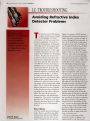
LCTROUBLESHOOTING
Avoiding RefractiveIndex
Detector Problems
he refractive index (RI) detector
is unique among common liquid
chromatography (LC) detectors becauseit is truly universal in its
detection capabilities. LC detectors
based on the absorbanceof ultraviolet
(UV) light are the most popular detectors becausethey are simple, reliable,
sensitive, and respond to a wide range
of sample compounds, but only if the
analytes have sufficient UV absorbance
to detect. Fluorescencedetectors are
much more selective and can be more
sensitive, but compounds must fluoresce to be detected. Mass spectrometry (MS) detectors are increasing in
popularity and can provide extremely
sensitive and selective detection, but
only if the sample can be ionized. RI
detectors respond to a universal, bulk
property of the analyte - its refractive index. Usually referred ro as differential refractiue index detectors, these
detectors detect peaks based on the
difference in refractive index between
the analyte and the background mobile
phase. This is a benefit that makes the
detector universal, but also a problem
in that the detector also is sensitive to
any other factor that affects refractive
index. The major factors are temperature, pressure, and mobile-phase
composition. This month's installment
describeshow RI detectors work and
discussessome good practices to follow
to get the most our of this powerful
detector.
How lt Works
tohn W. Dolan
LC Troubleshooting Editor
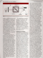
Let's first consider how the RI detector
works. There are specific design differences between detectors from different
manufacturers, but most have the elements of the generic detector shown in
Figure I in common. All RI detectors
depend on the fundamental property of
light's refraction, or change ofangle, as
it passesthrough different materials. In
the caseofthe RI detectot light passes
through the clear walls of the flow cell
and through the fluid in the cell. \7irh
each transition, refraction takes place
and the direction ofthe light changes
slightly. Rather than detect the absolute
refractive index (which some detecrors
can), most detectors measure the differential refraction between a sample flow
cell and a static reference cell filled with
mobile phase. This, in effect, subtracts
the mobile-phase background signal
from the sample signal. Becauselight of
longer wavelengths refracts more than
shorter wavelengths, a tungsten lamp or
Iight-emitting diode (LED) is used as
the light source in most RI detectors. In
a quick survey I did of commercial RI
detectors, various manufacturers used
light sources producing wavelengths of
660-880 nm. After the light has passed
through the sample and reference cells,
it must be detected, Most commonly
this is done with a pair of photodiodes.
As the refractive index changes, the
position ofthe light beam on the photodiodes shifts so that more or less light
shines on each diode. This shift of position can then be detected by comparing
the relative intensity of the signal produced by the two photodiodes. In Figure 1, you can see that most of the light
strikes the upper diode. \fith a change
in refractive index, the position ofrhe
light beam might move down, causing
less light to strike the upper diode and
more on the lower one.
The basic components bf the
RI detector shown in Figure I are
supplemented in real detectors by
1034 rcccNoRTH
ArvERrcA
voruMr30 NUI/BER
i2 DECEMBER
20i2
Referencecell
slit
r/
"..t"''i ,,i,.'"
'...:'^'{.
l:::::::::::
r:::::::::::
;,fi::
,f.lmffi
fm\
Lamp
\
\
S a m p l ec e l l
Detector
output
Figure 1: Schematicof a genericrefractiveindex detector,showing the key components.
hardware to stabilize the detector and
simplify operation. The reference cell
needs to be filled with mobile phase
of the same composition as that filling the sample cell (without the analyte, of course). To facilitate this, a
switching valve commonly is included
to direct mobile phase through the
reference cell to refresh or replace
the resident liquid. Becauseit can
take several hours for the detector to
stabilize, the switching valve may be
capable of routing the waste line back
into the mobile-phase reservoir to
allow the mobile phase to be recycled
during warm-up so as to reduce the
waste of mobile phase.
A change in environmental temperature can be a major problem with
RI detectors, because the refractive
index of a fluid is dependent on its
temperature. For this reason, RI
detectors are contained in an insulated compartment. Most commercial
detectors can control the temperature
above room temperature, typically
30-35 "C up to 50-60 "C, although
some models can cool the detector
as well. Also, the incoming mobile
phase must be at the same temperature as the thermostated portion of
the detector, so heat exchangers are
included to stabilize the temperature
of the mobile phase. Although flowcell volumes are relatively small, typically 8-10 pL, the heat exchanger
volume may be 5-10 times this, or
even more. This added volume means
that RI detectors usually generate
broader peaks than their UV counterparts with smaller total detector
volumes.
The inherent design and operating
principles ofRI detectors leave them
susceptible to several problem areas.
Specifically, anything that causes
changesin the temperature, pressure,
or mobile-phase composition will create
corresponding changes in the refractive
index of the mobile phaseas it passes
through the sample cell. If this is not
compensated by the static mobile phase
in the reference cell, baseline distur'We'll
look at each of
bances will occur.
these problem areas next.
Temperature Problems
As described above, the RI detector is
constructed to shield the detector cell
from external changesin temperature,
both through use of a thermostated
cabinet and a heat exchanger for the
incoming solvent. However, both of
these features are compromises between
effectivenessand expense.The cabinet
cannot protect against all environmental temperature changes,so it may be
necessaryto take additional action to
protect the instrument from local environmental temperature fluctuations.
Although the laboratory temperature
control may be quite good, at least as
indicated by the thermostat on the
wall, the local temperature may vary.
Perhaps a heating vent blows hot or
cold air directly at the instrument or
ratory I
r^:;:: :;*
",.,r;;:"*;';::
built a cabinet around the LC system
to shield it from local temperature fluctuations. It may be necessaryto move
the instruinent to another location
with better temperature control.
The heat exchangert job is to change
the temperature of the incoming mobile
phase to match that of the solvent in the
detector cell. Becausethe heat exchanger
adds extracolumn dead volume to the
system, it is a compromise between efficiency of temperature adjustment and
minimizing extra volume. To minimize
the temperature adjustment requirements, a column oven should be used
and set to the same temperature as the
detector (or vice versa) so that little or
no temperature change is necessary.
Also, be sure to insulate the tubing that
connects the column to the detector.
Some detectors come with insulated
connecting tubing, but a simple homemade insulator cair be made by slipping
a piece of heavy-walled plastic or rubber
tubing over the connecting tubing.
It may take several hours for the
detector to warm up and equilibrate
with the column temperature, so most
RI detectors are equipped with a valve
that can divert the waste stream back
into the mobile-phase reservoir. In
this manner, the mobile phase can be
recycled and the system can be left
with the flow on for several hours to
warm up or left pumping continuously,
'S?'hen
so it is always ready to use.
samplesare run, the valve is switched
so that the solvent from the detector is
directed to waste. Ifyou do recycle the
mobile phase, be sure to replace it once
in awhile. For a mobile phase that has
more than approximately 70o/obuffer
or aqueous component, I recommend
changing the mobile phase once a
'When
week.
the mobile phase contains
at least 30o/o organic solvent it can be
direct sunlight may cause local warming of the laboratory. In some laboratories, a different temperature is main-
used longer, but it should be replaced
every few weeks. Mobile phase that is
used for too long can gradually change
composition becauseof evaporation
of a more volatile component or may
grow bacteria that can block frits in the
tained at night than in the daytime.
Any of these factors can result in a
change in the temperature of the local
environment. You may need to block a
heater vent or redirect it. In one labo-
system. Be sure to replace the reservoir
with a clean one instead of refilling the
reservoir to prevent passing any contaminants from the previous batch of
mobile phase on to the new one.
www. chtrom atog r ap hyon I i ne.com
1035 IcGc NORTH
AMERICA
VOTUME
30 NUITBER
]2 DECEMBER
2012
Temperature-relatedproblems usually
show up as baselinedrift. Depending
on the magnitude of the temperature
change and the sensitivity setting on the
detector,this may be a gradually sloping or steeplysloping baseline.lVhen
baselinedrift is a problem, review the
preventivestepslisted above and seeif
there is something you can modify to
reduce the oroblem.
ing properly, then purge the pump to
releaseany trapped bubbles and resume
operation. Check-valve sonication in
methanol for a few minutes often will
clean a dirty or sticking check valve, or
the check valve can be replaced. Pump
seal replacement is a little more work,
Pressure Problems
Mobile-Phase Problems
Any change in the chemical composition of the mobile phase will change its
refractive index, as will the presenceof
dissolved air in the mobile phase. For
these reasons,RI detectors are always
operated only in the isocratic (not
but is something that can be done by
following the instructions in the pump
service manual.
when changing the solvent; drift is
common during solvent changeover,
so a nondrifting baseline is a good
indicator of column equilibration
with RI detection. As mentioned
above, be sure to change the mobile
phase regularly to avoid problems
with microbial growth, especially in
highly aqueous mobile phases.
Additional
A second factor that affects refractive index is pressure.For the quietest
baselines,the pressurein the flow cell
needs to be constant. Most RI flow
cells have an upper pressurelimit of
no more than approximately 100 psi
(7 bar), and the use ofa back-pressure
restrictor after the cell is common. A
back-pressurerestrictor can be thought
ofas a spring-loaded check valve that
maintains a fixed pressur€,such as 75
psi (5 bar), at all times. This will keep
the pressureconstant and also will
keep the system from exceeding the
maximum cell pressure,A piece of capillary tubing after the flow cell also can
function as a back-pressurerestrictor,
but the pressurewill be related to the
flow rate - ifthe flow rate is inadvertently set too high, a capillary restrictor
may cause the permissible cell pressure
to be exceeded.
BecauseLC systemsare operated
in a constant-flow mode, the pressure
should be constant. This usually is the
case,but problems with the pumps
can causethe pressureto fluctuate sufficiently that the baseline is disturbed,
even though other problems such as
retention-time shifts are not observed.
Pressureproblems becauseof pump
malfunctions often will create cycling
baselines.To confirm this, you can
change the flow rate and the frequency
ofthe baseline cycle should change in
accordance to the flow-rate change. ,
For example, a change from I mL/
min to 2 mL/min should double the
frequency of the baseline cycle. Common sourcesof pressurefluctuations
are faulty check valves, leaky pump
seals,air bubbles in the pump, and
more rarely a broken pump piston.
The easiestthings to check are bubbles
in the pump and degassingproblems
- make sure the deqasseris work-
gradient) mode and the mobile phase
must be thoroughly degassed.If you
have an inJine degasser,as is the case
for most LC systemstoday, be sure to
use it. Otherwise, helium sparging is
suggestedto degas the mobile phase.
Becauseof the extreme sensitivity of
the detector to very small changes in
refractive index, onJine mixing of
the mobile phase usually will create
problems. As a result, mobile phases
must be hand-mixed so that no change
in mobile phasecomposition occurs
within the LC system. It is best to use
the mobile phase as the injection solvent so the refractive index change at
the column dead-time is minimized.
Remember that the RI detector
measures the difference in refractive index between the contents of
the sample and reference cells, so
the reference cell needs to be purged
with fresh mobile phase whenever the
mobile phase is changed or replaced
with a fresh batch. It is a good idea
to purg€ the reference cell daily
to ensure its contents are matched
with the mobile phase exiting the
column. \flhen changing from one
mobile phase to another or washing
the mobile phase into a new column,
complete equilibration may take
longer than you normally allow with
UV detection. \fith UV and most
other detectors,allowing 10 column
volumes of mobile phase (=lJ mL for
a 150 mm X 4.6 mm column) to pass
through the column is sufficient for
equilibration. It may take longer with
the RI detector. \fatch the baseline
Comments
Sometimes RI detectors are used for
different applications with either aqueous and nonaqueous solvents.'When
this is the practice, be sure to flush
the entire system (reservoirs, degasser,
pump, autosampler, and detector) with
a series of solvents that are mutually
miscible. For example, go from aqueous solvents to l00o/o acetonitrile or
methanol, then to organic solvents.
Ifyou are not sure ofthe history of
the system, remove the column and
replace it with a piece of capillary
tubing. Then flush the entire system
with 20-30 mL of isopropanol, which
is miscible with both aqueous and
organic solvents. Then flush to the
desired mobile phase.
Baseline noise can be a critical factor with RI detection. Because RI
inherently has poor sensitivity when
compared to UV or other detectors,
signal-to-noise can be a limiting factor. For this reason, you may want
to take advantage of larger detector
tim€ constants (noise filters) with RI
than with other detectors. A good rule
of thumb is to set the detector time
constant at 10o/oof the peak width
at baseline or 200/oof the half-height
width. For example, if the peak is 10 s
wide at the baseline, you can use a 1 s
time constant. A higher time constant
value smoothes the baseline. but too
high a value will "smooth" off the top
of the peaks, making them broader
and shorter.
If you are having a hard time
distinguishing the source of a baseline problem between the pump
and mobile phase as opposed to a
temperature-relatedproblem, turn off
the pump (or set the flow to 0 mL/
min). This will eliminate the pump
or mobile-phase problem. If the baseline problem persists,it is becauseof
changing temperature.
voLut\,4E
30NUMBER
t2 1037
DECEMBER
2012tcccNoRTH
AtvtERtcA
www, chro m atog ra p hyo n I i n e,co m
Becauseof its extreme sensitivity to
temperature, a byword for RI detection is patience. It will take longer
to equilibrate the mobile phase, to
warm up the detector, or settle down
from any system change. For this
reason, if time is critical, it is prudent
to leave the detector turned on and
in a mobile-phase recycle mode. You
can reduce the flow rate under these
conditions, if you desire, but this will
leave the system in a standby mode
that will return rapidly to normal
And if all elsefails . . . read the directions! If you are a normal user of other
detectors,such as UV fluorescence,or
MS, troubleshooting RI problems may
operation.
Ifyou are looking for alternatives to
the RI detector for universal detection,
consider evaporative light scattering
detection (ELSD) or charged-aerosol
detection (CAD). Both of these detectors rely on evaporation of the mobile
phase and then detection ofthe "dust"
that is left behind. Both ELSD and
CAD can be operated with gradients,
which is an additional advantage, but
they are restricted to mobile phases
that are volatile - so no phosphate
Users Group at Linkedln
(www.linkedin.com).
buffer is allowed.
not be second nature. Consult the operation and service manual for your specific detector for troubleshooting and
preventive mai ntenance instrucrions.
Ifyou'd like advice from other users
regarding specific problems, consult one
ofthe on-line discussiongroups, such as
Chromatography Forum
(www. chromforum.org) or the HPLC
Erratum
Equation 2 of the October 2012 installment (8. Alsehli and J.\7. Dolan, LCGC
North Amer.10[30], 898-902 Q0l2l)
contained an error and should have read
as follows:
*=4txllf/2
'With
t2)
this change, all the calculated
values of peak widths and recommended
injection volumesshould be increased
fourfold. The discussion and conclusions
are still valid. For a fully corrected
vetsion, see
www.chromatographyonline.com/
Dolan1012
JohnW. Dolan
"LCTroubleshooting"
Editorlohn Dolan has
beenwriting "LCTroubleshooting"for LCGC
for more than 25 years.
One of the industry's
most respectedprofessionals,John is currently
the Vice Presidentof
and a principalinstructor for LC Resources,
Walnut Creek,California.He is alsoa
memberof LCGC's
editorial advisoryboard.
Directcorrespondence
about this column via
e-mail to [email protected].