1
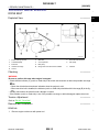
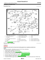
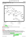
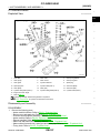
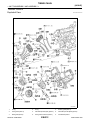
REAR TIMING CHAIN CASE
[VQ35HR]
< UNIT DISASSEMBLY AND ASSEMBLY >
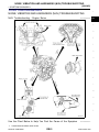
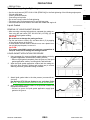
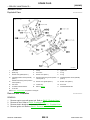
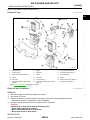
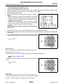
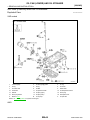
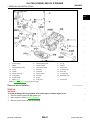
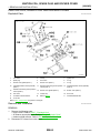
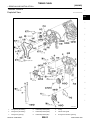
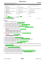
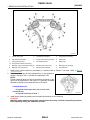
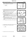
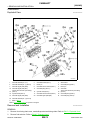
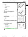
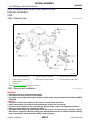
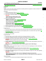
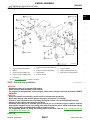
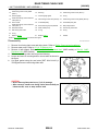
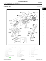
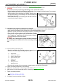
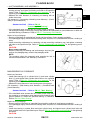
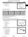
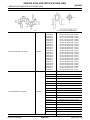
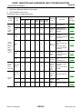
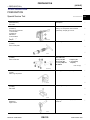
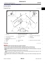
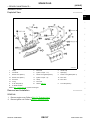
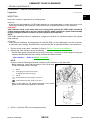
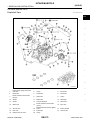
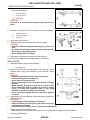
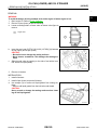
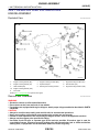
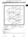
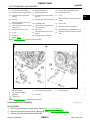
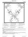
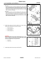
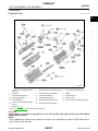
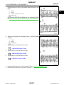
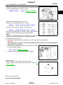
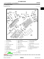
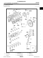
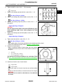
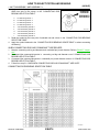
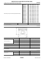
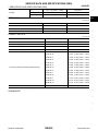
10. Slack guide
11. Crankshaft sprocket
12. Camshaft sprocket (INT)
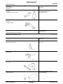
Valve timing control cover gasket
13.
(bank 1)
14. Seal ring
15. Valve timing control cover (bank 1)
16. Oil level gauge
17. Oil level gauge guide
18. O-ring
19.
Intake valve timing control solenoid
valve (bank 2)
20. Valve timing control cover (bank 2) 21. Valve timing control cover gasket (bank 2)
22. Front oil seal
23. Crankshaft pulley
24. Crankshaft pulley bolt
Intake valve timing control solenoid
25.
valve (bank 1)
26. Power steering oil pump bracket
27. Idler pulley bracket
28. Alternator bracket
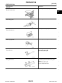
29. Water outlet (front)
30. Front timing chain case
31. Rear timing chain case
32. O-ring
33. O-ring
B.
C.
34. O-ring
A.
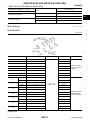
Refer to EM-97
Refer to EM-54
Oil filter
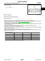
Refer to GI-4, "Components" for symbols in the figure.
Disassembly
1.
2.
3.
4.
a.
b.
INFOID:0000000003887378
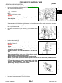
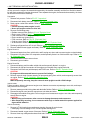
Remove front timing chain case and timing chain. Refer to EM-54, "Removal and Installation".
Remove water pump. Refer to CO-19, "Exploded View".
Remove oil pan (upper). Refer to EM-100, "2WD : Exploded View" (2WD models) or EM-103, "AWD :
Exploded View" (AWD models).
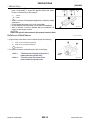
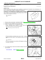
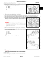
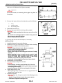
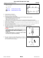
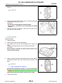
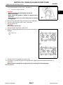
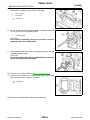
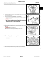
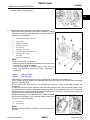
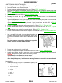
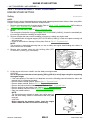
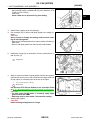
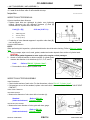
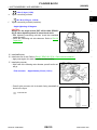
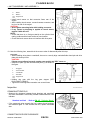
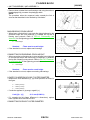
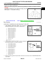
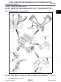
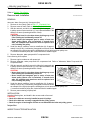
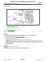
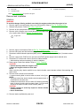
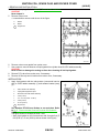
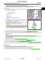
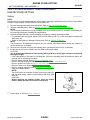
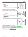
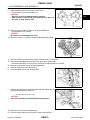
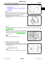
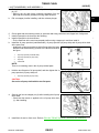
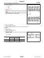
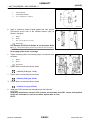
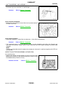
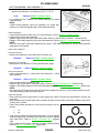
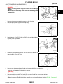
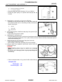
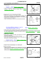
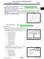
Remove rear timing chain case as per the following:
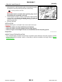
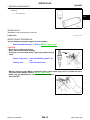
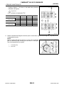
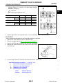
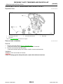
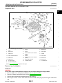
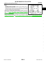
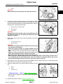
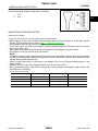
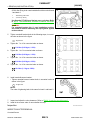
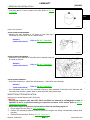
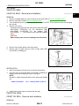
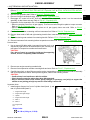
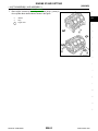
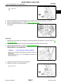
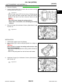
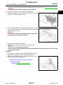
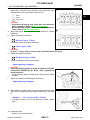
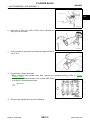
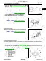
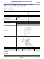
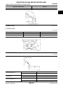
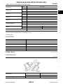
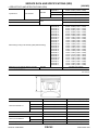
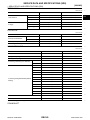
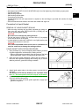
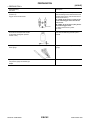
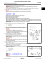
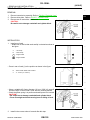
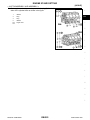
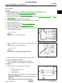
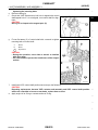
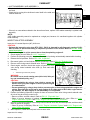
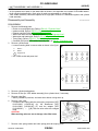
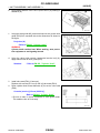
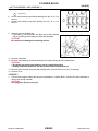
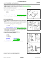
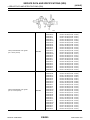
Loosen and remove mounting bolts in reverse order as shown in
the figure.
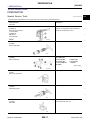
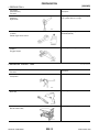
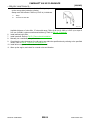
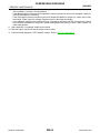
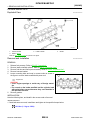
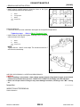
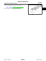
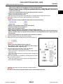
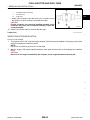
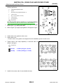
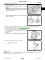
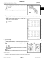
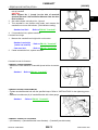
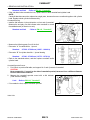
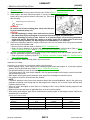
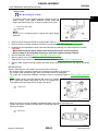
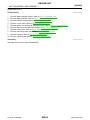
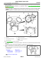
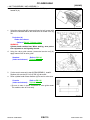
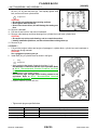
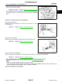
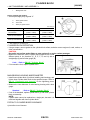
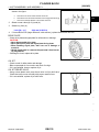
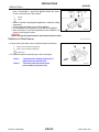
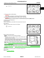
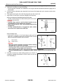
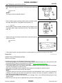
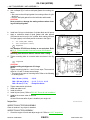
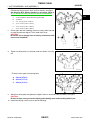
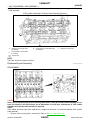
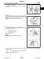
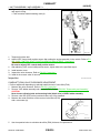
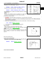
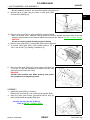
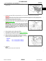
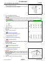
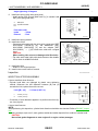
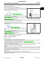
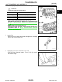
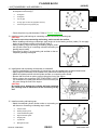
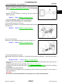
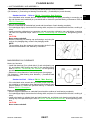
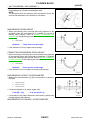
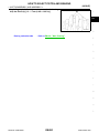
Cut liquid gasket using the seal cutter [SST: KV10111100 (J37228)] and remove rear timing chain case.
JPBIA0089ZZ
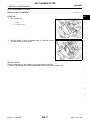
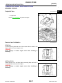
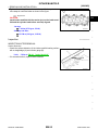
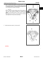
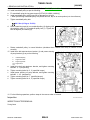
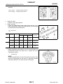
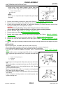
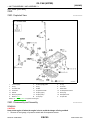
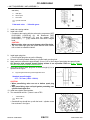
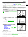
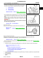
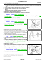
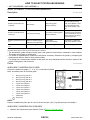
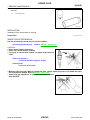
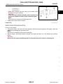
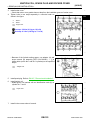
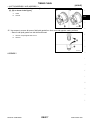
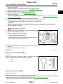
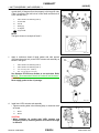
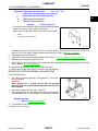
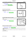
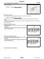
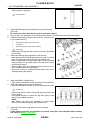
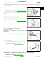
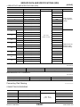
CAUTION:
• Never remove plate metal cover (1) of oil passage.
• After removal, handle rear timing chain case carefully so
it does not tilt, cant, or warp under a load.
JPBIA0088ZZ
Revision: 2009 March
EM-96
2009 FX35/FX50