1
I~
• • !"
Setting Up the Logic Analyzer
HP 1650A/51A Logic Analyzers
rh~ HEWLETT
a.:e..
PACKARD
@ Copynght Hewlett-Packard Company 1987
Pnnted in U.s A June 1987
..
About
this book ...
Introduction
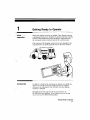
The purpose of this guide is to tell you how to prepare your logic
analyzer for operation. In this guide you will learn how to install
the operating system flexible disc, turn on the logic analyzer, and
connect the probe cables and a printer
You should read this guide if this is your first experience with the
HP 1650Al51A logic analyzers
Chapter 1 covers everything you need to know to get your logic
analyzer ready for power-up.
Chapter 2 shows you how to load the operating system, turn on the
logic analyzer and set the intensity of the display
Chapter 3 introduces you to the new probes and shows you how to
connect them.
Chapter 4 shows you how to connect your logic analyzer's RS-232C
interface bus to other equipment like a printer.
Once you have the logic analyzer up and running, you will want to
read the Getting Started Guide. It explains the basic operation of
your logic analyzer"
Table of Contents
~")-------------.,
Introduction
Chapter 1:
Getting Ready 10 Operate
I-I
Initial Inspection
1-1
Accessories
1-3 Probe Assembly Identification
1-4
Removing Yellow Shipping Disc
1-5
1·6
1-7
1-7
1-7
Selecting the Line Voltage
Checking for the Correct Fuse
Gettmg Power to the Instrument
Operating Environment
VentIlation
Chapter 2:
Turning on the Instrnment
2-[
2-2
2-3
2-3
2-4
Loading the Operating System
Installing the Operating System Disc
Line Switch
Intensity Control
Power-up Self-Test
Table of Contents (Continued)
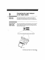
Chapter 3:
Connecting the Logic Analyzer to the Target System
3-1 Probes and Probe Pods
3-1 Connecting Pod Cables to the Logic Analyzer
3-2 Connecting Pods to Probe Cables
3-3 Disconnecting Probes from Pods
3-4 Connecting Grabbers to Probes
3-4 Connecting Grabbers to Test Points
3-5 Pod Grounds
3-5
3-6
Probe Grounds
Labeling Pods, Probes, and Cables
3-7
3-7
Signal Line Loading
Probe Interface
It
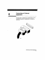
Chapter 4:
Connecting to External Equipment
4-2
Connecting the Logic Analyzer to a Prmter
@
Chapter 5:
What's Next?
1
Getting Ready to Operate
)
Initial., .
Inspection
Inspect the shipping container for damage [f the shippmg container
or packagmg materials are damaged, you should keep them until the
contents of the shipment have been checked for completeness and
the instrument has been checked mechanically and electrically
If the contents of the ahtpping container have been damaged or the
instrument does not operate properly, refer to the service manual
II
fXlOfllllQWtl
®ELIVER~ ~
I
I
Accessories
In addition to checking the instrument for damage. you should also
check to see that the accessories supplied with It are complete"
Accessones can sometimes be lost in transit when the shippmg
container is damaged
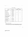
The table on the next page lists all the accessories for the
HP 1650Al51A logic analyzers. If any of these items are missing,
contact your nearest Hewlett-Packard office.
Getting Ready to Operate
1·1
Table 1 Accessories
Accessory
HP Part No.
Quantity
HP1650A
HP 1651A
Probe assemblies
01650-61608
5
2
Probe cables
01650-61607
5
2
5959-0288
100
40
Ground leads (long]
01650-82102
5
2
Ground leads {short I
01650-82103
10
4
RS-232C Loop back adapter
01650-63202
1
1
Probe and probe cable
numbering label card
01650-94303
1
1
Note 2
1
1
Operating system disc
01650-13501
2
2
Operating and
Programming manual set
01650-90903
1
1
Service manual
01650-90901
1
1
Grabbers (Note 11
AC power cable
Notes:
L Package of 20 per part number.
2. The type of power cord you receive with your logic analyzer depends on your country. If you
need more information about power cords. refer to the HP 1650A'SlA Reference .ManuaL
~
Getting Ready 10 Operale
1-2
.. ..
~
!
I
Probe Assembly
Identification
The following illustration will help you Identify the varrous parts of
the probe assemblies. Chapter 3 explains how to connect and
disconnect the parts of this assembly.
.,
GROUND
LEAD 'L0i(GJ
(016513-821132)
<,
PROBE LEAD
(131650-621011
PROBE HOUSING
/
GROUND LEAD (SHORT)
{01650-452031
"'-''--,
(01650-82HI3)
/
\/\
PROBE ASSEMBLY
(01650-61608)
~-,
GRABBER
( 5959-0288]
lQTY. 20 PER PIN)
PROBE CABLE
(016511-61607f
1656/E113
Gelling Ready to Operate
1-3
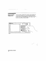
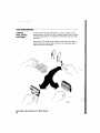
Removing Yellow
Shipping Disc
Your logic analyzer is shipped with a protective yellow shipping disc
m the disc drive" Before you can insert the operating system disc,
you must remove the yellow shipping disc Press the disc eject button
as shown in the figure. The yellow shipping disc will pop out part
way so you can pull it out of the disc drive
[i1]= :.__
I'
cErij!
I
"
~
~
8ErEi8 r~
<:
8888
EJ888b(L
888
~888
'-.-'
~888
808 CD .=J~
=-
I
l11M/UaII
_ • 'I
Getting Ready to Operate
1-4
~
"-( I
Selecling the
Line Voltage
~
I -
-
The line voltage selector has been factory set to the line voltage
used in your country. It is a good idea to check the setting of the
lme voltage selector so you can become familiar with what it looks
hke. If the setting needs to be changed, follow the procedure In the
next paragraph.
lou can damage the lOgIC analyzer if the module
set to the correct poeinon
18
not
You change the lme voltage setting by pulling the fuse module out
and reinserting it with the proper arrows aligned To remove the
fuse module, carefully pry at the top center of the module taa shown!
until you can grasp it and pull it out by hand
Gelling Ready to Operate
1·5
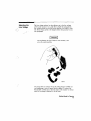
Checking for
the Correct Fuse
If you need to check for the correct (USf'S, remove the fuse module
and look at the amperage and voltage of each fuse The followmg
figure will help you locate the 115 V and 230 V fuses" To remove the
fuse module. carefully pry at the top center of the module las shown!
until you can grasp it and pull it out by hand" (Refer to "Selecting
the Line Voltage" on the previous page)
~~
~'"
r
115V
3.0 A FUSE
Gelling Ready to Operate
1-6
Getting Power to
the Instrument
The HP 1650Al51A comes with a a-wire power cable. When you
connect the cable to an AC appropriate power receptacle, a ground is
provided for the Instrument cabinet. The type of power cable you
receive with the instrument depends on your country.
I
WARNING
~
Th amid possible shock hazard. yuu must connect the
instrument to a properly grounded 3-wir€ receptacle.
Operating
Environment
You may operate your lOgIC analyzer III a normal lab or office
environment without any additional considerations, But don't block
its ventilation If you intend to use It in another type of
environment, you must not exceed certam limits" You can fmd these
Limits in the HP 1650A.i51A Reference :Manual.
Ventilation
You must provide an unrestricted airflow for the fan and ventilation
openings in the rear of the logic analyzer However, you may stack
the logic analyzer under, over, or m-between other instruments as
Long as the surfaces of the other instruments aren't needed for thenventilation
Getting Readv to Operate
1-7
2
Loading. theOperati'ng
System
Turning on the Instrument
Before you can operate the logic analyzer, it must transfer its
operating system from a disc to its memory. This IS called "loading
the operating system" or "booting."
The logic analyzer operating system is a set of instructions that
control the operation of the instrument. The operating system
resides on a Sfi-inch flexible disc YOll received two identical
operating system discs- You should mark one of them Master and
store It in a safe place Mark the other one Work and use only the
work copy This will provide you with a back-up in case your work
copy becomes corrupt.
To prevent damage to your operatmg system disc. DO
NOT remove the disc from the disc drive while it is
running On1)r remove it after the indicator light has
gone out.
Turning on the Inslrument
2-1
E1UiM&WWWU
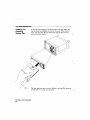
Installing the
Operating
System Disc
To load the logic analyzer's operating system, you must install the
disc as shown below before you turn on the power. When the dISC
snaps mto place. the disc eject button will pop out. Now you can
turn on t he logic analyzer
(
le~nle
The logic analyzer runs a series of self-tests and loads 'the -operating
system before it IS ready to be operated,
Turning on the Instrument
2-2
-------------------11
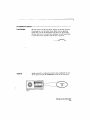
Line Switch
The line switch is on the rear panel You turn on the logic analyzer
by pressing the 1 on the rocker switch. Make sure the operating
system dISC is in the disc drive before you turn It on. If you forget
the dis-c. don't worry, you won't harm anything You will merely have
to repeat the turn-on procedure with the disc in the drive
Control
display intensity to a different level that's more comfortable for you.
You do this by turning the INTENSITY control on the rear panel
Turning on the Instrument
2·3
Power-up
Self-Test
When you turn on the logic analyzer, tt performs a senee of selftests. When it has successfully completed these tests. it loads the
operating system into memory from the disc.
~
I ' -
When the logic analyzer has completely Loaded the operating system,
it displays the System Configuration menu as shown below.
Note
This is tlie HP 1650A SJ"stem Format Specification menu.
If you ha~'e an HP 1651A, the only diflerence is pod 1 will
be essigned to analyzer 1 and pod 2 wIll be eesigned to
analyzer 2 There won't be any pods in the
UNASSIGNED area of the dIsplay
Turning on the Instrument
2-4
3
:0 Probes .and-
Connecting the Logic Analyzer
to the Target System
Probel>ods
Probes and probe pods allow you to connect the logic analyzer to
your target system. Each probe pod carrys 16 data channels, one
clock channel. one pod ground and two power lines for preprocessors.
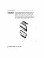
Connecting Pod
Cables to the
Logic Analyzer
iou connect the pod cables to the pod connectors on the real' panel of
the logic analyzer. The connectors are keyed for proper or-ientation.
You can connect either end of the cable to the rear panel since both
ends of the cables are alike"
Connecting Logic Analyzer to the Target System
3-1
¥F
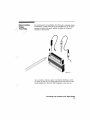
Connecting Pods
to Probe Cables
The pods of the HP 1650Al51A differ from the POdR in other logic
analyzers in that they are passIve (have no actrve circuits at the
outer end of the cable). The pods, 35 they will be referred to for
consistency, are the connector bodies tas shown below) that the
probes are installed in when you recerve your lOgIC analyzer.
To connect a pod to a cable, you align the key on the cable connector
with the slot on the pod connector and connect them the same way
you connected the other end to the logic analyzer.
leY/UII
Connecting Logic Analyzer to the Target System
3·2
..
~.
~I
)
Disconnecting
Probes
From Pods
You can disconnect un-used probes from the pods to eliminate clutter.
'Ib disconnect a probe, insert the tip of a ball-point pen in the latch
opening and push while gently pulling the probe out of the pod
connector as shown below
16SlVD'11
lou re-connect a probe to a pod by insertmg the double pin end of
the probe into the pnd. The probes and pod connector body are both
keyed rchamferedt so that they will fit together in only one way,
Connecting logic Analyzer to the Target System
3-3
Connecting
Grabbers
to Probes
You connect the grabbers to the probes by slipping the connector at
the end of the probe onto the recessed pin in the side of the grabber.
Connecting
Grabbers to
Test Points
The grabbers have a hook that fits around Ie pms and component
leads. You connect the grabber by pushing the rear of the grabber to
expose the hook. hooking the lead and releasing your thumb as
shown be low.
(
);
'~'
Connecting Logic Analyzer to the Target System
3-4
Pod Grounds
Each pod is grounded by a pod ground lead that should always be
used. You can connect the lead directly to a ground pin on your
target system or use a grabber. The grabber connects to the ground
lead the same way it connects to the probe lead.
'Ib connect the ground lead to grounded pins on your target system,
you must use 063 mm (0.025 inl square pins or round pins with a
diameter from 0.66 mm <0026 in) to 0,,84 fa.033 in).
Probe Grounds
You can ground the probes in one of two ways. You can ground them
with the pod ground only; however, the ground path won't be the
same length as the signal path through the probe" If your probe
ground path must be the same as your signal path, use the short
ground lead (probe ground), The probe ground lead connects to the
molded probe body via a pin and socket. You can then use a grabber
01' grounded pins on your target system the same way as the pod
ground.
If you need additional probe ground leads, order HP part number
01650-82103 from your nearest Hewlett-Packard sales office
Connecting Logic Analyzer to the Target System
3-5
fj
ills
Labeling
Pods, Probes
and Cables
So you can find the pods and probes you want to connect to your
target system, you need to be able to quickly identify them" Included
with your logic analyzer are self-adhesive labels for each pod, cable
and probe.
They come In sets Each set has labels for each end of the cable-a
label for the pod connector body, a label for the clock probe and 15
labels for each of the channels
--3"
,/
/
Connecting logic Analyzer to the Target System
3-6
J,
'~#
Signal Line
Loading
~ ~
Probe
Interface
,
Any signal line to be connected to a probe must be able to supply a
minimum of 600 mV to the probe tip, which has an input impedance
of 100 kf shunted by 8 pF. If the signal line can't supply this
voltage, you will not only get an mcorrect measurement but the
system-under-test may also malfunction
Instead of connecting the probe tips directly to the signal lmes, you
may use the HP 10269C Probe Interface (optional accessory). It
allows you to connect the pod cables (without the probes) to
connectors on the interface, When the appropriate preprocessor IS
installed in the interface, you will be able to connect the interface
directly to the microprocessor-under-test. A number of microprocessor
specific preprocessors are available as optional accessories You will
find them listed in the HP 1650A/51A Reference Manual along WIth
additional details on how the probe interface and preprocessors work.
Connecting logic Analyzer to the Target System
3·7
4
Connecting to External
Equipment
Your logic analyzer is equipped with a standard RS-232C mterface,
which allows you to connect the logic analyzer to a printer or
controller. The connector is a standard 25 pin "D" connector as
shown below.
Connecting to External Equipment
4-1
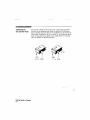
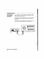
Connecting the
Logic Analyzer
to a Printer
You can connect a printer to the logic analyzer's RS·232C interface
when a controller isn't connected. The printer enables you to print
various data from the logic analyzer.
To connect the printer to the logic analyzer, use a standard RS·232C
cable UIP Model number 13242GI and make your connections as
shown below.
You will find the complete details of how to operate the printer with
the logic analyzer in the HP 1650A/51.4 Reference 1\!Ianual.
.
11 ~~~~~~~~~~~~~~~~
g·_--=fE
a
qp~
4·2
0
~~~~~~~~~~~~~~~~~~~~
~c::::::::=:::::~~~~
IHeIDII7
Connecting to Exlernal Equipment
a
~
5
What's Next?
Now that you have unpacked, inspected, and begun operating the
logic analyzer, the next step will depend on your needs, [f you are a
first-tame logic analyzer user who wanted to get the instrument
running before reading Feeling Comfortable with Logic Analyzers,
you should read it now. If you are familiar with logic analysis, read
either the Getting Started Guide or the HP 1650A,'51A Reierence
l\Jlanual-
In a task format the Getting Started Guide teaches you the bastes of
how to operate the front panel and configure it for task
measurementsThe HP 1650AiSlA Reference ~Manual describes all the front-panel
and programmmg functions of the logic analyzers Once you feel
comfortable with the basic operation of the front panel. use this
book
\,
What's Next?
5-1
()
r/ii!'- HEWLETT
a:r.JI PACKARD
5959--6012
PRINTED IN U.S.A.