1
Nikon®
Coolscan™
Installation and
Basic Operation
Guide
for
Macintosh™
Nikon®
ELECTRONIC IMAGING
(f)
Coolscan™ Installation and
Basic Operation Guide
for Macintosh™
FCC Radio Frequency Interference Statement for Coolscan
This equipment has been tested and found to comply with the limits for a class B digital
device, pursuant to Part 15 of the FCC Rules. These limits are designed to provide reasonable protection against harmful interference in a residential installation. This equipment generates, uses and can radiate radio frequency energy and, if not installed and used
in accordance with the instructions, may cause harmful interference to radio communications. However, there is no guarantee that interference will not occur in a particular
installation. If this equipment does cause harmful interference to radio or television reception, which can be determined by turning the equipment off and on, the user is encouraged to try to correct the interference by one or more of the following measures:
1. Reorient or relocate the receiving antenna.
2. Increase the separation berween the equipment and receiver.
3. Connect the equipment into an outlet on a circuit different from that to which the receiver
is connected.
4. Consult the.dealer or an experienced radio/TV technician for help.
Installation Safety Regulation of Coolscan Internal Model
This scanner has been approved by the Underwriters Laboratories, Inc., in the U.S., the
Canadian Standards Association, and as a class B device under Part 15 of the FCC
(Federal Communications Commission) Rules. This unit should only be installed in
equipment that has been approved according to the same standards.
AC Line Cord
Note that different power cords are needed for different line voltage. If the line voltage is
greater than 230V AC, the plug should be rated for 250V AC and 15A (NEMA 6P-15),
this cord insulation should be at least STY type, and the gauge of the cord should be at
least AWG 18. If the line voltage is 115V AC or less, the plug should be rated for 125V
AC and lOA with SVT type resistance for the cord insulation and a gauge of at least AWG
18, and the cord should meet the safety standards of the country where the unit is used.
When Taking this Product Out of the Country
The use of this product may violate local laws and restrictions in some countries. If this is the
case, Nikon can not bear any responsibility for any violations resulting from the use of this
product. Note that, in some countries, this product can be made to conform with regulations through an internal adjustment. Therefore, before taking this product out of the
country, consult with your Nikon service representative.
Page II
Nikon
CooLscan Installation Guide for Macintosh
Apple Disclaimer
T he following disclaimer is required by Apple Compurer, Inc. It applies only
to
Apple soft-
ware. All other software is covered by Niko n's limited warran ty.
"APPLE COMPUTER , INC. ("APPLE") MAKES NO WARRANTIES, EXPRESS OR IMPLIED, INCLUDING WITHOUT LIMITATION THE IMPLIED WARRANTIES OF MERCHANTABILITY AND FITNESS
FOR A PARTICULAR PURPOSE, REGARDING THE APPLE SOFTWARE.
APPLE DOES NOT WARRANT, GUARANTEE OR MAKE ANY REPRESENTATIONS REGARDING
THE USE OR THE RESULTS OF THE USE OF THE APPLE SOFTWARE IN TERMS OF ITS CORRECTNESS, ACCURACY, RELIABILITY, CURRENTNESS OR OTHERWISE. THE ENTIRE RISK AS
TO THE RESULTS AND PERFORMANCE OF THE APPLE SOFTWARE IS ASSUMED BY YOU . THE
EXCLUSION OF IMPLIED WARRANTIES IS NOT PERMITTED BY SOME STATES . THE ABOVE
EXCLUSION MAY NOT APPLY TO YOU . "IN NO EVENT WILL APPLE, ITS DIRECTORS , OFFICERS,
EMPLOYEES OR AGENTS BE LIABLE TO YOU FOR ANY CONSEQUENTIAL, INCIDENTAL OR
INDIRECT DAMAGES (INCLUDING DAMAGES FOR LOSS OF BUSINESS PROFITS, BUSINESS
INTERRUPTION, LOSS OF BUSINESS INFORMATION, AND THE LIKE) ARISING OUT OF THE USE
OR INABILITY TO USE THE APPLE SOFTWARE EVEN IF APPLE HAS BEEN ADVISED OF THE
POSSIBILITY OF SUCH DAMAGES. BECAUSE SOME STATES DO NOT ALLOW THE EXCLUSION
OR LIMITATION OF LIABILITY FOR CONSEQUENTIAL OR INCIDENTAL DAMAGES, THE ABOVE
LIMITATIONS MAY NOT APPLY TO YOU . APPLE'S LIABILITY TO YOU FOR ACTUAL DAMAGES
FROM ANY CAUSE WHATSOEVER , AND REGARDLESS OF THE FORM OF THE ACTION
(WHETHER IN CONTRACT, TORT (INCLUDING NEGLIGENCE), PRODUCT LIABILITY OR OTHERWISE,) WILL BE LIMITED TO $50."
Nikon
CooLscan Installation Guide for Macintosh
Page 111
Acknowledgments
Nikon acknowledges with gratitude the contributions of the Design, Planning and
Production Sections of the Electronic Image Engineering Division ofNikon Corp. and the
Marketing & Development Group at Nikon Electronic Imaging. Nikon Electronic Imaging
would also like to thank all those who helped test Coolscan and its software.
This manual may not, in whole or in part, be copied, photocopied, reproduced, translated,
or converted to any electronic or machine readable form without prior written consent of
Nikon Inc.
The accompanying 35mm slide is for instructional purposes only and may not be copied,
reproduced, translated, or converted to any electronic or machine readable form for any other
usage without prior wri((en consent. The slide is © 1993, John Harcourt.
Trademark Information
Coolscan TM, Nikon Co ntrol™, and Coolscan Control™ are trademarks of Nikon Inc.
Nikon LS-IOTM and Nikon LS-IOE™ are trademarks of Nikon Corporation.
ImageAccess™ is a trademark ofAXSIOpticai Technology Resource, Inc.
Fractal ColorStudio™ is a trademark of Fractal Design.
Photoshop TM is a trademark of Adobe Systems Inc.
Macintosh™, PowerBook™, HDI-30™, Quadra™, IIci™, IIfxTM, IIvx™, IIvi™,
Performa TM, Centris™, PowerMac™ and Quickdraw™ are trademarks of Apple Computer, Inc.
Centronics TM is a trademark of Centronics.
Microchannel™ is a trademark ofIBM.
PU™ is a trademark of Peripheral Land, Inc.
MS-DOSTM and Windows™ are trademarks of Microsoft Corp.
Syquest™ is a trademark ofSyquest Inc.
America Online™ is a trademark of America Online Inc.
PhotoStyler™ is a trademark of Aldus Corp.
Picture PublisherTM is a trademark of Micrografx, Inc.
CompuServe™ is a trademark ofCompuServe Inc.
Nikon Inc.
Electronic Imaging Department
1300 Walt Whitman Road
Melville, NY 11747
516-547-4355
© 1993, Nikon Inc. All rights reserved.
Printed in the United States of America
PageN
Nlkon
Coolscan Installation Guide for Macintosh
Table of Contents
Table of Contents
Chapter 1 - Introduction .................................................................................................. 1
Before You Begin ....... .......... ........... ...................... ...... ........................................ ....... 1
About this Manual ................ .. ..................... ......... .. ......... .... ........ .. .. ............... ........... 2
Unpacking ................................................................................................................. 3
Registration ............................. ................. ...... .. .... ..... ........ ......... ... ... ...... .................... 3
Software Installation ........ ... ..................... ................. .... ..... ... ...... .................... ............ 3
Minimum Macintosh System Requirements ............. ....... ........... ... ........................ ... .4
Suggested System Configurations ........................ ...... ....... ..... ............. .. ................. ... ..4
Chapter 2 - Setting Up Coolscan ......................................................................................7
The Front Panel ......................................................................................................... 7
Film Slot .............................. .................................... ..................... ... .................... 7
Focus Wheel ......................................................................................................... 7
Power/Busy/Error Indicator Light ... ....... .. .. ...................... ..... .. ... ... ... .................... 8
The Rear Panel- LS-I0E ........................ .... ....................................................... ... ..... 8
The Rear Panel- LS-I0 ............................................................... .. ....... .... .... ............. 9
Orientation and Placement of the LS-lOE ................................................................ 10
Proper Orientation ......................................................................... ......... ...... ..... 10
Proper Placement .............. .................................... .................. .. ........ .. ............ ... 11
Transporting Coolscan ............................................................................................. 11
Connecting AC Power to the LS-lOE .................. :........ .... ...................................... . 12
Safety Precautions When Connecting AC Power to the LS-l OE .. ............................ 12
AC Power Safety Precautions - LS-lOE .................................................................... 13
Installation Precautions .. ...... .... ..... .... .. ...... ..... ....... ..... ... ...... ............................ ......... 13
General Safety Precautions .......... ......... ............ .. ............................. ..... ..... .. .. .. ... ...... 14
Operation Precautions ............ ................... ....... ..... ............... .. .................................. 14
Chapter 3 - The SCSI Interface ...................................................................................... 15
System Requirements for SCSI Installation .............. ................................................ 15
Setting the SCSI ID ........... .................... ... ... .... ....... .... ............................. ...... ..... ..... 15
Determining Which SCSI ID Number to Use .................................................... 16
Setting the SCSI ID - LS-I OE ........... ................. ................................................ 17
Setting the SCSI ID - LS-I 0 .............................................................................. 17
Terminating the SCSI Chain ................................................................................... 18
Terminating the LS-l OE ..... ........ ....................... .... ......... ........ .... ... ... .. .. .............. 19
Termination Power ........................................................... ......... .. ... ..... ........ . 19
Terminating the LS-I0 .......... .................................................... .........................20
SCSI Cables ............................................................................................................. 20
SCSI Cables Used With the LS-lOE ......... ........... ....... ................ ........................ 20
SCSI Cables Used With the LS-I0 ..................................................................... 21
Nlkon
Coolscan Installation Guide for Macintosh
Page V
Table of Contents
The Macintosh's External SCSI Connector ..... .................................................. .. .. ... 23
The MacintOsh's Internal SCSI ConnectOr ..... .. ................................. .... ...... ............. 23
Connecting to the Internal SCSI Connector .... .......... .. .. ..................................... 24
The SCSI Chain ............ ........... ............ ......... ... ..... ... .. .............................................. 25
Setting U p the SCSI Chain - LS-10E .................................................. .. .................. 25
Connecting Two SCSI Devices .............. .. .......................................................... 26
Connecting M ultiple SCSI Devices .................................................................... 27
Setting Up the SCSI Chain - LS- 10 ......................................................................... 28
Connecting Two SCSI Devices ............... ... .. ..... ...... .... ........... .. ..... .............. ... .. .. 28
Connecting M ul tiple SCSI Devices .. .. .. .. .. .... .. .. .. .... .... .... .. .... .. .. .. .... .................... 29
Important Information About the SCSI Interface ....................................... .. ........... 30
Chapter 4 - Basic Operation .......................................................................................... .33
Introduction ..... .. ..... ................................................................................................. 33
Fil m ...... ........ .... .......... ............ ....... .... .... ... ...... ... ..... .... .. .. .. ... .. ....... .. .. ... .... ... ... .. ... .. ... 33
Slide Mounts ................................. .... ........... ...... ....... ............... ......... ....... .... ........ .... 35
Handli ng the Film ............. .. ... .......... .... ........ .... .. ...... .... .... .. ... ... ... ... ... .. ... .... .. ... ...... .. 36
Dust Removal .......................................... ... ................ ...... ...... ..... .. .... .. ....... .... ... .36
Stai n and Fingerprint Removal ..................... .. .. ............ ....... ..... .. .... .. .... .. .... .. ...... 36
Hiding Scratches ........................................ ............... ... .. ........ ......... ..... ... .... ... .... 37
Finding the Emulsion Side of the Film ............ .. .. .. .... .. .... .. .......... .. .... .. ........ .. .... .. .... .37
Slide Orientation .... .... ................................ .............................................................. 38
Inserting Slides ... .. ..... .. ...................................... ............ ..................... .... .................. 41
Inserting Portrait Orientation Slides .................................................................. .41
Inserting Landscape Orientation Slides .............................................................. .41
Ejecti ng Slides .... ........ .. ...... .... .. ..... .. ................................................. .................... ... .42
T he Film Strip Holder ............................... ... ... ...... ... .............. .. ........ .... ... ......... ... .. .. 43
Pos itioning the Film in the Holder ..................................................................... 44
Inserti ng the Film Strip Holder in the Scanner ... ...... .. ... .. .... ............ ............... .. .. 46
Removing the Film Strip Holder ........................................................................ 47
Focus ....... ..... .. ............................ ..... ...... ... ... .... .... .... ....... ...... .... .... ..... ...... ..... ... ....... .47
Thickness of the Slide Mount .. .................... ........... .. .................... .. ............ .. ...... 47
T he Mount Type ..... ...... .. ... ... ............ ... .. ..... ......... ..... ... .... ..... ..... ....................... .48
The Film Location in a Mount ........................................................................... 48
Emulsion Side of the Film .................................................................................. 49
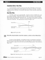
Non-flat Film ........................ ........................ ..................................................... 49
T he Focus Wheel ......... .. .. ......... ... ... ................ ..... ... ............. ... ......... ..... .. ... .. ... ......... 50
Cal ibration ........ ...... .. ............. ........................ .......................................................... 50
Troubleshooting .............................................................................................................. 51
General Problems ...... ..... ... ... .... .. ... .. .... ......... .. .... .. .. .... .. ..... .. .... ... .. ... ...... ..... ...... ......... 53
Macintosh-Specific Problems ........................................................... ................. ....... .55
Page VI
Nikon
Coolscan Installation Guide for Macintosh
Chapter 1
Introduction
Introduction
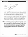
Thank you for purchasing the Nikon Coolscan TM 35mm Film Scanner, and welcome to our family of electronic imaging products. We are confident that Coolscan will
meet and exceed the high standard of quality, reliability, innovative design, and ease of
use which you have come to expect from Nikon.
Before proceeding, make sure that you have read the Open Me First documents
enclosed with Coolscan, including a packing Check List and important operator safety
precautions.
Before You Begin
The installation procedures for Coolscan are straightforward. The instructions
provided in this manual will lead you through these procedures and have you scanning
within an hour. However, if you are not comfortable mounting hardware into your
compurer, please contact a qualified service person to assist in the installation of your
scanner.
There are two models of Coolscan. The first is the IS-I0 internal model, which is
mounted into your computer just like a floppy disk drive. The other is the IS-I0E
external model, which is a peripheral device and cannot be mounted into your computer. As you follow the installation procedures in this guide, refer only to the sections
which are appropriate to the Coolscan model you have purchased. In this guide, the
Coolscan internal model will always be referred to as "LS-l 0." The Coolscan external
model will always be referred to as "LS-I0E," in which the "E" designates "external. " If
you are unsure of which model you are installing, refer to the sticker on the base of the
scanner, which will indicate either "LS-l 0" or "LS-l OE."
At the time of this printing, optional mounting kits for the LS-l 0 are available
from Nikon Authorized Resellers for the following Macintosh CPU's only.
• Quadra 900/950
• PowerMac 7100
• Quadra 650 (formerly the Centris 650)
· IIvx
• Performa 600
• IIvi
Nikon
CooLscan Installation Guide for Macintosh
Page 1
Introduction
Chapter 1
These mounting kits include faceplate bezel, mounting bracket(s), cables and
installation instructions for the particular model you wish to match.
The LS-1O can be mounted in any available 5-114" half-height drive bay of the
CPU's listed above. Please consult the installation instructions enclosed with the
mounting kit for your particular cpu. Note that mounting kits for other Macintosh
CPU's may be available from third-party suppliers. Typically, these are for internal hard
disk installations. These may be suitable for LS-l 0 installations. Consult with your
Nikon Authorized Reseller or Nikon Electronic Imaging to help make this determination.
Due to the presence of metallic shielding material, it is not currendy possible to
mount the LS-IO in the Macintosh Quadra 800/840av without completely removing the CPU's front faceplate. Custom solutions might be provided by some tbirdparty companies, but are not available at the time of this printing.
About this Manual
The function of this manual is to provide both the novice and expert user with
information to successfully install Coolscan. A complete description of scanner hardware installation and scanner software installation is provided.
Very important informational items are printed in boldfaced type with a
triangular alert icon located in the margin.
Following is a summary of the contents of this manual:
Chapter One - Introduction· (this chapter) Provides an overview of the
Coolscan documentation package, product registration information, system requirements, and information on backing up the software.
Chapter Two - Setting Up Coolscan • Describes how to set up the scanner,
where to place the scanner, transporting the scanner, and safety notes regarding the
usage and installation of the scanner.
Chapter Three - The SCSI Interface • Describes the SCSI Interface, including
setting up the SCSI ID, terminating the SCSI bus, how to connect to the computer
SCSI bus, the SCSI chain, and a general description of the pro's and con's of the SCSI
bus.
Chapter Four - Basic Operation • Covers the fundamentals of 35mm film, slide
mounts, film handling, proper insertion of film in Coolscan, and use of the film strip
holder.
Page 2
Nikon
Coolscan Installation Guide for Macintosh
Chapter 1
Introduction
Troubleshooting • Solutions to problems you may encounter in installing and
operating your Coolscan.
Unpacking
Again, if you have not done so already, please review the Open Me Firstdocuments enclosed with your Coolscan before proceeding in this manual.
Welcome back!
By this point you have:
1. Removed all packaging materials from the scanner and the interface kit.
2. Confirmed that you have received all the parts that you were supposed to by using
the packing Check List.
3. Checked for damage to the scanner caused by shipping. If you noticed any damage, you have notified the authorized Nikon reseller from whom you purchased the
scanner.
4. Saved all shipping and packaging materials in case you need to ship the scanner in
the future.
Registration
Completing and returning the enclosed Product Warranty Registration Card is
very important to you. It is the only way that we can ensure that you promptly receive
the latest information and software updates from Nikon. We feel that it is so important
that we are offering an added incentive - upon receipt of your completed card, we will
send you Nikon's Guide to Scanning, free of charge! This is an invaluable comprehensive
manual on scanning and color reproduction. So, please complete the Product Warranty
Registration Card and mail it today!
Software Installation
Installation of the Nikon scanning software accompanying Coolscan is covered in
detail in the companion user manual Software Reference for Scanners. As is the practice
with any software, it is strongly advised that you make a complete backup of the
enclosed distribution software diskette and store the original master diskette in a safe
place. Always work with the backup copies when installing the Nikon software.
Nlkon Coolscan Installation Guide for Macintosh
Page 3
Introduction
Chapter 1
Minimum Macintosh System Requirements
As an absolute minimum, your Macintosh computer system must be configured
with the following components:
• Macintosh family of computers with SCSI interface
• Macintosh System 6.0.5 or later
• 32-bit Quickdraw (when using models preceding Macintosh IIci)
• 8 Megabytes of RAM (more recommended)
• 80 Megabyte Hard Disk (300 MB or more recommended)
• 8-bit display (24-bit true-color display strongly recommended)
Suggested System Configurations
Following these suggestions will yield the best scanning results:
• Set your disk cache (found in the "Memory" Control Panel in System 7, and in the
Control Panel in System 6) to the minimum setting, as scan times increase if the
RAM cache is set above the minimum. Most imaging applications, including Nikon
Control, have their own method for dealing with images larger then available RAM.
• Virtual Memory, also in the "Memory" Control Panel in System 7, should be
switched off.
• File Sharing should be switched off. Any extended background operation, such as
copying large files from your system to another over a network, may cause Coolscan
to 'time out' during operation.
• Allocate at least 80% of your available memory to the application that is hosting
the Nikon Scanner plug-in (see your Macintosh User's Guide if you are are not
familiar with this procedure) . Nikon Control requires a minimum of 4 megabytes
of RAM to operate. Adding memory to your system is one of the best investments
you can make to increase overall performance.
• Coolscan will only operate from the SCSI controller that is part of the main logic
board, also referred to as the 'motherboard.' Do not connect Coolscan to any thirdparry SCSI controller in an attempt to increase your scanning speed. Nikon's
Marketing & Development Group is working with a number of third-parry vendors
to gain compatibiliry with such controllers. The limiting factor is the rate of data
Page 4
Nikon
Coolscan Installation Guidefor Macintosh
Chapter 1
Introduction
delivered by Coolscan, not the rate that the SCSI controller card can accept data.
The Nikon Scanner plug-in software will not find Coolscan unless it is connected to
the main SCSI bus.
• For the most pleasing display, set yo ur "Monitors" Control Panel to the maximum
number of co lors available. "Thousands" or "Millions" of colors will provide an
excellent display of yo ur image. If your system only supports a maximum of256
colors you will see a 'dithered' image, which looks grainy or speckled. The monitor
setting has no effect on the actual quality of your image, which is always captured in
24-bit mode (16.7 million colors) .
• Color images can occupy large amounts of disk space. So, make sure your hard
disk has sufficient free space to store the images yo u plan to scan. You should have
at least 60 megabytes of free space available if yo u plan on maximum resolution
scans.
Nikon
Coolscan Installation Guide for Macintosh
Page 5
Introduction
Page 6
Chapter 1
Nlkon
Coolscan Installation Guide for Macintosh
Chapter 2
Setting Up Cooiscan
Setting Up Cooiscan
This chapter will introduce you to the main components of the LS-l 0 and LSIOE models, proper placement of the LS-I OE, safely transporting your scanner, and precautions for safe operation.
The Front Panel
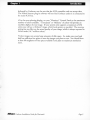
Let's take a look at Coolscan's front panel, as shown in Figure 2.1. The uncomplicated design of the front panel is indicative of how simple Coolscan is to use. The
front panel of the LS-l 0 and LS-l OE is identical. The front panel consists of the film
slot, focus wheel, and power/busy/error indicator light.
Focus Wheel
Nlkon
.CDDl..SCAI'1.
PowerlBusylE ITor
Indicator LED
Film Slot
Insert Slide Here
"-
~
~
1
.1
?"-~
Figure 2.1 Coolscan's front panel.
Film Slot
The film slot is the opening into which you insert your slides or film strips (using
the supplied film strip holder) for scanning. Slides and film strips are likewise ejected
from the film slot.
A high degree of care must be exercised with the film slot. Since this opening
allows the film ro enter the scanner, it thus provides access to its delicate instrumentation.
Never insert any object into the film slot, other than mounted film or the provided
film strip holder. Flammable materials, metals, water, etc., will cause fire, electrical shock and damage to the unit.
Focus Wheel
The focus wheel is used to fine-focus during scanning operation. This control is
provided because of the wide variety of film and film mounts available, which affect the
focusing function of the scanner.
Nlkon
Coolscan Imtallation Guide for Macintosh
Page 7
Setting Up Cooiscan
Chapter 2
The focus wheel must be in its center position during power up. T he center position is indicated by the black line across the focus wheel being centered in the visible
portion of the focus wheel .
Power/Busy/Error Indicator Light
The green power/busy/error indicator light has several functions. First, during
power-up it blinks at one-second intervals until Coolscan's power-on self-test and autoca1ibration has completed. Second, after the self-test and autocalibration is complete, the
light stays on constantly, indicating that Coolscan is ready to scan. T hird, during scanning, the light will blink at two-second intervals, indicating that the scanning operation
is in progress. Lastly, the ligh t will blink rapidly if an error is detected, in which case the
scanner will either recover on its own, or may have to be powered off and back on to
effect a reset.
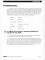
To summarize:
Power-up: LED blinks at 1 second intervals
Coolscan is ready: LED is on constantly
Coolscan is scanning: LED blinks at 2 second intervals
Error condition: LED blinks rapidly
If you are installing an LS-IO model, please proceed to the section "The Rear
Panel- LS-IO."
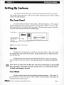
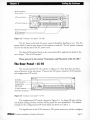
The Rear Panel - LS-l OE
T he rear panel of the LS-l OE is shown in Figure 2.2. Note that there are five
items of interest on the rear panel. T hese are the AC power switch, AC power connector,
the two SCSI connectors, the SCSI termination power switch, and the SCSI ID switch.
Page 8
Nikon
Coolscan Installation Guide for Macintosh
Chapter 2
Setting Up Cooiscan
SCSI Termination
Power Switch -----------------~
AC Power Switch --+MrrT.=;::w~rr;;;;;:;;;;~;;;;~;;;;:;;;;:l}~2~1
<iJ.
~~
~:::::::::::::::::::::::::V
SCSI
AC Power Connector
SCSI Locking Clips- - - - - - - . J
SCSI Connectors - - - - - - - - - - - . J
SCSI LD Switch - - - - - - - - - - - - - - - - - /
Figure 2.2 Coolscan's rear panel - LS-lOE.
The AC power switch and AC power connector should be familiar to yo u. The AC
power switch is used to turn power to the scanner on and off. The AC power connector
receives the female end of the AC power cord.
The three SCSI-related items on the rear panel will be explained in detail in the
next chapter, "The SCSI Interface."
Please proceed to the section "Orientation and Placement of the LS-I0E."
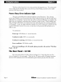
The Rear Panel - LS-l 0
The rear panel of the LS-l 0 is shown in Figure 2.3. Note that there are three
items of interest on the rear panel. These are the DC power connector, SCSI connector,
and configuration DIP switch.
11==
SCSI Pin I
SCSI Conn ector
Configurat ion
DIP Switch
IO-Pin Con nector
DC Power Connector
=1
I
\
I
'
"
II ~.I~
·· .... ·...... ·\~I ~tffA>j~ I
.....
. ........
........................
I
I
L..LJ
Figure2.3 Coolscan's rear panel- LS-IO.
The configuration DIP switch is shown in Figure 2.3. In almost all cases, the factory default settings of these switches will be proper for your installation. The default
settings for the configuration DIP switch block are shown in Table 2.l.
The significance of the SCSI connector, DC power connector, and the configura-
Nikon
Coolscan Installation Guide for Macintosh
Page 9
Setting Up Cooiscan
Chapter 2
tion DIP switch is discussed in greater detail in Chapter 3, "The SCSI Interface." For
now, note that the scanner is set at the factory to SCSI 10 #5 and to termination OFF.
Disregard the IO-pin connector at the bottom-left side of Figure 2.3. This connector is
not used when installing the LS-l 0 in a Macintosh.
DIP Switch
1 (Down)
2 (Up)
3 (Down)
4 (Up)
Default
Usage
On
SCSI 10 bit 0 = 1
Off
SCSI 10 bit 1 = 0
On
Off
SCSI 10 bit 2 = 1
SCSI Termination = Off
Table 2.1 Factory default settings for configuration DIP switch block.
Please proceed to the section "Transporting Coolscan."
Orientation and Placement of the LS-l OE
Proper Orientation
The following guidelines and precautions should be adhered to when deciding on
orientation of your LS-l OE.
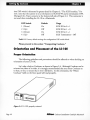
Let's take a look at Coolscan, as shown in Figure 2.4. Although Coolscan can be
oriented on either of its sides, it is strongly recommended that you orient Coolscan on
its base, or feet, to ensure that it won't fall down. In this orientation, the "Nikon
Coolscan" label on the front panel will read properly.
Figure 2.4 LS-IOE, properly oriented.
Page 10
Nlkon
Coolscan Installation Guide for Macintosh
Chapter 2
Setting Up Cooiscan
Proper Placement
The following guidelines and precautions should be adhered to when deciding on
placement of your LS-lOE:
1. Place Coolscan near the computer so that the maximum suggested SCSI cable
length (6 feet) is not exceeded.
2. Place the scanner so that it is easy to reach.
3. Coolscan should be placed on a flat, stable surface, free from vibration.
4. Keep the scanner away from damaging liquids by locating it away from sinks,
coffee pots, etc.
5. Protect Coolscan from dampness, high humidity, and excessive dust or smoke.
Dust and smoke, in particular, can cause undesirable effects on the scanner's optical
systems, requiring extensive cleaning and maintenance to correct.
6. Avoid locations where a sudden change in temperature might cause condensation
inside the scanner.
7. Protect the front of the scanner from direct sunlight or bright lights.
8. Avoid places with extremely hot or cold temperatures (below 10 degrees Celsius
or above 35 degrees Celsius).
9. Avoid placing Coolscan near heat sources.
10. Avoid any physical shocks to the scanner. Do not store the unit where it will be
subject to vibration.
11. Avoid placing Coolscan too close to other peripherals, and make sure there is
sufficient air circulation on all sides of the scanner.
Transporting Coolscan
The following guidelines and precautions should be adhered to when transporting
your Coolscan:
1. Always use the original packaging materials.
2. If the original packaging materials are unavailable, use appropriate packaging
Nikon
Coolscan Installation Guide for Macintosh
Page 11
Setting Up Cooiscan
Chapter 2
materials for precision instruments. If you are shipping your Coolscan back to
Nikon, Nikon will not be responsible for damages incurred due to improper packagmg.
3. The focus wheel must be turned all the way downward to the end of its travel
before shipping.
4. Pay special attention to the air or courier service
to
ensure that they can properly
handle this precision instrument.
If you are installing an LS-IO, please proceed to the section "Installation
Precautions."
Connecting AC Power to the LS-l OE
The scanner's AC power cord is a standard three-wire grounding plug. This plug
will fit only a grounded AC outlet. Intended to be a safery feature, the grounding connector should not be defeated. Additionally, an electronic surge protector is highly recommended.
Safety Precautions When Connecting '
AC Power to the LS-l0E
to
The following precaurions should be complied with when connecting AC power
the scanner:
1. Always use a proper power source of 115V AC or 230V AC, 50 to 60 Hz.
2. Do not hold the cord itself when plugging or unplugging the AC power. Hold
the plastic portion of the connector itself rather than pulling on the cord.
3. If you lose the supplied power cord, use an appropriate replacement that is subject
to the voltage of the power source, using the following guidelines:
• If a 230V AC power source is used, make sure that the plug is rated at 250V AC,
15A (NEMA 6P-16).
• If a 115V AC power source is used, the plug must be rated at l20V AC, lOA.
• The gauge of the cord must be at least 18 gauge (remember, the smaller the gauge,
the thicker the wire. For example, 18 gauge is thicker than 20 gauge).
Page 12
Nikon
Coolscan Installation Guide for Macintosh
Chapter 2
Setting Up Coolscan
• The cord must be approved by the safety regulations of the countty where it is
used.
• A p~operly grounded three-conducror AC power source is required in order to
reduce electrical noise and the possibility of electrical shock.
Ae Power Safety Precautions - LS-l OE
The following safety guidelines should be adhered to concerning AC power and
Coolscan:
1. Once the AC power source is turned off, either through the Cools can power
switch or other AC power switch, wait at least 5 seconds before powering on again
to ensure the proper power-up sequence.
2. Don't unplug the AC power cord from the AC source or from the Coolscan AC
power connector while the Coolscan AC power switch is on. To be completely safe,
don't unplug any other peripheral while Coolscan is powered on.
3. Do not move Coolscan while its power is on.
4. Never disassemble the scanner. It is very dangerous to touch the devices inside
the unit due to high voltages, and there are no user serviceable parts inside. Such
action may be a violation of your Nikon Limited Warranty, and would render the
warranty null and void.
Installation Precautions
The following guidelines should be observed when installing Coolscan:
1. Make certain that power to all instruments directly connected to Cools can (via
SCSI) is turned off before beginning the installation. This includes the AC power
switch on Coolscan (LS-10E only) .
If you are installing an LS-1 0, there is no AC power switch since it relies on the
Macintosh's power. Therefore, make sure that the Macintosh's power is off.
2. Turn off the power to all peripherals connected to the computer (display, printer,
etc.).
3. If your Macintosh has a key-lock facility, turn the key to the unlock position.
4 . Unplug the AC power cable to the Macintosh.
Nikon
Coolscan Installation Guide for Macintosh
Page 13
Setting Up Cooiscan
Chapter 2
5. When mounting Cools can into the Macintosh (LS-IO only), be especially mindful to eliminate electrostatic discharge, as it can damage the scanner.
Electrostatic discharge will damage the scanner if you touch its SCSI connector
pins. Do not touch the pins.
General Safety Precautions
Always power off Cooiscan and/or remove the power cord from the AC
source when anyone of the following occurs:
1. The AC power cord (LS-lOE only) or 4-pin DC power plug (LS-IO only)
becomes damaged.
2. Any liquids are spilled into the scanner.
3. The scanner is exposed to excessive moisture.
4. The housing of the scanner is opened or has become damaged (LS-IOE only).
5. You suspect the scanner is not functioning properly.
6. Something unusual occurs, such as abnormal noise, odor, or smoke. In this case,
bring your Coolscan to the dealer where it was purchased or to an authorized Nikon
repair facility.
Operational Precautions
Never power on the scanner while the film strip holder is in the scanner slot.
Doing so will interfere with the scanner's normal startup calibration procedure,
resulting in incorrect color capture while scanning, and possible SCSI errors.
2. Do not attempt to insert slide mounts into Coolscan that are over 3mm thick.
Remount the film into an appropriate holder.
3. Do not attempt to insert slide mounts into Coolscan that are not flat. Remount
the film into an appropriate holder.
4. Do not force a slide or the film strip holder into the Cools can film slot. A
smooth gliding action should be used during both insertion and removal.
5. Do not attempt to remove or reposition the slide or film strip holder in the
Cools can film slot during the scanning process.
Page 14
Nikon
Coolscan Installation Guide for Macintosh
Chapter 3
The SCSI Interface
The SCSI Interface
The computer interface used exclusively with Coolscan is called a Small
Computer System Interface (SCSI - pronounced 'scuzzy'). This interface has been
adopted as the standard in the Macintosh computing environment, and is utilized by
many computer peripherals including disk drives, scanners, printers and CD-ROM
drives.
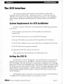
System Requirements for SCSI Installation
In order to connect a SCSI device to the Macintosh, the following requirements
must be met:
1. The computer system must have a SCSI controller (most Macintosh
computers do).
2. The SCSI device must be set to an unused SCSI ID number.
3. A proper SCSI cable must connect the SCSI controller to the SCSI device.
4. The SCSI bus cabling must be correct if more than one peripheral shares the bus.
5. The SCSI bus must be properly terminated.
6. Appropriate SCSI driver software must be used.
These requirements will be addressed in the following sections.
Setting the SCSI ID
The SCSI bus is a sort of 'data highway,' with the SCSI devices connected to the
SCSI bus representing 'stops' on this highway. Each device requires its own distinct
SCSI ID number so that the Macintosh can easily locate it through the SCSI controller.
Because the SCSI bus can accommodate up to seven devices, internal or external, a SCSI
ID number can have a value between 0 and 6. There are no implicit regulations regarding the allocation of these numbers. Typically, however, the Macintosh's SCSI controller would be assigned SCSI ID number 7, while the SCSI devices would be numbered 0 through 6.
The SCSI ID number is commonly set by a switch on the rear of the SCSI device.
The default SCSIID number of Coolscan, set at the factory, is ID #5.
Nikon
Coolscan Installation Guide for Macintosh
Page 15
The SCSI Interface
Chapter 3
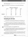
Determining Which SCSI ID Number to Use
If Coolscan is the only external SCSI device that will sit on the SCSI bus, there is
no need to change the SCSI ID number from the factory setting. This is assuming that
your internal hard disk is set to SCSI ID #0.
If Coolscan must share the SCSI bus with one or more other SCSI devices, it is
necessary to ensure that no two devices are using the same SCSI ID number. Create a
list of all SCSI devices (See Table 3.1) on the SCSI bus of the Macintosh you will be
installing Coolscan on, noting the device type and the SCSI ID number of each device.
You can discover the SCSI ID of some disk drives by selecting the disk drive in the
Macintosh Finder and selecting GET INFO from the FILE menu. To determine the SCSI
ID number of other devices, look at the rear of each for some indication. If there is no
indication as to the SCSI ID number, then consult with the device's user's manual or
contact the peripheral manufacturer to ascertain this information.
Never change the SCSI ID number of a SCSI device while its power or the
computer's power is on.
SCSIID
Device Type
o
Internal Disk Drive
2
3
4
5
6
7
Coolscan Scanner (default>
Macintosh Computer
Table 3.1 Typical SCSI ID number chart.
If another SCSI device shares the same SCSI ID #5 of Coolscan, change the SCSI
ID number of Cools can to an unused number, as indicated in the following sections.
Note any changes in Table 3.1.
If you are installing an IS-IO, please proceed to the section "Setting the SCSI
ID -IS-IO."
Page 16
Nikon
Coolscan Installation Guide for Macintosh
Chapter 3
The SCSI Interface
Setting the SCSI ID - LS-1 OE
If necessary, the SCSI ID number of the LS-1 OE can be set via a switch on the
back of the scanner, as shown in Figure 3.1. Simply push the button above the SCSI ID
number indicator to decrement the SCSI ID number. Conversely, push the lower button
to increment the SCSI ID number.
Top Bu tton
(push to decrement)
~
•
SCSI lD Switch
SCSI lD # Indica tor
ffi]
CQ
Bottom Button
(push to Increment)
SCSI lD
Figure 3.1 SCSI ID switch on the rear of Coolscan - LS-l DE.
Please proceed to the section "Terminating the SCSI Chain."
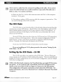
Setting the SCSI ID - LS-1 0
If necessary, the SCSI ID number of the LS-lO can be set via the block of configuration DIP switches on the back of the scanner, as shown in Figure 3.2. For most
installations, these configuration DIP switches will not require changing.
Configuration DIP
Switch - - - - - - - - 0
Typicall y reserved
~
for computer ----..~
~
1
~
~
2
~
~
3
~OFF
~ON
4 5 6
OFF~
~
Factory defau lt ON ~
~
for Coolscan _ _ _ _ _ _-==;Il
~
~
Figure 3.2 Configuration DIP switch block on the rear of Cools can - LS- IO.
To change the positions of the configuration DIP swi tches to the desired SCSI ID
number, use Table 3.2 for proper switch positions. Use a small pointed instrument to
toggle the switches, such as a very small screwdriver. It is not recommended to use a
Nikon
Coolscan Installation Guide for Macintosh
Page 17
The SCSI Interface
Chapter 3
pencil or pen, since these will discolor the switch and make it hard to differentiate the
ON versus OFF position.
Never use SCSI ID #7 for a SCSI device, as it is reserved for the Macintosh.
DIP Switch Configuration
0
DIP #1
Off
1
On
DIP #2
Off
Off
2
On
On
Off
3
Off
On
4
Off
Off
On
2
On
Off
On
6
Off
On
On
SCSI ID
Default ID
DIP #3
Off
Off
Off
Table 3.2 Configuration DIP switch values for corresponding SCSI ID number.
SCSI ID #5 indicates factory default setting.
Terminating the SCSI Chain
The SCSI chain is the electrical bus connecting rwo or more SCSI devices. It is
critical that this bus be correctly terminated for the SCSI devices to operate properly.
Termination is an electronics term that applies to the impedance found at both
ends of the bus. The electrical signals on the SCSI bus are changing rapidly berween
their digital 'on' and 'off states. To minimize electrical 'noise,' a terminator is placed on
each end of the SCSI bus. The effects of this termination may be unseen to you, but are
critical nonetheless.
Incoccect SCSI termination can cause unpredictable eccors.
Typically, the Macintosh internal SCSI connector has a hard disk drive connected
to it and is terminated. Quadra models have a special internal SCSI cable which has termination installed at the end of the cable. All internally mounted SCSI devices in
Quadra 900/950 systems should not be terminated.
If one other SCSI device shares the SCSI bus, it also must be terminated. If additional SCSI devices sit on the bus in berween the rwo end SCSI devices, these devices
cannot be terminated. The SCSI chain wilL only operate properly if termination is in place
at the beginning and end ofthe SCSI bus.
Page 18
Nikon
Coolscan Installation Guide for Macintosh
Chapter 3
The SCSI Interface
SCSI termination remains more of an art than a science. You may find that your
computer will not recognize all of the SCSI devices installed when you restart your system after connecting Coolscan. You may need to deal with a number of special case situations. For example, the Macintosh Quadra requires specific installation procedures
not applicable to other Macintosh systems. The Macintosh HEx is another special case.
The HEx should only be terminated using the black terminator that is supplied with the
system. Using the gray terminator, which is supplied with Coolscan, may cause damage
to the computer. If you don't have the special black terminator, contact your authorized Apple dealer to obtain one.
If you are installing an LS-I0, please proceed to the section "Terminating the
LS-I0."
Terminating the LS-l OE
The LS-IOE is configured with two 50-pin SCSI connectors on the rear of the
unit, as shown in Figure 3.3. Install the standard 50-pin SCSI terminator (remember,
you need the special black terminator for a HEx) onto the bottom connector if termination is desired. If you would like Coolscan to reside in the center of the SCSI chain,
then by necessity, the bottom connector will be used for a SCSI to SCSI jumper cable.
SCSI
connectorsJ~~~f~5;;;::s~~;:
Figure 3.3
SCSI Terminator on the rear of Cooiscan -
LS-l DE.
Termination Power
Unlike other Macintosh computers, the PowerBook does not supply SCSI termination power. To use the LS-IOE with a PowerBook, the SCSI Termination Power
Switch, labeled "TERM PWR" on the rear of the unit (see Figure 2.2) must set to the
ON position. This configuration will require termination at both ends of the SCSI
chain. For further information, refer to the Macintosh User's Guide for Macintosh
PowerBook Computers.
Nikon
CooLscan Installation Guide for Macintosh
Page 19
The SCSI Interface
Chapter 3
To use the LS-I OE with all other Macintosh computers, the TERM PWR switch
must be set to the OFF position.
Please proceed to the section "SCSI Cables."
Terminating the LS-l 0
Setting termination on the LS-l 0 is simple. Termination is controlled by the
position of the #4 switch of the configuration DIP switch block. If you recall, setting
the SCSI ID number required use of only the #1, #2, and #3 switches.
~
.
Configuration
DIP Switch - -
-
SCSI termination
Off -----------,~~
SCSI termination on
.
-----_
\
~
-----------~~
Figure 3.4 SCSI termination using configuration DIP switch #4 on the rear of the LS-l O.
If switch #4 is in the ON position, Coolscan is internally terminated. If switch #4
is in the OFF position (the factory default setting), Coolscan is not internally terminated. These two settings are shown in Figure 3.4.
SCSI Cables
There are three basic rypes of SCSI cables that can be used with Coolscan. These
are aliSO conductor cables, i.e. they have 50 contacts, or 'pins.' These three cables are
described below.
If you are installing an LS-I0, please proceed to the section "SCSI Cables
Used With the LS-I0."
SCSI Cables Used With the LS-l OE
Three different rypes of SCSI connectors exist on Macintosh computers. The first
is a 25-pin DB-25 rype connector, the second is a Centronics 50-pin rype connector, and
the third is the HDI-30 connector, found on Macintosh Powerbooks. To use Coolscan
(or any other SCSI device) with a Powerbook, you should purchase the Apple HDI-30
SCSI Cable, which plugs into the Powerbook's SCSI connector and provides a
Page 20
Nikon
Coolscan Installation Guide for Macintosh
Chapter 3
The SCSI Interface
Centronics 50-pin female connector, sim ilar to what is found on the rear of Coolscan.
The SCSI cab le provided with your LS-IOE has a DB-25 connector on one end, and a
Centronics 50-pin connector on the opposite end, as shown in Figure 3.5a. This cable is
used for the default configuration of Coolscan, which is making the scanner the first device on
the SCSI bus.
50-pin Centronics -------------~"
25-pin D825 - - - - - "
(a) 25-pin DB25 to
50-pin Centronics
SCS I Cable
50-pin Centronics
~.
;:=:;
\.. ~;;;::::::::;;~~
~
~]
'-----'
,' - - - - - - /J
~~)
s::::==:::::;
(b) 50-pin Centronics
"""
to 50-pin Centronics
SCS I Cable - - - - - - - - - •
~~~;;;;;;;:lr
"
"
'T~
~
]
,' - - - - - - /J
Figure 3.5 SCSI external cables. a) The 25-pin DB-25 ro Centro nics 50-pin cable.
(b) T he Centronics 50-pin to Centronics 50-pin cable.
If you plan on placing Coolscan in the middle of the SCSI chain, you will need a
Centronics 50-pin to Centronics 50-pi n SCSI cable, as shown in Figure 3.5b. This
cable is not supplied with Coolscan.
SCSI cables should never be connected or disconnected while the computer's or
SCSI device's power is on. Such action can damage the SCSI controller chip on
your Macintosh, requiring a motherboard replacement.
Please proceed to the section "The Macintosh's External SCSI Connector."
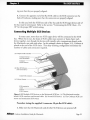
SCSI Cables Used With the LS-l 0
The SCSI cable provided with the LS-IO enables yo u to connect the scanner to
the Macintosh's SCSI chain as either the only device on the SCSI bus, or as an additional device. This is a chainable SCSI flat cable with two identical crimped connectors on
each end and one connector crimped in the center, as seen in Figure 3.6a.
If Coolscan is to be the only internal SCSI device: Connect one end of this
cable to the existing SCSI bus in the Macintosh (connecting the SCSI cable to the
Macintosh's SCSI bus will be explained in the next section), then connect the opposite
end to the SCSI connector on the rear of Coolscan (refer to Figure 2.3 to locate the
SCSI connector). The center connector is not used. Make sure that DIP switch # 4 is
in the termination ON position, as indicated in Figure 3.4.
Nikon
Coolscan Installation Guide for Macintosh
Page 21
The SCSI Interface
Chapter 3
If Coolscan is to be connected in the middle of the SCSI chain: Connect one
end of this cable to the existing SCSI bus (connecting the SCSI cable to the Macintosh's
SCSI bus will be explained in the next section), connect the center connector to the
SCSI connector on the rear of Coolscan, and connect the last connector to yo ur internal
disk drive.
(a) Chai nable SCSI Flat r~ I,I ,, -----="""'::~"~
(provided)
SCSI 50-Pin
/
/
Connectors _ _ _L_ _ _ _ _L_ _ _ __
Connector
Protection Key - - - - - - - - - - - - - "
(b) Non-chai nable SCSI - - - - - -__
Flat Cable (not provided)
SCSI 50-Pin Connectors
Connector Protection Key _ _ _ __ _ _ _ _---===-_..J
Figure 3.6 SCSI Rat cables. (a) Chainable SCSI Rat cable provided with Cooiscan.
(b) Non-chainable SCSI Rat cable.
The cable seen in Figure 3.6b is a non-chainable SCSI flat cable. If yo u already
have one of these, it can be used instead of the supplied cable if you are installing
Coolscan as the last device in the SCSI chain.
Make sure that DIP switch #4 is in the termination OFF position, as indicated in
Figure 3.4.
SCSI cables should never be connected or disconnected while the computer's or
SCSI device's power is on. Such action can damage the SCSI controller chip on
your Macintosh, requiring a motherboard replacement.
Please proceed to the section "The Macintosh's Internal SCSI Connector."
Page 22
Nikon
Coolscan Installation Guide for Macintosh
Chapter 3
The SCSI Interface
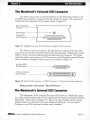
The Macintosh's External SCSI Connector
The SCSI connector for external SCSI devices on the Macintosh, which is a 25pin DB25-type connector, is found on the Macintosh's rear panel. This connector is
indicated by the Macintosh's SCSI symbol, shown in Figure 3.7.
Back of Macintosh
Computer - - - - - - - - 1 . - .
SCSI Symbol - - - - - + - - - - - 25-pin OB25
SCSI Connector
----+---+-@
0000000000000
000000000000
@
Figure 3.7 Simplified rear view of the Macintosh computer's SCSI connector.
The 50-pin Centronics connector, the type used on Coolscan, is the most common connector used for external SCSI devices on the Macintosh. This ~s why a 25-pin
DB25 to 50-pin Centronics cable has been provided with your Coolscan. The 25-pin
end of the cable is connected to the SCSI connector on the Macintosh, and the 50-pin
end to Coolscan. Examples of these connectors are shown in Figure 3.8.
(a) 25-pin OB25
SCSI Connector - - - - - - - - - -...
(b) 50-pin Centronics
SCSI Connector
----.
~
~
V* ~:::::::::::::::::::::::::V-av
Figure 3.8 Typical SCSI connectors. (a) DB25 connector. (b) 50-pin Centronics connector.
Please proceed to the section "The SCSI Chain."
The Macintosh's Internal SCSI Connector
The Macintosh's SCSI connector for internal SCSI devices, a 50-pin flat connector, resides inside the Macintosh on the motherboard (the main circuit board inside the
Macintosh). This is shown in Figure 3.9. Please note that Coolscan will not operate
properly unless it is connected to the main Macintosh SCSI port. Do not connect
Coolscan to any SCSI accelerator card that may be installed.
Nikon
Coolscan Installation Guide for Macintosh
Page 23
The SCSI Interface
Chapter 3
Connecting to the Internal SCSI Connector
Again, the SCSI connector on the Macintosh's motherboard is a 50-pin flat connector, as shown in Figure 3.9. Note the position of pin 1 and the safety key. The safety
key provides a level of protection against inserting the cable improperly.
Typical SCSI Connector on
Macintosh Motherboard
Motherboard _ _ _ _ _ _ _ _-'S~__
SCSI Connector -----------"':~I
SCSI Flat Cable - - -- - -- - - - -.. v.!1;;;.rr"-:
Pin I Indicator _ _ _ _ _ _ __ _ _ _ _ _....:>..
Figure 3.9 The 50-pin flat SCSI connector inside the Macintosh on the morherboard.
If for some reason you choose not to use the internal SCSI cable provided with
your Coolscan (you won't be using it for installing Coolscan in the Macintosh Quadra
Series), note that there is a wide variety of 50-pin flat SCSI connectors and SCSI cables.
They are all functionally the same, yet vary in some important ways:
1. Some cables might not have a safety key. In this case, take extra precautions to
ensure that the mating cables' connectors are properly aligned prior to insertion.
2. Some connectors may not have Pin 1 clearly marked on the connector.
3. Some cables may have Pin 1 on the cable indicated in red.
4. Some connectors will not have mechanical side levers to assist in plugging and
unplugging the cable.
Care must be exercised when inserting and removing rhese 50-pin connectors,
shown in Figure 3.9, as they are rather fragile. Observe the following guidelines when
handling these connectors:
1. Never force the connector in or out. If you bend or break any of the pins,
replacement of your motherboard will be required.
2. Make sure that the mating connectors are aligned properly before inserting. Take
extra care in rhis very critical step.
3. Push rhe cable connector gently into the mating connector. Once in place, push
down firmly.
Page 24
Nikon
Coolscan Installation Guide for Macintosh
Chapter 3
The SCSI Interface
Never remove a cable from the connector by pulling on the cable. If you cannot
remove the cable by hand, use a small screwdriver to pry each of the sides out, a
little at a time. Use caution at all times.
4. Make sure that Pin 1 of the cable connector mates with Pin 1 of the computer
connector. Never guess.
5. Never plug or unplug a SCSI connector while the computer is powered on. This
can result in damage to the SCSI controller.
The SCSI Chain
The SCSI chai n, as yo u learned earlier, is the electronic data and control bus that
connects two or more SCSI devices. The SCSI bus is the 'data highway' and the SCSI
devices linked together forming the SCSI chain represent 'stops' on the highway. As
mentioned at the start of this chapter, the SCSI chain can accommodate up to seven
devices on the SCSI bus.
On any SCSI bus, there must be at least one SCSI host and one SCSI target device.
Coolscan is always a SCSI target device. This is the standard configuration for SCSIbased scanners. In fact, most devices connected to computers will be SCSI target
devices. Typically, the Macintosh will always be the SCSI host.
In any case, the SCSI 10 number of each device must be unique.
If you are installing an LS-I0, please proceed to the section "Setting Up the
SCSI Chain - LS-I0."
Setting Up the SCSI Chain - LS-l OE
The LS-IOE can reside at any position in the SCSI chain. The two 50-pin connectors on the rear of Coolscan are both used for this purpose. There are essentially two
possible SCSI chain configurations, the two SCSI devices configuration, and the muLtipLe
SCSI devices configuration.
Unlike other Macintosh computers, the PowerBook does not supply SCSI termination power. To use Coolscan with a PowerBook, the SCSI Termination Power
Switch on the rear of the LS-I0E (see Figure 2.2) must set to the ON position.
This configuration will require termination at both ends of the SCSI chain. For
further information, refer to the Macintosh User's Guide for Macintosh PowerBook
Computers.
Nikon
Coolscan Installation Guide for Macintosh
Page 25
The SCSI Interface
Chapter 3
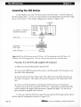
Connecting Two SCSI Devices
In the simplest case, only two devices share the SCSI chain - the SCSI host and
the SCSI target device. In our case, the SCSI host is the Macintosh and the SCSI target
device is the scanner. This simple configuration is shown in Figure 3.10.
[ll]
Card Slots
DB-25 DB-IS
SCSI Video
(a) Computer - SCSI Host(internally terminated)
Port
Port
.!}
.!}
SCSI Cable - - - - - - - - - -
(b) Scanner SCSI Target
SCSI Terminator
-------~)
(
Figure 3.10 Two SCSI devices on rhe SCSI bus. (a) The Macintosh is me SCSI host. (b)
Coolscan is rhe SCSI rarger device. The rear view of your sysrem may nor be me same.
Procedure (Use the SCSI cable supplied with Coolscan):
1. Make sure that the Macintosh is powered off.
2. Connect the DB25-pin side of the cable to the Macintosh's SCSI connector (on
the back of the Macintosh).
3. Connect the Centronics 50-pin side of the cable to the top SCSI connector on
the back of Coolscan. This cable will connect Coolscan to the Macintosh's SCSI
bus.
4. Connect a SCSI terminator to the bottom SCSI connector on the back of
Coolscan, since this is the end of the SCSI chain. Termination on Macintosh HEx
systems requires the proper black terminator, supplied by Apple. Do not use the
gray terminator supplied with Coolscan.
In this case, both the SCSI host side of the bus and the SCSI target device side of
the bus must be terminated, as shown in Figure 3.10.
Page 26
Nikon
Coolscan Installation Guide for Macintosh
Chapter 3
The SCSI Interface
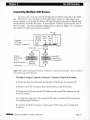
Connecting Multiple SCSI Devices
In many cases, more than one SCSI target device will be connected to the SCSI
bus. When this is true, the chain of SCSI cables must connect or 'daisy chain' each
device together, even though the devices will typically only communicate directly with
the Macintosh, not with each other. In this example, Cools can is placed at the end of
the SCSI chain. This daisy chaining configuration, as shown in Figure 3.11, minimizes
the number of cables and connectors required.
Card Slots
ComputerSCSI Host
(internally terminated)
SCSI Cable-
c::=s
=
Scanner~
SCSI Target ~:
:
DeVIce
SCSI Terminator
--je (
==
-
Other SCSI
- Target Device
- (no termination)
SCSI Cable - - - - - - - - Ih,,=d)
Figure 3.11 D aisy chaining SCSI devices. Coolscan is at the end of the chain. The rear view of
your system may not be the same.
Procedure (using a Centronics 50-pin to Centronics 50-pin SCSI cable):
1. Make sure that the Macintosh and all other SCSI devices are powered off.
2. Remove the SCSI terminator from the last device in the SCSI chain.
3. Insert one end of the unused SCSI cables into the top SCSI connector on the
back of Coolscan.
4. Connect the other end of the unused SCSI cable to the free SCSI connector of
the neighboring SCSI device.
5. Connect the SCSI terminator to the bottom SCSI connector on the back of
Coolscan.
Nikon
Coolscan Installation Guide for Macintosh
Page 27
The SCSI Interface
Chapter 3
It is equally possible to configure the SCSI chain with Coolscan in the center of
the chain. In this case, the SCSI terminator would reside on the optional device, as
opposed to Coolscan.
Please proceed to the section "Important Information About the SCSI
Interface."
Setting Up the SCSI Chain - LS-l 0
The LS-10 can reside at any point in the SCSI chain. There are essentially two
possible SCSI chain configurations, the two SCSI devices configuration, and the muLtipLe
SCSI devices configuration.
Connecting Two SCSI Devices
In the simplest case, only two devices share the SCSI chain - the SCSI host and
the SCSI target device. In our case, the SCSI host is the Macintosh and the SCSI target
device is the scanner. This simple configuration is shown in Figure 3.12.
(a) Computer SCSI Controller ----------.,.
Computer Internal
SCSI Termination
Computer
SCSI Connector --------~=---+'LU::::::::;:::::;;::
Unused center ------------------------__________--'
SCSI Connector
(b) SCSI Cable ---------------------------:::::,.......=:;..~~
(c) .Coolscan SCSI Connector
SCSI termination
S WItCnl----------------------------~
Figure 3.12 The Macintosh internal SCSI Bus. (a) The Macintosh motherboard's SCSI connector and internal SCSI cable. (b) SCSI cable. (c) The Coolscan SCSI connector and termination
DIP switch.
Procedure (Use the SCSI cable supplied with Coolscan):
1. Make sure that the Macintosh is powered off.
2. Connect one end of the flat SCSI cable to the Macintosh's SCSI connector, makPage 28
Nikon
Coolscan Installation Guide for Macintosh
Chapter 3
The SCSI Interface
ing sure that they are properly aligned.
3. Connect the opposite end of the flat SCSI cable to the SCSI connector on the
back of Coolscan, making sure that the connectors are properly aligned.
In this case, both the SCSI host side of the bus and the SCSI target device side of
the bus must be terminated. Refer to the section "Terminating the SCSI Chain - LS10" for the proper DIP switch setting.
Connecting Multiple SCSI Devices
In many cases, more than one SCSI target device will be connected to the SCSI
bus. When this is true, the chain of SCSI cables must connect or 'daisy chain' each
device together, even though the devices will typically only communicate directly with
the Macintosh, not with each other. In this example, shown in Figure 3.13, Coolscan is
placed at the end of the SCSI chain. This daisy chaining configuration minimizes the
number of cables and connectors required.
<a) Computer SCSI Cor'rrolle r - - - - - ,
Computer Internal
SCS I Termination
- - --;;;-"0:;:-
Computer ----....".,=:::;;;::-l..,[l.l.-:::;;:;;;;~
SCSI Connector
(b) Other SCS I Device - - - -(such as disk drive)
Center SCSI connector - - - - - - ,
(c) Coolscan Scanner - - - - : ; : : +
SCSI termination
switch - - - - - - - " " '==--- '
Coo l ~a n--------------~
SCSI Connector
Figure 3.13 Multiple SCSI devices on the Macintosh SCSI bus. (a) The Macintosh motherboard's SCSI connector and internal cable. (b) Second SCSI device. (c) The Coolscan SCSI connector and termination DIP switch.
Procedure (using the supplied 3-connector 50-pin Sat SCSI cable):
1. Make sure that the Macintosh and all other SCSI devices are powered off.
Nikon
Coolscan Installation Guide for Macintosh
Page 29
The SCSI Interface
Chapter 3
2. Remove SCSI termination from the last device in the SCSI chain.
3. Remove the SCSI cable currently in use from the Macintosh's SCSI connector on
the motherboard, and the other end from the SCSI device.
4. Connect one end of the supplied 3-connector flat SCSI cable to the SCSI connector on the Macintosh's motherboard.
5. Connect the middle connector of the supplied SCSI cable to the SCSI connector
of the neighboring, now middle, SCSI device.
6. Insert the unused end of the SCSI cable into the SCSI connector on the back of
Coolscan.
7. Since Coolscan is now at the end of the SCSI chain it must terminated. Refer to
the section "Terminating the LS-10" for the proper DIP switch setting. Because the
Macintosh is at the other end of the chain, it also must be terminated.
It is equally possible to configure the SCSI chain with Coolscan in the center of
the chain. In this case, the SCSI terminator would be installed on the last device in the
SCSI chain, as opposed to Coolscan. Don't forget, Quadra systems should have no termination on any internal device when using the Apple internal SCSI cable. If the LS-1 0
is the last device in the SCSI chain, then DIP switch #4 should be set to the termination
ON position.
Important Information About the SCSI Interface
There are several advantages and limitations
should be aware of:
to
the SCSI interface which you
1. It is a standardized interface • The SCSI-1 ASPI 3.1 interface was standardized in 1986. This has made possible the use of any single SCSI-1 standard device with
any computer system that supports the SCSI-1 interface standard, such as the
Macintosh.
Advantages: • Because of the vast array of competing third-parry developers,
SCSI hardware is relatively inexpensive and plentiful. • SCSI-based software is well
defined and widely supported.
Limitations: • Although the SCSI-1 interface itself is standardized, the computerto-SCSI interface is not. Consequently, each SCSI controller may have its own computer interface. • Different SCSI devices cannot necessarily be controlled with the same
host code. Therefore, there are times when it is best to use provided SCSI controllers
for different SCSI devices instead of chaining the SCSI devices.
Page 30
Nikon
Coolscan Installation Guide for Macintosh
Chapter 3
The SCSI Interface
2. It is a multi-device interface.
As noted throughout this chapter, the SCSI interface can support up to seven
independent SCSI devices, one of which is your Macintosh.
Advantages: • Ability to daisy chain multiple devices off of one interface to the
computer. • Allows easy system expandability.
Limitations: • Not all SCSI devices can work together on the same SCSI bus. •
Some SCSI devices will not operate correctly if daisy chained in a particular order. This
may require that you experiment with the order of the devices in the daisy chain. •
Some SCSI devices are internally-terminated at the factory. This may require that you
or a qualified technician remove this termination if the device is to be placed in the middle of a SCSI chain. • When daisy chaining many SCSI devices together, the total
length of all the SCSI cables used in the chain should not exceed 18 feet. A chain of
more than 18 feet may result in lost data and 'lost' devices. • System performance can
suffer as devices are added to the SCSI bus. This is related to the length of the SCSI
chain. Data has a longer path to travel as more devices and cables are added to the SCSI
chain, resulting in electrical instability and signal reflections. This leads to miscommunicated bytes, which must be re-sent until they are received correctly, a lengthy procedure.
3. It is a fast parallel interface.
Advantages: • The complex SCSI 'handshaking' is managed in hardware, allowing high speed variable size block transfers. In other words, the SCSI interface allows
fast transfer of blocks of data.
Limitations: • The parallel bus limits the length of the SCSI chain, and therefore
the distance between SCSI devices.
4. SCSI devices can easily be connected, disconnected, and moved.
Advantages: • Allows portability of devices between different computers. •
Allows easy relocation of devices. • Allows easy system expandability.
Disadvantages: • Connecting and disconnecting SCSI devices that reside on the
same SCSI bus as the computer's bootable disk can cause loss of data and/or damage to
the SCSI devices if performed while the computer or any SCSI device is powered on.
Never connect or disconnect SCSI devices while the computer or any SCSI device
is powered on.
Nikon
Coolscan Installation Guide for Macintosh
Page31
The SCSI Interface
Page 32
Chapter 3
Nikon
Coolscan Installation Guide for Macintosh
Chapter 4
Basic Operation
Basic Operation
Introduction
By this time you have completed the hardware setup portion of your Coolscan
installation. Installation of the Nikon scanning software is covered in the companion
user manual Software Reference for Scanners.
Before proceeding to the software installation, this chapter will introduce you to
the basic mechanical operation of Coolscan, including attributes of various film types
and slide mounts, orientations supported by Coolscan, care and preparation of the film,
proper usage of the film strip holder, and focusing.
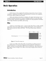
Film
Coolscan is a 35mm film scanner. Cameras using 35mm film are widely available
and handle a wide variety of film types, including color negative, color transparency
(slide) and monochrome (Black and White). The 35mm frame format is shown in
Figure 4.1 .
~ 36mm
35mm image area - - - - - - - - - - +
-------.j
I
24mm
~
Figure 4.1 35mm film image area.
In the case of slides, 35mm film will be returned from your film processor in
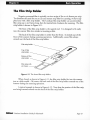
35mm slide mounts, or in the case of negatives, cut into strips of 5 or 6 frames in
length. Coolscan can accommodate either of these two film types. Film mounted in a
slide holder is shown in Figure 4.2a, while an uncut strip of negative film is shown in
Figure 4.2b.
Nikon
Coolscan Installation Guide for Macintosh
Page 33
Basic Operation
Chapter 4
1~'-----50mm------~'1
Slide M o u n t - -- - - '. r - - - - - ' l
(a) M ounted 35 mm fi lm --------------------1
+ - ,----=-=::.:.:..:.----1
Fi lm
--------------------------*-~
50mm
,------J
Unexposed porti on
of film --------------~~~~~~~~~~~~~~
(b) Unmounted 35mm film
---------+_
Image portion
of fi lm ---------------------"------------"----------"
Figure 4.2 35mm film mounring. (a) Film in a typical slide mounr. (b) Film in an
uncut strip.
There are two basic formats for 35mm film, one being positive (slide or transparency) and the other negative. When looking at positive film , the image appears as
you would expect the printed image to appear. When looking at negative film, the
image is color reversed, with light areas appearing dark and dark areas appearing light.
Typically, negative film is used for making prints, and positive film is used to make
slides. Positive film is sometimes referred to as 'reversal' film.
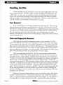
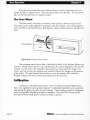
The front and back surfaces of the film are not the same. One side is known as
the emulsion. The opposite side is the base. To achieve optimal results when scanning,
the emulsion side should face the top of the scanner, as shown in Figure 4.3.
Page 34
Nikon
Coolscan Installation Guidefor Macintosh
Chapter 4
Basic Operation
.~. ~~~~~::~::~::::J{
lU
o
Emulsion side of fi lm - - - - ' - - - -
Base side of film _ _ _ _ _ _ _ _-----l\
Figure 4.3 Inserting the emulsion side of the film facing the top of Coolscan.
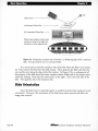
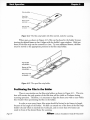
Slide Mounts
Both positive and negative film can be cut and mounted. These mounts can vary
in thickness and material. Typical 35mm slide mounts are composed of either cardboard or plastic, and mayor may not use glass. Coolscan can accept slide mounts that
are up to 50mm wide by 3mm thick.
The mounted film is assumed to be at the center of the slide mount, as shown in
Figure 4.4. The film will be centered in the scanner's focal field without user intervention.
Slide Mount ----------:;~==::------
____
..
Mounted 35mm film --------+-~ h(
Film
- - - - - - - + . . - - - - -<'
Emulsion side of film
-~====:;~:::::~~::::::::::~~
Figure 4.4 The film position concerning the center of the slide frame.
Nikon
Coolscan Installation Guide for Macintosh
Page 35
Basic Operation
Chapter 4
Handling the Film
Proper handling and care of the film is critical to ensure high-quality scans, and
protect against damage. The film is easily scratched, smudged with fingerprints, and
collects dust. In some cases, it is possible to remove the imperfections that these substances will cause during scanning by using image retouching tools found in popular
software packages, such as Photos hop and ColorStudio. However, a great deal of time
and effort will be saved if the film is cleaned prior to scanning.
Dust Removal
Dust is the leading cause of image imperfections when scanning. Dust can typically be removed by blowing air across both sides of the film. The best way to accomplish this is by using spray cans of compressed air, available from most photo processing
or camera stores. Follow the cleaning directions accompanying these, making sure to
direct the air stream onto both sides of the film, then checking to see if any dust
remains. Be careful not to move the can while spraying, or liquid freon will be released,
contaminating the film.
Stain and Fingerprint Removal
Often film can be stained by fingerprints, water or other materials. It will be
much more difficult, and in some cases impossible to remove stains if they are located
on the emulsion side of the film . For example, fingerprints on the emulsion side of the
film cannot be removed later than 10 minutes after they occur. They literally become
part of the emulsion film layers. Once again, the best technique for removing stains is
preventing them in the first place. Care for your film. When possible use white cotton
gloves when handling your film, and always handle it from the edges.
There are several ways to clean film. The first is to use water to remove waterbased pollutants. Hold the film under a gentle stream of water for about 3 minutes at
about 68° to 70 F. After washing, very gently rub the film between your thumb and
forefinger with some dish washing liquid. Rinse thoroughly for 3 minutes and hang the
film up to dry. The film sprocket holes can be used to hang the film. A paper clip
works well for this purpose. When hanging, a droplet of water will form on the bottom
of the film. Carefully use tissue paper to remove the water by just touching the droplet
of water with a corner of the tissue paper. The water will be absorbed into the tissue
paper. Never let droplets of water dty on the film . The film is extremely vulnerable during the washing procedure, so be very careful not to scratch its surface. Although the
emulsion will change to a brown or blue color while wet, do not be alarmed. This will
disappear as the film dries.
0
Removal of non-water based pollutants can be accomplished using a film cleaner,
typically Trichloroethene NU. Note that this substance is very volatile and very flammable. It evaporates quickly and should be handled very carefully. It is very effective at
removing adhesives or glue residue from the film. Apply the film cleaner, following
Page 36
Nikon
Coolscan Installation Guide for Macintosh
Chapter 4
Basic Operation
instructions included with the film cleaner, using a cotton swab. Film cleaner is available at many photo retailers.
Motion picture film cleaner uses lubricants to condition the film. In general, this
type of film cleaner is not used on film used to shoot stills.
Hiding Scratches
Scratches can be made less visible on the base of the film. Film often has scratches
on its base caused either by the photo processor or by a defective camera pressure plate.
These scratches will produce annoying thin black lines on the resultant scan. The most
common way to hide these scratches is to use a light lubricant, such as skin oil.
Commonly, this can be accomplished by rubbing the forefinger across the side of the
nose. Enough oil will rub off on the finger such that the finger can be wiped across the
base side of the film. This will typically hide the scratches by filling them in with the
oil. Notice that very little oil is needed. If you prefer, you can also use proprietary solutions sold in photo stores. Dip a cotton swab into the solution and carefully wipe it
across the base side of the film. Never use these techniques on the emulsion of the film.
A scratch in the emulsion of the film is unfortunately permanent.
Finding the Emulsion Side of the Film
In order to maximize the performance of Coolscan, it is necessary to learn how to
identify the emulsion side of the film. One important reason has to do with sharpness.
There will be lower losses in detail if the image layers in the emulsion face the scanner's
lens directly. In the other orientation, the image-forming rays of light pass through the
celluloid base, lowering definition.
In order to find the emulsion side of mounted film it is necessary to either remove
the film from the mount or perform a simple experiment. In Figure 4.5a, the film is
held at an angle with respect to a light source such that the reflected light from the surface of the film strikes the eye. The emulsion side of the film will produce a duller
reflection than will the base side. The difference is subtle, but definitely noticeable.
However, if this does not provide a clear indication of the emulsion side, it may be necessary to remove the film from the holder and follow the instructions below for
unmounted film.
Nikon
Coolscan Installation Guide for Macintosh
Page 37
Basic Operation
Chapter 4
Eye
Light source - - - - - - -.
(a) Mounted 35mm film
(b) Unmounted 35mm film - - -
When frame numbers can be read,
and arrows point to the right, the
emulsion is on the opposite side
Figure 4.5 Finding [he emulsion side of the film. (a) Reflec[ing light off of a mounted
slide. (b) Inspec[ing [he [ext on unmounted film.
It is much easier to find the emulsion side of the film when the film is not mounted. First remove the film from the slide mount. Then, position the film such that you
can read the text along the edge of the film surface. In Figure 4.5b, an enlargement of
this portion of the film shows the frame numbers clearly visible and in the proper orientation for reading. Note that the arrows point to the right. This is the base side of the
film. The opposite side is the emulsion side.
Slide Orientation
Since the slide mount is typically square, it could be inserted into Coolscan in any
orientation. However, the orientation of the slide frame when inserted will affect the
image area scanned.
Page 38
Nikon
Coolscan Installation Guide for Macintosh
Chapter 4
Basic Operation
Coolscan front panel
film slot ------t----=o=---ttf-Hl\--+ l~~~~~~
(a) Film inserted into the
==67
CooI,= o=ow , Id, fim
(will scan entire film ) -------~
Coolscan front panel
Correct
.!!llr9n
- ~"".
film slot - - - -----1I------,O=----*I--+!lIf--+ l:Q~~~~~~
(b) Film inserted into the
Coolscan wide side first
(will cause clipping) - - - - - - - -
Figure 4.6 Inserting a slide into the Coolscan scanner. (a) Inserting the narrow side
first, resulting in a scan of the entire film. (b) Inserting the wide side first, resulting in a
scan that clips the film.
As shown in Figure 4.2, the film aperture is rectangular. For the entire film area
to be scanned, it is necessary to insert the slide with the narrow side of the film, the
24mm side, first into the scanner. This is shown in Figure 4.6a. The entire film surface
cannot be scanned if the wide side of the film, the 36mm side, is inserted into Coolscan
first. This incorrect insertion is illustrated in Figure 4.6b. If the film is incorrectly
inserted, as shown in Figure 4.6b, the resulting scan will not cover the entire film area.
This outcome, known as clipping, is shown in Figure 4.7.
Nikon
Coolscan Installation Guide for Macintosh
Page 39
Basic Operation
Chapter 4
Clipped Region of Film - - - - - - - i f - - + , - - - - - - - Scanned Region of Film - - - - - - - i f - - +......-
22.5mm
Mounted 35mm film
------111~~II~~i
~24mm~
Figure 4.7 The effect of inserting the wide side of the film first into Coolscan.
There is common terminology used to describe a rectangular film format. If the
image on the film is oriented so that the top of the image corresponds to the wide side
of the film, the orientation is called landscape. Landscape orientation is illustrated in
Figure 4.8a. Conversely, if the image on the film is oriented so that the top of the image
corresponds to the narrow side of the film, the orientation is known as portrait. Portrait
orientation is illustrated in Figure 4.8b. This terminology is identical to that used in
preparing an 8.5 x 11 inch page for text processing or printing.
Although film is inserted in portrait orientation only, either landscape or portrait
can be produced by software control, resulting in correctly oriented previews and final
scans.
(a) Image on Film is in a
~
Landscape Orientation -------t-~ ~
-+_-I JIt'I'\ 1
(b) Image on Film is_ina_ _
Portnti'iliioob'ioo
-
Figure 4.8 The landscape and portrait orientation of the film.
Page 40
Nikon
Coolscan Imtallation Guide for Macintosh
Chapter 4
Basic Operation
Inserting Slides
Now that you understand how to prepare your film, determine whether it is a
portrait or landscape image, and identify its emulsion side, you are ready to insert the
slide for scanning. The slide is inserted into Coolscan in much the same way as a floppy
diskette is inserted inro a disk drive. First, determine the proper orientation for insertion by using the guidelines below. Then, insert the slide into the slot in the front of
the scanner, gently pushing the slide in as far as it will go, without forcing it. The slide
will be d ifficult to grasp once properly inserted.
Inserting Portrait Orientation Slides
If the film is in a portrait orientation, determine the emulsion side of the film and
ensure that this side of the film faces towards the top of the scanner. Insert the slide into
the scanner with the top of the image entering inro the scanner first. This is shown in
Figure 4.9.
(a) Image on film
is in a portrait
orientation - - - - - - - - - - - - - -
rnTI
IIl
I
Lru
Coolscan front
panel film slot -----II----:t:]:--ftf--"'Hfl-(b) Film inserted narrow side
~~~~'"i'il
first when the image on the
--/m7
~:I)mR~s~~t~n:oi:::eo::ntation ----~ ~~ ~J :
monitor is oriented
correctly
Figure 4.9 Inserting film into Coolscan that is in a porrrait orientation.
If the bottom of the image inserted first, the resulting scan will be upside-down.
This can be corrected in the scanning software before the final scan by performing a vertical flip. This operation is fast and causes absolutely no loss of image quality.
Inserting Landscape Orientation Slides
If the film is in a landscape orientation, determine the emulsion side of the film
and ensure that this side of the film faces the top of the scanner. Insert the slide, making
Nikon
Coolscan Installation Guide for Macintosh
Page 41
Basic Operation
Chapter 4
sure that the top of the image enters the film slot facing the left side of the scanner.
This is shown in Figure 4.10.
(a) Image on film
is in a landscape
orientation - - - - - - - - - - - - - -
Coolscan front
panel film slot -----l--o---ItAIllI(b) Film inserted narrow side
~F5~~§l
first when the image on the
film is in a landscape orientation - - - (c) Resulting image on
monitor is oriented
correctly - - - - - - - - - - - - - - - - - 1
Figure 4.10 Inserting film inro Coolscan mat is in a landscape orienration.
If the top of the image is inserted facing the right side of the scanner, the resulting
scan will be upside-down. Again, this can be corrected in the scanning software before
the final scan by performing a vertical flip.
Eiecling Slides
There are three ways in which you can eject film from Coolscan:
o
You can eject the slide through a software command.
o
You can use the Eject Coolscan Film application.
o The film is also ejected when power is first applied to the scanner. There is no
method for removing the film if electrical power is not available.
All of these methods are explained in the Software Reference for Scanners.
Do not use any tool other then your fingers to remove a slide. If a slide cannot be
removed easily you should contact Nikon's Service Department at 516-547-4351
for advice. Using tweezers or similar tools can damage the scanner, void your
warranty and cause possible electric shock.
Page 42
Nikon
Coolscan Imtallation Guide for Macintosh
Chapter 4
Basic Operation
The Film Strip Holder
Negative processed film is typically cut into strips of five or six frames per strip.
To eliminate the need for you to cut and mount strip film for scanning, we have supplied you with a film strip holder. The Coolscan film strip holder can accommodate
film strips up to six frames long, then be inserted into Cools can for scanning. The film
strip holder is shown in Figure 4.11.
The front of the film strip holder is the tapered end. It is designed to fit easily
into the scanner film slot, similar to inserting a slide.
The back of the film strip holder is wider than the front. It extends out of the
front of the scanner during scanning operations. Additionally, excess film always
extends out the back of the film strip holder.
Film strip holder
Film strip with
six frames - - -
Figure 4.11 T he closed film strip holder.
When closed, as shown in Figure 4.11, the film strip holder fits into the scanner
just as a slide would. Of course, the back end of the film strip holder extends our of the
scanner during the scanning operation.
A typical example is shown in Figure 4.12. Note that the portion of the film strip
not being scanned extends out the back of the film strip holder.
Nlkon
Coolscan Installation Guide for Macintosh
Page 43
Basic Operation
Chapter 4
Film strip holder _______________
Top of film
_______________
strip holder ________
Bottom of til m
____________
strip holder ----------..
Figure 4.12 The film strip holder with film inserted, ready for scanning.
When open, as shown in Figure 4.13, film can be placed in the holder by positioning the desired frame so that it aligns with the holder's open window. Only one
frame of the film strip can be scanned at a time. To scan additional frames, the film
must be moved to the appropriate position in the film strip holder.
Top of film
strip holder _____
Bottom of fLIm
strip holder
Figure 4.13 The open film strip holder.
Positioning the Film in the Holder
There is one window on the film strip holder, as shown in Figure 4. 11. This window will contain the only portion of the film that will be visible to Coolscan during
scanning operation. Therefore, it is necessary to align the frame you wish to scan within
this window when positioning the film in the holder.
In order to scan every frame, film strips should be limited to six frames in length
because of the length of the holder. No film can extend out of the front of the film strip
holder (the end which is inserted into Coolscan), and no more than two frames can
reside in front of the desired frame for scanning.
Page 44
Nikon
Coolscan Installation Guidefor Macintosh
Chapter 4
Basic Operation
It is therefore necessary to position the film so that no more than two frames are
to the front of the scanning window.
Similar to slides, the emulsion side of the film strip should face upward in the film
strip holder so that it will also be face up when inserted into the scanner.
Based on these two constraints, it is not always possible to scan the frame rightside-up. If the frame is scanned backwards or up-side-down, the scanning software can
be used to rotate the image before scanning. Again, because this operation is a 90 or
180 degree flip, it is very fast and causes no image degradation .
Examples of positioning film in the film strip holder are shown in Figure 4.14.
#1
#2
#3
#4
#5
#6
#6
#5
#4
#3
#2
#1
Frame #1
(scanned correctly)
Frame #2
(scanned correctly)
Frame
(scanned correctly)
Frame #4
(scanned upside down)
Frame #5
(scanned upside down)
Frame #6
(scanned upside down)
Figure 4.14
Positioning film in the film strip holder.
Care should be taken not to touch the portion of the film to be scanned when
loading the film into the film strip holder. To avoid fingerprints or scratches, you may
wish to consider wearing film handling cotton gloves during this procedure.
The window in the film strip holder is slightly smaller than the typical 35mm
Nikon
Coolscan Installation Guide for Macintosh
Page 45
Basic Operation
Chapter 4
frame. Position the desired frame for scanning so that the film strip holder window
properly frames the image.
Inserting the Film Strip Holder into the Scanner
The film strip holder is inserted into Coolscan by holding the back end of the
holder and pushing the front end into the film slot of the scanner. The holder should
be pushed in gently until the triangular notches on the sides of the holder, and/or the
silver line across it are flush with the face of the scanner. If inserted correctly, the film
strip holder window will be entirely inside the scanner slot and out of view.
Never power on the scanner while the film strip holder is in the scanner slot.
Doing so will interfere with the scanner's normal startup calibration procedure,
resulting in incorrect color capture while scanning, and possible SCSI errors.
It is best to align the film strip holder before inserting it into Coolscan so that it is
in the same plane as the scanner's film slot, and it will insert straight into the scanner.
This is illustrated in Figure 4.15.
Figure 4.15 Aligning the fi lm strip holder with the scanner's film slot.
When the film strip holder is inserted and in the proper position to commence
scanning, it will extend out of the front of Coolscan, as shown in Figure 4.16.
Page 46
Nikon
Coolscan Imtallation Guide for Macintosh
Chapter 4
Basic Operation
Film Strip Holder
fully inserted - - - - - - -......1'"
Figure 4.16 The film strip holder ready for scanning.
Removing the Film Strip Holder
To remove the film strip holder, grasp the portion that protrudes from the film
slot and pull gently toward you. It should slip out easily. In the extremely unlikely
event that the film strip holder is jammed inside the scanner slot, do not apply added
force to remove it. Such action may damage the scanner. Instead, contact your Nikon
service representative immediately.
Focus
There may be instances when it is necessary to adjust the focus wheel on
Coolscan's front panel in order to achieve the best sharpness. The position of the focus
wheel becomes particularly critical when a high resolution scan is being performed. High
resolution scans typically range from 2700 DPI (dots per inch) down to 1350 DP!.
Image focus is affected by the position of the film in the scanner with respect to
the optics in the scanner. The parameter which most commonly causes focus problems
is the thickness of the slide mount. Fortunately, Coolscan utilizes a self-centering stage
mechanism.
The use of the focus wheel will not sharpen film which is unfocused to begin
with. If you must use any unfocused film there are some software image processing
techniques, such as applying what is called an Unsharp Mask that can be used to help
effect sharpening. It is important to realize, though, that you cannot dramatically
improve what is on your film originally. If the original image is severely out of focus,
your final results may not be acceptable.
Thickness of the Slide Mount
There are a wide variety of slide mounts in popular use. The thickness of these
mounts affects where the film will be positioned within the slide mount itself and consequently within the scanner. Another factor affecting the thickness of the slide mount
Nikon
Coolscan Installation Guide for Macintosh
Page 47
Basic Operation
Chapter 4
would be the existence of any adhesive labels attached to the slide mount. This would
cause the mount to be slightly thicker on the side with the label affixed.
The Mount Type
Plastic, cardboard and glass mounts are commonly used to frame film. Typically,
the plastic and cardboard mo unts center the fi lm in an open window. Thus, the light
passes through the air on both sides of the film and through the film. When the film is
mounted in glass, there is a thin piece of glass sandwiching the film as shown in Figure
4.17. Glass mounted slides are not recommended for scanning because they tend to diffuse the image sharpness and they accumulate dirt and dust. In the case of a glass
mount, light must pass through the air, film and both sides of the glass. If you must,
you can scan a glass mounted slide whose frame thickness is less than 3mm, however
this will require use of the manual focus wheel to achieve optimum focus.
Cardboard or Plastic ----------~r-----Slide Mount
__
Mounted 35mm film ----/T-+.4~~~~~
(air-film-air)
Film
--------~::==~~~~~~o:#
1 ">.
1
ll3mm
11.5mm
Glass Slide Mount
-----------/~-
_ _ _ _ __
Sandwiched - - - - - - - -____~. /
35mm film
(air-glass-fi lm-glass-air)
Film
Glas
---------==:::::============~
1.5mm
Figure 4.17 Slide mounts.
The Film Location in a Mount
Many film types are commonly used today. The film material and film thickness
of, and dyes and emulsions used on the film can affect how light passes through the film
and consequently the focus . In some instances, film will not be positioned in the center
of the slide mount due to labels being attached to the slide mount. It is important to
remove any foreign matter from the slide mount, if possible, before scanning.
Page 48
Nikon
Coolscan Installation Guide for Macintosh
Chapter 4
Basic Operation
Emulsion Side of the Film
As you learned in a previous section, the two sides of the film are not the same.
One side is the emulsion side, and the opposite side is known as the base. In order to
achieve maximum definition, the emulsion side needs to be face up when inserted into
Coolscan.
Non-flat Film
The film's surface is not necessarily flat. It may be curved, or buckled, due to age
and storage conditions. If the film's surface is not flat, the scanner cannot accurately
focus on the entire film surface at the same time. The most common cause of non-flat
film is bowing, caused by heat. This often occurs when slides are stored for several years
under poor conditions. This phenomenon is shown in Figure 4.18.
Figure 4.18 Non-flat film .
35mm film always buckles towards the emulsion, as shown in these illustrations.
In the case of non-flat film, it is therefore necessary to compensate in the focus,
based on the area of the slide being scanned. By scanning only a section of the film, it
may be possible to adjust the focus to best suit the film being scanned. This is shown in
Figure 4.19.
Cross section of
slide mount
Figure 4.19 Optimizing focus for a section of non-flat film.
Nikon
Coolscan Installation Guide for Macintosh
Page 49
Basic Operation
Chapter 4
If this focusing method does not yield satisfactory results, an alternative is to remount the film in a glass mount. This can help to flatten non-flat film. It is best to use
glass on the base side only, as a support surface.
The Focus Wheel
The focus wheel is locared on Coolscan's front panel, as shown in Figure 4.20.
This wheel can be easily adjusred by rorating ir with your rhumb. A line is provided to
center rhe film in rhe field of focus. Rotating the wheel in either direction will affecr rhe
focus.
.!!!1!(Jft
---Rrl.
Focus Wheel ---11----_
Figure 4.20 Coolscan's focus wheel.
The rechnique used to focus film is described in detail in the Software Reference for
Scanners. Briefly, after a preview scan is performed, the result is displayed in rhe preview
window on your screen. By manually rotaring the focus wheel while rhe image is on
screen, you can see how rhe resulting scan would be affected by changes to the position
of the wheel. The wheel should then be left to rest at the setting which yields the
sharpest image on the screen, before proceeding with the final scan.
Calibration
Coolscan is a self-calibraring scanner. Due to Coolscan's patented lighr source,
there is no significant warm up time required. A calibration procedure occurs automatically during the power-up cycle of your Coolscan. This procedure is part of a diagnostic
cycle, and typically takes thirty seconds to complete. Once the LED located on the
front panel shows steady green, Coolscan is ready to operate.
Page 50
Nikon
Coolscan Installation Guide for Macintosh
Troubleshooting
Troubleshooting
Following are some common problems you may encounter in the installation and
operation of your scanner. Corrective action for each problem is listed by order of most
likely cause. If a corrective action does not solve the problem, proceed to the next listed
corrective action. If the problem persists after exhausting all of the suggested corrective
actions, contact Nikon Technical Support at (516) 547-4311, or via FAX at (516) 5470305 for assistance. Nikon Technical Support can also be contacted through the following electronic information services at the corresponding addresses:
AppleLink
Nikontech
PressLink
Nikon.Tech
America Online
Nikontech
Internet
Nikontech
CompuServe
GO Nikon
BBS
516-LISTENS
@ AOL.COM
# 1 Support Call for Coolscan. Important information for
using the film strip holder.
Please follow these directions to prevent unnecessary difficulty when scanning
images using the film strip holder supplied with your Coolscan:
When powering on Coolscan, make sure that the film strip holder or mounted
slide is not inserted in the scanner. Do not insert a slide or the film strip holder until the
green LED on the front of the scanner is a steady green. The scanner automatically performs a calibration procedure during power-up. If the scanner has film inserted, it will
affect the calibration, resulting in poor color reproduction. You will see cyan or other
color imbalances and/or receive error codes during previews and scans.
Nikon
Coolscan Installation Guide for Macintosh
Page 51
Troubleshooting
Top of film strip holder ______________
White line
Bottom o f film
When scanning with the film strip holder, it is imperative that the holder is
pushed in until the white line or side notches, seen in the figure above, are Rush with the
scanner. This means that the film to be scanned is completely inside the scanner and cannot be seen. Do not be hesitant to insert the holder into the scanner, but use reasonable
care. You will experience error codes during previewing and scanning if the holder is
not inserted properly. When scanning a slide, push the slide in all the way.
If you encounter error codes such as "-21000" on the Macintosh, or "-222" on
the PC, or yo ur scans show poor color balance, eject the slide or film strip holder using
the Eject Coolscan Film application or software Eject button in the Nikon plug-in, then
power down the scanner to completely reset it. Count to 10, and power up the scanner
following the directions listed above. This will resolve the problem 99% of the time.
Please try this power-off procedure at least once before contacting your authorized
Nikon dealer or Nikon Technical Support.
It is recommended that after using the film strip holder you run the Eject Coolscan
Film application to ensure that the scanner's film stage is set to the proper position
to receive a mounted slide. Removing the film strip holder without using the Eject
function will leave the scanner's stage in an improper position, leading to possible
loss of the next mounted slide you attempt to insert. If your slide falls into the
scanner, contact the Electronic Imaging Service department at 516-547-4351. Do
not attempt to retrieve it using tweezers or similar implements. This action can
cause serious damage to the scanner's optics which is not covered under your
Nikon warranty.
Page 52
Nikon
Coolscan Installation Guide for Macintosh
Troubleshooting
General Problems
These are the most common problems reported by Coolscan users on both
Macintosh and PC computers.
Problem: Slide fen in scanner.
Cause: Possible causes could be that the slide was inserted with the stage in improper position, the scanner was switched off during power up, or the film strip holder
was removed during a scan.
Solution: Send to Nikon Service Department for removal of slide.
Problem: Scan has cyan or green and yellow tint. Color balance is poor, or getting
colored lines through image.
Cause: Film strip holder was left in scanner during power-up, resulting in improper
calibration.
Solution: Eject film, shut down system, restart Coolscan without film strip holder
inserted. Wait for green LED on front panel of scanner to stop flashing before
inserting slide or film strip holder. VerifY that default brightness, contrast and color
values are set correctly (58, 0, 50, 50, 50).
Problem: No image appears when
~canning
using the film strip holder.
Cause: Holder inserted in reverse or not fully inserted into scanner.
Solution: Insert pointed end of film strip holder (with arrow) first and push firmly
until seated (to white indication line on newer holders, to side notches on older
holders).
Problem: Scanner is not being found on SCSI bus, scanner software says "no
scanner connected."
Cause: Scanner may not be powered on. Cables may be improperly connected.
SCSI ID number of Coolscan may be in conflict with another SCSI device if there
are several others connected.
Solution: VerifY that scanner is powered on and cables are properly connected.
Confirm that SCSI ID number of Coolscan is not in conflict with other devices. If
so, change to unused ID number. Use SCSI search software to locate scanner.
Nikon
Coolscan Installation Guide for Macintosh
Page 53
Troubleshooting
Problem: When performing a high resolution scan in Photos hop, the resulting
image has lines through it or 'dropped' pixels.
Cause: Memory management problem.
Solution: Contact Adobe for Photoshop 2.5 update.
• Problem: The scanner is not found by the Nikon Scanner plug-in.
Action: Attempt to locate the scanner on the SCSI bus by first clicking on the
Tools icon. Once inside the Tools dialog, attempt to manually address the scanner by
clicking on the SCSI icon and the A LWAYS FI ND D EVICE button. Once you have determined the scanner's SCSI address, set that address in this dialog, click the D ONE button,
then set the scanner's defaults.
• Problem: The plug-in fails to find the scanner when I click
F IND D EVICE.
Action: Proceed with the following corrective action:
1. You may need to power on all of your SCSI devices before starting your computer. If this fails to correct the problem, the scanner may be defective, or you may have
a rare conflict on your SCSI bus.
2. You may have two SCSI devices set to the same SCSI ID number, such as the
Nikon scanner and an external hard drive. Make sure that no two SCSI devices are set
to the same SCSI ID number.
3. For Macintosh, try starting your systemwith the Shift key held down (System
7) in order to disable all of your Extensions. Then, try using the scanner. If the scanner
functions normally, you should examine the contents of your Extensions and Control
Panel folders to make sure that you don't have outdated or incompatible software.
"Inits" used with some removable cartridge drives may cause SCSI difficulties. Some
utilities that display the active drive number may also cause problems.
It is best to start with nothing but Apple-issue system files installed. Have your
scanner up and running, then start reinstalling your accessory files. You may need to
change the order in which these files are loaded. You can do so by adding an "A" or a
"z" to the very beginning of the file name to change the loading order (Apple system
software loads these files in alphabetical order).
Page 54
Nikon
Coolscan Installation Guide for Macintosh
Troubleshooting
• Problem: I can't find the Nikon Scanner plug-in in my third-party application
software.
Action for Adobe Photoshop 2.01 Users: All plug-ins (including Nikon's)
must be in the same folder as the Photoshop Prefs files,"PS Prefs." If the A CQUIRE
menu is not available, locate all copies of the PS Prefs file, delete them, and empty the
trash. If the trash is not emptied, Photoshop will follow the PS Prefs file to the trash
and use it!
The next time you start Photoshop you will be asked where the PS Prefs file is.
Click on the NEW button and then SAVE the new PS Prefs file into your Photoshop
plug-ins folder. You should then be able to find the Nikon Scanner plug-in in the
A CQUIRE menu.
Action for Adobe Photoshop 2.5 Users: Using the PREFERENCES menu in
Photoshop, set the proper plug-in folder.
Action for ColorStudio Users (Version 1.5 or later): Hold down the
Command key when launching ColorStudio. You will be asked to identifY your plug-in
folder. Once you copy the Nikon Scanner plug-in to this folder you will be able to scan
directly into ColorStudio.
• Problem: When I try to scan negative film on Coolscan I get an error 32208.
Action: The strip film holder is not inserted properly. Remove, then re-insert the
film strip holder, making sure that it is in firmly.
Macintosh-Specific Problems
• Problem: After installing the scanner, my Macintosh is displaying the flashing
question mark when I start up.
Action: You most likely have a SCSI address conBict that is preventing your system from recognizing the disk used to start the system.
1. Shut the system off, remove the scanner, then restart.
If the system starts normally, check the SCSI ID number of all disk drives and
other attached SCSI devices. Make sure that no device has the same SCSI ID number
as the scanner. If so, power off all SCSI devices and reset their ID numbers accordingly.
Reconnect the scanner, power-up, and proceed.
2. If the Macintosh still is displaying the Bashing "?" you may have a termination
Nikon
Coolscan Installation Guide for Macintosh
Page 55
Troubleshooting
problem. Make sure that you have a terminated device at the end of the SCSI chain.
Macintosh IIfx systems require a special black terminator. One is supplied with every
IIfx system. If you are installing a Coolscan, do not use the gray terminator that ships
with Coolscan to terminate a IIfx system. Doing so may result in damage to your
Macintosh's motherboard.
3. You may wish to eliminate all non-essential items from the SCSI chain and try
restarting again.
4. You may have to rearrange your SCSI devices and cables on the SCSI chain
until you find a combination that works.
5. You may have to remove SCSI devices with DB-25 connectors.
6. You may need to contact the vendors of your other SCSI devices to determine
if they are internally terminated. Generally, you should not have more then one terminated device on your SCSI chain. Certain devices and arrangements may require more
then one terminator. However, these instances are rare.
You should contact Nikon Technical Support if you are experiencing severe difficulty and have worked through the preceding corrective steps without success.
• Problem: I can't get the software installation to finish.
Action: You may have an extension conflict. Restart your Macintosh with the
Shift key held down, then run the Installer again.
• Problem: My (entris 610/650/660AV or Quadra 800/840AV 'hangs' at the
completion of a scan.
Action: Version 4.0 of the Nikon Scanner plug-in software will not operate properlyon these particular systems. Check your distribution diskette for the version number, then contact Nikon for a software update.
• Problem: I can't open TIFF files created by Coolscan Control in other
applications.
Action: Use Nikon Control for saving TIFF files. TIFF files created in Cools can
Control can only be opened by Photoshop 2.0.1.
• Problem: If I open SCSI Probe or other software that lists SCSI devices while
scanning in Photos hop 2.5, the scan stops.
Action: When scanning in the background, do not use software that sends an
Page 56
Nikon
Coolscan Imtallation Guide for Macintosh
Troubleshooting
Inquiry on the SCSI bus. This would include SCSI Probe, most disk utilities, and backup software.
Problem: The watch cursor keeps turning at the end of acquiring an image and
the image never appears. Computer seems 'locked up' and system
needs to be rebooted.
Cause: Probably using a Quadra 800/840AV, Centris 61016501660AV or possibly
Quadra 900/950 computer. May also happen when using PLI disk drives with an
auto-mounting extension/init.
Solution: Need Nikon software update 4.5.1 to resolve problem with these computers' SCSI Managers. Call Nikon for new software or download from Nikon bulletin board services (BBS), such as America Online, keyword "Nikon." If using a
Syquest drive with auto-mount init, this must be disabled.
• Problem: When I attempt to run the Nikon Scanner plug-in software through
Fractal Design Painter I can't activate any buttons.
Action: Before attempting to use the Nikon Scanner plug-in with Painter close
all open windows and palettes.
Problem: Getting "Error -32008" when either previewing or scanning.
Cause: Dark or 'contrasty' film requires very long scan time, causing SCSI
to 'timeout.'
Solution: Remove film strip holder and restart scanner. Obtain updated Nikon
software version 4.5.1 from Nikon Technical Support, or download via BBS.
Problem: Getting "Error type 1" or "Error code 108: Not enough memory" when
scanning with Nikon Control.
Cause: Not enough memory allocated to application.
Solution: Allocate more memory to Nikon Control. The default value is too low if
using the large dialog and needs to be increased to 8Mb, minimum.
Problem: "Error -21000" when previewing or scanning.
Cause: Film strip holder may have been left inside scanner during power-up. SCSI
cables may not be connected properly or film strip holder not inserted all the way.
Solution: Power down system and Coolscan. Remove and reattach SCSI cable to
Nikon
Coolscan Installation Guide for Macintosh
Page 57
Troubleshooting
Coolscan, engaging wire clips to cable connector. Restart scanner, waiting until the
indicator LED is a steady green, then properly insert film strip holder.
Problem: System won't start properly after scanner is connected (see flashing
disk w/question mark).
Causes:
1) SCSI ID conflict.
2) Defective SCSI cable.
3) Improper SCSI termination.
Solutions:
1) Change SCSI ID to unused address.
2) Disconnect Coolscan, but leave SCSI cable connected to computer. If system still
fails to boot properly, cable is defective. Replace SCSI cable.
3) Termination should be at end of SCSI chain. If system appears to be properly
terminated, rearrange devices in SCSI chain until system boots correctly.
Problem: lines or dark bands through image, scan is slow or crashes system.
Cause: Memory management problems.
Solution: Set Virtual Memory and File Sharing to OFF, set Disk Cache to minimum (32k) , and allocate 80% of available RAM to Photoshop or other host application, with a minimum of 8Mb System RAM installed.
Problem: Scanning is too slow.
Cause: Scan pitch setting may be non-integer number, or there may be a memory
management problem.
Solution: Set pitch setting to an integer value. Check that File Sharing and Virtual
Memory are turned off, and that disk cache is set to 32k.
Page 58
Nikon
Coolscan Installation Guide for Macintosh
Troubleshooting
Problem: TIFF files created by Cooiscan Control cause "parse errors" in other
software when trying to open file.
Cause: Coolscan Control software causes this problem.
Solution: Need Nikon Control version
l.l.l. Call Nikon Technical Support to
obtain Nikon software version 4.5. 1(free update) , or download via BBS.
Problem: Missing scanning Focus command in Tools dialog of Nikon software.
Cause: Old software version.
Solution: Call Nikon Technical Support to obtain latest version 4.5.1 (free
update).
Problem: Getting I l error code ·32003" or "·32207".
Cause: SCSI device has gone 'offline' or is not ready to receive commands. System
may be waiting for another SCSI device to respond.
Solution: Check for 'locked up' device. Reset scanner by powering off and on.
Confirm proper cable connection and scanner SCSI ID number.
Problem: Software reports SCSI errors.
Cause: SCSI incompatibilities.
Solution: Check that Coolscan's Term Power switch is in the OFF position for
non-portable computers (for Macintosh PowerBooks the switch must be ON and
two SCSI terminators should be used. Refer to the Apple PowerBook User's Guide).
Also check that the SCSI terminator is secure. Verify that Coolscan is not set to the
same SCSI ID as another SCSI device, and that the last device in the chain is terminated.
A defective SCSI cable is another possibility. Test with another cable if possible.
Send bad cable to Nikon Service Department for replacement.
Problem: Cursor in Nikon software driver is square and has a I cotton·like l
texture to it.
Cause: Corrupted scanner preferences file .
Solution: Throwaway the Nikon scanner preferences file in the Preferences folder.
A new one will be created the next time you launch the Nikon plug-in.
Nikon
Coolscan Installation Guide for Macintosh
Page 59
Troubleshooting
Page 60
Nikon
Coolscan Installation Guide for Macintosh
Nikon In(.
Eledroni( Imaging Dept.
1300 Walt Whitman Road
Melville, NY 11747-3064
© 1993 Nikon Inc. All brands and product names are
the registered trademarks of their respefnve holders. Product
specificonons are subject to change without nonce.
EID-(IM-694
Product #29983