1
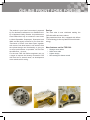
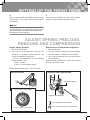
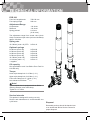
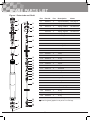
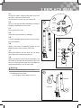
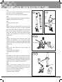
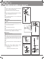
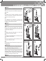
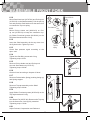
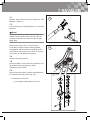
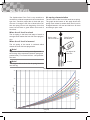
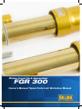
Öhlins Front Fork Superbike
FGR 300
Owner’s Manual/ Spare Parts List/ Workshop Manual
INTRODUCTION
Congratulations! You are now the owner of an
Öhlins Front Fork. More than two hundred World
Championships and other major world titles are
definitive proof that Öhlins products offer outstanding performance and reliability.
Every product has gone through rigorous
testing and engineers have spent thousands of
hours, doing their very best to use every possible
experience from our 30 years within the racing
sport. The product that you now have in your
possession is pure racing breed that is built to
withstand.
It was the 1970’s, a young man named Kenth Öhlin spent most of his spare time pursuing his favourite sport: motocross.
A careful
observer,
Kenth’s
attention
was continually drawn to one specific
detail - motocross bikes had more engine
power than their suspension could handle.
It was not long before Kenth realised that better
performance could be achieved by improved
wheel suspension.
Öhlins Racing was established in 1976, and just
two years later the company won its first World
Championship title. Despite being in the business
for 30 years, the search for perfection and new
functions is still the main focus of the company.
By installing this front fork on your bike you have
made a clear statement… you are a serious rider with a focus on getting the maximal handling
ability and outstanding feedback from your bike.
Along comes the fact that your front fork will be a
long lasting friend, delivering the very best of comfort and performance every time you go for a ride.
Go explore!
1
SAFETY PRECAUTIONS
General Warnings
SAFETY SYMBOLS
In this manual, mounting instructions and
other technical documents, important information concerning safety is distinguished by
the following symbols:
Note!
The shock absorber/front fork/steering damper is
an important part of the vehicle and will affect the
stability.
Note!
Read and ensure you understand the information in this manual and other technical documents
provided by Öhlins, before using the product.
The Safety Alert Symbol means: Warning!
Your safety is involved.
Warning!
Note!
The Warning Symbol means: Failure to follow warning instructions can result in severe or fatal injury to anyone working with,
inspecting or using the shock absorber, or
to bystanders.
Warning!
The Caution Symbol means: Special precautions must be taken to avoid damage to
the shock absorber.
Warning!
The Note Symbol indicates information that
is important regarding procedures.
Öhlins Racing AB can not be held responsible
for any damage to the shock absorber/front fork/
steering damper, vehicle, other property or injury
to persons, if the instructions for mounting, usage
and maintenance are not followed exactly.
Caution!
After installing the Öhlins product, take a test ride
at low speed to ensure your vehicle has maintained stability.
Note!
If the suspension makes an abnormal noise, or
the function is irregular, or if you notice any leakage from the product, stop the vehicle immediately and return the product to an Öhlins Service
Centre.
Product Specific Warnings
Warning!
Warning!
The product warranty shall only apply if the product has been operated and maintained in accordance with recommendations in this manual. If you
have any questions regarding usage, service,
inspection and/or maintenance please contact
Öhlins.
This product was developed and designed exclusively for a specific vehicle model and shall only
be installed on the intended vehicle model in its
original condition as delivered from the vehicle
manufacturer.
Warning!
Note!
This product contains pressurized nitrogen
gas (N2). Do not open, service or modify this
product without proper education (authorized Öhlins dealer/distributor) and proper tools.
When working with the Öhlins product, always
read the Vehicle Service Manual.
Note!
This Manual shall be considered a part of the
product and shall therefore accompany the product throughout its life cycle.
© Öhlins Racing AB. All rights reserved. Any
reprinting or unauthorized use without the written
permission of Öhlins Racing AB is prohibited.
2
CONTENTS
Introduction.................................................................. 1
Safety Precautions....................................................... 2
Öhlins Front Fork FGR300........................................... 4
Setting up the Front Fork............................................. 5
Adjust Spring Preload, Rebound and Compression..... 6
Technical Information................................................... 7
Spare Parts List........................................................... 9
Workshop Section...................................................... 13
Tools..................................................................... 14
1 Replace Spring.................................................. 15
2 Disassemble Front Fork.................................... 16
3 Replace Seal..................................................... 18
4 Replace Inner/Outer tube.................................. 19
5 Disassemble Shaft............................................. 21
6 Assemble Front Fork......................................... 22
7 Revalve............................................................. 24
Oil level . ................................................................... 25
Troubleshooting......................................................... 26
3
ÖHLINS FRONT FORK FGR 300
Design
The product in your hand is an artwork, prepared
by our dedicated craftsmen at our Swedish facility in Upplands Väsby, Sweden. Its predecessors
have battled their way on numerous race tracks
in World Superbike, Supersport, Superstock and
AMA, and the legacy continues in your front fork.
Thousands of hours have been spent together
with some of the best teams in the world to find
the optimal design and functionality to give you
as much performance as possible. You will feel
the difference…be sure.
For the new FGR 300 Öhlins engineers set out
a target to improve the already successful FGR
200 front fork in several areas, as development
never stands still in racing.
The outer tube is now reinforced making the
FGR 300 stiffer and more robust.
This pressurized front fork, equipped with 25mm
TTX technology is the very latest in front fork technology.
New features on the FGR 300
•
•
•
•
4
Stronger outer tubes
Stiffer outer tube
Lighter design
New settings for better control
SETTING UP THE FRONT FORK
2 Check Ride Height
Note!
The front fork is just one part of your motorcycle.
To make it work properly, set up your motorcycle
according to your vehicle service manual.
Note!
The following procedure should be performed on
a flat surface. We recommend that the following
procedure should be performed by two persons.
1 Mount Öhlins Front Fork
Put your motorcycle on a workstand and mount
the Öhlins front fork with the splines facing out
from the motorcycle (see figure below). Follow instructions in your vehicle service manual.
Lower triple clamp;
Tightening torque max. 12-15Nm
2.1
Put the motorcycle on a stand.
Ensure that the shock absorber is fully extended.
2.2
Measure the distance from a point marked by a
piece of tape, immediately above the rear wheel
axle, to the wheel axle (R1).
Caution!
If the Steering damper bracket is located around
the upper front leg, do not exceed 12-15Nm. Too
high torque may deform the front fork leg, affecting the function negatively.
2.3
Make a similar measurement on the front axle, for
example, from the bottom of the upper triple clamp
to a fixed point, for example the front wheel axle
(F1). Make sure that the front fork is fully extended.
2.4
Put the motorcycle on the ground so that the front
and the rear suspensions are slightly compressed.
Repeat the measuring procedures (R2 and F2).
2.5
Sit on the motorcycle in normal riding position,
properly outfitted in your riding gear. Correct riding position is important so that the weight is balanced on the front and rear wheel in the same way
as when riding. Repeat the measuring procedure
(R3, F3).
Note!
See Chapter “Technical Information” for technical
data for the FGR 300.
2.2 2.3
3
The measurements should not differ from the following:
Rear 30±5 mm (R1-R3)
Front 35±5 mm (F1-F3)
2.4
2.5
5
SETTING UP THE FRONT FORK
4
5
If the measures differ significantly from the measures in step 3, you need to set the spring preload
(see below).
If the measures still differ, you may need to change
spring. Contact an Öhlins dealer for advice.
Note!
The spring preload is very important since it affects the height of the motorcycle and the fork angle. Consequently, handling characteristics can
be changed, even negatively.
ADJUST SPRING PRELOAD,
REBOUND AND COMPRESSION
Adjust Spring Preload
Rebound and Compression Adjusters
1. Use a 14 mm wrench.
2. Turn the nut on the top of the fork leg. Turn
clockwise to increase spring preload, turn
counter clockwise to decrease it. 1 turn on the adjustment nut will change
spring preload 1 mm.
1 turn = 2 “clicks”
1 “click” = ½ mm spring preload
1. Use tool 00794-01
2. Turn the adjuster screw(s) at the fork bottom.
Turn the adjuster clockwise to fully closed.
3. Turn counter clockwise and count the clicks to
set the adjuster. Recommended adjustment “clicks” from closed
position: See spec. card
Recommended static sag (F1-F2): 25-30 mm
Spring Preload
Rebound and Compression
Rebound Adjuster
1 turn = 2 clicks = 1mm change
Compression Adjuster
Turn clockwise to close valve
Turn counter clockwise to open valve
½ turn = 1 click = ½mm change
6
TECHNICAL INFORMATION
FGR 300
Front fork length/stroke
Free spring length 750/130 mm
260 mm
Adjustment Range
Compression
~26 clicks
Rebound
~26 clicks
Spring preload
0-18 mm
(0-18 turns)
The adjustment range from closed valve (clockwise) to maximum open valve (counter clockwise):
approx. 26 clicks
Spring rate
10.0 N/mm (mark -10) STD
04744-10
Optional springs
8.0 N/mm (mark -80) 8.5 N/mm (mark -85) 9.0 N/mm (mark -90) 9.5 N/mm (mark -95) 10.5 N/mm (mark -05) 11.0 N/mm (mark -11)
* supplied
04744-80 04744-85 04744-90 04744-95* 04744-05*
04744-11*
Oil capacity
See specification card. Use Öhlins Front Fork fluid 01309 only.
Torque
Lower triple clamp bolt 12-15 Nm (1-2-1)
Upper triple clamp bolt 18-22 Nm (1-2-1)
Front axle Clamp bolt 17-19 Nm (1-2-1)
Axle tolerances Ø 30mm -0.02/-0.06
Note!
If your vehicle also is equipped with an Öhlins
Steering Damper outer tube clamp;
Tighten to: 12-15Nm
Service intervals
This product is designed for racing use only.
Service and maintenance is recommended every 20 hours.
Disposal
Discarded products should be handed over
to an authorized Öhlins Service Centre for
proper disposal.
7
TECHNICAL INFORMATION
8
SPARE PARTS LIST
Figure 1 Outer tube and Shaft
1
2
9
10
3
5
13
14
4
6
8
Pcs
Description
Notes
04732-11
2
Top nut assembly
See page 11
1-2
03316-02
2
Spring support
1-3
04744-10
2
Spring, installed
25.5/260/10.0
04744-95
2
Spring, supplied
25.5/260/9.5
04744-05
2
Spring, supplied
25.5/260/10.5
04744-11
2
Spring, supplied
25.5/260/11.0
1-4
01438-04
4
Guide ring
1-5
01460-35
2
Preload tube
169 mm
1-6
01900-13
2
Outer tube
510 mm
1-7
01683-04
2
Bushing, upper
1-8
01684-04
2
Bushing, lower
1-9
04758-01
2
Washer
1-10
04720-02
2
Seal
1-11
04759-01
2
Circlip
1-12
01901-08
2
Shaft extension
15
16
1-13
00338-76
2
O-ring
1-14
21666-01
2
Guide sleeve
17
18
19
20
21
1-15
01582-22
2
Spacer
1-16
01580-04
2
Bump rubber
1-17
01651-15
2
Seal head
1-18
00438-02
2
O-ring
22
23
1-19
15428-01
2
Seal
1-20
01056-09
2
Bushing
24
1-21
01582-24
2
Spacer
1-22
00638-81
2
O-ring
1-23
01653-09
2
Sleeve
1-24
21733-03
2
Top-out spring
1-25
21734-01
2
Shaft
1-26
00338-39
2
O-ring
1-27
02061-07
2
TTX-piston
1-28
00638-25
2
O-ring
1-29
01447-02
2
Piston ring
25
7
Part No
1-1
11
12
4
Pos
26
27
15 mm
525.5 mm
Ø 25 mm
Note! Pcs [pieces] applies for one pair of Front Fork legs
28
29
9
SPARE PARTS LIST
Figure 2 Inner tube and Fork Bottom
Pos
1
2
3
4
5
6
22
23
24
25
26
27
Part No
Pcs
Description
04809-04
2
Cylinder tube ext
2-2
00438-75
2
O-ring
2-3
00576-11
2
O-ring
2-4
04807-04
2
Vol. Spacer
2-5
01656-14
2
Cylinder tube
158mm
2-6
01703-02
2
Inner tube
528mm
2-7
01565-04
1
Stroke indicator
Right
2-8
00338-54
1
O-ring
Green
2-9
04759-02
2
Circlip
2-10
01682-55
2
Fender bracket ring
2-11
01678-14
2
Fender bracket
2-12
00382-08
2
Screw
2-13
00338-63
2
O-ring
2-14
01902-29
1
Fork bottom
Left
01902-30
1
Fork bottom
Right
2-15
01240-08
4
Screw
Titanium
2-16
04810-01
2
Stop screw
2-17
00382-07
2
Screw
2-18
00438-33
2
O-ring
2-19
01669-02
4
Caliper sleeve
2-20
01669-03
4
Spacer
Optional
2-21
-
2+2
Valve assy
See fig 4
2-22
01050-01
2
Screw
28
29
7
2-23
00338-59
2
O-ring
8
2-24
00557-01
2
Circlip
30
9
2-25
00338-25
2
O-ring
2-26
00161-12
2
Reservoir end assy
2-27
02806-01
2
Gas piston
2-28
01447-02
2
Piston ring
2-29
00338-25
2
O-ring
2-30
02814-03
2
Reservoir tube
2-31
00338-72
2
O-ring
12
10
31
17
21
18
19 20
16
11
13
14
15
19
Notes
2-1
95 mm
Note! Pcs [pieces] applies for one pair of Front Fork legs
20
10
SPARE PARTS LIST
Figure 3 Top Cap Assembly
2
3 4
5
6
7
1
Pos
Part No
Pcs
Description
3-1
04732-11
2
Top Cap Assy
3-2
03312-09
2
Adjuster
3-3
03083-01
4
Spring
3-4
00884-06
4
Ball
3-5
00338-72
2
O-ring
3-6
03309-01
4
Thin Shim
3-7
03318-11
2
Housing
3-8
00338-02
2
O-ring
3-9
03317-01
8
Spring washer
3-10
03313-01
2
Nut
3-11
03315-05
2
Preload socket
8
Notes
Note! Pcs [pieces] applies for one pair of Front Fork legs
6
9
10
11
11
SPARE PARTS LIST
Figure 4 Valve
1
2
3
4
5
6
7
8
9
10
Pos
Part No
Pcs
Description
Notes
4-1
01657-01
4
Nut
Aluminium
4-2
00153-01
4
Washer
4-3
01672-01
4
Spring collar
4-4
-
-
Spring
4-5
01669-04
4
Sleeve
4-6
-
-
Shim
4-7
02406-02
4
Piston
4-8
00338-11
4
O-ring
4-9
-
-
Shim stack
See spec. card
4-10
-
-
Clamp washer
See spec. card
4-11
01658-09
2
End piece
Compression
01658-10
2
End piece
Rebound
4-12
00438-02
4
O-ring
4-13
01242-16
4
Adjustment needle
4-14
00884-02
8
Ball
4-15
01474-01
4
Spring
4-16
00338-53
4
O-ring
4-17
01473-02
4
Circlip
See spec. card
See spec. card
ø2,5 mm
Note! Pcs [pieces] applies for one pair of Front Fork legs
11
12
15
14
14
13
16
17
12
WORKSHOP SECTION
Tools ....................................................................... 14
1 - Replace Spring..................................................... 15
2 - Disassemble Front Fork........................................ 16
3 - Replace Seal........................................................ 18
4 - Replace Inner/Outer tube..................................... 19
5 - Disassemble Shaft................................................ 21
6 - Assemble Front Fork............................................. 22
7 - Revalve................................................................. 24
13
TOOLS
Pos
Part No
Description
1
00146-01
Öhlins red grease
Notes
2
00147-01
Öhlins white grease
3
00715-01
Sharp screw driver
4
00720-02
Measure pin
5
00720-03
Pin tool
6
00727-08
Soft jaws
7
00786-05
Soft jaws clamp
ø 43
00786-07
Soft jaws clamp
ø 29
8
00794-01
Screwdriver Allen key
3 mm
9
00797-08
Sleeve pin
10
01309-01
Öhlins Front Fork fluid
11
01757-01
Attachment bar tool
12
01758-04
Bar guide
13
01759-07
Bushing tool
Dismantling
01759-08
Bushing tool
Installation
14
01765-03
Pull up tool
15
01781-01
Gas filling device
16
01797-04
Seal head tool
17
01797-07
Seal head tool
18
02810-01
Pull up holder tool
19
00159-02
Functional grease
19
00159-02
Assembly grease
3
4
5
6
7
8
9
10
11
14
12
Heat gun
3/8’’
Loctite 648
Loctite 222
Loctite 2701
Rag
Teflon tape
Torx wrench
2
13
Brass wire brush
Torque Wrench
1
T20
Vice
Waste fluid container
Wire with hook
Wrench
14 mm
Wrench
17 mm
Wrench
19 mm
Wrench
20 mm
14
15
16
18
19
17
1Note!
REPLACE SPRING
This procedure can be performed with the front
fork on the vehicle, front wheel off the ground.
1.1
1.1
Release spring preload. Use a 14mm wrench.
Turn the Adjustment nut counter clockwise until
stop, make a note of position.
Caution!
Do not use the Preload adjuster to tighten or
loosen the Top cap assembly.
1.2
1.2
Loosen the screws attaching the fork legs in the
upper triple clamp.
1.3
Loosen Top cap assembly from the Outer tube.
Use Sleeve Pin tool (00797-08), lower the front so
that the front fork is fully compressed.
1.4
1.3
1.4
Tool 00797-08
Remove Top cap assembly from the Shaft.
Use a 14 mm wrench on the top cap and a
19 mm wrench on the Shaft.
1.5
1.5
Remove Spring support and Spring. Use a wire
with a hook and carefully pull up Preload tube.
1.6
Check oil level according to Chapter Oil level.
1.7
Remount Preload tube, new Spring (marking facing up) and Spring support.
1.8
Remount the Top cap assembly on the Shaft. Tightening torque 20 Nm.
1.9
Apply Öhlins Functional grease (00159-02) on the
Top cap thread and O-ring.
1.10
Remount Top cap into the outer tube, with the fork
fully extended. Use Sleeve Pin tool (00797‑08).
See figure 1.3
Tightening torque 10 Nm.
1.8
1.11
Tighten the upper triple clamp and reset the
preload, see page 5.
15
2 DISASSEMBLE FRONT FORK
2.1
Loosen the upper clamp screws and loosen the
top cap ½ turn use tool 00797-08.
Remove the Front fork from the motorcycle.
2.3
2.2
2.2
Fasten the Fork leg in a vice with soft jaws.
2.3
Release spring preload. Use a 14 mm wrench.
Turn the Adjustment nut counter clockwise until
stop, make a note of position.
Caution!
Do not use the Preload adjuster to tighten or
loosen the Top cap assembly.
2.4
Loosen Top cap assembly from the Outer tube.
Use Sleeve Pin tool (00797-08), push down the
outer tube.
2.4
2.5
Remove Top cap assembly from the Shaft.
Use a 14 mm wrench on the top cap and a
19 mm wrench on the Shaft.
Tool 00797-08
2.6
Remove Spring support and Spring. Use a wire
with a hook and carefully pull up Preload tube.
2.5
2.6
2.7
Remove Screw and O-ring from the Reservoir
end. Use a Torx wrench T20.
2.8
Count and note Adjuster settings. open the Adjusters to fully open.
2.7
Reservoir
end
16
2 DISASSEMBLE FRONT FORK
Warning!
Releasing high pressure gas can be hazardous.
Do not perform any kind of service until gas pressure is completely released.
2.9
2.10
2.9
Release gas pressure. Insert tool 01781-01 in the
Reservoir end through the Rubber membrane.
2.10
Use Pin tool (00720-03). Press the Reservoir
end down to remove the Circlip, clean the circlip
groove with a rag.
2.11
Remove the Reservoir end. Use Pin tool (0072003).
2.11
2.12
Remove Shaft assembly from the fork leg.
Use Seal Head tools (01797-04 and 01765-03).
2.12
2.13
Drain all oil from the fork leg.
2.14
Tool
01765-03
Remove Gas piston. Use Measure Pin (0072002).
Tool
01797-04
→ To Replace Seal
go to Chapter 3 Replace Seal.
→ To Disassemble Shaft assembly
go to Chapter 5 Disassemble Shaft.
2.13
Shaft
assembly
2.14
Gas
piston
17
3 REPLACE SEAL
3.1
Loosen the upper clamp screws and loosen the
top cap ½ turn use tool 00797-08.
Remove the Front fork from the motorcycle.
3.5
3.2
3.3
Circlip
Remove Top cap and Shaft assembly according to
Chapter 2 Disassemble Front Fork.
Seal
3.3
Washer
Remove the Outer tube.
3.4
Clean the Seal and check for damage.
3.5
If seal is damaged replace by removing the circlip,
Seal and Washer.
3.6
3.6
Apply a thin layer of Assembly grease on the
Washer and the outer surface of the Seal.
Circlip
3.7
Mount the Washer and the Seal into the Outer
tube. Mount the circlip into the groove.
Seal
3.8
Washer
Apply some Öhlins Front Fork fluid (01309-01) on
the inside of the seal and the outside of the inner
tube, do not use grease inside the seal. Slide the
Outer tube carefully on to the Inner tube.
Warning!
Be careful - Not to damage the Fork seal!
3.8
→ To reassemble Front Fork
go to Chapter 6 Assemble Front Fork
Outer tube
Inner tube
18
4 REPLACE INNER/OUTER TUBE
4.1
Loosen the upper clamp screws and loosen the
top cap ½ turn use tool 00797-08.
Remove the Front fork from the motorcycle.
4.3
4.4
4.2
Inner
tube
Remove Top cap and Shaft assembly according to
Chapter 2 Disassemble Front Fork.
4.3
Ø 5 mm oil
bleed hole
Remove the Outer tube.
4.4
Mount clamp tool (00786-05) on the Inner tube
(Make sure both are clean), as high as possible
above the lower ø5 mm oil bleed hole. Use a heat
gun to heat up the fork bottom. Loosen and remove the Inner tube. Clean the thread from all
Loctite. We recommend to replace the O-ring
(00338-63).
Tool
00786-05
Outer
tube
4.5 4.6
4.5
Loosen and remove the Reservoir tube. Use
Clamp tool (00786-07), Use a heat gun to heat
up the fork bottom. Clean the thread thoroughly
from Loctite. We recommend to replace the O-ring
(00338-72).
Tool 00786-07
4.6
Mount the new Reservoir. Using clamp tool
(00786‑07).
Loctite 222 (on the thread)
Tightening torque 25 Nm
4.7 4.8
4.7
Mount the new Inner tube. Use clamp tool (0078605) and make sure both tool and tube are clean.
Install the tool as high as possible above the lower
ø 5 mm oil bleed hole. Apply Assembly grease on
the O-ring on the Cylinder tube extension.
4.8
Loctite
Apply a thin layer of Öhlins Front Fork fluid (01309‑01) on the inside of the Inner tubes lower half. Carefully slide the Inner tube over the Oring and on the Fork bottom thread.
Loctite 2701 (on the threads)
Tightening torque 160 Nm
19
4 REPLACE INNER/OUTER TUBE
4.9
Apply some Öhlins fork fluid (01309-01) on the Inner tubes outer surface and inside the seal, do not
use grease inside the seal. Slide the Outer tube
carefully on to the Inner tube.
4.9
Warning!
Be careful - Not to damage the Fork seal!
Outer tube
→ To reassemble Front Fork
go to Chapter 6 Assemble Front Fork
Inner tube
20
5 DISASSEMBLE SHAFT
5.1
Loosen the upper clamp screws and loosen the
top cap ½ turn use tool 00797-08.
Remove the Front fork from the motorcycle.
5.3
5.2
Remove Top cap and Shaft assembly according to
Chapter 2 Disassemble Front Fork.
5.3
Put the Shaft assembly in a vice. Use Soft Jaws
Clamp (00727-08).
Caution!
Do not tighten the jaws too hard, the Shaft can be
damaged.
5.4
Remove Piston, Top-out spring and Sleeve in one
unit. Use a 20 mm wrench.
Piston
Top-out spring
5.5
Remove Spacers and O-ring.
5.4
5.6
Remove the Seal head from the Shaft. Check the
Seal and the O-ring. Replace if necessary.
5.5 Sleeve
Spacer
O-ring
Caution!
Do not use sharp tools.
5.7
Wrap Teflon tape around the Shaft thread (to protect the Seal). Apply Assembly grease on the tape
and the Shaft end. Remount the Seal head on the
shaft.
5.6
Seal head
O-ring
Seal
Bushing
5.8
Use a brass wire brush to clean the Shaft from
tape.
5.9
Remount the O-ring, Spacer, Sleeve, Top-out
spring and Piston. Use a 20 mm wrench.
Loctite 243
Tightening torque (piston) 10 Nm
5.7
21
5.8
5.9
6 ASSEMBLE FRONT FORK
Note!
Use Öhlins Vacuum Filling Machine for best result.
6.2
6.1
6.3
Open the Compression and Rebound adjusters to
fully open.
6.2
Fill Öhlins Front Fork fluid (01309‑01) up to the
edge of the Reservoir. Carefully continue to fill until the oil level does not drop.
Gas piston
6.3
6.1
Use Measuring Pin (00720-02). Carefully push
the Gas piston, with the Teflon band and O-ring
installed, to the Reservoir bottom.
Note!
Ensure that there is no air between the Piston
and the oil.
6.4
6.5
6.4
Fill the inner tube with Öhlins Front Fork fluid
(01309‑01) to approximately 20‑30 mm above the
cylinder tube extension.
2030mm
6.5
Carefully pump the Gas piston up and down
10‑20 times to bleed the system.
6.6
Check the O-ring (00338-25) on the Reservoir end
cap. Replace if necessary.
6.7
Use Pin tool (00720-03). Mount the Reservoir end
cap into the Reservoir tube.
6.8
6.7 6.8
Remount the Circlip. Ensure that it stops in the intended groove.
Warning!
Use nitrogen gas (N2) only! Using inflammable
gas to pressurize the front fork can be hazardous. Use Pressure Gauge (01781-01).
6.9
Dip the needle of Pressure Gauge (01781-01) in
Assembly grease and insert the needle through
the Gas filler valve. Charge with gas to the correct
pressure, according to the spec. card.
Note!
Ensure that there is no leakage of gas or fluid.
22
6.9
6 ASSEMBLE FRONT FORK
6.10
Tool 01765-03
6.10
Mount Seal Head tool (01797-04) and Pull-up tool
(01765-03) on the Shaft assembly. Pull the pull-up
tool and push the Seal head tool at the same time
to contract the Top-out spring.
6.11
6.12
Tool 02810-01
6.11
Mount Pull-up Holder tool (02810-01) on Pullup tool (01765-03) to keep the contraction. Apply Öhlins Functional grease (00159-02) on the
Seal head thread and the O-ring.
Tool
01797-04
6.12
Insert the Shaft assembly all the way down into
the Cylinder tube. Tighten by hand.
6.13
Top-out
spring
6.13
Check Gas pressure again according to the
spec. card.
6.14
Tighten the Gas filling screw and O-ring
Tightening torque 3 Nm
6.15
6.15
Remove Pull-up Holder tool and Pull-up tool.
Use tool Seal Head tool (01797‑07).
Tightening torque 20 Nm
Tool 01797-07
6.16
Check oil level according to chapter Oil level.
6.17
6.17
Remount Preload tube, Spring (marking facing up)
and Spring support.
6.18
Remount Top cap assembly on the Shaft.
Tightening torque 20 Nm
6.19
Apply Öhlins Functional grease (00159-02) on the
Top cap thread and O-ring.
6.18
6.20
Use Sleeve Pin (00797-08). Remount the Top cap
into the Outer tube, fork leg fully extended.
Tightening torque 10 Nm
6.21
Adjust Preload, Compression and Rebound.
23
7 REVALVE
7.1
7.2
Release Gas pressure from the Reservoir. See
Chapter 2, step 2.9.
7.2
Put the fork leg in horizontal position, in a vice with
soft jaws.
Note!
Do not mix up the two valves, they must be installed in their intended valve housing. We recommend to remove one valve at a time to keep
them apart.
7.3
Remove one Valve. Use a 17 mm wrench.
If you only intend to change setting without
changing oil, please make sure to fill oil at the
same time as you remove the valves, if not you
can get an air trap below the adjuster.
7.3
7.4
Perform necessary service.
7.5
Add some Öhlins Front Fork fluid (01309-01) into
the Valve housing. Remount the Valve.
Tightening torque 20 Nm
7.6
Remove the other Valve. Perform necessary service. Remount the Valve (see step 7.5).
x2
→ To pressurize Front Fork
go to Chapter 6 Assemble Front Fork
24
OIL LEVEL
Air spring characteristics
The Upside-down Front Fork is very sensitive to
variations in oil level compared to the conventional
type fork. Therefore, adjust the oil level with special care. A change in the fork oil level will not affect the spring force at the beginning of the fork
travel, but will have a great effect at the end of
the travel.
The air inside of the front fork works as a spring.
The graph at the bottom of this page shows the
spring force related to stroke when the oil level is
changed between 100 mm and 260 mm. Oil level
according to spec. card.
When the oil level is raised
The air spring in the later half stage of travel is
stronger which makes the front fork more progressive.
Push to a stop.
Use tool 01765-03
Öhlins Front fork
fluid 01309-01
When the oil level is lowered
The air spring of the travel is reduced which
makes the front fork less progressive.
Note!
The edge of the
outer tube
Adjust the oil level according to the figure with
the fork leg fully compressed (without spring and
preload tube). For correct oil level - see specification card.
Note!
Oil level
The diagram below shows the air spring force for
one fork leg.
Force vs Stroke
250
200
150
160
170
180
150
190
Force [N]
200
210
220
230
100
240
250
260
270
50
0
0
10
20
30
40
50
60
70
Stroke [mm]
25
80
90
100
110
120
130
TROUBLESHOOTING
Troubleshooting
2
The whole motorcycle setup affects the front fork.
Make sure you understand how the front fork
works, and make adjustments step by step.
The front wheel is jumping during the last part of
braking.
Try one of the following
→→ If a lot of stroke remains, the oil level is too
high. Lower the oil level.
→→ If the fork is bottoming, install harder springs
and keep the oil level.
Note!
Adjust only one thing at a time.
Below you will find a few examples of how to adjust for the most common stability problems in
Road Racing driving.
3
The front end feels unpredictable and unsafe in
the middle of the corner (between braking and getting on power).
1
The front wheel “chatters” entering a corner, the
problem goes away, as soon as you let the brakes
off, or when you get on the power.
Try one of the following
→→ Not enough rebound damping. Add more
damping.
→→ Too much rebound damping. If it at the same
time feels harsh, reduce rebound damping.
→→ Too much compression damping. Also gives a
harsh feeling. Reduce compression damping.
A
The fork is working too low in the travel and reaches the progressive, hard part at the end of the travel.
Try one of the following
→→ Increase preload.
→→ Change to a harder spring.
→→ If a lot of stroke remains after riding, drop the
oil level. See oil level chart.
→→ Make sure the front fork has no friction.
4
The front end loses grip coming out of a corner.
Try one of the following
→→ Not enough rebound damping. Add more rebound damping.
→→ Too much preload. Reduce preload.
→→ Rear end is too soft. Install harder rear spring.
→→ Front end is too high. Lower the front end by
pulling the fork legs through the triple clamps.
B
Rear ride height is too high, too much rear spring
preload.
Try one of the following
→→ Lower the rear end by taking off preload from
rear shock spring.
4
1
26
Öhlins Owner’s Manual FGR300 | Part No. 07280-20_0 | Issued 2012-12-04 | © Öhlins Racing AB
Your Öhlins retailer:
Öhlins Racing AB
Box 722
SE-194 27, Upplands Väsby
Sweden
Phone: +46 (0)8 590 025 00
Fax: +46 (0)8 590 025 80
www.ohlins.com