1
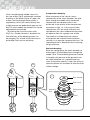
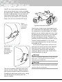
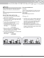
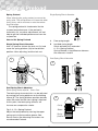
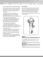
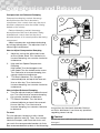
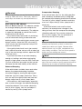
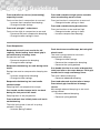
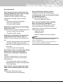
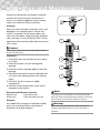
Shock Absorber for ATV
Owner’s Manual
Introduction
Öhlins Racing AB - The Story
It was the 1970’s, a young man named Kenth
Öhlin spent most of his spare time pursuing his
favourite sport: motocross.
A careful observer, Kenth’s attention was
continually drawn to one specific detail motocross bikes had more engine power than
their suspension could handle.
It was not long before Kenth realised that better
performance could be achieved by improved
wheel suspension.
Öhlins Racing was established in 1976, and
just two years later the company won its first
World Championship title. Despite being in the
business for 30 years, the search for perfection
and new functions is still the main focus of the
company.
Congratulations! You are now the owner of an
Öhlins Shock Absorber. More than one hundred
World Championships and other major world
titles are definitive proof that Öhlins shock
absorbers offer outstanding performance and
reliability.
Every product has gone through rigorous
testing and engineers have spent thousands of
hours, doing their very best to use every possible
experience from our 30 years within the racing
sport.
The product that you now have in your
possession is pure racing breed that is built to
withstand.
By installing this shock absorber on your
vehicle you have made a clear statement…
you are a serious rider with a focus on getting
the maximal handling ability and outstanding
feedback from your vehicle. Along comes the
fact that your shock absorber will be a long
lasting friend, delivering the very best of comfort
and performance every time you go for a ride.
Go explore!
Safety Precautions
Note!
Safety Symbols
The shock absorber is a very important part of
the vehicle and will therefore affect the stability.
Read and make sure that you understand
the information in this manual and the mounting
instructions before you use this product. If you
have any questions regarding installation or
maintenance please contact your nearest
Öhlins dealer.
In this manual, mounting instructions and
other technical documents, important
information concerning safety is
distinguished by the following symbols:
The Safety Alert Symbol means: Warning!
Your safety is involved.
Öhlins Racing AB can not be held
responsible for any damage to the shock
absorber, vehicle, other property or injury to
persons, if the instructions for installing and
maintenance are not followed exactly.
Warning!
The Warning Symbol means: Failure to
follow warning instructions can result in
severe or fatal injury to anyone working with,
inspecting or using the shock absorber, or
to bystanders.
Warning!
This product was developed and designed
exclusively for a specific vehicle model and
should only be installed on the intended vehicle
model in its original condition as delivered from
the vehicle manufacturer.
Caution!
The Caution Symbol means: Special
precautions must be taken to avoid damage
to the shock absorber.
Note!
This product contains pressurized nitrogen
gas (N2). Do not open, service or modify this
product without proper education (authorized
Öhlins dealer/distributor) and proper tools.
The Note Symbol indicates information that
is important regarding procedures.
After installing this product, take a test ride
at low speed to make sure that your vehicle
has maintained its stability.
Note!
When working on this product, always consult
your Vehicle Service Manual.
This Manual should be considered as a part
of the product and should therefore
accompany the product throughout its life
cycle.
© Öhlins Racing AB. All rights reserved. Any
reprinting or unauthorized use without the written
permission of Öhlins Racing AB is prohibited.
Printed in Sweden.
Contents
Introduction
Safety Precautions
Contents
Design
Functioning
Design - TTX
Functioning - TTX
General Set-up
Check Sag and Ride Height
Spring Preload
CSC - Chassis Stability Control
Compression and Rebound
Setting up your Vehicle
General Guidelines
Inspection and Maintenance
Page
1
2
3
4
5
6
7
9
10
11
12 13
14
15
17
Design
Most of Öhlins suspensions are a high pressure
monotube type. The fluid is put under gas
pressure and the gas and the fluid are kept
apart by a separating piston.
The piston is usually fitted in an external
reservoir, connected by a hose (Fig. 1.1) or
fixed directly on top of the shock absorber,
Piggyback (Fig 1.2). There are also models
where the separating piston is fitted inside the
main shock absorber, Internal gas reservoir
(Fig 1.3).
The most advanced shock absorber model
has two pistons to obtain a progressive
damping system (PDS) (Fig 1.4). This ensures
position sensitive damping in relation to the
degree of compression. One piston is active
throughout the entire stroke length, while the
second piston is activated when the shock
absorber is subject to powerful compression.
The fluid is pressurized with nitrogen. The
pressurisation prevents cavitation of the fluid
and the shock absorbing action is therefore
more even. The external reservoir also
contributes to better cooling of the fluid, giving
longer service life for the fluid as well as the
components.
Öhlins shock absorbers have an integrated
temperature compensation.
As the temperature increases and the
fluid flows more easily the flow is controlled
accordingly. The shock absorbing effect is
therefore independent of the temperature.
The advanced shock absorber models
permit individual adjustment of compression
and rebound damping, making them adaptable
to most vehicles, drivers and ranges of use.
All of the shock absorbers with springs have
adjustable preload of the spring action.
1
3
2
4
N2
Fluid
Fluid
Separating
Piston
N2
PDS
Piston
Functioning
Compression damping
When movement of the vehicle causes
compression of the shock absorber, the fluid
flows through the needle valve (combined
compression and rebound valve) in the
piston rod. If the velocity of the compression
movement is high, i.e., in the case of rapid
compression, this will not be sufficient and
consequently the shims underneath the piston
will open to allow for a greater rate of flow.
The fluid that is displaced by the volume
of the piston rod is forced into the external
reservoir via a separate compression valve. The
separating piston is displaced, thus increasing
the gas pressure.
Fluid is forced through needle valves at a
low rate of flow (Fig 5) and through a number
of orifices in the piston (Fig 6) at a high rate
of flow. The flow through these orifices is
regulated by shims (thin steel washers) that
at high pressure are deflected to open for the
fluid. On most models the needle valve can be
adjusted from the outside.
By altering the size of the shim-stack
(Fig 7) (i.e. number, thickness, diameter) the
characteristics of the damping action can
be changed. This should only be done by an
authorized Öhlins service workshop.
5
Rebound damping
When the spring forces the shock absorber to
extend again, the fluid flows back through the
needle valve. The fluid flowing into the chamber
is forced by the pressure of the gas back into
the shock absorber via a separate one way
valve. If the piston velocity is high, the shims on
top of the piston will also open to allow the fluid
to flow through.
6
7
Stop washer
Shim stack
Rebound
flow
Compression
flow
Piston
Design - TTX
The Öhlins TTX shock absorber is the most
unique and powerful racing shock absorber
available today. The TTX shock absorber design
is the culmination of two decades of Öhlins
successful participation in World Championship
events.
The TTX shock absorber is designed to
handle the demanding damping characteristics
needed for all types of tracks, from hard packed
soil to soft sand tracks.
The Öhlins TTX features a patented concept
with a unique twin tube design that allows for
the gas pressure to always back-up the lowpressure side of the piston to keep pressure
at a controlled level. Also the twin tube design
gives the possibility to have totally separated
adjusters for compression and rebound
damping. The CSC adjuster is another benefit, it is an
adjuster that changes the damping force,
balanced and predictable on both compression
and rebound at the same time to control the
chassis stability.
The temperature stability is maintained by using
a flow restriction design in the bleed valves
that create a turbulent flow at very low piston
velocities. Also, materials with different thermal
expansion rates are used to compensate for the
viscosity change of the fluid caused by changes
in temperature.
The Öhlins shim system offers infinite
combinations of shim stacks with a wide
spectrum of different character with one and
the same piston.
The whole system is pressurized by
nitrogen gas behind a floating piston to ensure
separation of the gas and fluid.
The Öhlins TTX shock absorber is a racer
friendly shock absorber, easy to set up, dial in
and rebuild. Support is always available from the
Öhlins distributors worldwide.
Functioning - TTX
Rebound Damping
When the spring forces the shock absorber
to extend again (Fig. 4), the fluid below piston
is pressurized and has to move. In a similar
pattern the flow takes four different routes:
Now it is the volume above piston that
increases and is filled up with flow from piston
rebound shim valve and CSC adjuster bleed
valve. The gas pressure from the reservoir also
pushes fluid into this volume.
The fluid that was displaced into the reservoir
during compression movement is now pushed
back into the main body by the pressure of the
gas.
1. CSC adjuster bleed valve.
2. Piston rebound shim valve.
3. Rebound adjuster bleed valve.
4. Rebound adjuster shim valve.
Fig 3
Fig 4
Functioning - TTX
When the shock absorber moves, the fluid
inside is forced to flow through two types of
orifices. Bleed valves (Fig. 1), small orifices that
create a flow restriction simply by being small
and shim valves (Fig. 2) where fluid pressure has
to deflect thin steel washers (shims) to open up
an orifice and allow fluid flow through it.
To control damping force the bleed valves
can be changed in size by the external
adjusters, CSC, compression and rebound.
By altering the size of the shim stack
(number, thickness, diameter and shape) on the
shim valve the characteristics of the damping
action can be changed.
Note!
Altering the size of the shim stack should only
be performed by an authorized Öhlins service
workshop.
Shim valve flow
Bleed valve
flow
Check valve flow
Compression Damping
When movement of the motorcycle causes
compression of the shock absorber, (Fig. 3) the
fluid above the piston is pressurized and has to
move. It has four different escape routes:
1. CSC adjuster bleed valve.
2. Piston compression shim valve.
3. Compression adjuster bleed valve.
4. Compression adjuster shim valve.
Fluid will at every compression movement use
all these routes but at slow movement speeds
the percentage going through the bleeds is
higher and at fast movement the shim valves
take care of most of the flow.
The volume below the piston increases and
has to be filled up with fluid, if the flow coming
in through the piston compression shim valve
and CSC adjuster bleed valve is not enough
the gas pressure from the reservoir pushes fluid
in via a check valve in the rebound adjuster
valve. During compression movement piston
rod volume is entering the main body and the
corresponding volume
of damper fluid has to
flow into the reservoir,
the separating piston
Fig 1
moves resulting in
an increased gas
pressure.
Fig 2
General Set-up
The ATV has a rear axle but no differential,
which means that turning is mainly managed
by sliding (Fig 8). Therefore, an extremely good
traction is undesiderable. The rear end must
easily break loose to slide, and the turning
radius for the front wheels must not be too
sharp, since this may cause the ATV to tip.
Fig 8
Steering by
sliding the
rear end.
Fig Shock Absorber Position
These factors make it even more important for
the suspension to be adjustable. Any change of
the components mentioned above, will require
different set‑up. Another important issue is that
the performance of the vehicle is also affected
by the technique and skill of the driver and
of course the driving situation. Therefore, it is
extremely hard to recommend a perfect set‑up.
The best recommendation is to try and by
trial and error decide which set‑up is the most
favourable for you.
In this manual we give basic advise on how
to set up your vehicle and the shock absorber.
Read the manual carefully and if you have
any questions about the shock absorber or
setting up, please contact your nearest Öhlins
Authorized Dealer for advise.
Normal vehicle
steering by
turning the
front wheels in
the intended
direction.
Warning!
The ATV is extremely depending on what tires are
being used. The suspension must be tuned in
every time you change tires.
Warning!
Every change in suspension geometry, for example
change A-arms, must be followed by checking the
set‑up for the shock absorber.
The tires are another important factor to the
vehicle’s traction. Pattern, sidewall flexibility
and air pressure affects these characteristics.
Changing the dimension of the A-arms, swing
arm and linkage will therefore affect the
vehicle’s stability.
Check Sag and Ride Height
Warning!
Recommended Measures
Before riding, always ensure that the basic settings
made by Öhlins are intact. Take notes, adjust in
small steps and make only one adjustment at a
time.
Free Sag
General recommendation (If no other measure
given in the Mounting Instructions) 30±5 mm
Step 1
Ride Height
See the Mounting Instructions.
Measure Ride Height and Free Sag
. Put the ATV on a stand so that the wheels
barely touch the ground.
. Measure the separate distances from the top
centre of the axle to a point right above them
on the frame. (F1, R1)
. Put the ATV on the ground and make the
same measurements (F2, R2).
4. The difference between the first and the
second measure is the free sag. Free Sag = F1-F2 (Front)
R1-R2 (Rear)
5. Sit on the ATV in normal riding position,
properly outfitted in your riding gear. Repeat
the measuring procedure (F3, R3).
6. The difference between the first and the third
measure is the ride height.
Ride Height = F1-F3 (Front)
R1-R3 (Rear)
Step 2
. Free Sag: If your measures differ significantly
from the recommendations in the Mounting
Instructions or the recommendation above,
adjust the spring preload. (See chapter
Spring Preload in this manual).
. Ride Height: If the ride height still differs
from the recommendations, you may need to
change to softer/harder spring. Contact your
Öhlins dealer for advice.
10
Spring Preload
Spring Preload
When adjusting the spring preload you move the
spring seat. This will decrease or increase the initial
spring force, which will lower or raise the vehicle
rear ride height.
The spring preload is fundamental for the
suspension performance. If the preload is
incorrectly set, any other adjustments will not
help to get the intended performance from the
suspension.
Single Spring Shock Absorber
A
B
How to Set Spring Preload
A
B
Single Spring Shock Absorber
Use a C-spanner. Unlock the lock nut (1a) and
move the spring platform (1b) to the desired
position. After adjusting, lock the lock nut.
Free spring length
Installed spring length
Shock absorber fully extended
A - B = Spring Preload
Spring Preload is the difference between the measures A and B.
Dual Spring Shock Absorber
1
2
1a
1b
A
Dual Spring Shock Absorber
Short spring stroke adjuster - Cross Over
The total spring characteristics can be adjusted
by moving the spring platforms on the floating
sleeve (3). The spring platform position decides
when the stroke for the short spring is blocked.
At this point, the total spring stiffness will
increase on compression stroke.
B
3
Circlip
Cross over
Fig 2: A - B = Spring Preload
Adjust the total preload by moving the upper
spring seat circlip to another groove. See
Set-up Data in the Mounting Instructions for
recommended Preload.
Sleeve
Spring
platform
11
CSC - Chassis Stability Control
CSC Adjuster
Use an allen key and turn the screw to set the
CSC. Turn clockwise to close the valve and
thereby to increase the damping. Turn counter
clockwise to open the valve, and thereby
decrease the damping. See recommended
Set-up data in the Mounting Instructions for the
shock absorber.
The new unique CSC valve controls the bleed
flow over the main piston. The flow is controlled
in compression as well as rebound stroke and,
due to the TTX function, has particularly high
effect on the low speed movements (chassis
movements).
Since the flow over the main piston is
parallel and not serial to the compression
and rebound adjusters, there is a unique
possibility to separate the over all damping from
compression and rebound damping.
The individually controlled one way valves
in the compression and rebound adjusters
separate the function from the adjusters
and also separate slow speed-long stroke
movements over the main piston.
The CSC valve also controls and
compensates for heat effects. The adjuster
makes sure that temperature changes are under
control and will keep your setup regardless of
weather conditions.
If you are unsure how far you can tune your
TTX shock absorber, start with testing the
CSC valve and you will immediately feel the
differences in over all damping, stability and
chassis movements.
Make sure that spring, spring preload and
CSC valve are correctly adjusted and your fine
tuning will be easy and enjoyable.
Note!
Since the CSC valve is designed to compensate
for temperature changes, the number of clicks will
differ slightly between a cold and a warm shock
absorber. The recommended setting is at room
temperature.
Caution!
Do not use force, delicate sealing surfaces can be
damaged.
12
Compression and Rebound
Compression and Rebound Damping
Compression damping controls the energy
absorption when the shock absorber is
compressed, thus controls how easy the shock
absorber compresses when the wheel is being
loaded or hits a bump.
Rebound damping controls the energy
absorption when the shock absorber is being
extended and controls how fast the shock
absorber returns to its normal position after being
compressed.
Adjust compression and rebound damping
by turning the adjusters. The adjusters have a
normal right hand thread.
1
2
How to Adjust Compression Damping
. Adjust by turning the adjustment knob
on the cylinder head. Turn clockwise to
increase damping, turn counter clockwise
to decrease.
. High and Low Speed Compression
Damping: High speed: Turn the hexagon screw.
Low speed: Turn the slotted centre screw.
Turn clockwise to increase damping, turn
counter clockwise to decrease.
. TTX Shock Absorber; Turn the gold
coloured adjuster on top of the reservoir.
Use an allen key. Turn clockwise to
increase damping, turn counter clockwise
to decrease. 3
5
4
How to Adjust Rebound Damping
4. Turn the adjuster knob just above the end
eye. Turn clockwise to increase damping,
turn counter clockwise to decrease.
5. TTX Shock Absorber; Turn the black
coloured adjuster on top of the reservoir.
Use an allen key. Turn clockwise to
increase damping, turn counter clockwise
to decrease.
Instructions for the shock absorber. Contact
an Öhlins distributor if you have any questions
regarding correct set-up.
To reset
Turn the adjuster clockwise to fully closed
position (position zero [0]). Then, turn counter
clockwise to open, and count the clicks until
you reach the recommended number of clicks.
See recommended Set-up data in the Mounting
Caution!
Do not use force, delicate sealing surfaces can be
damaged.
13
Setting up your Vehicle
Compression Damping
If the vehicle feels soft, has low riding position
and a tendency to bottom easily in long dips
the compression damping should be increased.
Turn four (4) clicks (steps) clockwise and take
a test run. Adjust two (2) clicks (steps) back if
necessary.
If the vehicle feels harsh and has hard
resilience, for example over changes in the
riding surface, then the compression damping
should be reduced. Turn counter clockwise
four (4) clicks (steps). Test run and adjust if
necessary two (2) clicks (steps).
Warning!
Before riding, always ensure that the basic settings
made by Öhlins are intact. Take notes, adjust in
small steps and make only one adjustment at a
time.
Start with the CSC adjuster
Chassis Stability Control. This adjuster controls
the average damping for both compression
and rebound at slow movements. The adjuster
is especially designed to control the chassis
movements of the vehicle.
If the vehicle feels loose and is transferring
a lot of movement during acceleration and
braking and/or if the vehicle feels nervous over
bumpy sections close the CSC valve two [2]
clicks. (If you are close to perfect setup click
one click at the time.
If the vehicle feels hard, harsh (no comfort)
and is difficult to enter corners with or does not
stay in line over bumpy sections, open the CSC
valve two clicks.
If you feel that there is not total damping
enough at landings and when entering big
bumps in high speed, close the CSC valve one
[1] click at the time, be careful so that you do
not loose the feel and stability of the vehicle.
Note!
When you note that the rebound and compression
damping are improved, go back to where you
started and check once again. Observe other
relevant factors such as tires, temperature and
other driving conditions. Test run at low speed to
make sure your settings are correct.
Note!
Make sure that the springs are properly preloaded
before you make any other adjustments. A simple
rule is that an increase of spring preload should be
followed by an increase of rebound damping.
Rebound Damping
If the vehicle feels unstable, loose and rather
bouncy the rebound damping should be
increased. Begin by turning the adjustment
knob four (4) clicks (steps) clockwise. Take a
test run and if the vehicle feels too hard and
bumpy, adjust two (2) clicks (steps) back.
If the vehicle is hard and bumpy, especially
over a series of bumps, the rebound damping
should be reduced. Turn counter clockwise
four (4) clicks (steps), test run and adjust if
necessary two (2) clicks (steps) back.
14
General Guidelines
Front end falls into curves (oversteering),
especialy in sand
Front end too low in comparison to rear end.
- Increase front compression damping.
- Change to harder springs.
Front end unstable at high speed, unstable
when accelerating out of curves
Front end too low in comparison to rear end.
- Change to harder springs in front.
Front end unstable during deceleration
Front end too low or rear end too high
- Change to harder springs in front.
- Increase compression damping.
Front end “ploughs”, understeers
Front end too high in comparison to rear end.
- Decrease the front compression damping.
- Change to softer springs in front.
Front Suspension
Feels harsh over small bumps, but using full
wheel travel.
Too much spring preload or too much
compression damping.
- Change to softer springs.
- Decrease the compression damping.
- Decrease the spring preload.
Suspension travel is not used to its full
capacity. Harsh feeling, front wheel grip is
not satisfactory in bumpy turns.
Suspension too hard.
- Decrease compression damping.
- Change to softer springs.
Suspension bottoming, too soft during entire
travel.
Springs too weak or compression damping too
soft.
- Increase compression damping.
- Change to stiffer springs.
Can handle the first in a series of bumps but
feels hard after a few more bumps. Front grip
insufficient in rough and bumpy turns.
Too much rebound damping.
- Decrease reboound damping.
Front end rebounds too fast after a bump.
Front wheel grip insufficient in bumpy
curves.
Not enough rebound damping, or too much
spring preload.
- Increase rebound damping.
- Decrease spring preload.
Suspension bottoming, but can handle
smaller bumps.
Damping force not progressive enough.
Can handle smaller bumps but is too hard
during the last part of the travel.
Damping force is too progressive.
Front end feels low, initially feels soft, but is
not bottoming.
The initial spring rate is too soft or spring
preload is too low.
- Increase Spring Preload.
15
General Guidelines
Rear Suspension
Rear end becomes too low in series
of bumps. Traction not satisfactory in
washboard type curves or when decelerating
on washboard ground.
Rebound damping too slow.
- Decrease rebound damping.
Rear suspension stroke is not used to its
capacity. Suspension feels harsh. Traction
not satisfactory in bumpy curves.
Suspension hard in general or too much
compression damping, too much spring
preload.
- Decrease compression damping.
- Decrease spring preload.
- Change to softer springs.
Rear end very unstable. Shock absorber
does not respond to adjustments.
Shock absorber damping is gone, caused
by low gas pressure, bad fluid or broken
components. Service required by authorized
Öhlins Service Centre.
- Needs gas filling.
- Change of fluid.
- Repair or replace the shock absorber.
Suspension is bottoming, feels soft during
entire wheel travel.
Spring too soft, compression damping too low.
- Increase compression damping.
- Change to harder springs.
Suspension is bottoming, feels harsh and
sags down too much with the rider on.
Spring soo soft or compression damping too
low.
- Increase spring preload, check ride height.
- Change to harder spring if the load is
higher than recommended in the mounting
instructions.
- Increase compression damping.
Note!
The recommended measures are not listed in
order of importance.
One of the listed measures may be sufficient to
solve a particular handling problem.
Rear wheels jump over small bumps during
deceleration or when going downhill.
Traction not satisfactory in washboard
curves.
Too much spring preload, as the spring is
probably too soft, will cause the spring to
extend too fast.
- Change to harder springs to acheive a
balanced position using less pring preload.
- Check ride heigh.
Rear end kicks up over bumps with sharp
edges, but can handle bumps with round
edges.
Compression damping too hard.
- Decrease compression damping.
16
Inspection and Maintenance
Preventive maintenance and regular inspection
reduces the risk of functional disturbance. If
there is any need for additional service, please
contact an authorized Öhlins workshop.
Cleaning
Clean the shock absorber externally with a soft
detergent. Use compressed air. Ensure that
all dirt is removed. Lift the bump rubber and
clean the area below. Keep the shock absorber
clean and spray it with oil (WD40, CRC 5-56 or
equivalent) after washing. Wipe off excessive oil
with a cloth.
1
Caution!
Never spray water directly into the adjuster knobs
and/or the ball joints.
Inspection
. Check ball joints for possible excessive play
or stiction.
. Check the piston shaft for leakage and
damage.
. Check the shock absorber body for external
damage.
4. Check the reservoir for external damage that
can restrict the floating piston from moving
freely.
5. Check for excessive wear of rubber
components.
6. Check the attachment points of the shock
absorber to the vehicle.
4
3
2
5
1
Note!
Recommended Service Intervals
Normal use
2-3 times a year
Race track
Every ten hours of use
The Öhlins shock absorber should only be filled
with the Öhlins High Performance Shock Absorber
Fluid. Contact your Öhlins dealer for advice.
Disposal
Discarded Öhlins products should be handed
over to an authorized Öhlins workshop or
distributor for proper disposal.
Warning!
Never alter the gas pressure. Special purpose
charging equipment and access to nitrogen is
required.
17
More Information
visit our website
www.ohlins.com
18
Öhlins Owner’s Manual Shock Absorber for ATV | Part No. 07235-01_4 | Issued 2009-03-30 | © 2009 Öhlins Racing AB
Your Öhlins retailer:
Öhlins Racing AB
Box 722
SE-194 27, Upplands Väsby
Sweden
Phone: +46 (0)8 590 025 00
Fax: +46 (0)8 590 025 80
www.ohlins.com