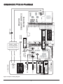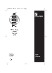
1
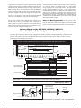
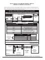
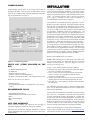
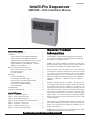
Intelli-Fin Sequencer
IFS-i&s-02
SMP3000 - 3014 Installation Manual
Table of Contents
General Product Information . . . . . . . . . . . . . . . . . . . . . . .1
Limitations . . . . . . . . . . . . . . . . . . . . . . . . . . . . . . . . . . . . .2
Options Offered on the SMP3000-SMP3002 . . . . . . .2
Options Offered on the SMP3003-SMP3005 . . . . . . .2
Options Offered on the SMP3002, 3005, 3014 and
SMP3014 (Boilers Only) Outdoor Air Reset . . . . . . .3
Options Offerered on the SMP3009 - 3012 and
SMP3014 - 4-20 mAReset . . . . . . . . . . . . . . . . . . . . .4
Parts List (Items Included in the Kit) . . . . . . . . . . . . . . . . .5
Items to be Provided by the Installer . . . . . . . . . . . . .5
Recommended Tools . . . . . . . . . . . . . . . . . . . . . . . . . .5
One Year Warranty . . . . . . . . . . . . . . . . . . . . . . . . . . .5
Installation . . . . . . . . . . . . . . . . . . . . . . . . . . . . . . . . . . . . .5
Location and Mounting . . . . . . . . . . . . . . . . . . . . . . . .6
Connecting to Electrical Supply . . . . . . . . . . . . . . . . .6
Sensor Location and Wiring Requirements . . . . . . . .7
E-Bus Communications Wiring . . . . . . . . . . . . . . . . .7
LonWorks® Termination Module . . . . . . . . . . . . . . . .8
System Integration . . . . . . . . . . . . . . . . . . . . . . . . . . .8
Troubleshooting . . . . . . . . . . . . . . . . . . . . . . . . . . . . . . . . .9
Sequencer Wiring Diagram . . . . . . . . . . . . . . . . . . . . . . . .10
Table of Figures
Figure 1 - Commissioning Label . . . . . . . . . . . . . . . . . . . .5
Figure 2 - Daisy Chain Connection . . . . . . . . . . . . . . . . . .6
Figure 3 - Rear E-Bus Connection . . . . . . . . . . . . . . . . . . .6
Figure 4 - Wire Termination for E-Bus Connection . . . . .6
Figure 5 - Sequencer - Rear View . . . . . . . . . . . . . . . . . . .6
Figure 6 - Sequencer - Inside View . . . . . . . . . . . . . . . . . .7
Figure 7 - Primary/Secondary Loop . . . . . . . . . . . . . . . . . .8
Figure 8 - Sequencer Wiring Diagram . . . . . . . . . . . . . . . .10
General Product
Information
The SMP3000 - 3005 Sequencing packages are an effective
way to improve efficiency, reduce maintenance, and enhance
the longevity of a hydronic system.
NOTE: This controller MUST be designed to operate with a
primary/secondary full flow boiler loop. This is due to the fact
that variable speed changes the operating characteristics.
Intelli-Fin boilers and water heaters give system designers
“conventional” sequencing options such as first on/last off and
first on/first off which are offered as part of this standard
sequencing package, however, the Intelli-Fin also provides a
whole host of optional sequencing packages on the SMP3003 SMP3005, SMP3009 - SMP3010 and the SMP3011 SMP3014.
Multiple sequencing options are available. The specific software programming required to sequence multiple boilers must
be specified at the time the appliances are ordered. The
sequencing options are used to control how multiple boilers or
water heaters are cycled to meet system demand. The sequencing options are programmed into an Excel 10 controller at the
factory based on the number of selectable sequencing algorithms ordered. The desired method of sequencing multiple
boilers or water heaters may be selected from the screen of the
Command Display.
There are up to five sequencing options that are selectable from
the Command Display, based on the sequencing package purchased. One sequencer has the capability of handling up to 16
boilers or water heaters.
NOTE: Separate sequencers must be used if desired to control
both boilers and water heaters simultaneously.
Save this manual for future reference.
Efficiency Optimized with Time Equalization – This is the
same as “Efficiency Optimized” but the lead/lag is based on
boiler or water heater run-times. The boilers or water heaters
will be sequenced to equalize run-times to within 24 hours over
a years time period. If no opportunity is given to cycle, the control will not interrupt action to equalize run-time.
WARNING:
Verify the correct
sequencing package is used for the
correct application.
LIMITATIONS
Efficiency Optimized Control Algorithm
Operation
These installation instructions are for sequencer kits SMP3000 SMP3014. These kits are for use with Intelli-Fin Models IB/IW
1500-2000 and can be used for the sequencing of up to 16 units.
The “efficiency optimized control algorithm” controls boilers to
achieve maximum operating efficiency by having boilers firing
at the lowest rate possible and still statisfying the load. Boiler
efficiency is highest at the lowest firing rate and lowest at the
maximum firing rate. At lower firing rates more heat is transferred from the combustion gases through the heat exchanger to
the water inside the boiler. The combustion gases are flowing
slower past the heat exchanger and give up more heat.
Model(s)
Boiler
IB 1500, 1700, & 2000
Water Heater IW 1500, 1700, & 2000
The efficiency algorithm works as follows: One firing rate is
commanded to all boilers. As soon as the firing rate to all boilers ON exceeds that required to bring on a new boiler at the minimum firing rate, a new boiler is ignited and begins firing. Once
the new boiler is operating and supplying heat, all boilers are
modulated down to a new minimum to compensate for the new
boiler being turned ON. A similar thing happens when a boiler
is subtracted from operation. When all boilers are firing at the
minimum and the load is decreasing, a boiler is shut OFF and
the remaining boilers ON are modulated up to satisfy the load
deficit.
Options Offered on the SMP3000 - SMP
3002 Standard Sequencing Packages
SMP3000 – Standard Sequencing Package for Water Heaters
SMP3001 – Standard Sequencing Package for Boilers
SMP3002 – Standard Sequencing Package for Boilers with
Outdoor Air Reset
First On – First Off – This is a lead/lag control functionality.
The sequencing of the boilers or water heaters is based on the
total loop load with added units being brought ON when the
units that are running are at 100% and the loop load is not being
met. Boilers or water heaters are turned OFF when the loop load
falls and the first boiler or water heater ON is at minimum load.
The “efficiency optimized control algorithm operation” can best
be illustrated with the following example:
Example: Assume we have a four boiler system, all boilers are
initially OFF and a load change occurs resulting in an overall
load of 20%. One boiler firing at maximum can satisfy only
25% of the load. The first boiler is ignited and modulates up to
a 50% firing rate. At this point a second boiler is ignited. One
boiler firing at 50% is equivalent to two boilers firing at 25%.
Both boilers modulate to 37.5% and the third boiler is ignited.
Two boilers firng at 37.5% is equivalent to three boilers firing at
25%. All three boilers now modulate to a firing rate of 27% satisfying the overall load of 20% at maximum efficiency with no
unnecessary cycling. Now assume the load changes to 15%. All
three boilers are modulated down to 25% and temperature is still
rising. One boiler is commanded OFF and the remaining two
boilers modulate up to 30% and satisfy the load.
First On – Last Off – This is a simple first on / last off without
rotation of the lead boiler or water heater.
Options Offered on the SMP3003 SMP3005 Custom Sequencing Packages
In addition to the sequencing options listed above in the
Standard Sequencing Packages, the Custom Sequencing
Packages offer the following sequencing enhancements:
SMP3003 – Custom Sequencing Package for Water Heaters
SMP3004 – Custom Sequencing Package for Boilers
SMP3005 – Custom Sequencing Package for Boilers with
Outdoor Air Reset
NOTE: This explanation has been idealized. In actuality, the
control algorithm assumes the switching firing rate is 33%. This
assumption prevents unnecessary cycling resulting from load
fluctuations that would be associated with a 25% switching firing rate.
Efficiency Optimized – The lead/lag will be based on first
on/first off lead/lag. The overall efficiency will be optimized to
run the boilers or water heaters at their highest efficiency.
Highest efficiency occurs at the minimum loading for each boiler or water heater. Therefore, this option will add boilers or
water heaters when the load reaches a point where the next boiler or water heater can run at minimum load.
Efficiency Not Optimized Control
Algorithm Operation
The “efficiency not optimized control algorithm” controls boilers to achieve the minimum number of boilers firing at one time.
Before a new boiler can be commanded ON, all the boilers cur2
rently ON are at a firing rate of 100% and the load is not being
satisfied. If the load can be satisfied with this new boiler modulating above the minimum, all the previously ON boilers are
held at a firing rate of 100% and the new boiler modulates up
and off, the boilers that are firing at the maximum are modulated back slightly so that the new boiler will modulate above
the minimum and not cycle. For the “efficiency not optimized” case, all boilers are at or near the maximum firing and
one boiler is modulating to satisfy the load fluctuations.
A better example would be to assume that we have a four boiler system, all boilers are initially OFF and a load change
occurs resulting in an overall load of 60%. The first boiler is
turned ON and modulates to 100%. The second boiler is
turned ON and the boiler is modulated to 100% and the load is
still not being satisfied. The third boiler is turned ON and
modulates to 40% satisfying the load. Now assume the overall load changes to 40%. The third boiler is turned OFF, the
second boiler is modulated down from 100% to 60% and the
first boiler remains at 100%.
The previous example used to illustrate how “efficiency optimized” works is not a good example for the “efficiency not
optimized” case. If it were applied to that example, only one
boiler would ever come ON. For an overall load of 20%, one
boiler would be ON and at a firing rate of 80% and for an overall load of 15% the firing rate would be 60%.
Notes for Both Approaches: In the previous examples, the boiler that would be turned OFF was based on first
on/last off for simplicity. Also in this explanation, the term
boiler was used, but the same holds true for a water heater.
Options Offered on the SMP3002, SMP3005, SMP3013,
and SMP3014 (Boilers Only) Outdoor Air Reset
Sequencer panels have the option of being equipped with Outdoor Air Reset, which automatically readjusts the temperature of the boiler loop to provide additional heat during cold days and provide for shutdown of the system on
warmer days when heating is not required.
W ater Temp . °F
INTELLI-FIN SEQUENCER OUTDOOR AIR RESET VALUES
SMP3002, SMP3005, SMP3013 & SMP3014 - BOILERS ONLY
Typical Values Shown
180°F
Max.
Reset Temp.
Calculated Setpoint
Setpoint Temp.
130°F
Shutdown
Outdoor Air Temp. °F
O.A. Min.
-10°F
O.A. Max.
Factory
Defaults
Item Description
Maximum Reset Temperature
Field Adjustable
Using Command
Display
70°F
Setpoint Temperature
Lockout
60°F
Special Factory/
Field
180°F
130°F
O.A. Minimum
-10°F
O.A. Maximum
60°F
O.A. Lockout
70°F
Factory Set (1)
NOTE:
4-20mA RESET HAS PRIORITY OVER OUTDOOR AIR RESET.
LBL2226 REVSequencer
Boiler Interface
Controller
+
+
+
+
+
+
+
+
Field Provided
Sensor Wiring
Polarity Insensitive
OA
SENSOR
3
2
2
1
1
Mounting
Bracket
Outdoor
Air Sensor
CONNECTIONS "SEE ACTUAL WIRING DIAGRAM FOR DETAILS" ON PAGE 10 OF THIS MANUAL.
3
Options Offered on the SMP3009, SMP3010, SMP3011,
SMP3012, and SMP3014 4-20mA Reset
Sequencer panels have the option of being equipped to handle a 4-20mA reset signal from a Building Management
System. When equipped as such, the sequencer has the ability to respond to variations in the 4-20mA signal by either
raising or lowering the water temperature or shutting down the units.
INTELLI-FIN SEQUENCER 4-20mA VALUES
SMP3009, SMP3010,SMP3011, SMP3012, SMP3013 & SMP3014
Not connected
or 0mA signal.
Typical Values Shown
ShutDown
Setpoint
Temp.
130°F
Off
130°F
0-3mA
3-5mA
6mA
Setpoint Temp.
180°F
Max. Reset.
Temp.
Calculated Setpoint
7 - 19mA
20mA
External 0mA to 20mA Signal
mA VALUE TO SEQUENCER
SEQUENCER ACTION TAKEN
0-3mA
USE SETPOINT
3-5mA
SHUTDOWN ALL UNITS
6mA
RUN AT SETPOINT
7-19mA
LINEARLY RUN BETWEEN
SETPOINT AND MAX. RESET TEMP
20mA
RUN AT MAXIMUM RESET TEMP.
Factory
Defaults
Item Description
Field Adjustable
Using Command
Display
NOTE:
Maximum Reset Temperature
Setpoint Temperature
SpecialField Values
180°F
130°F
4-20mA RESET HAS PRIORITY OVER OUTDOOR AIR RESET.
LBL2225 REVBoiler Interface
Controller
+
+
+
+
Negative Input (-) # 11 +
Positive Input (+) # 10 +
+
+
Sequencer
Black
+
Red
4-20mA Output
From BMS
Polarity
Sensitive
OPTIONAL
4-20ma INPUT
Com
0-20mA
Building
Management
System
CONNECTIONS "SEE ACTUAL WIRING DIAGRAM FOR DETAILS" ON PAGE 10 OF THIS MANUAL.
4
COMMISSIONING
INSTALLATION
Commissioning will be done at the factory and cannot be
changed in the field. Consult factory for more details. Please
reference the Commissioning Label for applicable serial numbers, as depicted below in Figure 1.
The sequencer is supplied in a separate control enclosure that
will be connected to multiple appliances via an E-bus connector on the rear of each appliance. The sequencer comes mounted in an enclosure that requires a field installed 120VAC power
source. An optional enclosure with a sub-base and 24VAC
power supply is available to allow remote mounting of a
Command Display adjacent to the sequencer.
Connection between multiple Intelli-Fin appliances is accomplished via an E-bus connection. An E-Bus terminal is provided on the rear of each appliance as depicted in Figures 2 and 3.
The minimum specification for the
communications wire is for
2
a Level IV, 22 AWG (0.034 mm ) plenum or non-plenum rated
(as applicable), unshielded, twisted pair, stranded wire. Use
plenum rated wire where required. See “Wire Requirements” in
your Intelli-Fin Installation and Service Manual for a listing of
manufacturers who supply communication wire meeting this
specification. The twisted pair wire is used to make daisy chain
connections (see Fig. 2) between the E-Bus terminals on multiple appliances. The E-Bus connection uses a Free Topology
Transceiver (FTT) to support a polarity-insensitive free topology wiring scheme for star, loop and/or bus wiring. The maximum number of nodes per segment is 60. The maximum number of nodes in a two-segment FTT network is 120, when using
a repeater between the two segments. Consult factory for additional information on interface wiring of multiple Intelli-Fin
appliances to an Energy Management System (EMS).
Wiring to the terminal blocks is as follows:
NOTE: When attaching two or more wires to the same terminal, twist wires together. Deviation from this rule can result in
improper electrical contact. (Reference Figure 4, when performing the following steps.)
Figure 1 Commissioning Label
PARTS LIST (ITEMS INCLUDED IN THE
KIT)
1. Strip ½ inch (13mm) insulation from the conductor.
2. Insert the wire in the required terminal location and tighten
the screw to complete the termination.
3. If two or more wires are being inserted into one terminal
location, twist the wires together a minimum of three
turns before inserting them.
4. Cut the twisted end of the wires to 3/16 inch (5mm) before
inserting them into the terminal and tightening the screw.
5. Pull each wire in all terminals to check for a good mechanical connection.
• (2) Remote Mounting Sensors
• (2) Bulbwells
• (Option) Outside Air Sensor
• (Option) Outside Air Mounting Bracket
• 22 AWG Communications Wire - 25ft. shipped with the unit
Items to be Provided by the Installer
• Mounting Screws
• 18 Gauge Shielded Cable (recommended for noisy environments)
For additional components used to interface multiple appliances, see the Intelli-Fin Installation and Service Manual provided with the appliances.
RECOMMENDED TOOLS
FTT networks are flexible and convenient to install and maintain. However, it is imperative to plan the network layout and
to create and maintain accurate documentation. Careful planning and up to date documentation facilitates compliance verification and future FTT network expansion. It also minimizes
unknown or inaccurate wire run lengths, node to node (device
to device) distances, node counts, total wire length, inaccurate
repeater locations, and misplaced or missing terminations.
• Small Flathead Screwdriver
• Medium Phillips and/or Flathead Screwdriver
• Pliers
• Wire Cutters/Strippers
• Drill
ONE YEAR WARRANTY
Factory warranty (shipped with sequencer) does not apply to
equipment improperly installed or improperly operated.
Note: A System Integrator’s Guide along with dedicated
resource files is located on our website at www.lochinvar.com,
select Boilers and then click on the Intelli-Fin picture.
Experience has shown that improper installation or system
design, rather than faulty equipment, is the cause of most operating problems.
5
Rear E-Bus Connection
Figure 2 Daisy
Chain Connection
run lengths, node to node distances, node counts, total wire
length, inaccurate repeater locations, and misplaced or missing
terminations.
Choose a location in a convenient interior or place where the
controls and connections are accessible and a 6” clearance can
be maintained above the sequencer. This clearance is needed to
allow access to the Neuron ID switch on the sequencer.
Mount the sequencer to the wall with four (4) mounting screws
(not supplied) through the mounting holes in the base as shown
below in Figure 5.
Figure 3 Rear E-Bus Connection
STRIP 1/2"
FROM WIRE
TO BE ATTACHED.
1/2" (13MM)
TWIST WIRES
TOGETHER WITH
PLIERS (MINIMUM
OF THREE TURNS)
INSERT TWISTED WIRES
UNDER TERRMINAL AND
TIGHTEN. CHECK FOR
A GOOD MECHANICAL
CONNECTION.
Figure 5 Sequencer - Rear View
Connecting to Electrical Supply
Figure 4 Wire Termination for E-Bus Connection
The sequencer contains one or more 120VAC to 24VAC step
down transformer(s); 24VAC is used to power the electronic components of the sequencer (Fig. 6). Supply a dedicated 120VAC input source to the transformer leads. The amp
draw of the sequencer is less than 15 amps.
Location and Mounting
It is recommended that the sequencer be mounted in close proximity to the units in order to avoid unknown or inaccurate wire
6
RLY2715 Inlet/Outlet Control
RLY2043
Interface Board
Commissioning
Label
Wiring
Diagram
E-Bus Communications Wiring
•Unswitched 24 V ac power wiring can be run in the same conduit as the E-Bus cable.
•All field wiring must conform to local codes and ordinances.
•Do not use different wire types or gauges on the same
LonWorks® network segment. The step change in line
impedance characteristics will cause unpredictable reflections
on the bus. When using different types is unavoidable, use a
router at the junction.
Transformer
Ground Terminal
Connection
4-20 mA Reset Label
(Optional)
Outdoor Air Reset Label
(Optional)
Figure 6 Sequencer - Inside View
Sensor Location and Wiring Requirements
Note: All wiring must comply with applicable codes and ordinances.
1. Disconnect external power before wiring to prevent electrical
shock or equipment damage.
2. The sequencer comes with two (2) remote mount sensors that
are shipped loose. These sensors should be installed in the
bulbwells that have also been shipped loose.
3. The bulbwells should be installed (1 each) in the supply and
return lines of the primary system piping.
a. The supply sensor should be located at least four (4)
pipe diameters downstream of the last connection from
this secondary piping loop to the primary loop (Fig. 7,
page 8).
b. The return sensor should be located at least four (4)
pipe diameters upstream of the first connection from
this secondary piping loop to the primary loop (Fig. 7,
page 8).
•The use of shielded cable for LonWorks® network wiring runs
is not recommended. The higher capacitance of the shielded
cable will cause degradation of communications throughput.
In noisy (high EMI) environments, avoid wire runs parallel to
noisy power cables or lines containing lighting dimmer
switches, and keep at least 3 inches (76mm) of separation
between noisy lines and the LonWorks® network cable.
However, in some cases where high electrical noise exists, the
use of shielded cable may be unavoidable. If it is felt that
shielded cable is necessary, consult the factory or a qualified
LonWorks® installer for direction.
•Make sure that neither of the LonWorks® network wires are
grounded.
•Communications wire connections are polarity insensitive.
Sensor wiring: 14 to 20 AWG (2.0 to 0.5 mm2) for runs >100 ft.
(30 m) twisted pair or shielded cable is recommended.
4. Wiring between the sensor and the sensor connector leads on
the sequencer should be as short as possible and be made with
18 gauge shielded cable (recommended but not required).
5. If the sequencer has been ordered with Outside Air Reset,
an outside air sensor and sensor mounting bracket will be
shipped with the sequencer.
6. Mount the bracket to an exterior wall with four (4) mounting
screws (not supplied) through the mounting holes in the
bracket.
7. Install the sensor into the mounting bracket.
8. Wiring between the sensor and the sensor connector leads on
the sequencer should be as short as possible and be made
with 18 gauge shielded cable. All wiring must comply
with applicable code and ordinances.
IMPORTANT: All field wiring must conform to local
codes and ordinances or as specified on installation
wiring diagrams!
7
Intelli-Fin
Sequencer
SYSTEM LOOP
Temp Sensor 10ft from first boiler
System
Pump(s)
12" max
or 4 pipe
diameters
Boiler #1
Boiler #2
Boiler Pumps on/off with
boiler(s)
Figure 7 Primary/Secondary Loop
LONWORKS® TERMINATION MODULE
1. One or two LonWorks® Network Termination Modules, part
number 209541B are required for a LonWorks® network
with FTT devices on it, depending on the configuration.
2. Double termination is required only when the network is a
daisy-chain configuration and the total wire length is greater
than 1640 ft. (500 m).
3. The maximum lengths described in Step 2 must be adhered
to for either a daisy-chain or free topology LonWorks® network layout.
System Integration
The intent of these wiring guidelines is to cover the connections
made to Lochinvar boilers. It is highly recommended that you
consult a qualified LonWorks® installer for integration of the
Lochinvar boilers into a LonWorks® based system.
8
TROUBLESHOOTING
SITUATION
Sequencer does not power up
Sequencer does not communicate
with boilers
POSSIBLE CAUSE(S)
CORRECTIVE ACTION
No 120VAC to transformer.
Check wiring to transformer from supply.
No 24VAC output from the transformer.
Replace transformer.
No continuity through the Run/Stop switch.
Turn the switch ON. Correct the wiring
at the switch or replace switch.
Faulty interface board(s).
Replace interface board(s).
Faulty sequencer.
Replace control.*
Faulty wiring between sequencer and boilers.
Correct wiring.
Building Energy Management System (EMS) Correct EMS.
has boilers locked out.
Temperature sensors reading
erratically
Bypass jumper not plugged into interface
board.
Replace jumper plug.
Outside air lockout engaged on units with
I/O reset.
Disconnect outside air sensor or wait until
outside air temperature drops below 70°F.
Poor wiring connections at sensors or
sequencers.
Correct wiring.
Sensor wiring routed with 120VAC
power lines.
Re-route sensor wiring.
Sensor located near electrical motors.
Move sensors.
Faulty interface board.
Replace interface board.
Faulty sequencer.
Replace control.*
Faulty sensor.
Replace sensor.
*Note: Replacement of the control will require domain, subnet and node addresses for all appliances in this network (appliance
will have to be recommissioned - consult factory). This must include all Intelli-Fin units and any Command Displays.
9
SEQUENCER WIRING DIAGRAM
Y
BL
8
9
LEFT SIDE WING BOARD
7
3
6
2
5
1
SEQUENCER
CONTROLLER
BIC V2.0.x
BK
RIGHT SIDE WING BOARD
5
4
3
2
1
COMMUNICATION CABLE
3
1
2
1
2
1
2
1
2
OA
SENSOR
1
2
OUTLET
SENSOR
G
BK
W
STOP/RUN
SWITCH
INLET
SENSOR
BK BK
ENABLE
SWITCH
R
OPTIONAL
GROUND
POS (+)
CHASSIS
GROUND
BL
Y
14
13
12
11
6
5
4
3
E-B US
A 1 - 6 22VDC
V/m a O U T
A1 - 5 G N D
V/ma
A 1 -1 G N D A 1 -2
OH M
OH M
4
9
D I- 1
1
8
G ND
2
7
D I- 2
3
A 1- 4
OH M
D I- 3
NEG (-)
GN D
OPTIONAL
A 1 -3
OH M
G ND
2
8
O UT
26
D I -4
1
16
7
OU T
2
7
1
17
6
OU T
E
GN D
24VAC
2
18
5
OU T
2
1
1
1
19
4
O UT
28
SEQUENCER
SCHEMATIC/WIRING
DIAGRAM
2
20
3
O UT
24
29
25
30
10
24VAC - 40VA
TRA NSFROMER
Inter nally Fused
INPUT
3
15
21
2
O UT
1
BK
R
OPTIONAL
4-20mA Reset
CONNECT TO
SEQUENCED
UNITS
NE
G
POS
OPTIONAL
RETURN
SUPPLY
OUTDOOR AIR
SENSOR
OUTLET
SENSOR
INLET
SENSOR
EXTERNAL
FIELD
CONNECTIONS
120 VAC
15 AMP
10
J ACK
J3
22
1
OU T
GND
LBL2139 REV C
Figure 8 Sequencer Wiring Diagram
E-B US
23
24
24
VAC
VAC
CO M
31
NOTES
11
12/03 - Printed in U.S.A.