1
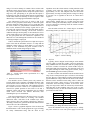
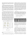
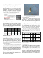
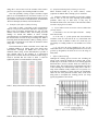
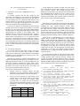
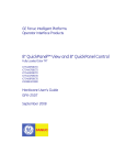
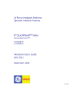
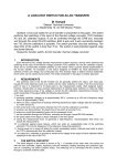
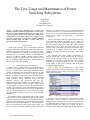
The Test, Usage and Maintenance of Power
Switching Subsystems
Kevin Paton
Teradyne, Inc.
North Reading MA
[email protected]
Abstract — Unlike signal switching, power switches have
significant minimum operational requirements for both voltage
and current. These minimum requirements affect usage in test
programs and self test approaches. This paper will discuss the
considerations necessary when testing power switches or when
using power switching in test programs. In addition, techniques
will be described which can reduce or remove build up of
deposits, improving switch operation.
I.
INTRODUCTION
Unlike signal switching, power switches have significant
minimum operational requirements for both voltage and current
minimum requirements affect usage in test programs (TPSs)
and self test approaches. In addition to TPS usage and testing
considerations, power switches must also be maintained since
they have a tendency to build up deposits on their contacts
which can degrade the characteristics of the switch. However,
there are techniques which can reduce or remove build up of
deposits, improving switch operation.
II.
POWER SWITCHING SPECIFICATIONS
When creating a system self test or laying out the paths to
be used in a test program, the test engineer needs to consider
the types of signals or power that will pass through the various
switches to determine if the switch specifications line up with
the actual requirements of the self test or the test program.
When reviewing switch specifications the usual ratings that one
would investigate include capabilities such as maximum
power, maximum voltage, maximum current and path
resistance. However, one specification that often goes
unnoticed is the minimum contact rating. From Wikipidea “The
minimum contact rating is based on what is known as the
“wetting current” (or sealing current) is the minimum current
needing to flow through a newly-closed mechanical switch or
relay in order to break through any film (contact oxidation) that
may have been deposited on the switch contacts while open.
The film (contact oxidation) occurs often in areas with high
humidity” [1]
The reason this rating is important is that any time a signal,
either complex or DC, is transmitted through a switch and that
signal has current and / or voltage levels less than the switch’s
minimum contact ratings it can lead to unreliable operation (the
reasons for this will be described below). Yet many engineers
do not even consider this rating. Some switch vendors even
leave this rating off of their published switch specifications
978-1-4244-9363-0/11/$26.00 ©2011 IEEE
however, it is critical that the test or TPS designer obtain this
specification because it is an important factor in the design of
the test. If it is not in the standard published datasheet then the
switch vendor should be approached to supply this
specification.
One key characteristic that affects these ratings is the relay
contact material. Switches that handle up to 3 Amps will
typically have some form of gold plating on their contacts. If is
the switch supports between 3 Amps and 5 Amps, the gold
plating tends to be an option but above 5 Amps the switch
contacts will be constructed of some other more robust metal,
such as silver or tungsten, which is not quite as good a
conductor as gold but can tolerate the higher currents being
switched.
The following three tables contain specifications for
different switch types, which illustrate how the minimum
contact rating can vary based on the current carrying
capabilities of the relays involved. These tables contain
specifications for signal switching with very low minimum
contact ratings to high power switching with much higher
current and voltage minimums.
Table 1 shows the specifications for a signal switch
module. Note that the maximum current value is only 2 amps
and the minimum contact rating of the signal switch is very
small at 10mV and 10uA.
Table 1 - Vendor signal switch specification sheet
The next “level” of switches are low power switches, which
operate from 3 amps to 5 amps. It is important to note that
although switches with these specifications are sometimes used
for signal transmission, doing so uses the switch outside of its
specified operating area. This type of switch will have a
minimum contact rating that is higher than the signal switch, a
rating of 5V and 10 mAmps is common. These switches with
maximum current values between 3 amps and 5 amps may or
may not have gold plated contacts. Relays that operate in this
range may offer gold plating as an option but this option is
transparent to the end user and is dictated by the switch module
vendor which adds some difficulty for the test engineer when
determining if a cleaning approach should be employed.
One characteristic of this type of switch is that if the
contacts are not gold plated, their ability to deal with signals
below the minimum contact rating is not very good. But when
the switch contacts are gold plated the switch transmission of
these “below minimum contact ratings” signals can be quite
successful. The reason for this is that the gold plated contacts,
if not abused with hot switching, will be more resilient to
oxidation build ups and the quality of the transmission of low
power signals will be more consistent over time. If the contacts
are not gold plated then the transmission capabilities can
deteriorate over time although this situation can be remedied if
a cleaning technique is employed.
impedance across the switch contacts. On this particular switch
A-fritting occurs when the signal across the contacts hits
approximately 330 mV and completes when the current hits
approximately 0.4 amps at which point the voltage level drops
to a steady 0.18 V regardless of the level of current that is
supplied.
This graph also depicts the affect that the fritting has on the
path resistance. Initially there are 1.5 ohms across the switch
but after A-fritting this immediately drops to around 0.5 ohms.
As more current flows, B-fritting causes the contact resistance
to drop even further.
Note the initial resistance of 1.5 ohms drops to 19 mOhms
after fritting (From Tyco Automotive app note)
Table 2 contains the specifications for a high current power
switch. Note that the maximum current is 16 amps and the
minimum contact ratings are much higher at 12V and 100
mAmps. It is not uncommon for power switches to have a
minimum contact current rating as high as 1Amp.
Figure 1 - Affect of fritting
B. Self Test
Typically, when a designer starts looking at switch module
self tests within a system they produce a layout in which they
bring a DMM to the receiver interface and use a jumper pattern
across the switches to measure the switch module relays for
both opened and closed resistances. This approach works well
for signal switching but when testing power switches, using a
standard DMM approach can lead to problems.
Table 2 - Vendor signal switch specification for a high
current power switch
A. Minimum Contact Rating
The materials used to construct power relay contacts are
typically metals such as tungsten or palladium and alloys such
as silver/nickel. These metals tend to oxidize in a very short
period of time even in a sealed relay. This oxidation increases
the resistance across the contacts so it is important that it is
removed for optimal operation of the switch. To do this a
minimum voltage and current combination must be applied
which causes electrical and thermal destruction, thus
eliminating the layer of contaminants.
This electrical destruction is in the form of an arc or a spark
at lower voltage and is known as “A-fritting”. The electrical
destruction forms a thin hole in the oxidation layer which
allows current to flow. The resulting current flow is known as
“B-fritting” and this flow generates the thermal destruction that
removes the rest of the contaminants.
Figure 1 shows a graphical depiction of the electrical and
thermal destructive effect. In this graph the two types of fritting
are clearly demonstrated along with the affect on the
As shown in Table 2 the minimum current needed to ensure
relay closure on that particular power switch was 100 mAmps
and 12V. However, when making resistance measurements the
typical DMM uses voltages and currents that are much smaller
than the switch’s minimum contact rating. Table 3 shows the
current and voltage values used by several popular COTs
instruments when measuring resistance at the lowest meter
range, the range used to make the closed relay measurements.
Note that none of these modules come close to the 12 volts,
100 mAmps necessary to meet the minimum contact resistance
specification for this switch.
Meter
Current
Voltage
Teradyne Ai760
1mA
100 mV
Agilent 1412
1mA
100 mV
Agilent 3458
10mA
100 mV
Teradyne Ai710
100mA
500 mV
Table 3 – Current and Voltage Levels Used by Various DMMs
When Making Low Range Resistance Measurements
Given this information the only practical way to reliably
test power switches is to use a DC power supply to source the
required voltage and current levels. Most testers offer some
form of off the shelf DC power supply that provides internal
voltage and current read-back capabilities, required by this self
test approach.
In the test configuration illustrated in Figure 2 a DC power
supply with internal measurement capabilities is connected in a
configuration which allows testing of 5 individual switch
modules. A load resistor is placed across the DC power supply
allowing the power supply to be tested before any relay
verification is done. In the design, a precision (0.5%) 100 ohm,
25 watt load is chosen to allow the best combination of voltage
and current verification of the supply. The supply used is a
35V, 8.5 amp supply so the full voltage of the supply (35V)
can be verified and the current can be tested to approximately
350 mAmps. If the power supply test fails then no switch tests
are run.
An important aspect of having the 100 ohm load across the
DC power supply is that it provides the means to factor out the
error in the power supply measurement circuitry. This test
approach uses the DC power supply to measure the current
passing through the relay test paths but on many power
supplies the amount of specified error can be significant
enough so that using a DC power supply is impractical, in
some cases reaching 80% error. To overcome this problem an
initial measurement is made by setting the DC power supply to
the test voltage that will be used in the relay test which in this
case is 12 volts. In an ideal set up this would result in 120
mAmps across the 100 ohm load. By using the same test
voltage and highly accurate load resistors, the resulting current
measurement across the 100 ohm load will provide an offset to
be used for all relay path measurements. For example, if the
calculated expected value is 120 mAmps but the initial test
result is 100 mAmps, adding 20 mAmps to all relay test result
calculations will factor out the power supply and load error.
configuration is robust however, if a path is stuck closed, an
alternate means must be used to determine which switch
module is faulty. To help isolate this type of failure down to the
module level different load resistors are used for each module
under test. If there is a stuck closed path the module will be
indicted based on the calculated path resistance. This would be
caught during the initial test when the power supply is tested
standalone across the 100 ohm load. If a switch path is shorted
the load associated with that module would then be in parallel
with the power supply’s 100 ohm test load and the resulting
current allows the test program to mathematically determine
the faulty module. Because of the possibility of a shorted path
it is important that a reasonable current limit value is chosen
during this initial test to eliminate the possibility of damage to
the test circuitry or the module under test.
C. Test Limits
When calculating the test limits, the first step is to
determine the expected current through a perfect path. Table 4
contains values particular to the first module in Figure 2, which
has a 25 ohm load attached resulting in an expected current of
0.60 amps (12V/(100Ω||25Ω)). If the maximum relay path
resistance to be allowed is 3 ohms the low limit would be:
•
Test Limit = Vin / (((R_PS_load || R_module_load) *
(1+R _load_error)) + R_test_limit)
•
Test Limit = 12v / ((20 Ω *1.01) + 2 Ω)
•
Test Limit = 541 mAmps
Calculations for Relay Testing
Vin
PS
Load
12V
100Ω
R2
25
Ω
R1//R2
Curr
R1
Curr
R2
Curr
Total
Power
R1
Power
R2
20 Ω
120
mA
480
mA
600
mA
1.44W
5.76W
Table 4 - Key Voltages and Currents in the Test Circuit
On the high limit side the only factor which should allow the
measured current to go above the 0.60 amp expected current
would be an error in the 25 ohm module test load and since all
other sources of error would have been factored out in the
initial current test. This would occur if the 25 ohms load was
less than 25 ohms. Using a 1 Ω limit would produce an upper
value of 619 mAmps.
•
Figure 2 - Self Test Layout using Single DC PS to Test 5
Modules
The test configuration in Figure 2 allows the 20 switches
per module to be tested by one power supply. This
Test Limit = 12v / (100 ||(25 Ω - 1 Ω)) = 619 mAmps
D. Relay Cleaning
In the power relay specifications section, the effect that
“fritting” has on clearing the relays of contamination was
discussed. In some situations the buildup of contaminants on
power relays can become significant enough that a method is
required to rectify the problem. To deal with this issue relay
vendors recommend periodic cleaning through the use of
arcing. From a Tyco application note: “Controlled arcing of
short duration can be beneficial in achieving the rated life of
the contacts”.
Unlike fritting, in which minimum levels of voltage and
current are applied to a closed relay, arcing is achieved through
hot switching of the relays with higher levels of voltage and
current applied. The appropriate voltage and current levels are
based on the type of material used in the relay contacts.
The first step in designing an approach to generate a
cleaning arc is to determine the metals that make up the relay
contacts so that the specific levels of voltage and current
necessary to develop an arc can be defined. It may require
contacting the switch vendor for a relay datasheet if the
information is not available in the switch module user’s
manual. It may also be possible to track down the appropriate
relay data sheet by getting the relay part number off of the relay
as shown in Figure 3, an actual switch module relay photo.
Figure 4 - Relay cleaning setup
Figure 3 – Spec sheet showing relay contact material
Once the contact material is known, Table 5 can be
referenced to determine the arcing voltage and current
necessary for the relay to be cleaned. For example, the contact
material of the relay in Figure 3 consists of a combination of
silver and nickel. Based on the material with the higher values,
in this case nickel, by selecting a voltage of 14V and a current
of 0.5 amps, an arc will be generated.
Material
Electrical
Conductivity
Melt
Voltage
Arc
Voltage
Arc
Current
Gold
77
0.43
15
0.38
Nickel
25
0.65
14
0.5
Palladium
16
0.57
15
0.5
Silver
105
0.37
12
0.4
Tungsten
31
0.75
15
1.0
Table 5 - Relay arcing voltage and current values (From Tyco
app “Relay Contact Life” [3])
Knowing the arc voltage and current, a load must be chosen
which will produce the required arc current when the power
supply is programmed to output the arc voltage. In this case
using a 28 ohm load would produce the exact current of 0.5
amps desired when the power supply is set to 14V. Since these
values do not have to be exact, opting for a more common 25
ohm, 25 watt load resistor is a good option. This will provide a
current of 560 mAmps from the power supply and is sufficient
for this cleaning approach.
The cleaning approach itself can be an automated program
with a formal fixture or, if the need for cleaning is infrequent, a
manual set up can be built using the switch module’s soft front
panel to manually control the switches. The photo in Figure 4 is
an actual set up used to manually clean switch modules. In this
case power is brought from an onboard DC power supply to the
switch interface via jumpers that contain the required load. A
daisy chain of jumpers is placed across the switches with the
high lead on one side of the relay string and the low lead on the
other. Since there is no requirement to test the relays it is not
necessary to isolate the individual relays, which makes a daisy
chain approach the preferred method.
E. Automated Example
Figure 2 shows the schematic used for the self test but now
the setup will be used to clean the five individual switch
modules. Table 6 shows the load resistors used and the power
and current calculations. Note that the voltage is kept at a
minimum of 14V and the current at 0.5 amps or greater to meet
the arcing level requirements derived from Table 6.
This design example would be overly complicated if it was
not a dual purpose approach. If this was to be used only for
relay cleaning the design could be simplified. All load resistors
with the exception of the 25 ohm load could be eliminated and
the switches ganged together to accomplish a cleaning circuit.
Note that in the previous Self Test section all the self tests
are run at lower voltages while, for the relay cleaning, the
voltages are increased. This keeps the arcing limited to the
cleaning procedure only.
Calculations for Cleaning Currents and Voltages
Vin
14V
PS
Load
100 Ω
Rsw
25 Ω
Rld//
Rsw
20 Ω
15V
100 Ω
30 Ω
23 Ω
18V
100 Ω
35 Ω
26 Ω
23V
100 Ω
45 Ω
31 Ω
25V
100 Ω
50 Ω
33 Ω
I
Rld
140
mA
150
mA
180
mA
230
mA
250
mA
I
Rsw
560
mA
500
mA
514
mA
511
mA
500
mA
I
Total
700
mA
650
mA
694
mA
741
mA
750
mA
Power
Rsw
7.8 W
Power
T
9.8 W
7.5 W
9.75
W
12.5
W
17 W
9.3 W
11.75
W
12.5
W
18.75
W
Table 6 - Calculations for the first two modules being tested
using layout in Figure 2
F. Gold Plated Relays
When considering cleaning power switches, it is important
to know that if the switch handles 5A or less there is a chance
that the relay contacts are gold plated. A gold plated contact
resists oxidation and is a superior conductor. Because of this,
switches using gold plated relays tend to work well below the
minimum contact rating allowing even TTL signals to pass. If
the contacts are gold, using the arcing process could cause the
gold plating to burn off of the contacts resulting in degraded
operation at levels below the relay’s minimum contact rating. If
the switching will be used at levels over the minimum contact
rating, this is not an issue but if the switches will be used to
pass lower level signals, hot switching should be avoided.
Note: The possibility of using 5A power switches as signal
paths is not recommended but is raised here because it is not
uncommon to see this in real world applications. This approach
has potential issues which, are discussed in the section entitled
“Real Life Examples, Problems, and Considerations”.
G. Examples of the Affects of Relay Cleaning
The results in Table 7 and Table 8 show measurements
made on a 5A power switch before and after a cleaning cycle.
Most of the pre-cleaning measurements are well over 500
mOhms with one at almost 3 ohms. After cleaning, all of the
readings are around 500 mOhms or better. Through
experimentation it was found that after a couple hundred cycles
the measurements were back to the pre-cleaning state. What is
interesting about this demonstration is that by cleaning, the user
could make measurements well under the minimum contact
rating value … for a while.
The measurements in Table 7 and Table 8 were made with
a standard DMM so no fritting takes place during these
measurements. Although the DMM does not meet the
minimum contact rating, for this demonstration it provides a
more tangible affect of the cleaning. If a measurement
approach was used that did meet the minimum contact rating, it
could be assumed that the results in Table 7 would be
significantly better but would mask the cleaning affect.
H. Symptoms Indicating Relay Cleaning is Necessary
When oxidation builds up on switch contacts, various
symptoms can indicate that a cleaning cycle is warranted.
1) Failures in TPSs start appearing on previously working
TPSs or there are self test errors reporting path continuity
problems. These may be hard errors or they may be
intermittent failures since each closure of the affected switches
can make varying level of contact.
2) If you connect a meter across the various switches then
you may observe:
a) Resistances over the rated path resistance – usually
more than an ohm.
b) If the relay is cycled opened and closed different
resistance values are seen and can be very inconsistent with
variations of 100s of mOhms to ohms. On a clean relay you
will usually see reading within 10 or 20 mOhms on a switch
cycle.
c) If you leave the meter attached you may see the
readout drift lower over time although the drift can reverse and
go back up. Regardless, the drift can be over the range of
many ohms.
I. Effects of Hot Switching
Although the cleaning process involves hot switching the
effects on the switch life should not be adverse and, in fact,
should help to extend the switch life. The cleaning approach
described above involves currents which are relatively low,
around ½ amps. The graph in Figure 10 demonstrates the effect
of hot switching on a common relay family that is used on 5
Amp switch modules readily available for test systems. It is
clear that hot switching at certain currents can significantly
reduce the life of the particular switches while, at the levels
being used to accomplish the cleaning process (0.5 amps
typical), degradation is not a factor.
Table 7 - Relay measurement results before cleaning routine
Figure 5 - Effect of hot switching on relay life
Table 8 - Relay measurement results after cleaning routine
III.
REAL LIFE EXAMPLES, PROBLEMS, AND
CONSIDERATIONS
A. TPS Failure Leads to More DMM Induced Failure
Symptoms
A customer reported that his TPS would not run
consistently. He stated that he could connect up his handheld
meter across the switching being used by the TPS and see
elevated readings that were inconsistent and tended to float
around, therefore he suspected the connections to his power
relays were the cause. He re-terminated several of the receiver
pins involved and this did not changed the results.
A field service engineer was dispatched to investigate and
used the system self test to diagnose the problem. It was found
that there were two faulty pins at the switch module interface
and that the pins the TPS designer had flagged with his manual
measurements were actually in good working order. The
handheld meter the designer had used delivered 1 mAmp at
100 mV to measure a power switch that had a minimum
contact rating of 500 mAmps at 12 V. To effectively trouble
shoot these switch paths the customer would have needed a
power source with a load in series that would create ½ amp of
current required by the switch he was measuring. With this set
up the hand held meter could be used in the DC voltage mode
to take a voltage measurement that could be used to calculate
the resistance.
B. Intermittent TPS Results
It is not uncommon to find power switches, particularly
lower level 5A power switches, used as paths for various
signals and for connections to make resistance measurements
in addition to their intended purpose of passing power. This
practice is highly discouraged.
Related to this situation, a customer reported that their test
program, which had operated effectively for months, was now
displaying intermittent results. It was determined that the test
used power switches to transmit TTL signals. Table 9 shows
the voltage and current levels for TTL signals and one can see
that many of the logic levels do not have the voltage and
current levels needed for fritting to take place.
Some factors could cause this type of failure.
• Deposits caused by oxidation increase the path
impedances over time potentially causing a program
that worked reliably initially to become intermittent.
•
The power switch possibly has gold plating on the
contacts which, if used in other TPSs to pass higher
currents and/or were being hot switched, could
eventually burn off, causing the path transmission
characteristics to significantly degrade over time to the
point that the paths can no longer support TTL signal
transmission
Logic State
Output
Input
In this situation, the engineer can either rewire the fixture
and rewrite the TPS to use signal switching or use a regular
relay “cleaning” regimen. The cleaning techniques were
described in the previous section with the end result being that
the contaminants that can build up on relay’s contacts can be
removed allowing the switch to work at levels below the
minimum contact rating. This customer opted to rewire their
fixture which was the recommended approach.
IV.
When testing or troubleshooting power switch paths the
engineer has to consider the limitations of using standard
DMMs to make path resistance measurements. Using a DMM
will provide some basic information but only readings that
indicate a total closed path (shorted) or an open can be trusted.
Readings that vary from 1 ohm to 100 ohms could be caused
by oxidation on the relays not overcome by the current and
voltage from the meter. The best approach for testing power
switch paths is to use DC power supplies which provide the
minimum levels of voltage and current required to ensure a
solid relay closure.
To get the longest possible life from power switches and to
obtain consistent test results over a long period of time, a relay
cleaning program along with the necessary fixturing and
software are needed. Cleaning should be done at intervals
which are dictated by the test system’s usage and the cleaning
approach should be adjusted based on feedback from system
users regarding any TPS or self test intermittencies.
V.
[1]
[2]
[3]
[4]
[5]
[6]
[7]
Voltage High
2.4 V
2.0 V
Voltage Low
0.4V
0.8 V
[8]
[9]
Current High
400 uA
40 uA
Current Low
16 mA
1.6 mA
Table 9 - Power and current levels for TTL signals
CONCLUSION
When laying out test programs or self tests the test engineer
needs to take into account all switch module specifications
including the often ignored minimum contact rating
specification to ensure that the best available paths are used for
the signal and power routing. Using power paths for signal
transmissions should absolutely be avoided. A TPS using this
approach may appear to work during the initial development
cycle it could very well fail weeks or months down the road
displaying intermittent failures which are difficult to diagnose.
REFERENCES
Wikipedia,
Definition
of
Relay
Wetting
Current,
http://en.wikipedia.org/wiki/Wetting_current
VTI Corporation, SMP3001, SMP5005 and SMP2001 Specification
Sheet, SMP2 Series User’s Manual, July 2004,
Tyco
Electronics
Corporation,
Relay
Contact
Life,
http://relays.tycoelectronics.com/appnotes/app_pdfs/13c3236.pdf
Tyco Electronics Corporation, Power Switching Applications for High
Voltage Relays, Graph showing hot switching effects ,
http://relays.tycoelectronics.com/kilovac/power/
Porter Brumfield Spec sheet link - RT Series Potter Brumfield Relay
Specification http://relays.tycoelectronics.com/pnb.asp (click on RT DC
Coil – 8-16A, One or Two Poles)
Omron Corp, 5A Slim socket mountable PCB Relay–
http://www.components.omron.com/components/web/webfiles.nsf$FILE
S/family.html?ID=TABE-72ZR5S
Tyco T90 relay spec sheet - http://relays.tycoelectronics.com/pnb.asp
(click on T90 - 30A, 1 Pole, DC Coil PCB Relay)
Agilent
3458A
DMM
data
sheet
http://cp.literature.agilent.com/litweb/pdf/5965-4971E.pdf
Agilent
1412
DMM
data
sheet
http://cp.literature.agilent.com/litweb/pdf/5965-5563E.pdf