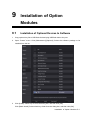
1
TE7 Diagnostic Ultrasound System Service Manual (Advanced) Revision 5.0 Table of Contents Table of Contents................................................................................................................. i Version Information ............................................................................................................. I Intellectual Property Statement ......................................................................................... II Applicability ........................................................................................................................ II Responsibility of Mindray .................................................................................................. II Warranty Statements: ...................................................................................................... III Customer Service Department .......................................................................................... IV Descriptions Committed ................................................................................................... IV 1 Safety Precautions.................................................................................................... 1-1 1.1 1.2 Meaning of Signal Words................................................................................................. 1-1 Symbols .......................................................................................................................... 1-1 1.2.1 Meaning of Safety Symbols ...................................................................................... 1-1 1.2.2 Warning Labels ........................................................................................................ 1-2 1.2.3 General Symbols ..................................................................................................... 1-2 1.3 Safety Precautions .......................................................................................................... 1-4 1.3.1 Electric Safety .......................................................................................................... 1-4 1.3.2 Mechanical Safety.................................................................................................... 1-5 1.3.3 Personnel Safety...................................................................................................... 1-5 1.3.4 Others...................................................................................................................... 1-6 2 Product Specifications ............................................................................................. 2-1 2.1 Introduction ..................................................................................................................... 2-1 2.1.1 Intended Use ........................................................................................................... 2-1 2.1.2 System Appearance ................................................................................................. 2-1 2.1.3 Trolley Appearance .................................................................................................. 2-3 2.1.4 Peripherals Supported ............................................................................................. 2-5 2.2 Specifications .................................................................................................................. 2-6 2.2.1 External Dimensions and Weight .............................................................................. 2-6 2.2.2 Electric Specifications .............................................................................................. 2-6 2.2.3 Environment Specifications ...................................................................................... 2-6 2.2.4 Monitor Specifications .............................................................................................. 2-7 3 System Installation ................................................................................................... 3-1 3.1 Installation Preparations .................................................................................................. 3-1 3.1.1 Electrical Requirements ........................................................................................... 3-1 3.1.2 Installation Condition ................................................................................................ 3-2 3.1.3 Installation Confirmation ........................................................................................... 3-2 3.2 Unpacking ....................................................................................................................... 3-3 3.2.1 Unpacking Process .................................................................................................. 3-3 3.2.2 Check ...................................................................................................................... 3-8 3.3 Installation of Whole Device............................................................................................. 3-8 3.3.1 Connecting Power Cable.......................................................................................... 3-8 3.3.2 Connecting a Ultrasound Probe................................................................................ 3-8 3.4 Installing Peripherals ....................................................................................................... 3-9 3.4.1 Connecting the Footswitch ....................................................................................... 3-9 i 3.4.2 Connecting/Removing a USB Devices..................................................................... 3-11 3.4.3 Graph/Text Printer .................................................................................................. 3-12 3.4.4 Video Printer .......................................................................................................... 3-14 3.4.5 Barcode Reader ..................................................................................................... 3-14 3.5 System Configuration .................................................................................................... 3-17 3.5.1 Power-on Running ................................................................................................. 3-17 3.5.2 Enter Doppler......................................................................................................... 3-17 3.5.3 System Preset ....................................................................................................... 3-19 3.5.4 Peripheral Preset ................................................................................................... 3-21 3.5.5 Network Preset ...................................................................................................... 3-23 3.5.6 DICOM/HLP Preset ................................................................................................ 3-25 3.5.7 System Information Verification .............................................................................. 3-30 4 Product Principle ...................................................................................................... 4-1 4.1 Function Structure of Hardware System ........................................................................... 4-1 4.1.1 Probe Socket ........................................................................................................... 4-1 4.1.2 Front-end Circuit ...................................................................................................... 4-1 4.1.3 Ultrasonic Engine ..................................................................................................... 4-2 4.1.4 Back-end Platform.................................................................................................... 4-2 4.1.5 Person-and-machine Communication ....................................................................... 4-2 4.1.6 Power Supply & Battery ........................................................................................... 4-3 4.2 Physical Structure of Hardware System ........................................................................... 4-4 4.2.1 Physical Structure and Connection of Hardware System........................................... 4-4 4.2.2 Circuit Principle of Hardware System........................................................................ 4-5 4.2.3 Hardware Board ....................................................................................................... 4-6 4.2.4 Hardware Module..................................................................................................... 4-7 4.2.5 The Description on Hardware System ...................................................................... 4-9 5 Checking Performance and Functions .................................................................... 5-1 5.1 5.2 Description ...................................................................................................................... 5-1 Checking System Status .................................................................................................. 5-1 5.2.1 Running Status......................................................................................................... 5-1 5.2.2 Working Condition .................................................................................................... 5-1 5.3 General Check ................................................................................................................ 5-2 5.3.1 Check Flow .............................................................................................................. 5-2 5.3.2 Check Content ......................................................................................................... 5-2 5.4 Functions Checking ......................................................................................................... 5-4 5.4.1 Checking Flow ......................................................................................................... 5-4 5.4.2 Checking Content .................................................................................................... 5-4 5.5 Performance Test .......................................................................................................... 5-18 5.5.1 Test Procedures ..................................................................................................... 5-18 5.5.2 Test Content........................................................................................................... 5-18 6 Software Installation & Maintenance ....................................................................... 6-1 6.1 6.2 6.3 6.4 Enter Maintenance .......................................................................................................... 6-1 Software Installation/Restoration ..................................................................................... 6-2 Enter Windows ................................................................................................................ 6-2 Software Maintenance ..................................................................................................... 6-3 6.4.1 Log Export ............................................................................................................... 6-3 6.5 Data Backup and Storage ................................................................................................ 6-3 6.5.1 Preset Data Management......................................................................................... 6-3 6.5.2 Patient Data Backup and Restoration ....................................................................... 6-5 ii 6.6 7 Field Replaceable Unit .............................................................................................. 7-1 7.1 7.2 8 Introduction on HDD Partition Data .................................................................................. 6-5 Main Unit ......................................................................................................................... 7-1 Mobile Trolley .................................................................................................................. 7-6 Structure and Assembly/Disassembly .................................................................... 8-1 8.1 Structure of the Entire System ......................................................................................... 8-1 8.1.1 Main Unit ................................................................................................................. 8-1 8.1.2 Mobile Trolley........................................................................................................... 8-2 8.2 Main Unit Assembly/Disassembly .................................................................................... 8-4 8.2.1 Preparation .............................................................................................................. 8-4 8.2.2 Dust-proof Mesh ...................................................................................................... 8-5 8.2.3 Battery ..................................................................................................................... 8-5 8.2.4 Back Cover Assembly of Main Unit ........................................................................... 8-6 8.2.5 Front Cover Assembly of Main Unit .......................................................................... 8-8 8.2.6 Probe Board Assembly............................................................................................. 8-9 8.2.7 SSD and Wireless Adapter ..................................................................................... 8-10 8.2.8 Main Board Assembly ............................................................................................ 8-12 8.2.9 ECG module .......................................................................................................... 8-14 8.3 Trolley Assembly/Disassembly....................................................................................... 8-14 8.3.1 Preparation ............................................................................................................ 8-14 8.3.2 Wet Tissue Holder .................................................................................................. 8-15 8.3.3 Printer .................................................................................................................... 8-16 8.3.4 Upper Cover of Trolley’s Handle ............................................................................. 8-17 8.3.5 Main Unit Support .................................................................................................. 8-18 8.3.6 Support .................................................................................................................. 8-19 8.3.7 Front/Back Cover of the Stand................................................................................ 8-20 8.3.8 Lower Cover Assembly of Trolley’s Handle ............................................................. 8-22 8.3.9 Upper Cover of the Base ........................................................................................ 8-24 8.3.10 Cable Reel Assembly ............................................................................................. 8-25 8.3.11 Stand Assembly ..................................................................................................... 8-27 8.3.12 Caster .................................................................................................................... 8-31 9 Installation of Option Modules ................................................................................. 9-1 9.1 9.2 Installation of Optional Devices to Software ..................................................................... 9-1 Installation of the Accessory Kits and Optional Devices to Hardware ................................ 9-3 9.2.1 Storage Tray ............................................................................................................ 9-3 9.2.2 Probe Holder to the Trolley ....................................................................................... 9-4 9.2.3 Probe Holder............................................................................................................ 9-4 9.2.4 Desktop ................................................................................................................... 9-4 9.2.5 VESA Connecting Rod ............................................................................................. 9-5 10 System Diagnosis and Support ............................................................................. 10-1 10.1 General Status Indicator ................................................................................................ 10-1 10.1.1 Display Status Indicator .......................................................................................... 10-1 10.1.2 Status of Whole Machine........................................................................................ 10-1 10.2 Get Whole Machine Started ........................................................................................... 10-3 10.2.1 Power-on Process of Whole Machine Supplied by AC ............................................ 10-4 10.2.2 The Start-up Process of BIOS ................................................................................ 10-4 10.2.3 Windows Start-up ................................................................................................... 10-4 10.2.4 The Start-up of Doppler .......................................................................................... 10-5 10.3 Alarming and Abnormal Information ............................................................................... 10-8 iii 10.3.1 Power Error............................................................................................................ 10-8 10.3.2 Abnormal Voltage of System Power ....................................................................... 10-9 10.3.3 Abnormal Temperature ......................................................................................... 10-10 10.3.4 Fan Error ............................................................................................................. 10-10 10.3.5 PHV Error ............................................................................................................. 10-11 10.3.6 Other Errors ......................................................................................................... 10-12 10.4 Self-test ....................................................................................................................... 10-12 10.4.1 Self-test Introduction ............................................................................................ 10-12 10.4.2 Operation Procedure of Maintenance Self-test ..................................................... 10-12 10.4.3 User Self-test ....................................................................................................... 10-18 10.4.4 Test Report .......................................................................................................... 10-19 11 Care and Maintenance ............................................................................................ 11-1 11.1 Overview ........................................................................................................................ 11-1 11.1.1 Tools, Measurement Devices and Consumables...................................................... 11-1 11.1.2 Routine Maintenance Items ..................................................................................... 11-2 11.2 Cleaning......................................................................................................................... 11-3 11.2.1 System Cleaning ..................................................................................................... 11-3 11.2.2 Peripherals Cleaning ............................................................................................... 11-5 11.3 Check............................................................................................................................. 11-5 11.3.1 General Check ........................................................................................................ 11-5 11.3.2 System Function Check .......................................................................................... 11-6 11.3.3 Check for Peripherals and Optional Functions ......................................................... 11-6 11.3.4 Mechanical Safety Inspection .................................................................................. 11-7 11.3.5 Electrical Safety Inspection ..................................................................................... 11-8 12 Troubleshooting of Regular Malfunctions............................................................. 12-1 12.1 Troubleshooting as the System is Disabled to Power On ............................................... 12-1 12.1.1 Related Modules or Boards .................................................................................... 12-1 12.1.2 Key Points Supporting Troubleshooting .................................................................. 12-1 12.1.3 Troubleshooting as the System is Disabled to Power On ........................................ 12-1 12.2 The System Cannot Perform Troubleshooting ................................................................ 12-2 12.2.1 Related Modules or Boards .................................................................................... 12-2 12.2.2 Key Points Supporting Troubleshooting .................................................................. 12-2 12.2.3 The System Cannot Perform Troubleshooting ........................................................ 12-3 12.3 Image Troubleshooting .................................................................................................. 12-3 12.3.1 Related Modules or Boards .................................................................................... 12-3 12.3.2 Key Points Supporting Troubleshooting .................................................................. 12-3 12.3.3 Image Troubleshooting ........................................................................................... 12-4 12.4 Troubleshooting touchscreen board ............................................................................... 12-4 12.4.1 Related Modules or Boards .................................................................................... 12-4 12.4.2 Key Points Supporting Troubleshooting .................................................................. 12-5 12.4.3 Touchscreen Troubleshooting ................................................................................. 12-5 12.5 Troubleshooting LCD Display ........................................................................................ 12-5 12.5.1 Related Modules or Boards .................................................................................... 12-5 12.5.2 Key Points Supporting Troubleshooting .................................................................. 12-6 12.5.3 Troubleshooting Monitor ......................................................................................... 12-6 Appendix A Electrical Safety Inspection .................................................................A-1 Appendix B Phantom Usage Illustration..................................................................B-1 Appendix C Description of Self-test Test Items ......................................................C-1 iv Version Information Mindray may revise this publication from time to time without written notice. The detailed information is shown below: Version Release Date Reason for Revision 1.0 2014.10.14 Initial release 2.0 2015.01.06 3.0 2015.7 Change "C.1.30 Z0602 Touch Screen Function Test" in chapter Appendix C Section 2.1.4, add printer SONY UP-D898MD and SONY UP-X898MD Section 3.2.1.3, add the travelling case unpacking process 4.0 2015.9 Section 7.1, change the No of the main unit back cover with three-probe and single-probe Section 9.2.5, add the process of mounting VESA connecting rod. Section 11.2.1.3, add supporting disinfectants of the main unit. 5.0 2015.9 Section7.1, add number and picture of ECG module. Section 8.2.9, add steps of connecting the ECG module. © 2014-2015 Shenzhen Mindray Bio-medical Electronics Co., Ltd. All Rights Reserved. I Intellectual Property Statement SHENZHEN MINDRAY BIO-MEDICAL ELECTRONICS CO., LTD. (hereinafter called “Mindray”) owns the intellectual property rights to this Mindray product and this manual. This manual may refer to information protected by copyright, trademark, or patents, and does not convey any license under the intellectual property rights of Mindray or of others. Mindray intends to maintain the contents of this manual as confidential information. Disclosure of the information in this manual in any manner whatsoever without the written permission of Mindray is strictly forbidden. Release, amendment, reproduction, distribution, rental, adaptation, translation or any other derivative work of this manual in any manner whatsoever without the written permission of Mindray is strictly forbidden. is the trademark of Mindray. All other trademarks that appear in this manual are used only for informational or editorial purposes. They are the property of their respective owners. Applicability This service manual is intended as a guide for technically qualified personnel during service procedures. This service manual describes the product according to the most complete configuration; some of the content may not apply to the specific product you are servicing. If you have any questions, please contact the Mindray Customer Service Department (contact information is below). Do not attempt to service this equipment unless this service manual has been consulted and is understood. Failure to do so may result in personal injury or product damage. Responsibility of Mindray Contents of this manual are subject to change without prior notice. Please check with the Mindray Customer Service Department for any updates or changes to this manual. All information contained in this manual is believed to be correct as of the date of its publication. Mindray shall not be liable for errors contained herein or for incidental or consequential damages in connection with the furnishing, performance, or use of this manual. Mindray shall not be responsible for the effects on safety, reliability, and performance of this product if: Installation operations, expansions, changes, modifications and repairs of this product are conducted by personnel not authorized by Mindray; The electrical installation of the relevant room does not comply with the applicable national and local requirements; II The product is not used in accordance with the instructions for use. Warranty Statements: Mindray warrants that components within the ultrasound system under warranty will be free from defects in workmanship and materials for the amount of time specified under Mindray’s then-current warranty policy (please check with the Mindray Customer Service Department for the applicable warranty period for each system). Under this warranty, Mindray will repair or replace (at Mindray’s option) any defective component at no charge for materials according to Mindray’s then-current warranty policy. This warranty does not cover consumable items such as, but not limited to, traveling carrying case, acoustic gel, paper, disposable or one-off materials, and sampling materials. Recommended preventative maintenance, as prescribed in the Service Manual, is the responsibility of the user, and is not covered by this warranty. Mindray will not be liable for any incidental, special, or consequential loss, damage, or expense directly or indirectly arising from the use of its products. Liability under this warranty and the buyer’s exclusive remedy under this warranty is limited to servicing or replacing the affected products, at Mindray’s option, at the factory or at an authorized Distributor, for any product which shall under normal use and service appear to Mindray to have been defective in material or workmanship. No agent, employee, or representative of Mindray has any authority to bind Mindray to any affirmation, representation, or warranty concerning its products, and any affirmation, representation, or warranty made by any agent, employee, or representative shall not be enforceable by buyer or user. THIS WARRANTY IS EXPRESSLY IN LIEU OF, AND MINDRAY EXPRESSLY DISCLAIMS, ANY OTHER EXPRESS OR IMPLIED WARRANTIES, INCLUDING ANY IMPLIED WARRANTY OF NON-INFRINGEMENT, MERCHANTABILITY, OR FITNESS FOR A PARTICULAR PURPOSE, AND OF ANY OTHER OBLIGATION ON THE PART OF MINDRAY. Damage to any product or parts through misuse, neglect, accident, or by affixing any non-standard accessory attachments or by any customer modification voids this warranty. Mindray makes no warranty whatever in regard to trade accessories, such being subject to the warranty of their respective manufacturers. A condition of this warranty is that the equipment or any accessories which are claimed to be defective be returned, when authorized, to the appropriate Mindray affiliate. Please contact the Mindray Customer Service Department for appropriate details for your region. III Customer Service Department Manufacturer: Shenzhen Mindray Bio-Medical Electronics Co., Ltd. Address: Mindray Building, Keji 12th Road South, High-tech industrial park, Nanshan, Shenzhen 518057,P.R.China Website: www.mindray.com E-mail Address: [email protected] Tel: +86 755 81888998 Fax: +86 755 26582680 Descriptions Committed The following marks are used for describing menu items, buttons on dialog boxes and other basic operations in the manual: IV [Menu item or key]: the square bracket for enclosing menu item or key refers to the menu items or the keys on dialog boxes. Click [Menu item or key]: move the cursor to the menu item or the key on the dialog box, and then press <Set>. Or, click other optional keys on touch screen. [Menu item]-[Sub-menu item]: select sub-menu item based on the operation path. 1 Safety Precautions This chapter describes important issues related to safety precautions, as well as the labels and icons on the ultrasound machine. 1.1 Meaning of Signal Words In this service manual, the signal words DANGER, WARNING, CAUTION and NOTE are used regarding safety and other important instructions. The signal words and their meanings are defined as follows. Please be aware of the meaning of the signal words before reading this manual. Signal word Description DANGER Indicates an imminently hazardous situation that, if not avoided, will result in death or serious injury. WARNING Indicates a potentially hazardous situation that, if not avoided, could result in death or serious injury. CAUTION Indicates a potentially hazardous situation that, if not avoided, may result in minor or moderate injury. NOTE Indicates a potentially hazardous situation that, if not avoided, may result in property damage. Description 1.2 Important information that helps you to use the system more effectively. Symbols The following tables provide location and information of the safety symbols and warning labels, please read carefully. 1.2.1 Meaning of Safety Symbols Symbol Description Type-BF applied part Note: The ultrasound probes connected to this system are type-BF applied parts. "Caution" indicates the points that you should pay attention to. Be sure to read the manual concerning these points before using the system. Safety Precautions 1-1 1.2.2 Warning Labels No. Warning Labels Description 1. 2. There is explosion risk if the system is used in flammable anesthetics. The following labels are available when the system works with the trolley. a (a) Do not place the system with the trolley on a sloped surface. Otherwise the system may slide, resulting in personal injury or the system malfunction. Two persons are required to move the system over a sloped surface. b DO NOT sit on the trolley. b 1.2.3 c When the casters are locked, DO NOT push the trolley. c General Symbols This symbols used in the device are listed in the following table. Meanings are: No. Symbol Description 1. Caution! 2. Type-BF applied part 3. No user serviceable parts (power adapter) 4. Battery installation position 5. Product serial number 6. Manufacture date 7. Battery status indicator 8. AC (Alternating current) 9. Standby status indicator 1-2 Safety Precautions No. Symbol Description 10. Probe connector unlocking symbol 11. Probe connector locking symbol 12. Extending port 13. HDMI HDMI port 14. USB port 15. Network port 16. Probe socket 17. Power consumption 18. Maximum load for printer bracket on the trolley 19. Trolley input 20. Trolley output 21. Maximum load for storage bin on the trolley 22. WEEE mark 23. Authorized representative in the European Community This product is provided with a CE marking in accordance with the regulations stated in Council Directive 93/42/EEC concerning Medical Devices. The number adjacent to the CE marking (0123) is the number of the EU-notified body certified for meeting the requirements of the Directive. 24. The radio device used in this product complies with the essential requirements and other relevant provisions of Directive 1999/5/EC (Radio Equipment and Telecommunications Terminal Equipment Directive). The product is in compliance with ETSI EN 300 328 and ETSI EN 301 489. The product complies with the Council Directive 2011/65/EU Safety Precautions 1-3 1.3 Safety Precautions Please read the following precautions carefully to ensure the safety of the patient and the operator when using the probes. DANGER: 1.3.1 Do not operate this system in an atmosphere containing flammable or explosive gases such as anesthetic gases, oxygen, and hydrogen or explosive fluid such as ethanol because an explosion may occur. Electric Safety WARNING: 1. Connect the power plug of this system and power plugs of the peripherals to wall receptacles that meet the ratings indicated on the rating nameplate. Using a multifunctional receptacle may affect the system grounding performance, and cause the leakage current to exceed safety requirements. Use the power cord accompanied with the system provided by Mindray. 2. Disconnect the AC power before you clean or uninstall the ultrasound machine, otherwise, electric shock may result. 3. When using peripherals not powered by the auxiliary output of the ultrasound system, or using peripherals other than permitted by Mindray, make sure the overall leakage current of peripherals and the ultrasound system meets the requirement of the local medical device electrical regulation (like enclosure leakage current should be no more than 500uA of IEC60601-1:2005), and the responsibility is held by the user. 4. In maintenance or assembly/disassembly, make sure other cables are connected well before the battery connecting cable is connected, otherwise the system may be damaged due to hot-plug. 5. Do not use this system simultaneously with equipment such as an electrosurgical unit, high-frequency therapy equipment, or a defibrillator, etc.; otherwise electric shock may result. 6. This system is not water-proof. If any water is sprayed on or into the system, electric shock may result. CAUTION: 1. DO NOT connect or disconnect the system’s power cord or its accessories (e.g., a printer or a recorder) without turning OFF the power first. This may damage the system and its accessories or cause electric shock. 2. Avoid electromagnetic radiation when perform performance test on the ultrasound system. 1-4 Safety Precautions 3. In an electrostatic sensitive environment, don’t touch the device directly. Please wear electrostatic protecting gloves if necessary. 4. You should use the ECG leads provided with the ECG module. Otherwise it may result in electric shock. 5. Maximum output power of the trolley is 240 VA. 1.3.2 Mechanical Safety WARNING: 1. When moving the system, you should first power off the system, disconnect the system from other devices (including probes) and disconnect the system from the power supply. 2. Do not subject the transducers to knocks or drops. Use of a defective probe may cause electric shock to the patient. CAUTION: 1. Do not expose the system to excessive vibration (during the transportation) to avoid device dropping, collision, or mechanical damage. 2. When you place the system on the mobile trolley and move them together, you must secure all objects on the mobile trolley to prevent them from falling. Otherwise you should separate the system from the mobile trolley and move them individually. When you have to move the system with the mobile trolley upward or downward the stairs, you must separate them first and then move them individually. 3. Do not move the ultrasound system if the HDD indicator is green, sudden shake may cause the HDD in damage. 4 1.3.3 Note: When moving the trolley with mounted system, please take care of the connector of the power adapter in case of damage. Personnel Safety 1. 2. 3. The user is not allowed to open the covers and panel of the system, neither device disassemble is allowed. To ensure the system performance and safety, only Mindray engineers or engineers authorized by Mindray can perform maintenance. Only technical professionals from Mindray or engineers authorized by Mindray after training can perform maintenance. Safety Precautions 1-5 1.3.4 Note: Others For detailed operation and other information about the ultrasound system, please refer to the operator’s manual. 1-6 Safety Precautions 2 Product Specifications 2.1 Introduction 2.1.1 Intended Use The diagnostic ultrasound system TE7 is intended for use in clinical ultrasonic diagnosis. 2.1.2 System Appearance Product Specifications 2-1 No. Name Function Operator-system interface or control; displays the image and 1 Touch screen and monitor 2 Telescoping handle Used for moving the system occasionally. 3 Intra-cavity probe holder Used for placing the probe. 4 Probe locking switch Locks or unlocks the probe connecting with the main unit. 5 Probe port Connects a probe to the main unit. 6 Probe holder Used for placing the probe. 7 Kensington lock Locks the main unit to the trolley in case of loss. 8 Power inlet Connects with the power adapter. 9 Serial port for connecting ECG Connects the ECG Module . 10 HDMI Used for extending the monitor. 11 USB ports Connects USB devices. 12 Network port Connects the network. NOTE: parameters during the scan. Mindray recommends using Category 2-certified HDMI output cables (marked as “High Speed”) according to HDMI 1.3 standard for a good output effect. Otherwise, abnormal display effect may result. You can use a HDMI-to-DVI adapter for outputting to a display with DVI input. When connecting TE7 with an external display or recording devices via HDMI, choose a right output setting resolution ([Setup] ->[System] ->[Peripheral] -> [Display]), and please make sure the scan rate of 60Hz progressive is supported by the external device, otherwise malfunction may result. 2-2 Product Specifications 2.1.3 Trolley Appearance Product Specifications 2-3 No. Name Function <1> Main unit of ultrasound system / <2> Trolley handle Used for ascending/descending or moving the trolley. <3> Height lever Press to adjust the height of the stand. <4> Storage bin Used for keeping the cases, towelette, etc. <5> Caster Used for securing or moving the system <6> Reader support Used for fixing the barcode reader. <7> Main unit support Used for fixing the ultrasound system. <8> Gel holder Used for placing the gel. <9> Slot for organizing the cables Used for organizing the probe cables and peripheral cables. <10> Towelette holster Used for placing the towelette container. <11> Printer tray Used for placing the printer. AC power supply cable. <12> Retractable cable DO NOT insert the fingers CAUTION: into the gap next to the plug in case of injury. <13> Power outlet 2-4 Product Specifications Supplies the power for optional peripheral devices. 1. When you connect another device to this system, you should use the equipotential wire to connect each of equipotential terminals; otherwise electric shock may result. 2. Connect the earth cable before turning ON the system. Disconnect the earth cable after turning OFF the system. Otherwise electric shock may result. 3. DO NOT connect this system to outlets with the same circuit breakers and fuses that control the current to devices such as life-support systems. If this system malfunctions and generates over current, or when there is an instantaneous current at power ON, the circuit breakers and fuses of the building’s supply circuit may be tripped. WARNING: 2.1.4 Peripherals Supported The peripheral devices supported by the system. The information is shown as below: No. 1. Item Digital graph/text printer 2. Black / white video printer(digital) Model HP Officejet 7000 wide format MITSUBISHI P95DW-N SONY UP-D897 SONY UP-D898MD SONY UP-X898MD 3. Digital color video Printer 4. Barcode reader 5. External DVD R/W drive SONY UP-D25MD Cannon SELPHY CP800 SYMBOL DS6707-SR SYMBOL LS2208-SR ASUS DVD NOTE: USB cable length of the printer should between 5 ft and 6 ft. Parts that can be used within patient environment: NOTE: Main unit; Probes; Footswitch; Printers: MITSUBISHI P95DW-N, SONY UP-D897, SONY UP-D898MD, SONY UP-X898MD, Cannon SELPHY CP800 and SONY UP-D25MD. If the ultrasound system can not recognize the SONY UP-X898MD and SONY UP-D898MD printers automatically, you may need to change the settings on the printer: push <PUSH ENTER> to enter the main menu and select [DIGITAL]->[DRIVER], and select [897]. Product Specifications 2-5 WARNING: This device complies with IEC60601-1-2:2007, and its RF emission meets the requirements of CISPR11 Class B. In a domestic environment, the customer or the user should guarantee to connect the system with Class B peripheral devices; otherwise RF interference may result and the customer or the user must take adequate measures accordingly. 2.2 Specifications 2.2.1 External Dimensions and Weight Dimensions: 97(Depth)×295(Width)×380(Height)mm Weight (including batteries, three-probe socket configuration and one probe): <8.2Kg. 2.2.2 Electric Specifications 2.2.2.1 AC IN Voltage 100-240V~ 19Vdc(main unit direct input) Frequency 50/60Hz (for adapter) Output power 2.0A (Power adapter) 3.5A (Trolley) Fuse T5AL, 250Vac Battery 14.8Vdc Input current 407 VA 2.2.2.2 Battery Main unit battery: Voltage 14.8V Battery capacity 5800mAh (one battery) x 2 2.2.3 Environment Specifications Operating conditions Storage and transportation conditions Ambient temperature 0°C~40°C -20°C~55°C Relative humidity 30%~85% (no condensation) 20%~95% (no condensation) Atmospheric pressure 700hPa~1060hPa 700hPa~1060hPa 2-6 Product Specifications WARNING: 2.2.4 Do not use this system in the conditions other than those specified. Monitor Specifications Working voltage 12V Monitor size 15 inches Resolution 768×1024 Visual angle ≥85° Product Specifications 2-7 3 3.1 Note: System Installation Installation Preparations Do not install the machine in the following locations: Locations near heat generators Locations with high humidity Locations with flammable gases 3.1.1 Electrical Requirements 3.1.1.1 Requirements of Regulator See Chapter 2.2.2 for power supply specifications. Due to the difference of the power supply stability of different districts, please advise the user to adopt a regulator of good quality and performance such as an on-line UPS. 3.1.1.2 Grounding Requirements The power cord of the system is a three-wire cable. The grounding terminal should be connected with a power grounding cable to ensure that protective grounding works normally. Make sure that the protective grounding works normally. WARNING: 3.1.1.3 DO NOT connect this system to outlets with the same circuit breakers and fuses that control the current of devices such as life-support systems. If this system malfunctions and generates an over-current, or when there is an instantaneous current at power ON, the circuit breakers and fuses of the building’s supply circuit may be tripped. EMI Limitation Ultrasound machines are susceptible to Electromagnetic Interference (EMI) from radio frequencies, magnetic fields, and transient in the air wiring. They also generate EMI. Possible EMI sources should be identified before the unit is installed. These sources include: medical lasers, scanners, monitors, cauterizing guns and so on. Besides, other devices that may result in high frequency electromagnetic interference such as mobile phone, radio transceiver and wireless remote control toys are not allowed to be presented or used in the room. Please turn off those devices to make sure the ultrasound system can work in a normal way. System Installation 3-1 3.1.2 Installation Condition 3.1.2.1 Space Requirements Place the system with the necessary accessories at a proper position for convenient use. 1. Place the system in a room with good ventilation or having an air conditioning unit. 2. Maintain a generous – free air flowing space around the back and both sides of the system; failure may result due to increased rise in system operating temperature. 3. A combination lighting system in the room (dim/bright) is recommended. 4. Except the receptacle dedicated for the ultrasound system, at least 3-4 spare receptacles on the wall are available for the other medical devices and peripheral devices. 5. Power outlet and place for any external peripheral are within 2m of each other with peripheral within 1 m of the unit to connect cables. 3.1.2.2 Network Environment Both wireless and wired LAN functions are supported by this ultrasound device. Data transmission is allowed between different departments or areas without network cable. Network can be automatically connected after disconnection in case that the device is required to be moved, wireless transmission task can be recovered after the network resumed to normal condition. Confirm the network devices and network conditions before the installation. 1. General information: default gateway IP address, and the other routers related information. 2. DICOM application information: DICOM server name, DICOM port, and IP address. 3.1.3 Installation Confirmation Please confirm the following items before installation: The video format of installation area or country. The language of installation area or country. Power frequency of installation area or country. The universal obstetrics formula and other measurement formula of installation area or country. The preset values of installation area or country that are different from the default values. The doctor’s operation habits. The items above prior to the installation training, and do the system settings according to the universal setting of installed region or country. 3-2 System Installation 3.2 Unpacking Unpacking tool: scissor Installation duration: 1 people, 10 minutes. 3.2.1 Unpacking Process 3.2.1.1 Trolley Unpacking 1. Cut through the white straps on the package, as shown in the following figure: 2. Take off the lid on the box. 3. Remove the foam. System Installation 3-3 4. Remove the outer box Remove the box upwards if the space is commodious enough; If the space is not commodious enough, please follow the instructions below: Press the middle of plastic clasp on the one side of the box as shown below; Pull the plastic clasp outward; Then pull the whole plastic clasp out of the box (total of 4 plastic clasps); 3-4 System Installation To remove the cardboard, unfold it outwards after removing the plastic clasps. 5. Unfold the remaining cardboard box and push down the trolley. System Installation 3-5 3.2.1.2 Main Unit Unpacking 1. To open up the packaging box, cut through the straps on the box. 2. Remove foam. 3. Take out the accessories and packing foam. 4. Take out the main unit and the transducers. Three transducers 3.2.1.3 Travelling Case Unpacking 1. Clip the strips packing the carton and open the carton; 2. Take the foam plate out; 3-6 System Installation Foam plate(1 pcs) 3. Take the travelling case out. 4. Place the case with bottom up on the floor, push the buttons of the two lock on the front and pull the buckles out to release the locks and open the case. 5. Take out the probe packages and desktop bracket package. System Installation 3-7 Intra-cavity probe pakage (1 pcs) General probe package (2 pcs) 3.2.2 Desktop bracket package (1 pcs) Check 1. After unpacking, check the objects in the container with the package list to see if anything is in short supply or is wrong. 2. Inspect and make sure there is no damage to the machine, no indentation, no cracks. If there is, please contact Mindray Customer Service Department. 3.3 Installation of Whole Device 3.3.1 Connecting Power Cable 1. Connect the connector of the power adapter to the adapter port in the system. 2. Use a three-wire cable to connect the adapter with the external power supply. 3. The external power supply must meet the requirements in chapter “2.2.2 Electric Specifications”. If you have any question about the power adapter, please contact your sales representative. NOTE: You must use the specified power adapter. Do not use this power adapter in the conditions other than those specified. 3.3.2 Connecting a Ultrasound Probe WARNING: The probes, cables and connectors are in proper operating order and free from surface defects, cracks and peeling. Using a defective probe may cause electric shock. 1. Keep the cable end of the transducer to the right side of the system; insert the connector into the system port, then press in fully 2. Toggle the locking lever to the left position. 3-8 System Installation 3. Position the probe properly to avoid it being treaded on or becoming wrapped around other devices. DO NOT allow the probe head to hang free. Locking lever NOTE: 3.4 Before inserting the connector into the probe port, inspect the connector pin. If the pin is bent, do not use the probe until it has been inspected/repaired/replaced. Installing Peripherals Please see Chapter 2.1.4 for the device model that the system supports. 3.4.1 Connecting the Footswitch WARNING: DO NOT connect more than one wireless footswitch receiver to the ultrasound system at the same time; otherwise, malfunction may result. The system supports USB port-type footswitches (1-pedal, 2-pedal and 3-pedal) and wireless type footswitches (2-pedal and 3-pedal). 1. Wireless footswitch setting Connect one wireless footswitch receiver to the ultrasound system. 2. Tap in the top-right corner of the screen and select to enter the setup menu. Click [Maintenance] → [Setup] → [Pairing Wireless FootSwitch] to pairing wireless footswitch. System Installation 3-9 3. "Confirm" dialog box will pop up; and click [Yes] as shown in the following figure. 4. "Warning" dialog box will pop up, which prompts “Please press both of pedals of your footswitch for at least 3sec!” as shown in the following figure. 3-10 System Installation 5. Press both of pedals of your footswitch for at least 3sec until “Wireless footswitch application connected!” is displayed on the right upper corner of screen. "Warning" dialog box will pop up, which prompts “Wireless footswitch pairing finished!” as shown in the following figure, click [OK]. 6. Click [Footswitch] to assign a function to the left/middle/right key of the foot switch. Press the corresponding pedals of footswitch to use the function. USB port-type footswitch setting 1. Connect USB port-type footswitch to the ultrasound system. 2. Click [Footswitch] to assign a function to the left/middle/right key of the foot switch. 3.4.2 Connecting/Removing a USB Devices WARNING: DO NOT directly remove a USB memory device; otherwise, the USB device and/or the ultrasound system may be damaged. System Installation 3-11 When connecting a USB memory device to the ultrasound system via a USB port, a sound is heard if it is connected successfully and the symbol screen. appears in the top-right corner of the To remove the USB device: click to open the [Remove USB Device] screen. Select the device to be removed and tap [OK]. A sound is heard when removing the USB memory device. The system supports option of external DVD R/W drive. The DVD R/W drive is connected to the ultrasound system via USB port. NOTE: If the USB disk cannot be recognized by the system, please try disconnecting and then connecting again several times, or try another USB disk. If the problem still exists, please contact Mindray service engineer. 3.4.3 Graph/Text Printer Connecting a local printer Note: Printers listed in Chapter 2.1.4 have drivers installed already. As shown in the figure below, a graph / text printer has a power cord and data cable. The power cord shall be directly plugged into a well-grounded outlet. Power supply cable Data cable USB port 1. Connect the data cable to the USB port on the ultrasound system. 2. Power the system and the printer on. 3. Put the installation optical disk of the printer driver into the external DVD R/W drive. 4. Install the printer driver: Select [Setup] → [Print Preset] → [Add Printer]. 3-12 System Installation 5. Select [Add a local printer] and tap [Next] to enter the screen used for browsing driver. Note: see the printer’s operation manual to select the port, or try to use the default port of the system. 6. Tap [Have Disk] to find the driver path (the installation type should be WIN7 64), and then tap [Next] to install the driver. 7. Complete the operation according to the tips on the screen. Tap [Finish] to end the installation. Add network printer 1. As the system is connected into a LAN, open [Setup] -> [System] -> [Peripheral] screen. 2. Tap [Add Printer], select [Add a network, wireless or Bluetooth printer]. System Installation 3-13 3. The system starts to search all available printers within the network. Select the target printer and tap [Next], the system tries to connect to this printer. 4. When the connection is successful, the system prompts the dialogue box, tap [Next] according to the screen tips and then tap [Finish].The printer is installed successfully. Tips: the system has combined many types/brands of printer drivers, if targeted printer drive is not included in the system, you may need to install the driver for the network printer. Please use the optical disk or USB flash drive with the driver to install according to the system prompts. NOTE: When you install the printer’s driver, you must specify the specific path for installation. A vague path may result in longer searching times. The network printer functions depending on the configured network environment in the hospital, please consult the network configuration manager in case of failure. Please refer to the accompanying manuals of the printers for more details. 3.4.4 Video Printer The system support video printers, consist of the B/W digital printers and color digital printers. 1. Position the printer in the proper place. 2. Plug the printer power cord into an appropriate outlet. 3. Use a USB cable to connect between the system's USB port and the printer's USB port. 4. Load a paper roll, and turn on the system and printer. 5. See section “3.4.3 Graph/Text Printer” for the driver installation procedure (printer drivers listed in chapter “2.1.4 Peripherals Supported” are installed already). 3.4.5 Barcode Reader The system supports barcode reader to read the patient information (ID). 3.4.5.1 1. 1-D Barcode Reader The appearance of barcode reader. Each part of the barcode reader: LED indicator, scan window and scan trigger button. 3-14 System Installation 1. LED indicator Green light is on if scan is successful. Red light is on if the scan fails. 2. 3. 2. Scan window Scan the barcode. 3. Trigger Tap to decode Plug connecting terminal of the cable to the port of the barcode reader. Ensure the contact works well. Connect USB terminal of the connecting cable to the USB port of main unit. 1. Barcode reader port 2. 4. Connecting terminal of connecting cable Press scan trigger button to receive barcode when ultrasound device is running (without installing driving program). For more operation details, see relevant barcode reader manual. 3.4.5.2 2-D Barcode Reader Install the connecting cable 1. The appearance of barcode reader. Each part of the barcode reader: LED indicator, scan window and scan trigger button. System Installation 3-15 1. LED Green: A barcode was successfully decoded. Red: A data transmission error or reader malfunction occurred. 2. Scan window Scan the barcode. 3. Trigger Tap to decode 2. Plug connecting terminal of the cable to the port of the barcode reader. Ensure the contact works well. 3. Connect USB terminal of the connecting cable to the USB port of main unit. 4. Press scan trigger button to receive barcode when ultrasound device is running (without installing driving program). For more operation details, see relevant barcode reader manual. Disconnect the connecting cable 1. Using the tip of a screwdriver or some other tools with a sharp head, depress the cable’s modular connector clip. 3-16 System Installation 2. Carefully slide out the cable. 3.5 System Configuration 3.5.1 Power-on Running Connect the connecting terminal of the power adapter to the adapter port in the system. Use a three-wire cable to connect the adapter with the external power supply. Ensure the connection of ultrasound and optional device works well. 3.5.2 Enter Doppler After the initialization process (about 1 minute), the system enters Doppler interface, as shown below: System Installation 3-17 1. Probe model, acoustic output value and MITI index 2. Parameter area 3. iNeedle 4. iTouch 5. Frequency adjustment 6. TGC control 7. Operating panel 8. Patient Information area 9. System status icon 10. System tool bar 11. Gain control 12. Depth control 3-18 System Installation Operating panel 2 1 3 4 Operating panel locates under the image area; consist of imaging mode buttons, menu area and exam related buttons. 1. Imaging mode area Tap imaging buttons to start imaging. 2. Menu area 3. Imaging parameter menu: swipe the menu downwards/upwards to see parameter controls; Cine review menu (under frozen or cine review status); Measurement menu; Annotation and body mark menu. Exam operating area Tap each button to enter the screen. Patient information; Exam mode and probe switching; iStation; Image review; Report review. 4. Other buttons You can end exam, switching modes, save an image/cine, print single frame image or freeze/defreeze image, etc. 3.5.3 1. Tap System Preset in the top-right corner of the screen and select to enter the setup menu. System Installation 3-19 2. The system automatically enters the [System] screen after you enter Setup. Select each tab to enter the further detailed setting for each mode. The following gives a brief introduction of each page, see the following chapters for details. Page Description Region To set the hospital name, language, time zone, time format and system date/time, Time Syrch. General To set patient information, exam, patient management, storage related parameters, system dormancy, annotation and body mark and so on. Image To set general parameters in imaging modes. 3-20 System Installation Page Description Measure To set the measurement ruler, measurement setting, follicle method and so on. OB To set the relevant information regarding the fetal gestational age and fetal weight. Footswitch To assign functions to the footswitch. To check installed options and you can also install/trial options that are not installed yet. Option You can trial each option for 3 months at most. Each option can only be trialed once. If you have any questions, please contact the service engineer or your agent. Admin To set the user account control relevant information. Scan Code To set the code parameters for barcode reader. Peripheral To set printer and display parameters. Maintenance To import or export user data, restore factory setting and export log. iVision To set iVision related parameters and perform demonstration. About You can check system versions and information here. 3.5.4 Peripheral Preset This screen is used to set up the printer and image printing. Printer setting The printer settings include print service and print driver. System Installation 3-21 Print Service Setting Add Service: click to begin adding print services. Remove Service: click to delete the selected print service. Rename Service: click to rename the selected print service. Default print service: click to set the selected print service as the default one. Property: to preset print service properties. For details about adding printers, see “3.4.3 Graph/Text Printer.” Image Settings Tap [Image Setting] to enter the page, you can set the brightness, contrast and saturation of image printing, or you can use the default values. Display Tap [Display] to enter the page, you can set output resolution and range for the connected external display. 3-22 System Installation 3.5.5 Network Preset 3.5.5.1 iStorage Preset The iStorage screen is as follows: Name Service Name IP Address Port Connect Clear Add Description The name of the iStorage service. IP address of the iStorage service device. Port for transmitting. Click to verify connection. Clear the information that is being typed in. Click to add the Network service to the service list. Update To save the changed parameters. Delete Click to delete the selected service from the service list. System Installation 3-23 Add an iStorage service 1. Set the iStorage server properties as described above. 2. Tap [Add] to add the service to the Service list. Modify a network service 1. Select the service to be updated in the service list. 2. You can see properties in the Configure Service area. 3. Modify the parameters and tap [Update] to update the setting. 3.5.5.2 Q-Path NOTE: When logging on the Q-path service, the ultrasound system is connected to the external network and it may be infected by virus. Please do not access the unrelated website or perform any unrelated operations. If abnormal data or link is discovered after logging on the Q-path service, please stop operation and contact the Q-path service provider. You can use the ultrasound system to check data on browser directly. After you have ordered storage service of a network website service, you can check data using the website, authorized account and password (provided by the service vendor). Q-path is a network server provided by Telexy Healthcare Inc. for digital image storage. For details, please contact Q-Path service provider. 1. Set related setting in the path: [Setup] -> [Network] -> [Q-Path]. a) Select "Enable Q-Path" in the path; b) Enter the website, account and password of the target service. 2. Tap [Save] to exit Setup screen. 3. Select from the system tool bar in the top-right corner of the screen. Tips: If network connection is not normal, the system will prompt “Loading Q-path application, please wait....” The following prompt may display every time you enter Q-Path after powering on the machine. If you see this information, select "Yes" to enter the website service. 3-24 System Installation 4. Tap to exit the function. NOTE: If you use Q-Path function to connect to websites other than Q-Path applications (website setting is described above), the system will prompt the following information: Only Q-Path application is allowed to be loaded! 3.5.6 DICOM/HLP Preset 3.5.6.1 IP Preset Wireless LAN 1. Tap in the top-right part of the screen to open the wireless network manager. 2. Tap to select the target network, tap [Connect] to connect to the network. When connecting an encrypted network, enter the password in the box first. You can select to hide password characters or not. 3. The system tries to connect to the selected network. The icon turns into successful connection. after wired network connection If wired network connection is used, please follow the below steps to do the configuration. System Installation 3-25 1. 2. Tap in the top-right part of the screen to open the local connection dialogue box. Select DHCP/ Static for the network. 3. Tap [Save] to exit the dialogue box after finishing the setting. 3.5.6.2 Note: DICOM Local Preset Only if DICOM basic option is configured, [DICOM Preset] is available. 1. Enter the DICOM local preset screen using the path: [Setup] -> [Network]. 2. Enter AE Title, Port and PDU according to the actual situation, then tap [Save] to exit the screen. Setting items are introduced in the following. 3-26 System Installation Name AE Title Description Application Entity title. Port DICOM communication port. PDU Maximum PDU data package size, ranging from 16384 to 65536. If the value is less than 16384 or greater than 65536, the system automatically sets it to the value 32768. Device IP Address Name of the device supporting DICOM services. IP address of the server. Ping You can ping other machines after entering the correct IP address. You can also select a server in the device list below to ping it. Add Select to add servers to the device list. Delete Select to delete selected servers from the device list. System Installation 3-27 Server setting procedure: 1. Enter the server device name and IP address. Tap [Ping] to check the connection. 2. Tap [Add] to add the server to the device list. Its name and address are displayed in the list. Tip: The AE Title should be the same as the SCU AE Title preset in the server (PACS/RIS/HIS). For example, if the AE Title of the server preset in the storage server is Storage, and the AE Title of the accepted SCU is preset as Machine, then in the figure above, the AE Title of Local should be Machine, and the AE Title of the storage server should be Storage. 3.5.6.3 Storage Service Preset 1. On the DICOM/HL7 screen, select the [Storage] page tab to enter the Storage page. 2. Select a device and enter the correct AE Title, port, etc. 3. Tap [Add] to add the service to the Service List. 3-28 System Installation DICOM storage preset items are described as follows: Name Description Device Service Name Application Entity title. It should be consistent with that of the storage server. Port DICOM communication port, 104 is the default. The port should be consistent with that of the storage server port. Maximum Retries Set the maximum retries. Interval Time(Sec) Reserved. Color Mode Refers to the amount of time after which the system will stop trying to establish a connection to the service. Select the color mode. Compression Mode Select the Compression mode: uncompressed, RLE, JPEG and JPEG2000. Compression Ratio Select the JPEG Compression ratio: lossless, low, medium and high. Allow Multiframe If SCP supports this function, select it. Max Frame Rate Set the frame range for transferring cine files to DCM multi-frame files. SR Storage Option Select structured report sending options. Encapsulated PDF Select whether to encapsulate PDF format reports in DICOM standard. Add Service List The default is xxx-Storage, user-changeable. AE Title Timeout (Sec) Configure New Service After setting the servers in the DICOM local screen, the names will appear in the drop-down list. Select the name of the storage server. Add the DICOM service to the service list. Cancel Select to cancel parameter setting. Update Select an item in the service list, change the parameters in the above area, and tap [Update] to update the item in the service list. Delete Select to delete the selected service from the service list. Default Select an item in the service list. Tap [Default] and you will see “Y” in the Default column. Verify Select to verify that the two DICOM application entities are properly connected. Tip: RLE, JPEG and JPEG2000 are not supported by all SCPs. Refer to the SCP's DICOM CONFORMANCE STATEMENT electronic file to check whether SCP supports it or not. Do not select these Compression modes if the storage server does not support them. Images of PW/M mode (B image is not frozen) and images other than PW/M mode: if “Max Frame rate” is not “Full” and the actual frame rate is larger than the set value, the system will save the image files in a frame rate of the set value, and transfer in a frame rate of B mode. Images of PW/M mode (B image is frozen), the system will save/transfer the images files in frame rate of 6. System Installation 3-29 3.5.7 System Information Verification This screen displays the system software version and versions of other devices. You cannot edit the information, only view them. The information varies depending on the system configurations and version. Note: 1. Confirm the system information before and after the software maintenance. 2. If required, the system reminds the user of saving the current system information. 3-30 System Installation 4 Product Principle 4.1 Function Structure of Hardware System Main unit (Display Control Unit): Probe port and extension Front-end Circuit Ultrasonic Engine Back-end Platform Interactive interface (display and touchscreen) Power Supply & Battery Power Supply & Battery Probe port and extension Front-end Circuit Ultrasonic Engine Back-end Platform Display and touchscreen Picture 1 Hardware System Diagram 4.1.1 Probe Socket The probe socket can be achieved on this board as well as the extension of multi-probe. It supports the configurations of single probes and triple probes. The function of the three-probe keeps the same. The probe socket offers 128-array channels. It supports TEE probe. It supports 192-array probe. It supports bi-planar probe. It provides the switching channel between 128-array port and 64-receiving channel. 4.1.2 Front-end Circuit It provides physical platform of the transmission and receiving for the entire system, which consists of the transmission/receiving/clock circuit. It provides 64-channel transmitting/receiving circuit. Product Principle 4-1 It supports the 5 emission level. It supports CW, and CW transmission of maximum 32-channel. 160 M system clock. 40 M sampling clock 4.1.3 Ultrasonic Engine It provides beam-forming of numeric-field data. It provides the processing of some signals after the beam is formed. It provides the scanning control. It provides signal channel (bus) which transmits and receives FPGA. It provides the data caching. It provides the signal channel (bus) of main console on the back-end. It provides switching function of 64/128 channel. It provides ECG serial ports and synchronous processing of data. It provides the switching control function related to the probe management. 4.1.4 Back-end Platform It provides the functions for the computing and central control. It provides the internal storage. It provides IO for other users: audio/video/USB/serial port/wired network/wireless network. USB: four USB 3.0 ports. HDMI: provides one HDMI port; the resolution which HDMI outputs supports four types of modes: 1024*768/1280*720/1280*1024/1920*1080; the resolution is decided by the user; full screen and standard screen are available the information that HDMI outputs. It provides two ports to two speakers (right/left channel). Wired Ethernet connection (port) provides one 1000 M port. Wireless Ethernet connection (port): one wireless network port embedded in the equipment, mPCIe port used in the wireless LAN adapter, internal antenna. ECG serial port provides ECG serial port to connect external ECG module; 4.1.5 Person-and-machine Communication It provides LCD display output; 4-2 Product Principle Anti-glare Adjustable brightness It supports the calibration for color temperature and gamma. It shows the status of the entire system: battery discharging/charging status (orange)/standby status (orange)/AC available (green). It provides on/off button. It provides a touchscreen input. It provides multi-touch. It supports the wake-on-touch. 4.1.6 Power Supply & Battery It supplies the power for internal circuit and electronics. External 19 V adapter The battery supplies the power for the internal. The standby of the battery is longer than 24 hours. The maximum endurance time is longer than 2 hours. Product Principle 4-3 4.2 Physical Structure of Hardware System 4.2.1 Physical Structure and Connection of Hardware System 电池组/Batteries 电池组/Batteries WIFI天线 /WIFI antenna PHV电源板/PHV PHV电源板/PHV power power board board WIFI模块/ WIFI模块/ WIFI WIFI module module SSD SSD 4*USB 4*USB HDMI HDMI NET NET 电池连接板/ 电池连接板/ Batter Batter connect connect board board PC模块/PC PC模块/PC module module 64路发射/64 64路发射/64 channel channel transimit transimit circuit circuit 信号处理FPGA/ 信号处理FPGA/ DSP DSP FPGA FPGA 收发控制FPGA/ 收发控制FPGA/ TR TR FPGA FPGA 64路接收/64 64路接收/64 channel channel receiving receiving circuit circuit 适配器/Adapter 适配器/Adapter 64/128 64/128 切换/ 切换/ 64/128 64/128 switchin switchin gg circuit circuit 探头连 探头连 接板/ 接板/ 探头板/Probe 探头板/Probe Probe Probe board board connect connect board board 探头/ 探头/ Tranduc Tranduc er er ECG模块/ECG ECG模块/ECG module module ECG导 ECG导 联/ECG 联/ECG lead lead 主板/Main board 适配器 适配器 转接板/ 转接板/ Adapter Adapter connect connect board board 电源电路/Power 电源电路/Power supply supply circuit circuit 触控板/ 触控板/ Touch Touch controll controll er er board board 背光板 背光板 /LCD /LCD Backligh Backligh tt board board LCD参 LCD参 数板/ 数板/ LCD LCD paramet paramet ers ers board board 接口电路/interfacing 接口电路/interfacing circuit circuit 按键板/ 按键板/ Push Push button button board board LED指 LED指 示板/ 示板/ LED LED indicato indicato rr board board 扬声器/ 扬声器/ Speaker Speaker ss 风扇组/ 风扇组/ Fans Fans 显示屏/LCD 触摸屏/Touch Panel Picture 2 Connection Diagram of Hardware System Probe board, probe connection board and main board are connected via the sockets. The display is connected to the main board via the cables, including LVDS and parameter board. The display is connected to the backlight board via cables; the backlight board is connected to the main board via cables. Touchscreen panel is connected to the main board via cables; touchscreen is connected to the Touchscreen panel via FPC. Push button board is connected to the main board via cables. LED indicator board is connected to the main board via cables. The battery is connected to the battery board via the sockets; the battery board is connected to the main board via cables. The adapter is connected to the adapter board via cables; the adapter board is connected to the main board via the socket. 4-4 Product Principle Back-end fans are connected to the main board via cables; the cables of five pieces of fans come into one group of cables. The front-end fan is connected to the main board via cables. The speaker is connected to the main board via the cables. The cables of two speakers come into one group of cables. PHV board is connected to the main board via the socket. COME board is connected to the main board via the socket. SSD is connected to the main board via the socket. WiFi board is connected to the main board via the socket; the antenna is connected to the WiFi board via the socket. The main board provides one ECG serial port, one HDMI port, four USB 3.0 port and one Ethernet port. 4.2.2 Circuit Principle of Hardware System Transmission Output Probe Board Probe Connecting Board 64 Channel High Pressure Switch Transmission Drive Highvoltage Isolation ATGC TR FPGA AFE Summation (CW) ADC High Status Speed Control Signal Serial signal Bus Clock Circuit PHV Synchronization Probe Management Display Display (monitor) Assembly IC Interface HDMI Touch Screen LCD Parameter Board SSRAM ECG Serial Port DDR I2C LVDS Constant LCD Current Backlight Drive Board FPC DSP FPGA Backlight Control PHV串 口 PHV LVDS_PC Touch Pad USB USB*4 USB Ethernet NET Control Signal PCIe mSata SSD Mini PCIe WIFI Module WIFI Antenna reset control System Monitoring (Battery Mgnt.) Power Supply Monitoring (Fan Monitoring) PC Status PC module Status and Control Signal Clip of System Monitoring Control Signal Fans Battery A Battery Connecting Board Battery B Vbat X2 Power Supply Temperature DC/DC On/Off Module HDA CODEC Status Signal Power Supply Status Control Signal of Power Supply Adapter Board 19V Adapter AC-IN amplifier Status Signal speakers LED Indicator Board Power-on Signal Power-on Keypad Picture 3 The Diagram of Hardware Principle Product Principle 4-5 4.2.3 Hardware Board 4.2.3.1 Probe Board The probe extension and probe connectivity are achieved on this board. It includes the single-probe port board and three-probe port board, and it can be configured before and after leaving the factory. The port on the probe board extends to three. The signal switching & probe connectivity are achieved on single-port probe board. The probe and the port on the main unit take form of the comprehensive probe port. 4.2.3.2 Probe Connecting Board The probe connecting board transfers the signal; no circuit. 4.2.3.3 Main Board Being the core of entire main unit, the main board fulfills most functions of the hardware. It provides switching function of 64/128 channel. It provides 64-channel transmitting circuit. It provides 64-channel receiving circuit. It provides clock circuit. It provides all functions of ultrasonic engine. It provides power supply circuits except for PHV/HV. It provides power supply and the port for the main console. It provides the port for the memory (SSD). It provides system monitoring. It provides power supply management. It provides physical port for User IO. It provides power supply and video sources for the display. It provides USB port and power supply for the touchscreen. It provides the adapter and the power supply port. 4.2.3.4 PHV Board It provides transmitting power supply for transmitting circuit on non-CW mode. It provides power supply for high-voltage switch (switching circuit of 64/128 channel). It provides PHV control circuit and control port. 4-6 Product Principle 4.2.3.5 COME Module It provides functions of main console; Use PC module as the main console based on intel Core i7-3517UE processer. The port of PC module meets the requirement of COME 2.0 Type6 Pin-out. 2 GB memory, DDR 3, maximum capacity 16 GB. The highest 1.7 GHz basic frequency 7 PCIe x1 8*USB2.0,4*USB3.0 It supports single-channel/dual-channel 18/24bit LVDS. 3 DDI, it supports HDMI/DVI/DisplayPort It supports 10/100/1000 Mbps Ethernet. It supports ATX power supply 4.2.3.6 Adapter Board It transfers the power supply signal. It provides EMI filter for the adapter input. 4.2.3.7 Battery Connecting Board It transfers the battery signal. 4.2.3.8 LED Indicator It transfers the status signal of the unit to the display of LED. 4.2.3.9 Keyboard It provides the starting up button. 4.2.3.10 LCD Backlight Board It provides constant current of backlight LED inside LCD display. 4.2.3.11 Touch Screen Control Board It verifies the touching movements of the user and reports them to the main control platform. It communicates with main console via USB port. 4.2.4 Hardware Module 4.2.4.1 Display (Monitor) Assembly The assembly includes the touchscreen and the display, both of which are adhesive with optical bonding. It receives the input from the user and provides the output. Display: 15-inch, IPS, LED backlight, wide visual angle, 1024*768 resolution, anti-glare, LVDS port. 12 V power supply of display backlight; 3.3 V power supply of control circuit; Product Principle 4-7 Touchscreen: Projected capacitive, multi-touch, high-sensitivity design, available on-glove operation, anti-glare, connection to the touchscreen via FPC. 5 v power supply of touchscreen. 4.2.4.2 SSD Memory space for the user and the system, 120GB SSD (initial release capacity), mPCIe port. 4.2.4.3 WIFI It provides WiFi connectivity for the user.mPCIe port, 2.5GB/5GB dual-band, 802.1.b/g/n, internal antenna. 4.2.4.4 ECG Module It provides the signal magnification, the filter and the sampling function for the main unit. External module. It connects to the main unit via serial port and uses ASIC chip from Mindray’s monitoring department. 4.2.4.5 Adapter It transfers the alternative current to the direct current. It provides direct current for the main unit. External module, 17.9 V, max. 167 V, full range input. 4.2.4.6 Battery It provides the power supply for the main unit. It supports the running of the device without the adapter.Dual-battery, single battery capacity 14.8V/5800mAh, high-powered lithium battery, 4 concatenation, 2 parallel connection. 4.2.4.7 Fan The fan is used to cool off the main unit with its whirling. 2 pieces in total: a group of 5 pieces of fans located at the bottom, 12V power supply, Adjustable voltage; an independent fan located on the front top of the radiator, 5V power supply, Adjustable voltage. 4.2.4.8 Radiator There are two radiators inside the mian unit: the radiator of COME module and front top radiator. Both of them cool off the COME module and the front circuit on the main board. 4.2.4.9 Speaker It provides the electric-acoustic for the main unit, and then comes into the acoustic output.Left/right speaker, improved loudspeaker box design. 4-8 Product Principle 4.2.5 The Description on Hardware System 4.2.5.1 System Power-on Control Functional Circuit Industrial Control Board S3# Power-on Button S4# POWER _OK 5VSTB 12V Multiple Power Sources Power Supply Enable On/off Control 3V3_STB DC-DC Picture 4 System Power-on Control The description of related controlling signals: No. Controlling signal Description PWR_BTN_N,PWR_BTN# Pulse signal that power-on button of control panel produces passes to CPU board through FPGA, and is used for starting the device. 2 S3# CPU board output effectively represents that CPU system is in the standby status and keeps 5VSTB powered on when it is in standby via FPGA. 3 S4# Output by CPU board, effectively represents that CPU system is in dormancy. 4 S5# The signal is not used currently 5 PWR_OK# Sent out by power management FPGA to CPU board, indicates that the 12V is powered on. 1 Power supply of main unit/battery enables the start of device. Power supply produces 5VSTB and 3.3VSTB as the AC connects. Unplug AC when shutting down the device. Power supply cuts off 5VSTB output, but only keeps the output of 3.3VSTB. Only with power button pressed again, it’s re-powered on. Unplug AC when the device is in standby. Batteries, for standby usage, provide the output of 5VSBT and 3.3VSTB. The process of power-on is shown below: Product Principle 4-9 AC access Pressing power button Valid to receive PWR_BTN_N (Power supply management FPGA) DC-DC 12V power on Power supply management sending out valid PWRBT# Valid PWR_OK (from power supply management) Sending to other power supply resources from DCDC Invalid S3# and S4# (from COME module) CPU start-up (COME module) 图 5 System power-on diagram 4.2.5.2 Details on Main Unit’s Power-on Start-up procedure of main unit and the performance of power supply & display in various steps are shown below: 4-10 Product Principle AC is in the place.-AC status indicator. The indicator remains green. Pressing power button Power supply-battery status indicator. The indicator remains green. EC ARM receiving the signal. No display on the screen N Valid power-on Exit. Do not power on. Y Enable CPU_PWR_BTN COME module receiving the signal. COME module sending S3. The power-on flow starts up. EC ARM receiving S3 signal. EC ARM enableing power supply of main unit. Power on 1Và… … 5V EC ARM delay. Touchscreen power-on Touchpad starting up DSP FPGA (PCIE device) starting configuration. Touchpad ready DSP FPGA (PCIE device) finishing configuration. EC ARM sending PWR_12V_OK. DSP FPGA (PCIE device) keeping non-reset. COME module receiving PWR_12V_OK COME module receiving. Starting up BIOS. COME module. Outputting poweron graphic. Display initializing; backlight off; no LVDS input. No display on the screen DSP FPGA opening LCD backlight; adjusting the brightness. Backlight on No display DSP FPGA sending LVDS data to LCD. Right image on the display (BIOS power-on graphic) COME module. Completing BIOS. No display on the screen Starting OS loading with the resolution changing. Mindray displayed on the screen. OS loading completed. No display on the screen The resolution is finalized. Wallpaper displayed on the screen. Entering OS screen. Starting Doppler. Doppler booting image displayed on the screen. Product Principle 4-11 5 Checking Performance and Functions 5.1 Description The chapter describes checking methods to main functions and performance. The methods are only for reference. 5.2 Checking System Status 5.2.1 Running Status 1. Power on/off normal (duration time is normal), no abnormal sounds or occasion occur during normal operation. 2. After ultrasound system gets started, the fan starts working, and no abnormal noise is heard when the fan is working. 3. Check whether product configurations and software versions are normal via [About] interface. 4. Check whether contrast and brightness of the monitor are normal. 5. Check whether time and date are valid and correct. 6. Check whether all status indicators are normal. 7. Check all log records together with the users to confirm whether there are any abnormalities. 5.2.2 Working Condition Check the ambient temperature and humidity. The measurement related to security features is sensitive to humidity. If the insulation feature of the system deteriorates due to the increase of system service time or system malfunctions, the fluctuation range of measurement results are likely to increase with the humidity increasing. Checking Performance and Functions 5-1 5.3 General Check 5.3.1 Check Flow Check the monitor Check the touch screen Check peripherals Check I/O ports 5.3.2 Check Content 5.3.2.1 Check Monitor Procedure Monitor brightness adjustment Monitor contrast adjustment Monitor maintenance Checking criteria Tap in the top-right corner of the screen and drag the adjusting point to change the brightness on the brightness control Log on with the account named as “Service”. Tap in the top-right corner of the screen and select to enter the setup menu, and click [Maintenance] - [Setup] - [Test Main Monitor] to check the monitor functions. Height adjustment: Tap . in the top-right corner of the screen and drag the adjusting point to change the contrast on the brightness contrast . The monitor display works well after testing each function. Bad points are: 1 Light dot is 0; blinking dot defect is 0. 2 The adjoining dark dots are no more than 3 pairs, and there are no adjoining dark dots in image area. 3. 3 or 3 successive dark dots are no more than 0 pair. The dark dots are no more than 7 and those in the image area are no more than 2 5-2 Checking Performance and Functions 5 The distance between bad dots is no less than 5mm. Note: the image area refers to the area enclosed by the rectangle with black/white background. 5.3.2.2 Check Touch Screen Procedure Standard Check if keys on the touch screen of B/ M/CW/Color basic modes can respond normally. 5.3.2.3 All keys function are effective. Checking Peripherals Procedure Checking criteria Footswitch: confirm the normal connection between footswitch and USB port. Check the configuration status of footswitch under [Key Config] and corresponding implementation. (E.g. right key-image freeze; middle key-color print; left key-white/black print). Trigger the freeze key of the footswitch (right key). Image freeze menu and freeze menu appear. The image is unfrozen if the key is triggered again. Digital Video printer: confirm the connection between video printer and ultrasound device works well and check the implementation of each function. Press the Print key which is setup well already to start the print. The image has no defect or degradation. Graph/text printer: confirm the connection between graph/text printer and ultrasound device works well and check the implementation of each function. Press the Print key which is setup well already to start the print. The image has no defect or degradation. Barcode reader: scan any piece of barcode when the system is under running. The barcode information displays on the image interface. The information is correct compared with the data information of barcode. DVD-R/W Press [Eject] Disk can be normally ejected. Normal, no abnormal sounds. ECG activation, ECG waveform and heart icon appear on the right corner of the interface. The parameters for [Scan speed], [ECG gain] and [ECG position] can be adjusted in real-time. Review ECG signals. Trigger the print key of the footswitch (middle key). Start color print. Trigger the print key of the footswitch (left key). Start black/white print. Switch USB port, and then repeat the previous steps. Use the optical disk drive to read and burning. ECG Connects ECG lead. Click [Physio] to enter its interface. Checking Performance and Functions 5-3 5.3.2.4 Checking I/O Interface Procedure Checking criteria Checking I/O interface: Network connection and communication work well. Verify USB port USB storage and read work well. Network port HDMI connection and communication work well. HDMI port 5.4 Functions Checking Note: 5.4.1 The chapter lists the system checking items with complete configurations and describes them in details. If the items are not configured, the relevant tests can be ignored. Checking Flow Check image mode Check basic measurement Check cine mode Check probe usage Image and imaging management Record and save the check 5.4.2 Checking Content 5.4.2.1 Imaging Mode B-mode 1. Enter the patient information. Select an appropriate probe and exam mode. 2. Tap [B] on the right side of the operating panel to enter B mode. 3. Tap [Image] to open the image menu. Adjust the parameters to optimize the image. 5-4 Checking Performance and Functions In B mode scan, the image parameter area in the upper left corner of the screen displays the real-time parameter values as follows: Items F D G FR DR Meaning Frequency Depth Gain Frame Rate B Dynamic Range Parameters that can be adjusted to optimize the B Mode image are indicated in the following. Adjustment Tap [B]-[Image] on the right side of the operating panel to enter B mode. Parameter Item Frequency (image quality), Gain, Depth, TGC, Acoustic Power, Focus, Image Adjustment, Rotation/Invert, iBeam, Gray Map, iTouch, H Scale, Line Density, Dynamic Range, iClear, Persistence, TSI, Echo Boost, Patient Temperature Parameter Adjustment Procedure Tap <B>-[Image] on the right side of the operating panel. Checking criteria Enter B mode image. B mode interface appears. Frequency adjustment Select the different frequency values through at left part of the image area. Gain adjustment G Drag the [Gain] control on the right part of the image area to adjust the gain. Depth adjustment D Drag the [Depth] control on the right part of the image area to adjust the depth. TGC adjustment Tap in the bottol-left corner of the image area to open the TGC adjusting dialogue box The real-time value of frequency is displayed in the image parameter area in the upper right corner of the screen (fundamental wave-F, Harmonic frequency-H). Values of frequency vary depending upon the probe types. Scroll up to increase the gain, and scroll down to decrease the gain. Scroll up to increase the depth, and scroll down to decrease the depth. To increase the gain compensation in an area of interest, drag the TGC control to the right. To decrease the gain compensation in the corresponding area of interest, drag the control to the left. Double-click any area on the dialogue box, all 6 TGC controls will return to middle state. About 1.5 seconds after the adjustment is complete, the TGC curve disappears. Acoustic power adjustment Adjust through [A.Power(%)] on the menu. Tap [-] or [+] to change the value slightly or drag the control directly. The adjusting range is 3.2-96.6. The real-time value of which is displayed in the top-left part of the screen. Checking Performance and Functions 5-5 Focus Adjust the focus number through [Focus Number]. Tap [-] or [+] to change the value slightly or drag the control directly. Focus position/number adjustment The focus position icon image. is displayed on the right side of the Drag on the right part of the image area to change the focus position. FOV (Field of View) Adjust through [FOV Size (%)] on the menu. You can get a much larger field of view when selecting a larger FOV. Tap [-] or [+] to change the value slightly or drag the control directly. The frame rate decreases when using a larger FOV. Steer Steer the probe by tapping buttons on the bottom of the image area. ExFov Adjust through [ExFOV] on the menu. Line Density Adjust through [Line Density] on the menu. Dynamic Range Adjust through [Dyn Ra.] on the menu. iClear Adjust through [iClear] on the menu. Persistence Adjust through [Persistence] on the menu. To steer the beam the probe transmits. For linear probes, the ExFOV function displays as trapezoid imaging. For convex probes, the ExFOV function displays as extending the scanning angle. The function determines the quality and information of the image. Levels of line density: UH/ H/ M/ L. Tap [-] or [+] to change the value slightly or drag the control directly. The adjusting range is 30-240, in increments of 5. Tap [-] or [+] to change the level slightly or drag the control directly. The system provides 7 levels of iClear adjustment: off represents no iClear effect, and the bigger the value the stronger the effect. Tap [-] or [+] to change the level slightly or drag the control directly. The system provides 7 levels of frame average adjustment: the bigger the value the stronger the effect. Rotation/Invert To invert the image horizontally or vertically. Rotate the image using the [Rotation] control. Image can be rotated by the angle of 0°, 90°, 180°and 270°. When the image is rotated in the angle of 90°or 270°, the depth scale is displayed on the upper part of the screen. The “M” mark indicates the direction of the image; the M mark is located on the top of the imaging area by default. 5-6 Checking Performance and Functions iBeam Adjust through [iBeam] on the menu. Gray Map The system provides different levels of iBeam effect. Off represents no iBeam. Tap [-] or [+] to select. Select maps by using [Gray Map] control. The system provides 8 different gray effect maps. Tint Map Select maps or turn on/off the function by using [Tint Map] control. TSI Select different TSI modes using the [TSI] control. Tap [-] or [+] to select. The system provides 8 different color effect maps. The system provided 4 ways of optimization for specific tissues: general, muscle, fluid and fat. iTouch Tap Tap on the left part of the image area to start iTouch. on the left part of the image area to start iTouch. Long press to exit. Adjust iTouch gain value through [iTouch] on the image menu. H Scale Select [H Scale] control to display or hide the scale. Echo Boost Set [Echo Boost] “On” to turn the function on. Patient Temperature Enter the temperature by tapping [Patient Temperature]. They change together in zoom mode, or when the number of the image window changes. When the image is turned up/down, the H Scale will also be inverted. Set [Echo Boost] “On” to turn the function on (when the function is turned on, the system indicates “Echo Boost” in the image parameter area). If the current active probe is P7-3Ts, the parameter will display under the B mode menu. Enter the temperature by tapping [Patient Temperature]. M mode 1. Select a high-quality image during B mode scanning, and adjust to position the area of interest in the center of the B mode image. 2. Tap [M] on the right side of the operating panel to enter M sampling line status, and drag the sampling line to the desired position. 3. Tap [M] again or tap [Update] (at the bottom-left part of the operating panel) to enter M mode. You can then observe the tissue motion along with the anatomical images of B mode. During the scanning process, you can also adjust the sampling line accordingly when necessary. 4. Adjust the image parameters to obtain optimized images. In M mode scanning, the image parameter area in the top-left corner of the screen displays the real-time parameter values as follows: Parameter F D G V DR Meaning Frequency Depth M Gain M Speed M Dynamic Range Checking Performance and Functions 5-7 During M mode imaging, menus for B mode and M mode are displayed on the operating panel at the same time. You can switch between the 2 modes by tapping the mode tab. During M mode scanning, depth, focus position, frequency and acoustic power of the probe are synchronous with that of B mode. Adjustment of the TGC to the B mode image will lead to synchronous changes in the M mode image. Parameters that can be adjusted to optimize the M Mode image are indicated in the following. Adjustment Parameter Item Tap [M]-[Image] on the operating panel to enter M mode. Gain, Display Format, Speed, Tint Map, Gray Map, Edge Enhance, Dynamic Range, M Soften Parameter Adjustment Procedure Tap <M>-[Image] on the right side of the operating panel. Gain Drag the [Gain] control on the right part of the image area to adjust the gain. Display Format Select different layout through [Display Format]. Checking criteria Enter M mode image. M mode interface appears. Scroll up to increase the gain, and scroll down to decrease the gain. There are 4 formats available for image display: V2:3, V3:2, V3:1, Full. Speed Adjust through [Speed (mm/s)] on the menu. There are 6 levels of scan speed available. Tint Map Select maps or turn on/off the function by using [Tint Map] control. Gray Map Select maps by using [Gray Map] control. Edge Enhance Adjust through [Edge Enhance] on the menu. Dynamic Range Adjust through [Dyn Ra.] on the menu. M Soften Adjust through [M Soften] on the menu. Tap [-] or [+] to select. The system provides 8 different color effect maps. Tap [-] or [+] to select. The system provides 8 different gray effect maps. There are 3 levels of edge enhance adjustment available: the bigger the value the stronger the effect. 0 represents no edge enhance effect. Tap [-] or [+] to change the value slightly or drag the control directly. The adjusting range is 30-180, in increments of 5. The system provides 4 levels of M Soften adjustment: the bigger the value the stronger the effect. 5-8 Checking Performance and Functions Color mode 1. Select a high-quality image during B mode scanning, and adjust to position the area of interest in the center of the B mode image. 2. Tap [Color] on the right side of the operating panel to enter Color mode. 3. Change the position and size of the Region of Interest (ROI). 4. Adjust the image parameters during scanning to obtain optimized images. In Color mode scan, the image parameter area on the right side of the screen displays the real-time parameter values as follows: Parameter F G PRF WF Meaning Frequency Color Gain Pulse Repetition Frequency (PRF) Color Wall Filter In Color mode, the acoustic power is synchronous with that of B mode. Adjustment of the depth to the B mode image will lead to corresponding changes in Color mode image. Parameters that can be adjusted to optimize the Color mode image are indicated in the following. Adjustment Parameter Item Tap [Color]-[Image] on the operating panel to enter Color mode. Color Gain, ROI Adjustment, Frequency (Image Quality), B/C Align, Steer, Line Density, Packet Size, Flow State, Persistence, Smooth, Scale, Baseline, Invert, Color Map, WF (Wall Filter), Priority, iTouch, Smart tracking Parameter Adjustment Procedure Tap <Color>-[Image] on the right side of the operating panel. Checking criteria Enter Color mode image. Color mode interface appears. Color Gain Drag the [Gain] control on the right part of the image area to adjust the gain Scroll up to increase the gain, and scroll down to decrease the ROI Adjustment Tap inside the ROI box and drag to change the position. Tap the corner (green dot) of the ROI and drag to change the size gain. Change size Change position Checking Performance and Functions 5-9 Frequency Quality) Select the frequency (Image different values The adjusting range of frequency values can be divided into 3 levels: penetration preferred (Pen), general mode (Gen), and resolution preferred (Res). through at left part of the image area B/C Align Turn the function on or off using the [B/C Align] control The frame rate increases when the function is turned on Steer Steer the probe by tapping buttons on the bottom of the image area. Line Density Adjust through [Line Density] on the menu. Packet Size Select different effects through [Packet Size] This function is used to adjust the scan angle of linear probes, so as to change the angle between the transmitting beam and flow direction There are four levels of line density available: UH, M, H, L. The higher the line density, the higher the resolution. There are 3 levels of packet size available: 0 represents no packet size control and the bigger the value the higher the sensitivity. The higher the packet size, the more sensitive the indication for low-velocity flow. Flow State Select different effects through [Flow State] 3 levels are provided: L, M, H. Persistence The system provides 6 levels of persistence adjustment: 0 represents no persistence, and the bigger the value the stronger the effect Select different effects through [Persistence] Smooth Adjust through [Smooth] on the menu Scale Use [Scale] to adjust PRF values Baseline Adjust through [Baseline] on the menu The system provides 6 levels of smooth function: the bigger the value the stronger the effect. Tap [-] or [+] to change the value slightly or drag the control directly. The adjusting range varies according to the frequency, probe and depth. Adjust according to the actual situation. A positive value means increase the signals above the baseline, and a negative value means increase the signals below the baseline Select “Auto Invert” in [Setup] [System] [Image], so the color Turn the function on or bar can automatically invert when the color flow is steered to a off using the [Invert] certain angle to accommodate the operator’s desire to distinguish the flow direction. control Invert 5-10 Checking Performance and Functions Color Map Select maps by using [Color Map] control The system provides 21 different maps for selection. The V group provides 11 ordinary maps and the VV group provides 10 2D maps. WF (Wall Filter) There are 8 levels of wall filter function available. Select the value Adjust through [WF] on according to the actual situation. the menu. Priority Tap [-] or [+] to change the level slightly or drag the control directly. Adjust through [Priority (%)] on the menu iTouch (Auto Optimization) Image Tap on the left part of the image area to get iTouch optimization Smart tracking (ROI auto position/steer in Color/PW mode) Turn on/off the function by [Smart Tracking] on the menu. The adjusting range of the priority is 0-100% in increments of 1%. To optimize image parameters as per the current tissue characteristics for a better image effect. Tap on the left part of the image area to get iTouch optimization. Under B+Color+PW mode, this feature also optimizes PW sampling line angle, SV size and position. Power mode 1. Select a high-quality image during B mode or B + Color scanning, and adjust to position the area of interest in the center of the image. 2. Tap [Power] on the right side of the operating panel to enter Power mode. 3. Change the size and position of the ROI (the same as in Color mode). 4. Adjust the image parameters during B + Power mode scanning to obtain optimized images. In Power mode scan, the image parameter area on the right side of the screen displays the real-time parameter values as follows: Parameter F G PRF WF Meaning Frequency Power Gain Pulse Repetition Frequency (PRF) Power Wall Filter In Power mode, the acoustic power is synchronous with that of B mode. Adjustment of the depth to the B mode image will lead to corresponding changes in Power mode image. Parameters consistent with those in Color mode and B mode are not described. See the relevant Color mode and B mode sections, while special items of the Power mode are introduced in the following. Parameters that can be adjusted to optimize the Power mode image are indicated in the following. Adjustment Parameter Item Tap [Power]-[Image] on the operating panel to enter Power mode. Power Gain, Power Map, Dynamic Range Checking Performance and Functions 5-11 Parameter Adjustment Procedure Checking criteria Tap <Power> - [Image] Enter Power mode image. Power mode interface appears. on the right side of the operating panel. Power Gain Drag the [Gain] control on the right part of the image area to adjust the gain. Power Map Select maps by using [Color Map] control Dynamic Range Adjust dynamic range through [Dyn Ra.] The real-time gain value is displayed in the image parameter area in the top-left corner of the screen. Scroll up to increase the gain, and scroll down to decrease the gain. There are 8 kinds of maps provided: P0-3 belong to Power mode maps, while Dp0-3 belong to Directional Power mode maps. Tap [-] or [+] to change the value slightly or drag the control directly. The adjusting range is 10-70 in increments of 5. PW / CW Mode a) Select a high-quality image during B mode or B + Color (Power) mode scanning, and adjust to position the area of interest in the center of the image. b) Tap [PW]/[CW] on the right side of the operating panel to enter PW/CW sampling line adjustment status. The sampling status will be displayed in the image parameter area in the top-left corner of the screen as follows: a) e) PW Sampling Line Adjustment CW Sampling Line Adjustment b) SV c) Angle d) SVD f) Angle g) CW Focus Depth c) Set the position of the sample line by dragging the sampling line; drag the SV gate to place the SV on the target. d) Adjust the angle and SV size according to the actual situation: drag the PW angle line to change the angle, pinch on the image area to adjust SV size. e) Tap [PW]/[CW] again or tap [Update] (at the bottom-left part of the operating panel) to enter PW/CW mode and perform the examination. You can also adjust the SV size, angle and depth in real-time scanning. f) Adjust the image parameters during PW/CW mode scanning to obtain optimized images. 5-12 Checking Performance and Functions In PW/ CW mode scan, the image parameter area on the right side of the screen displays the real-time parameter values as follows: Parameter Item Meaning F Frequency G WF PRF SVD Gain Wall Filter Pulse Repetition Frequency SV Position SV Angle SV Size (Only for PW mode) Angle When you adjust the depth of the B mode image, related changes will occur in the PW/CW mode image as well. Most of the parameters are the same for the PW mode and CW modes, so parameters of both are combined together to be introduced here. Only phased probes support CW mode. Parameters that can be adjusted to optimize the PW/ CW mode image are indicated in the following. Adjustment Parameter Item Tap [PW/CW]-[Image] on the operating panel to enter PW/CW mode. Gain, SV, Depth, iTouch, Auto Calculation, Invert, Scan Speed, T/F Res, WF, Tint Map, Gray Map, Display Format, Duplex/Triplex, HPRF, Baseline, Angle, Quick Angle, Dynamic Range, Volume, Steer, Scale. Parameter Adjustment Procedure Checking criteria Tap <PW/CW> - [Image] on Enter PW/CW mode image. PW/CW mode interface appears. the right side of the operating panel. Gain The real-time gain value is displayed in the image parameter area in the top-left corner of the screen. Drag the [Gain] control on the right part of the image Scroll up to increase the gain, and scroll down to decrease the area to adjust the gain gain. SV Adjust SV size finger gesture. Tap and drag the SV gate to change depth. by CW Focus Position Tap and drag the SV to select the focus depth Frequency (Image Quality) Select the different frequency values through at left part of the image area Adjust SV size by finger gesture. Use two fingers to adjust the SV size by pinching movement on the image area. Value: 0.5-20 mm. Tap and drag the SV gate to change depth. The real-time focus position value is displayed in the image parameter area in the top-left corner of the screen. Tap and drag the SV to select the focus depth. The adjusting range of frequency values can be divided into 3 levels: penetration preferred (Pen), general mode (Gen), and resolution preferred (Res). Select the frequency according to the detection depth and current tissue features. Checking Performance and Functions 5-13 Scale Use buttons on the right part of the image area to adjust PRF values. Provides a much clearer color flow image. Use a low PRF to observe low-velocity flows, and a high PRF to observe high-velocity flows. ITouch To optimize image parameters as per the current tissue characteristics for a better image effect. Tap on the left part of the image area to get iTouch optimization Tap on the left part of the image area to get iTouch optimization. Auto-Calculation Adjust through [Auto Calc Cycle] on the menu. 1. Adjust through [Trace Area] on the menu. 2. Tap [Auto Calc] to turn the auto calculation function on or off. After auto calculation function is turned on, select “Auto Calc” tab to enter the auto calculation menu. Click [Auto Calc Param.] to select parameters: [Auto Calc Cycle] The available selections of trace area are: Above, Below, All. Adjust through [Trace Smooth] on the menu. There are 4 levels of smooth effect provided, the bigger the value, the higher the smooth processing. Adjust through [Trace Sensitivity] on the menu. There are 5 levels of sensitivity adjustment, the bigger the value the higher the sensitivity. [Trace Area] In real-time scanning, the results displayed are derived from the calculation of the latest cardiac cycle. [Trace Smooth] In the freeze and cine status, the results displayed are calculated from the current selected area. [Trace Sensitivity] Turn the function on or off using the [Invert] control Select “Auto Invert” in the [Setup] -> [System] -> [Image], so the spectrum can automatically invert when the color flow is steered to a certain angle to accommodate the operator’s desire to distinguish the flow direction Speed There are 6 levels of scan speed available. Adjust through [Speed (mm/s)] on the menu Changing the speed makes it easier to identify the cardiac cycles and to detect more details. Invert T/F Res. Adjust through [T/F Res.] on the menu Wall Filter There are 4 levels of T/F Res. values available 7 levels of wall filter function are provided. Adjust through [WF] on the menu Tint Map Select maps or turn on/off the function by using [Tint Map] control Tap [-] or [+] to select. There are 8 color effect maps available. 5-14 Checking Performance and Functions Gray Map Tap [-] or [+] to select. Select maps by using [Gray Map] control Display Format Select different layout through [Display Format] Duplex/Triplex There are 10 gray effect maps available. There are 4 formats for displaying the images: V2:3, V3:2, V3:1, Full. Select [Duplex]/[Triplex] to turn the synchronization on or off. Select [Duplex]/[Triplex] to turn the synchronization on or off. This function is used to set whether a B image (B + Color image) and PW image are displayed synchronously. HPRF Turn the function on or off using the [HPRF] control Turn the function on or off using the [HPRF] control Baseline Tap and drag the green baseline on the spectrum to change the Tap and drag the green position. baseline on the spectrum to Changes the flow-velocity range to optimize the image. change the position Angle Adjust through [Angle] on the menu Quick Angle Tap the three buttons above [Quick Angle] on the bottom of the image area Dynamic Range Adjust dynamic through [Dyn Ra.] Tap [-] or [+] to change the value slightly or drag the control directly. The adjustable angle range is -89~89°, in increments of 1°. Tap the three buttons above [Quick Angle] on the bottom of the image area. There are 3 angles for quick adjustment: -60°, 0°and 60°. Adjust dynamic range through [Dyn Ra.]. range Tap [-] or [+] to change the value slightly or drag the control directly. The adjusting range is 24-72. The more the dynamic range, the more specific the information and the lower the contrast with more noise. PW Volume Adjust through [Volume] on the menu. Adjust through [Volume] on the menu Tap [-] or [+] to change the value slightly or drag the control directly. The adjusting range of the audio is 0-100%. Utilizing the output audio helps to identify the feature and the status of flow. PW Steer Steer the probe by tapping buttons on the bottom of the image area. This feature is used to steer the direction of the beam so as to change the angle between the beam and flow direction with immobility of the linear probe. The PW Steer function is available only for linear probes. Checking Performance and Functions 5-15 5.4.2.2 Basic Measurement Procedure Checking criteria B mode: Enter basic measurement mode Tap [Measure] -> [Basic] on the operating panel of the touch screen Enter advanced measurement mode Tap [Measure] -> [Advanced] on the operating panel of the touch screen Measure 1-2 items (such as length, area). The system displays and updates measurement results in the results window. Tap [Measure]. Exit the corresponding measurement. Similar operations for other modes Application measurement options agree with various application software packages. 5.4.2.3 Cine Review Procedure Checking criteria Enter “[Setup] -> [System] -> [Image] -> “Freeze Config.” to set “Status after Freeze” to “Cine.” The system enters manual cine review status once [Freeze] is touched to freeze the image. Enter Cine Review status The system enters auto review status. Open cine files in Review. The system enters automatic cine review status. drag playback mark to review the cine images on the screen one by one In manual cine review status, tap activate auto cine review. to Manual cine review Start auto review. Reviewing speed: in auto cine review status, tap to select different speeds: 1/10x, 1/5x, 1/4x, 1/2x, 1x. In auto play status, tap play. Drag to the frame which you want to set it as start point. Set start point of auto review. Drag to the frame which you want to set it as end point. Set end point of auto review. Tap speed. to start play and select the Tap [UnFreeze] to defreeze the image again. 5-16 Checking Performance and Functions to stop auto The cine review plays between the start point and the end point. Return to scan status with the image defreezing and exit cine review. Auto Review Region Start mark Playback mark End mark 5.4.2.4 Probe Switch and Recognition Procedure Checking criteria Tap [Freeze] – plug the probe – tap [Freeze] – tap [Probe]. Ultrasound device can be recognized while connecting the probe. Tap [Freeze] – unplug the probe – plug a new probe. Recognize the probe type instantly. 5.4.2.5 Image and Imaging Management Procedure Checking criteria Tap [Save Image] in scan process Save B mode image to patient data library in real-time. Select [Preset]-[System Preset]-[General]. Select “Exam Setup” from “Scan/Register”. The system enters the status after exam ends. Tap <End Exam> in scan process. Tap [Review] Tap [Cancel] on the review interface. To enter Review To exit Review Tap [Preset]-[iVision] to enter iVision interface. Add the demonstration item, and select display method. Select a demo from the list, and then tap [Start]. Enter iVision screen Start image demonstration Image files are played according to file names one by one (including the image of system-relevant and PC-compatible format). Tap [Exit] or tap <Esc> to exit after the demonstration finishes. Tap <iStation> to enter management interface. patient information Exit the image demonstration Agree with patient’s ID. View the real-time image/imaging information. The following operations are also available: Back up (Restore) Send (DICOM, USB flash disk, etc) Checking Performance and Functions 5-17 5.5 Performance Test 5.5.1 Test Procedures Check resolution Check detection depth Check geometric positioning accuracy Blind area test Record the imaging 5.5.2 Test Content The following figure is only used for reference in the testing, and the actual image effect depends on the specific system. Requirements: 1. Display: set the brightness and contrast values to clinical (or default) status; 2. Ambient: dark room to simulate actual clinical using; 3. The probe surface should contract with the acoustic window without separation or pressing. Description: Note: Refer to <Appendix B Illustration or Phantom Using> for the phantoms used in the test. Phantom KS107BD, low frequency, used when center frequency of the probe ≤ 4MHz; Phantom KS107BG, high frequency, used when center frequency of the probe ≥5MHz; 5.5.2.1 Resolution Lateral resolution Test Procedure: 1. Place the probe head gently on the acoustic window of the phantom which is covered by water or gel, and make sure the lateral resolution targets are displayed in the center of the image. 2. Focus to the lateral resolution target group. 3. Adjust gain, dynamic range, TGC, etc., make sure only the target line is displayed clearly on the image with no tissue image in the background. 5-18 Checking Performance and Functions 4. Read the separation between two target points that can be distinguished clearly, while keeping the transverse target group horizontal. 5. Repeat upper steps at other depth. Image effect is show in figure below: Axial resolution Test Procedure: 1. Place the probe head gently on the acoustic window of the phantom which is covered by water or gel, and make sure the axial resolution targets are displayed in the center of the image. 2. Focus to the axial resolution target group. 3. Adjust gain, dynamic range, TGC, etc., make sure only the target line is displayed clearly on the image with no tissue image in the background. 4. Read the distance between two target points that can be separated clearly. 5. Repeat upper steps at other depth. Checking Performance and Functions 5-19 Note: 1. 2. 5.5.2.2 For convex probe, keep the lateral resolution targets near the central line of the scanning plane. For linear probe with Steer function, DO NOT turn on Steer when testing the transverse resolution. 3. Magnify (zoom) the targets for observation if necessary. 4. Distance between the left and right edges of a target point at a certain depth indicates the transverse resolution at this depth also. Maximum Detection Depth Test Procedure: 1. Place the probe gently on the phantom surface which is covered by water or gel. 2. Set displaying depth (according to the max depth of the current probe); 3. Adjust Focus to the deepest value, set AP value to largest. 4. Increase Gain, Contrast, TGC, but make sure no halos or defocusing appears. 5. Record the depth of the most distant target line which is imaged clearly. Note: 1. 2. 3. 4. An overlarge gain may result in large noise and submergence of the echo signal. For linear probe, the probe surface should be perfectly fit with the acoustic window on the phantom without any inclination during scan. For convex and phased probe, make sure the axial target group is placed in the central of the scanning plane which keeps the justice of the interfering effect. In non-frozen mode, a distant target may be similar to a noise dot which should be discarded. Image effect is show in figure below: 5-20 Checking Performance and Functions 5.5.2.3 Geometric Positioning Accuracy Axial Geometric Positioning Accuracy Test Procedure: 1. Adjusting steps are the same with the Maximum Detection Depth. 2. Record the separation values with measuring caliper in step of 20 mm on the axial target group. 3. Select all measurement values deviating largely from 20 mm, and calculate the error by the following formula. Note: 1. 2. Measuring cursor should be placed on the top edge of the target image, not in the middle or bottom edge. Scan plane should be perpendicular to each target line, in other words, scan plane should be parallel to phantom section plane. Image effect is show in figure below: Checking Performance and Functions 5-21 Lateral Geometric Positioning Accuracy Test Procedure: 1. Place the probe gently on the acoustic window of phantom which is covered by water or gel. 2. Adjust display depth, to make horizontal groups display in the image. 3. Adjust focus to be in horizontal groups (no explicit standard). 4. Adjust gain, TGC, etc to make horizontal groups display clearly. 5. Use caliper to measure horizontal target distance by step of 20mm. 6. Select all measurement values deviating largely from 20 mm, and calculate the error by the following formula. Note: 1. To linear array probe, read the lateral distance one segment after another. 2. For convex probe, display all lateral targets one time. 3. The measurement caliper lies at the top or bottom of the target to be measured. Image effect is show in figure below: 5-22 Checking Performance and Functions 5.5.2.4 Blind Area Test Procedure: 1. Place the probe gently on the phantom surface which is covered by water or gel. 2. Adjust the depth to lower value and set the focus to shallowest. 3. Reduce AP, Gain, etc until the background noise is barely visible. 4. Observe the depth of shallowest target image. It is also the blind area value. Note: 1. 2. For linear probe, the probe surface should be perfectly fit with the acoustic window on the phantom without any inclination during scan. For convex probe, blind area target in the observation must lie on the central line of the scan plane. Image effect is show in figure below: Checking Performance and Functions 5-23 6 Software Installation & Maintenance WARNING: Do not perform hot swapping of USB device in case of data loss. 6.1 Note: 1. Tap Enter Maintenance Before the maintenance operation, the engineer should login the system as Service. in the top-right corner of the screen and select to bring up the following dialog box. 2. Tap [Change User] to bring up the Login dialog box. Connect an external USB keyboard, press “ctrl”+“/” and select Service as the user name and input the password. Or Enter 0755 password, and then select Service as the user name and input the password. Software Installation & Maintenance 6-1 3. Log in with the account of Service and tap <Setup> to enter maintenance interface by taping [Setup]-[Maintenance]. 6.2 Software Installation/Restoration See Software Recovery Guide for detailed system operations and Doppler system restoration. WARNING: 1. To avoid data loss, back up user’s preset data and patient data before system restores. 2. Do Not cut off, shut down or restart the system in the restoration. 6.3 1. Enter Windows The password is generated by device Mac address and serial number (see System Information), please contact Mindray Service Department for details. 2. Enter maintenance menu. Tap [Enter Windows]. Type the password to enter Windows system. 6-2 Software Installation & Maintenance 6.4 Software Maintenance 6.4.1 Log Export 1. Insert the USB disk to the device; 2. Tap [Setup] interface; select [Export Log] to export the log. 3. Select the path in the Browse page to save the log, and then click [OK]. 4. When the log is exported, the system prompts “Export succeed!”, click [OK] to return to Maintenance menu. Note: The log can be exported to the external USB storage device only. Make sure there is enough space for the storage before the exporting. 6.5 Data Backup and Storage 6.5.1 Preset Data Management Tap in the top-right corner of the screen and select [Maintenance]. to enter the setup menu, and click Export and import system preset data or load the factory. Software Installation & Maintenance 6-3 6.5.1.1 Back up the Setup Data 1. Click [Export] to open the [Export Data] dialogue box on "Module" list. 2. Select the path to save data. 3. Click [OK]. A progress bar appears and the setup data of the selected item is exported to the specified path. 6.5.1.2 1. Restore the Setup Data Click [Export] to open the [Export Data] dialogue box on “Maintenance” interface. 2. Select the path to import the data. Select path to import all data or some of the data; 3. Click [OK], a progress bar appears and the setup data is imported to the specified module. Tip: If select [Load Factory], the settings are restored to the factory defaults, except for region preset and admin. 6-4 Software Installation & Maintenance 6.5.2 Patient Data Backup and Restoration 6.5.2.1 Patient Data Backup 1. Press [iStation] on the control panel to open the iStation dialogue box; 2. Select the check box in front of the "ID" to select all data or select the desired data one by one; 3. Select the information. Click [Backup Exam] to pop up the “Backup Patient Record” dialogue box. Select the desired storage device (recorder, DVD or USB disk). Click [Backup]. Back up the selected data automatically. NOTE Only backup the exam that is not active. 6.5.2.2 Restore Backup Patient Data 1. Press [iStation] on the control panel to open the iStation dialogue box; 2. Select the drive which contains the patient data. Click [Select All] to select all the data or select the target data one by one. Click [Restore] to restore the patient data from the current drive to the patient database. 6.6 1. Introduction on HDD Partition Data The whole capacity is 120 G. The details are shown as follows: Notes Blocks(G) Notes C: 30G NTFS D: 85G NTFS E: 5G NTFS 2. Data distribution in each drive is shown as follows: a) D drive Data directory of Drive D Data Description \gui \word User-defined library \PATIENTDATA \ Patient database path \Preset \Current User preset data \temporary \ Temporary file directory D:\M6 \ScreenSaver Screensaver \Log\Crash Dump file directory \DICOMRevFiles Temporary file backed up by DICOM \Log Log file \DcmLog DICOM log Userconfig b) User infofmation file E drive Directory structure of saved data in E Drive. Data Description E:\M6 PatientBack Patient data backup E: \Demo Demo file Software Installation & Maintenance 6-5 7 Field Replaceable Unit The chapter describes the detailed information of units, which can be replaced in the system scene. 7.1 No. Main Unit Material Name Order Number Picture Disassembly Reference Remarks Including: front cover, 1. Main unit front cover 115-031749-00 display, touchscreen, 8.2.5 inverter board 2. Main board assembly 115-031751-00 Including radiator assembly 8.2.8 Field Replaceable Unit 7-1 No. Material Name Order Number Picture Remarks Disassembly Reference 3. PC module assembly 115-031752-00 Including the radiator 8.2.8 4. PHV board assembly 051-001525-00 / 8.2.8 5. Speaker assembly 020-000031-00 / 8.2.5 115-024819-00 / 8.2.6 6. Single probe board assembly 7-2 Field Replaceable Unit No. 7. Material Name Three-probe board assembly Order Number Picture Disassembly Reference Remarks 115-024815-00 / 8.2.6 8.2.5 8. Fan 024-000588-00 Includeing five fans, should be replaced together 9. Wireless net adapter 023-000569-00 / 8.2.7 10. Probe connecting board 051-001527-00 / 8.2.8 11. Touchscreen control board 051-001816-00 / 8.2.8 12. LED indicator board 051-001531-00 / 8.2.5 Field Replaceable Unit 7-3 No. Material Name Order Number Picture Remarks Disassembly Reference 13. Keyboard 051-001530-00 / 8.2.4 14. Adapter connecting board 051-001529-00 / 8.2.8 15. Battery connecting board 051-001528-00 / 8.2.4 115-024816-01 / 8.2.4 115-024820-01 / 8.2.4 16. 17. Back cover assembly of main unit with three-probe Back cover assembly of main unit with single probe 7-4 Field Replaceable Unit No. Material Name SSD (TE7/CE/maintenance spare) 18. Order Number Picture Disassembly Reference Remarks 115-031754-00 8.2.7 SSD (TE7/FDA/maintenance 115-031755-00 spare) 19. Dust-proof mesh 115-024818-00 20. Battery cover assembly 115-024817-00 21. Adapter 022-000187-00 Li-ion battery FRU (CE) 22. Li-ion battery FRU (FDA) / 8.2.2 8.2.3 / / 115-023405-00 115-023072-00 Includeing Two batteries, should be replaced together 8.2.3 Field Replaceable Unit 7-5 No. 23. 7.2 No. Material Name Order Number ECG module 115-029586-00 Picture Remarks Disassembly Reference / 8.2.9 Mobile Trolley Material Name Order Number Picture Remarks Disassembly Reference Cable reel assembly (European standard 115-031763-00 power cord/FRU) 1 Cable reel assembly (British standard power 8.3.10 115-031764-00 cord/FRU) Cable reel assembly (American standard 7-6 Field Replaceable Unit 115-031765-00 No. Material Name Order Number Picture Remarks Disassembly Reference power cord/FRU) Cable reel assembly (Brazilian standard 115-031766-00 power cord/FRU) 2121 Trolley power 2 adapter 022-000194-00 / 8.3.10 043-003916-00 / 8.3.2 115-031761-00 Wrench equipped 8.3.12 19 V 150 W 3 4 Wet tissue holder The caster assembly of the trolley Field Replaceable Unit 7-7 8 Structure and Assembly/Disassembly 8.1 Structure of the Entire System 8.1.1 Main Unit Figure 1 Explosion View of the Main Unit Structure and Assembly/Disassembly 8-1 No. Name No. Name 1. Front cover assembly of main unit 2. Machine assembly 3. M3 X 6 panhead screw with washer 4. Back cover assembly of main unit 5. M3 X 12 panhead screw with washer 6. Screw cap on main unit 7. Battery compartment cover 8. M3 X 15 captive fastener with the slot 9. Press pad for battery 10. Probe holder bracket 11. The protective film of the display 8.1.2 Mobile Trolley Figure 2 Explosion View of the Mobile Trolley 8-2 Structure and Assembly/Disassembly No. Name No. Name 1. Cross small combination screws M4 X12 (the washer customized). Color-zinc plated. 2. Cable reel assembly (Chinese power supply cable) 3. Screw cover 4. Stainless steel socket cap screw GB/T70.3-2000M5X12 polished 5. Printer support frame 6. TE7 printer tray 7. Guide rod of the spring 8. Cover of auxiliary output 9. Mat of wet tissue holder 10. Back cover of upper stand 11. Wet tissue holder 12. Screw label sticker 13. Back cover of lower stand 14. Cover plate 15. Stainless steel Philips sunk head screw M4 X 8 passivation 16. Spring wire for main unit’s power supply 17. Cross panhead combination screw M3X8 color-zinc plated. 18. Back cover of the support 19. Probe holder to the trolley 20. AC input cable of main unit 21. Main unit support 22. Left damper shaft 23. Right damper shaft 24. Front cover of the support 25. Upper cover of trolley’s handle 26. Cable hook 27. The adapter of front cover 28. Bracing frame 29. Steelless inner head screw M5X20 passivation 30. Lower cover assembly of trolley’s handle 31. Front cover of lower stand 32. Fixing plate of the storage tray 33. Front cover of upper stand 34. Stand assembly 35. Inner head screw M5X12 color-zinc plated 36. Standard spring washer color-zinc plated 37. Flat washer color-zinc plated 38. Upper cover of the base 39. The caster assembly of the trolley 40. Velcro tape of the printer 41. Velcro tape of wet tissue container Structure and Assembly/Disassembly 8-3 8.2 Main Unit Assembly/Disassembly This section describes the disassembling and assembling of the main parts and hardware boards. The assembling is the inverse process of disassembling if not mentioned in particular. TE7 main unit Shield cover of WiFi module Machine Fan Front cover assembly of main unit assembly WiFi module LED board Speaker Backlight board Display Cradle support Probe board assembly Probe board Battery Control board of touchscreen Back cover assembly of main unit PC module assembly Main board assembly Connecting board of the probe Note: Battery cover Upper cover of the shield on main box PC module Probe holder Front radiator PHV board The illustration of disassembly is for reference only; please relies on the actual model. 8.2.1 Preparation 8.2.1.1 Disassembly Tools Required Name Type Material No. Remarks Cross-headed screwdriver 107*75 / M2.5 Cross-headed screwdriver 107*75 0000-10-10884 M3、M4 Flatheaded screwdriver 8# 042-007605-00 M3 X 15 captive fastener with the slot Anti-electrostatic glove: 1 pair. / / / 8.2.1.2 Engineers Required Only technical professionals from Mindray or engineers authorized by Mindray after training can perform maintenance and check. 8-4 Structure and Assembly/Disassembly 8.2.1.3 Disassembly Requirements You should perform the following preparations before the disassembling of ultrasound device. 1. Stop scanning the patient and capturing images. Shut down the device and cut off AC power supply. Unplug AC power supply cable. 2. Keep the main unit on a stable platform from moving in the disassembly; 3. Prepare the tools required. NOTE 8.2.2 1. It is recommended to remove the battery first, and the remove other parts when the power supply is cut off. It is necessary to wear the anti-electrostatic glove when dissembling the ultrasound device. Dust-proof Mesh Release the clip of the dust-proof mesh outwards (on back cover of main unit), and remove the mesh. Clip 2. Release the clips outwards, remove the frame, and take out the dust-proof of the mesh. Clip 8.2.3 Battery The disassembly tool: flat-headed screwdriver. Unscrew 1 captive fastener, and remove the cover of battery compartment and 2 batteries. Structure and Assembly/Disassembly 8-5 Battery compartment cover 1 captive fastener 8.2.4 Back Cover Assembly of Main Unit The disassembly tool: flat-headed screwdriver, cross-headed screwdriver (M3, M4) 1. Remove the battery. See chapter 8.2.3 2. Unscrew 4 caps with flat-headed screwdriver. 4 screw caps 3. Unscrew 7 M3 X 12 screws with cross-headed screwdriver, and remove the back cover of the main unit. 8-6 Structure and Assembly/Disassembly 4. Pull the plugs out of the battery connecting board and off/on key board, and remove the back cover assembly of main unit. Plug of off/on key board 5. Plug of battery connecting board Unscrew 6 M3 X 6 screws with cross-headed screwdriver, and remove the battery connecting board and off/on key board. Off/on key board Battery connecting board Structure and Assembly/Disassembly 8-7 8.2.5 Front Cover Assembly of Main Unit The disassembly tool: cross-headed screwdriver (M3, M4). 1. Refer to step 1 to 4 in chapter 8.2.4 after disassembling the back cover assembly of the main unit. 2. Unscrew 7 M3 X 6 screws. Pull the each plug to touchscreen FPC cable (open the black clips), to LVDS cable, to speaker cable, LED indicator connecting cable and to LED backlight cable. Cut the cable tie (fixing the speaker connecting cable and connecting cable of LED indicator board) off and take the machine assembly and front cover out. Open the black clips LVDS cable plug Plug of speaker connecting cable Plug of connecting cable of LED indicator board Cable tie Plug of touchscreen FPC cable Plug of connecting cable of LED backlight 3. Unscrew 10 M3 X 14 screws from machine assembly, and pull the fan’s plug out, then remove the fan. Fan’s plug 8-8 Structure and Assembly/Disassembly 4. Unscrew 2 M3 X 6 screws from front cover assembly of main unit, and remove LED backlight board. Unscrew 2 M3 X 8 sheet-metal screw, and remove the speaker. Speaker LED backlight board 5. Release the clip outwards, and pull the connecting cable of LED indicator board, then pull LED indicator board upwards. Clip LED indicator board 8.2.6 Probe Board Assembly Here take the disassembly of three probes as the example. The disassembly of single probe is the same with three probes’. The disassembly tool: cross-headed screwdriver (M3, M4). 1. Disassemble the machine assembly. Refer to step 1 to 2 in chapter 8.2.5. 2. Unscrew 3 M3 X12 screws, and remove Cradle frame. Structure and Assembly/Disassembly 8-9 3. Unscrew 9 M3 X6 screws, and hold the handle of the probe assembly and pull it upwards. Remove the probe assembly. The handle of the probe assembly 8.2.7 SSD and Wireless Adapter The disassembly tool: cross-headed screwdriver (M3, M4). 1. Remove the probe board assembly. See chapter 8.2.5. 2. Rotate the machine assembly 180°, and unscrew 6 M2.5 X 6 screws, take the shield cover of WiFi module out. 8-10 Structure and Assembly/Disassembly Shield cover of WiFi module 3. Pull the plug of WiFi connecting cable upwards. 4. Push the metal clip backwards following the arrow’s direction. SSD card and WiFi module will be fallen out, then remove SSD card and wireless adapter. Metal clip 5. Remove button battery Hold the button battery gently. Put the sharp end of the tweezer or flat-headed screw into the gap between battery and bulges of plastic cover. The button battery bounces off then. Structure and Assembly/Disassembly 8-11 Note: do not press hard in the operation. Bulge of the plastic cover 8.2.8 Main Board Assembly The disassembly tool: cross-headed screwdriver (M3, M4). 1. Remove the probe board assembly. See chapter 8.2.6. 2. Unscrew 4 M3 X 6 screws, cut off two cable ties (fixing the connecting cable of track pad), pull the plug of the connecting cable of track pad, and the plug of the connecting cable of the fan. Remove the shield cover of main unit box. Cable tie Plug of the connecting cable of track pad Shield cover Plug of the connecting cable of the fan 3. Unscrew 4 M2.5 X 6 screws, and remove the track pad board; Unscrew 5 M2.5 X 12 screws, and remove PC module assembly; 8-12 Structure and Assembly/Disassembly Unscrew 4 M3 X 6 screws, and remove PHV board; Unscrew 5 M3 X 6 screws, and remove probe connecting board; Unscrew 2 M3 X 6 screws, and remove AC-IN plug frame. Track pad board PC module assembly PHV board Probe connecting board AC-IN plug frame Unscrew 2 M3 X 6 screws, and remove adapter connecting board. Adapter connecting board The rest is the main board assembly. Structure and Assembly/Disassembly 8-13 8.2.9 ECG module ECG is an external module which is connected with the serial port on the rear of the main unit when using. 8.3 Trolley Assembly/Disassembly 8.3.1 Preparation 8.3.1.1 Disassembly Tools Required Name Type Material No. Remarks Cross-headed screwdriver 107*75 / M2 Cross-headed screwdriver 107*75 0000-10-10884 M3、M4 8-14 Structure and Assembly/Disassembly Name Type Material No. Inner hexagon spanner 369H(1.5-6.0mm) 095-000062-00 M5 1PK-H024 095-000063-00 4″ Diagonal cutting pliers N-206S 095-000077-00 / Anti-electrostatic glove: 1 pair. / / / Spanner 8.3.1.2 Remarks Engineers Required Only technical professionals from Mindray or engineers authorized by Mindray after training can perform maintenance and check. 8.3.1.3 Disassembly Requirements You should perform the following preparations before the disassembling of ultrasound device. 1. Stop scanning the patient and capturing images. Shut down the device and cut off AC power supply. Unplug AC power supply cable. 2. Lock the caster from moving in the disassembly; 3. Prepare the tools required. 8.3.2 Wet Tissue Holder The disassembly tool: cross-headed screwdriver (M3, M4), knife. 1. Release the Velcro tape to remove the wet tissue container. Velcro tape 2. Remove the cover over the screw and the mat of the wet tissue holder with the knife. Structure and Assembly/Disassembly 8-15 3. Unscrew 2 M4 X 12 combination screws to remove the wet tissue holder. 8.3.3 Printer The disassembly tool: inner hex wrench (M3, M4), cross-headed screwdriver (M3, M4), knife. 1. Unscrew 2 M5 X 20 screws with inner hex wrench (M4) to remove the printer and the holder. 2. Unscrew 4 M3 X12 screws on the back of the support with cross-headed screw (M3, M4). 8-16 Structure and Assembly/Disassembly 3. Remove 2 Velcro tapes to take out the printer. 8.3.4 Upper Cover of Trolley’s Handle The disassembly tool: cross-headed screwdriver (M3, M4). 1. Unscrew 10 M3 X 8 screws on the upper cover of trolley’s handle. 2. Split the upper cover and lower cover. 3. The screwdriver goes inside the gap (M3, M4), and split the upper cover gently. NOTE In case of the damage to the cover, do not split it by force. Structure and Assembly/Disassembly 8-17 8.3.5 Main Unit Support The disassembly tool: cross-headed screwdriver (M3, M4). 1. Remove the upper cover of the trolley’s handle. See chapter 8.3.4. 2. It is unnecessary to loosen the screws. Hold two sides of the back cover as shown in the figure below. Pull the back cover towards arrow’s direction. (Note: hold the back cover tightly to avoid falling of the cover from hands.) 3. Unscrew 2 M4 X 12 screws on each left and right side to remove the back cover of the support. 8-18 Structure and Assembly/Disassembly 4. Unscrew 4 M4 X 12 screws on each left and right side. 5. Unscrew 4 M4 X 12 screws on each left and right side to remove the support. 8.3.6 Support The disassembly tool: cross-headed screwdriver (M3, M4), inner hex wrench (M5). 1. Remove the support of the main unit. See chapter 8.3.7. 2. Unscrew 2 M3 X 8 screws with cross-headed screwdriver (M3, M4). Structure and Assembly/Disassembly 8-19 3. Unscrew 6 M5 X 12 socket head cap screws with Allen wrench (M5) to remove the support. 8.3.7 Front/Back Cover of the Stand The disassembly tool: cross-headed screwdriver (M3, M4), knife. 1. Release the three covers with the knife. 2. Unscrew 3 M4 X 12 screws. 8-20 Structure and Assembly/Disassembly 3. Pull the wet tissue holder towards arrow’s direction, and take out the back cover of the stand. NOTE In case of the damage to the wet tissue holder, do not pull it outwards when removing it downwards. Wet tissue holder 4. Unscrew M4 X 12 screws to remove the front cover of the stand. 5. Unscrew 2 M4 X 12 screws to remove the back cover of the stand. Structure and Assembly/Disassembly 8-21 6. Unscrew 10 M4 X 8 cross slot screws to remove the cover. 7. Unscrew 2 M4 X 12 screws to remove the front cover of the stand. 8.3.8 Lower Cover Assembly of Trolley’s Handle The disassembly tool: cross-headed screwdriver (M3, M4), inner hex wrench (M5), diagonal cutting plier. 1. Remove the upper cover of the trolley’s handle and back cover of the stand. See chapter 8.3.6 and chapter 8.3.9. 2. Unscrew 1 M4 X 12 screw with cross-headed screwdriver (M3, M4). 8-22 Structure and Assembly/Disassembly 3. Pry one end of the bracing cable out with the cross-headed screw. 4. Unscrew 6 M5 X 12 socket head cap screws with Allen wrench (M5) to remove the lower cover assembly of trolley’s handle. 5. Unscrew 4 M3 X 8 combination screws with cross-headed screwdriver (M3, M4) to remove the lower cover of trolley’s handle. Structure and Assembly/Disassembly 8-23 6. Remove 2 Ф 4 washers with diagonal cutting pliers to take out the height lever on the trolley. 7. Unscrew 1 M4 X 12 screw with cross-headed screwdriver (M3, M4). 8. Cut off the tie and remove the bracing cable. 8.3.9 Upper Cover of the Base The disassembly tool: cross-headed screwdriver (M3, M4). 1. Put the cross-headed screwdriver to the gap between the upper cover of the base and the caster. Pry the upper cover up gently. Pry the upper cover of each caster out successively. NOTE In case of damage to the cover or the caster, do not remove by force. 8-24 Structure and Assembly/Disassembly 2. Remove the upper cover of the base towards arrow’s direction. Upper cover of the base 8.3.10 Cable Reel Assembly The disassembly tool: cross-headed screwdriver (M3, M4). 1. Keep each bar of the cast-iron base and the caster on line, and step on the Off brake to lock the caster. NOTE To avoid the cuts on the caster, disassemble the caster with the screwdriver wrapped with the cloth or other protections. If it is difficult to disassemble the caster, pry the upper covers of other bases first, and shake the upper cover gently on the level position. Then, pry out other upper covers difficult to loosen. Structure and Assembly/Disassembly 8-25 2. Put the trolley upside down. Unscrew 8 M4 X 12 combination screws to remove the cable reel assembly. 3. Pull the white plug, and remove the cable reel assembly. 4. Unscrew 2 M4 X 12 combination screws to remove the adapter. 5. Unscrew 4 M4 X 12 combination screws to remove the cable reel. 8-26 Structure and Assembly/Disassembly 8.3.11 Stand Assembly The disassembly tool: inner hex wrench (M5), cross-headed screwdriver (M3, M4), and diagonal cutting pliers. 1. Remove the front/back cover of the stand and the upper cover of the base. See chapter 8.3.9 and chapter 8.3.11. 2. Unscrew 12 M5 X 12 screws with inner hex wrench (M5) to remove the stand assembly. 3. Take out the stand assembly. Structure and Assembly/Disassembly 8-27 4. Unscrew 1 M3 X 8 combination screw with cross-headed screwdriver (M3, M4) to remove the steel guide rod of the spring. 5. Pry the strain relief of the spring cable out with cross-headed screwdriver. 6. Cut off the cable tie with diagonal cutting pliers to remove the spring cable. 8-28 Structure and Assembly/Disassembly 7. Set the gas spring to the lowest position. 8. Remove 2 Ф 6 washers to take out the gas spring. Structure and Assembly/Disassembly 8-29 Note: In case of the injury to humans as the gas spring ejecting the bar, do not trigger the gas spring switch when disassembling it as shown below. Gas spring switch 9. Unscrew 8 M5 X 10 screws to remove the upper stand. 10. Unscrew 5 M5 X 20 screws to remove the guideway. 8-30 Structure and Assembly/Disassembly 8.3.12 Caster The disassembly tool: open-ended spanner. 1. Step on each Off brake to lock the caster. (4 casters) 2. Seize the stud with the open-ended spanner, loosen the stud clockwise to remove the caster (4 casters). Structure and Assembly/Disassembly 8-31 9 Installation of Option Modules 9.1 Installation of Optional Devices to Software 1. Copy optional key file to USB flash disk and plug USB flash disk to the port. 2. Open “Preset” menu. Click [Maintenance]-[Optional]. Select the software package to be installed from the list. 3. Click [Install]. Select key file from the dialog box, and then click [OK]. Click [Batch Install]. Select whole key folder from the dialog box, and then click [OK]. Installation of Option Modules 9-1 4. The optional assembly becomes “Installed” after the key files is installed. The corresponding function is activated after restarting the system. 5. Option trial: select the corresponding software package, and then lick [Trial]. Note: After all modules are installed, please go to the previous interface to confirm. Uninstall 1. Select the software package to be uninstalled from option list. 2. Click [Uninstall] and it pops up the [Confirm] dialogue box. Click [OK]; 3. Return to the system preset interface. The optional devices status changes into "installed". Note: The removal function is exclusive to internal users. The service engineers must log in the system with the account of “Service”, and then perform the installation. 9-2 Installation of Option Modules 9.2 Installation of the Accessory Kits and Optional Devices to Hardware Hardware configuration list the system supports is displayed as shown below: Material and pictures Installation Reference No. Material No. Descriptions 1. 115-020354-00 Desktop Mount 2. 115-023076-00 Wall Mount 3. 043-003940-00 Small Probe Holder See chapter 9.2.3 4. 043-004917-00 Big Probe Holder See chapter 9.2.3 5. 043-006066-00 Storage Tray See chapter 9.2.1 6. 043-003908-00 Probe Holder to the Trolley See chapter 9.2.2 7. 115-035324-00 VESA connecting rod material package 9.2.1 / See chapter 9.2.4 / Refer to Wall Mount Operator’s Manual / See chapter 9.2.5 小节 Storage Tray Tap to remove the storage tray towards the arrow’s direction. Installation of Option Modules 9-3 9.2.2 Probe Holder to the Trolley Push the probe holder out towards the arrow’s direction. 9.2.3 Probe Holder Remove the probe holder upwards. 9.2.4 Desktop Desktop appearance 9-4 Installation of Option Modules No. Name Function 1 Main unit support Used for fixing the main unit of ultrasound system. 2 Base of the desktop Used for fixing the main unit support. Assembly/Disassembly 1. Pull up the spring pin, and separate the spring pin from the knock hole of the base. 2. Push the base towards arrow’s direction. Move each pin to the larger head of the knock hole. The base becomes separated from the desktop. Spring pin Larger head of the knock hole 9.2.5 VESA Connecting Rod Parts of the VESA connecting rod (for reference) Serial No. Description Qty. Installation of Option Modules 9-5 1 VESA connecting block 1 2 Stainless steel Philips sunk head screw GB/T819.2-1997 M5X25 4 3 Standard spring washer GB/T93-1987 5, plated with environment-friendly colored zinc 4 4 Flat washer-class A GB/T97.1-2002 5, plated with environment-friendly colored zinc 4 5 Stainless hexagon screw GB/T6170-2000 M5 4 Mount the VESA Connecting Rod on Metal Bracket 1. Drill through-holes on the metal bracket Φ 5.4mm (4 pcs). The hole may be one of the following size: 75x75mm or 100x100mm. 75x75mm 100x100mm NOTE: Since the metal bracket may vary among the hospital, please drill the through-holes as upper as possible on the metal bracket; otherwise the probe on the rear side of the main unit may interfere with the metal. 2. Align the through-holes on VESA rod with the through-holes (4 pcs) on the metal bracket, then fix the VESA rod on the metal bracket with M5x25 screws (4 pcs), sprint washer (4 pcs), flat washer (4 pcs) and hexagon head screws (4 pcs). The tightening torque of the cross-headed screwdriver is 18-22 kgf.cm, as shown in figure below. Mounting Main Unit WARNING: The VESA connecting rod must be fastened before mounting the main unit. 9-6 Installation of Option Modules 1. Follow the direction of the arrow on picture below to snap the flange of the VESA rod into the mounting slot on the main unit. Flange on VESA rod 2. Push the main unit towards arrow’s direction gently until the spring pin accesses the limit hole. Note: if the spring pin is not fastened in the limit hole, pull down the spring pin, and then push the display gently. After the installation is completed, push the display opposite to see whether the display is tightened. Spring pin Limit hole Installation of Option Modules 9-7 10 System Diagnosis and Support 10.1 General Status Indicator 10.1.1 Display Status Indicator Status indicators Battery indicator Icon status Status definition and indicators 1 It illuminates in orange color when batteries are charging; 2 It illuminates in green color when batteries are charged to full capacity; 3 The battery discharges with more than 20% electricity, and the indicator is green. 4 The battery discharges with less than 20% electricity, and the indicator blinks orange. 5 The battery discharges with less than 5% electricity, and the indicator blinks orange quickly. 6 When the battery is in non-charge/discharge status, the indicator is not on. AC indicator The indicator is green at AC supply. The indicator is off when batteries supplied. Standby indicator status The standby indicator blinks orange. Other status: light off 10.1.2 Status of Whole Machine Status of whole machine Status definition and indicators To enter the Patient Info interface To exit the Patient Info interface Scan status In power status, the indicator is green; in Freeze status, the indicator is white or off. Enter or exit the scan status via [Freeze] key Frozen status In power status, the indicator is green; in Freeze status, the indicator is orange. Enter or exit the frozen status via [Freeze] key System Diagnosis and Support 10-1 Standby status The standby indicator blinks orange. The brightness of the monitor keeps the same; Screen-s aver status The logo “mindray” moves around the screen. the indicator of the control panel is off. The system is frozen. Ultrasound imaging hardware system is in the dormancy mode. Power-off status The system is on the power-off status (AC power is plugged in), and only the AC indicator is on. See battery indicator's description for battery indicator status. 10-2 System Diagnosis and Support 1 short press the power button, then, the system enters into the standby status by choosing from the status popped on the screen. 2 If there is no operation for a period of time, the system would enter into the standby status automatically. There is no operation for the time set firstly, and then the system would enter into the screen-saver status from the frozen status automatically. Press the power button for a short time, and then the system is turned off by choosing from the status popped on the screen The system restores to the frozen status after restarting by pressing the power button for a short time. When you press any keys on the control panel, the system would return to the frozen status, the brightness restore to the previous status. Start the system by pressing the power button for a short time 10.2 Get Whole Machine Started The system is powered on Press the power button aside the DCU Blank screen in the short time After the system is powered on, BIOS starts up BIOS startup screen displays 1, Fan starts to run; 2, AC ON and battery indicators display correctly; the standby indicator is Off. Windows OS starts up Windows OS startup screen displays Windows OS log in screen displays Doppler starts up After blank screen in the short time, the Doppler startup screen displays (with progress bar) User interface System Diagnosis and Support 10-3 10.2.1 Power-on Process of Whole Machine Supplied by AC Basic operations Phenomenon Plug the power supply cord into the mains power AC power indicator on the main unit panel is ON; battery indicator is ON (if battery does exist); hard disk indicator and standby indicator are OFF. Press power button on the side / of the mian unit The power has been power on The fan starts to run. After the initialization of hard The monitor appears in blank screen for about 1 second. disk and logic configuration are completed, PC enters into BIOS stage. 10.2.2 The Start-up Process of BIOS Basic Procedures Basic phenomenon Self-test after the system The LCD is blank screen and the speed is fast during the power-on stage. Start initialization process & BIOS start-up display record system settings & provide the resident program library. Loading the operation system Display BIOS interface when loading. After completing the loading, the black screen appears. Then, WINDOWS interface appears. 10.2.3 Windows Start-up Basic Procedures Basic phenomenon Guiding the course of program The LCD is black screen now, and the time of the course is short. loading The course of testing and The LCD is black screen now, and the time of the course is short. HDD configuration 10-4 System Diagnosis and Support The course of the internal core The logo “mindray” appears. loading The course of logging on Same as the above Starting DOPPLER The company logo appears, and simultaneously progress bar shows the related information. 10.2.4 The Start-up of Doppler 10.2.4.1 Procedure of Startup Windows app initialization Initialize PC hardware Initialize PC configured peripherals Initialize PC software Initialize ultrasonic hardware Initialize ultrasonic software Initialize ultrasonic hardware Start, operation, application related to ultrasonic software will be finished in this stage. Initialization finished System Diagnosis and Support 10-5 10.2.4.2 Details of Procedures Starting Step Procedures Increment Description stagnation reason Window start-up. appmon starts Doppler. Attach the path to configuration files. Set Windows attributes. Initialize display device, main interface, vocal, USB device representative. Start bus device Backbone Dev and LPC. No tips Initialize the time and multi-language Start-up functions. configuratio Initialize the external file system, network and n, XP drive. In increment Enumerate peripheral ports. of 7 system Configure timer; initialize soft interrupt; construct maintenance server; configure system static data. Configure system font. Load layout information. Initialize UI manager and UI icon library. Load boot-trap graphics; display progress Initializing bar; Boot-trap hardware.. release the package of configuration data; bitmap maintain data server Loading system preset… Generate the servicer of local setting and In increment system setting of 1 Generate general data management of the In increment Configure exam mode of 1 preset data Loading common exam preset… Loading exam preset Generate measure preset, peripheral and network, KMP package of images and the preset server of the network storage 10-6 System Diagnosis and Support In increment of 4 / Starting Step Procedures Increment Description stagnation reason Set area information, language, font library, input method; create control factory; Initializing locale config GUI layer; set menu item; In increment of 1 Configure hard disk / data initialize function library; create UICenter Construct the application layer Initializing gui Construct the user account control In increment management, and remote desktop of 1 / / management Configure file dialog box; Initialize print library; Initializing ultrasound peripheral Battery monitoring, PHV monitoring; Load print task icon; Configure low consumption; Configure In increment peripherals, of 1 notify the battery Configure USB manager and burn manager; Initialize video review device Initializing ultrasound image Create ECG receiving thread Set virtual machine; initialize virtual machine Create front-back object tree (ultrasys, etc) In increment of 2 Pod data Add function package of measurement Initializing ultrasound application menu; In increment register application interface for the patient to of 1 be measured. Initialization completed / library Construct the patient information manager In increment (UPatientApp) of 1 Enter Doppler interface / Patient Info / In increment Doppler of 1 interface / System Diagnosis and Support 10-7 10.3 Alarming and Abnormal Information The system is equipped with alarming function. When the machine fails, it pops up the alarming dialogue box, and simultaneously generates LOG file which is saved in the system log. The LOG file is saved under D disk: \TE7\Log. NOTE: The asterisk “***” represents the time in LOG record. The format is: 2014-6-12 14:15:15 10.3.1 Power Error Alarming tips “Warning! Battery operation error! The battery may be damaged” “Battery communication error! Battery may not be used or battery capacity may not be displayed correctly” “Battery communication error, Please connect AC power supply, or Power-off”" System will Power-off in 60s " “Battery over-temperature, Please connect AC power supply, or Power-off”" System will Power-off in 60s " “Battery error! Battery cannot be used!” LOG record *** “ left/ right Battery Hot Suggestion insert ” Avoid hot-plug of the battery *** “Left/Right Battery I2C Battery error with AC power error” supply, check battery connection or replace the battery ***“Left/Right Battery I2C Battery communication error, error, Battery supply” check battery connection or replace the battery *** “ Left/Right Battery Power with the adapter or temperature is out of range temp,Battery temperature is: %f centigrade , Battery Manufacture Access value: left: 0x%x, right: 0x%x " power the system off to cool ***" Left/Right Battery error." Left/right battery damage or "Battery Manufacture Access value: left: 0x%x, right: 0x%x" protection; can be recognized the battery. by Manufacture Access value; if it’s protection, shut down the system and wait for a while; if the battery is damaged, please replace it. None *** “Battery cycle is more Battery aging, suggest than 300, Current cycle: left:??, right:??” replacing it according to the 10-8 System Diagnosis and Support health status of the battery. The battery status is displayed in “Preset”-“System Information”. See the table below. Battery status “GOOD” Condition No damage to the battery or the protection recoverable. Description The battery status is good, and can be used normally. The fully charged battery capacity (FCC) is larger than 40% of rated voltage. “WEAK” No damage to the battery or the protection recoverable. The fully charged battery capacity (FCC) is less than 40% of rated voltage. Cycling times of the battery< 300 “RELACED” No damage to the battery or the protection recoverable. The fully charged battery capacity (FCC) is less than 40% of rated voltage. Discharge or charge the battery fully. Restore some of the battery capacity. Battery capacity goes down after long-time use. It affects the battery performance and endurance time. Replace the battery as necessary. Cycling times of the battery > 300 “INVALID” “PROTECTED” Unrecoverable destructive protection of battery Permanent damage to the battery. Remind the user of replacing the battery. Recoverable protection of the battery The recoverable protection occurs to the battery. The battery recovers after a time period. Contact the service engineer for any questions. 10.3.2 Abnormal Voltage of System Power Alarming tips LOG record Suggestion The real-time battery will be out of power, please replacing it. *** System Monitor: Power supply alert! [XXX], Current voltage: [VVV] V, Limit voltage:[LLL]~[HHH]V *** System Monitor: Power supply alert! [XXX], Current voltage: [VVV] V, Limit voltage:[LLL]~[HHH]V N/A [XXX] represents voltage name, [VVV] represents the current value, and [LLL]-[HHH] represents the upper and lower limits. The voltage names respectively are: P2V5、N11V7、P3V3、P5V、 P1V2、P1V8 、AP5V6、AP3V6、P12V、P1V5、 AP2V、AP2V8、 P1V、P1V35 Replace button battery If a certain segment of the circuit is abnormal, or goes higher or lower, it should replace main board. System Diagnosis and Support 10-9 10.3.3 Abnormal Temperature Alarming tips “Temperature Alert" (After the alarm the software starts to shut down the system) LOG record Suggestion *** System Monitor: Temperature Alert! Restart the system after the device is shut down due to temperature alarm. [XXX], Current temperature: [VVV] ℃, Limit temperature: [LLL]-[HHH] ℃。 [XXX] represents temperature name; [VVV] represents the current value, and [LLL]-[HHH] represents the upper and lower limits. The names for the temperature: .FPGA、CPU thermal sensor Hot spot name Temperature name DSP FPGA FPGA PC module CPU thermal sensor Check fan log D: \TE7\Log \TE7_Log.20XX-XX-XX.xml (20xx-xx-xx means date of the log) Check if the fan stops or check the cooling condition of the device. 10.3.4 Fan Error Alarming tips LOG record Suggestion *** System Monitor: Fan alert![XXX], Current speed : [VVV] rpm, Limit speed: [LLL] rpm [XXX] represents fan name; [VVV] represents the current value; and [LLL] represents the gate limit. Location of the fans are as shown in figure below (facing the front of main board and the rear side of the main unit, from up to down): “Ventilator requires maintenance, please contact the service!” Replace the Fan 6 fan/re-connect the circuit/clear off fan blocking. Mainbaord Fan socket Fan 5 Fan 4 Fan 3 Fan 2 10-10 System Diagnosis and Support Fan 1 10.3.5 PHV Error Alarming tips LOG record Suggestion *** HARDWARE_WAR(0xB1).PHV hardware protection, HV_PRN_N (+-100V) Cut off the power supply *** HARDWARE_WAR(0xB1).PHV hardware protection, PHV_OVP_N (OverVoltage Protection) after shutting down the device. Check the restoration of the system. Otherwise, it is *** HARDWARE_WAR(0xB1).PHV hardware protection, PHV_OCP_N (OverCurrent Protection) necessary to replace front PHV power board. *** [CCC]([HH]).[XXX] supply voltage error. [XXX] volt is [PPP] V (upper limit is [LLL]V). [CCC] represents name of current alarm protocol, [HH] represents the protocol frame header. [XXX] represents the voltage name: PHV-1P, PHV-1N, PHV-2P, PHV-2N , CW-P, CW-N [PPP] represents absolute value of current voltage. Alarm! high-voltage transmission is abnormal, and images display normally! Shut down and restart to check if the system is restored to normal. If [LLL] refers to upper limit of preset voltage. not, shut down and cut *** [CCC]([HH]).[XXX] supply voltage error. Current volt is [PPP] V, out of range 95V~105V. In which [CCC] refers to the frame name of current alarming protocol and [HH] refers to frame header. [XXX] refers to the name of high voltage, the range of which is from +100 V to -100 V. [PPP] refers to absolute value of current voltage. the power supply (including battery). If the problem still exists, replace front power supply board. *** PHVCURRENT_WAR(0xB2).Channel [XXX] supply current error. Channel [XXX] current is [PPP]mA. [XXX] represents the channel number of voltage: 0-3 [PPP] represents the current value of current voltage channel. *** [CCC]([HH]).PHV volt abnormal protection. {PHV-1P volt:[PPP]V, PHV-1N volt: [PPP]V,} PHV-2P volt: [PPP]V, PHV-2N volt: [PPP]V. Cut off the power supply [CCC] represents name of current alarm protocol, [HH] represents the protocol frame header. after shutting down the [PPP] represents absolute value of current voltage. device. Check the {..} represents when the PHV-1P and PHV-1N voltage is not used (e.g. in CW mode). It can be omitted. restoration of the *** [CCC]([HH]).CW volt abnormal protection. CW-P volt: [PPP]V, CW-N volt: [PPP]V. necessary to replace [CCC] represents name of current alarm protocol, [HH] represents the protocol frame header. PHV power board. system. Otherwise, it is [PPP] represents absolute value of current voltage. System Diagnosis and Support 10-11 10.3.6 Other Errors Alarming tips Fail to open the file "SystemConfiguration.ini", and please check HDD data! LOG record Suggestion Re-install the system software. N/A 10.4 Self-test 10.4.1 Self-test Introduction The self-test function, adopted by TE7 series products, is used to test the connection of hardware board, running status of the device. According to the access authority and tests, there are three types of tests: production self-test, maintenance self-test and user self-test. This chapter describes the maintenance self-test and user self-test in details. 10.4.2 Operation Procedure of Maintenance Self-test Note: Before entering system self-test, all tasks running on Doppler should be completed, otherwise the self-test system fails to respond. It is recommended to start self-test software to perform the test after the system is generated. 1. Switch account, type service password and service account to log in. 2. Tap in the top-right corner of the screen and select [Maintenance] - [Setup]. 10-12 System Diagnosis and Support to enter the setup menu. Click Click [Self Test] out of dialog box. Note: If the system is in Chinese, the self-test performs Chinese system self-test. If the system is not in Chinese, the self-test performs English system self-test. System Diagnosis and Support 10-13 3. The booting screen of system self-test appears. Booting screen of system self-test 10-14 System Diagnosis and Support 4. Configure corresponding preset items on maintenance self-test interface. After finishing the configuration, click [Start] to perform self-test. See the table below: Button Name Description [Open All] Click to unfold all items that are folded. [Close All] Click to fold all items that are unfolded. [Default] The system performs item tests by clicking it. [Select All] Select all test items by clicking it. [Select None] Cancel the test item by clicking it. [Continue/Stop] One button for two operations [Continue] and [Stop]. If you click [Continue], the test continues even though a test item fails during the test; however if you click [Stop], the test stops once a test item fails during the test. [Start] Click to perform tests for checked items one by one while the button turns to [Stop]. During the test, if you click [Stop], the test stops. After the test is completed, the [Stop] button turns to [Start], and waits for the next test. [Next Fail] After completing the test, click [Next Fail]. The program searches for the failed test item from message list, and rearrange it to the top of the test information list. If the program reaches the bottom, it starts to search from the top of the list again. [Clear History] Click to clear off the test data in Testitems and Messages and to initialize the system structure diagram to original status. [Loops] It is used to perform loop test. Select the check box and type the times for loop test in the box on the right of screen, and perform the test according to the times typed. If the loop times are less than 0, it continues the loop test before the user stops it or encounters the error. [Save Report] The dialog box to remind the user of exporting the report appears by clicking the button. Plug the removable storage device, and select corresponding logic drive, and then click [OK]. The test data is saved to the selected root directory. The button is disabled if the removable storage device is not plugged in. [Shut Down] Close the program, and shut down the device. The system reminds the user of saving the test report to removable storage device when shutting down the device. Remarks: the test item includes parent-test item according to the board from the test area. There are sub-test items belonging to parent test item. It can be customized according to the requirement. If the test item is ticked ( ), this item is in the test list; otherwise, this item is not in the test list. When a parent item is selected, all the sub items of this item are selected by default; otherwise, when deselecting a parent item, all the sub items of this item are deselected by default. Description: The user can see production, maintenance and user self-test interface from the screen. The production and maintenance self-test interfaces can be divided into five areas. System Diagnosis and Support 10-15 Maintenance self-test interface 5. Self-test status display: When the program is running, the version and release date, TE7 SelfTest Software for Maintenance Version:xx; Release Date:YYYY-MM-DD, will be displayed on the left side of the status bar. During the test, the software version in the status bar becomes the name of current test. The current test progress and overall test progress are displayed on the status bar. Beyond that, the status bar tests the rest time in real-time. Sketch of test status bar 6. Monitoring information bar 10-16 System Diagnosis and Support Current time, CPU ocCPUation rate, CPU 1 temperature, CPU 2 temperature, CPU 3 temperature, CPU 4 temperature, DC-DC temperature, AFE temperature and DSP FPGA junction temperature display on monitoring information bar. If the temperature exceeds the working temperature, the temperature status in progress bar appears in red. 7. System dialog box The element in the system dialog box changes as the color of test result changes in the test process. If the test fails, the color of the element becomes red; if the test succeeds, it becomes green. If the color of the element does not change, it indicates the test does not proceed. 8. Test information The test result is displayed after the test is completed. Green PASS indicates the pass of the sub-item. Red FAIL indicates the failure of the sub-item. If the item has not been tested, it appears in grey Skip. If the board and the assembly are absent, it appears in grey NaN. Red Error appears as the test item error occurs. The test result of parent test item is the aggregate for the test result of all selected sub-test items. If there is FAIL test in the selected list, the test result of parent test item is FAIL. As long as the test result of the selected item is PASS, the test result of parent test item is PASS.As shown in the following figure. Display of test result in Testitems table Click each test item in Testitems list. The program search for corresponding test result of test item and displays it in details, as shown below. Display of test result in Messages table System Diagnosis and Support 10-17 The number to the test item appears in front of the name of test item. The number format is: ZXXYY and all test items are started with "Z". XX represents sequence number of the first level for item test and YY represents the second level. For example: the number of System Voltage Test is Z0210, in which 02 is the second test item of the first level directory in Main Board, and 10 is the tenth test item of System Voltage Test in Main board. 10.4.3 User Self-test Start the device. Tap in the top-right corner of the screen and select [Setup] to enter the setup menu. Tap [Maintenance]-[Setup]-[Self Test] to perform the operation. Monitoring info Display area of selftest items Status bar User self-test interface There are three divisions in user self-test interface: display area of self-test item, monitoring information bar and status bar. The functions on monitoring information bar are same with those on user self-test interface. The self-test area only displays the item that has been tested, but not the test result. 10-18 System Diagnosis and Support Item Description [Start/Stop] button Click to perform tests for checked items one by one while the button turns to [Stop]. During the test, if you click [Stop], the test stops. After the test is completed, the [Stop] button turns to [Start], and waits for the next test. [Test Report Save Location] Check box Displays the logic drive of removable storage medium (USB flash disk, removable hard disk, etc) connecting to the system. The check box is disabled in test process. If there is no removable storage medium, click the control which reminds the user of inserting the removable storage medium. [Save Report] button Save the test data to the root directory of selected logic drive. The button is disabled when the logic drive is deselected or in test process. [Shut Down] button Close the program, and shut down the device. The system reminds the user of saving the test report to removable storage device when shutting down the device. Start the test when entering user self-test. After finishing the test, the number of test item only displays on the screen if there is FAIL test item. For example, if System Voltage Test fails, only does Z0210 display on the screen. It is available for user to notice that Z0210 corresponds with test item System Voltage Test by viewing Appendix. The dialog box of PASS appears only with all test items passing, as shown below: 10.4.4 Test Report 10.4.4.1 Test Report The default format of test report is HTML. The test report can be browsed via Internet Explorer. The format is shown below: System Diagnosis and Support 10-19 The test item list lies on the left side of the report and is classified according to test results. Click the test item on the left side of the report. The test data of the item displays in the report. The test information lies on the right side and includes: 1. Report name; 2. The time that report generates, and software version information; 3. Screenshot of system structure diagram; 4. System information; 5. Highest temperature; 6. Test item data of FAIL test (if there is no FAIL test item, the directory does not unfold); 7. Test item data of PASS test (if there is no PASS test item, the directory does not unfold); 8. Test item data of Skip test (if there is no Skip test item, the directory does not unfold). Test data format of each test item is shown below: In which, [Z0201] refers to the index of test item; [Board/Module] refers to the board and the module that test item lies in; [Test Result] refers to the result of test item; 10-20 System Diagnosis and Support [Information] refers to the information of test item. 10.4.4.2 Test Data Storage Take the time as the report name, and compress it into Zip file. The test report is saved under the directory of D:\M6\Log\SelftestReport. 20 copies of test reports at most. Non-loop test The test result will be compressed into Zip file and saved under the directory of D:\M6\Log\SelftestReport to non-loop test. One Zip file owns one report. Loop test Click [Save Report] after finishing the test. The loop test is compressed into a Zip file package and saved under the directory of D:\M6\Log\SelftestReport. There are N reports in Zip file package where the reports are put into the folder of Test Report Loop_N. The test results are PASS and FAIL. N is the loop times of the test. 10.4.4.3 Test Data Export 1. Plug USB flash disk or removable storage medium to the port of the device. 2. The user chooses the logic drive of removable storage medium. Click [Save Report] on test interface to export the test data to root directory of the drive, and name it as Test Report. The dialog box appears after the test report is saved successfully. 3. See Appendix C for details of test items. Note: It is not operational for users if there is no removable storage medium to the computer. System Diagnosis and Support 10-21 11 Care and Maintenance 11.1 Overview The maintenance procedure in this chapter is for recommendation. 11.1.1 Tools, Measurement Devices and Consumables Table 11-1 List for Tools and Measurement Devices Tools/Measurement Devices Qty. Remarks Plastic and resin container 1 Used to contain the physiological saline and two probes available in the container. Soft brush 1 The size is similar to that of the brush. The material of the brush should be soft. Small plastic bowl 1 Used to contain soap-suds Safety testing device 1 See Appendix A for details Table 11-2 Consumable List Consumable Qty. Aluminum foil About 1 meter long Physiological saline About 1000 mL Remarks Reach the half of the container to submerge the probe in the saline. (See Appendix A for details) (Concentration 0.85% to 0.95%) Mild soap-suds About 400 mL Dry soft cloth 5 pieces Care and Maintenance 11-1 11.1.2 Routine Maintenance Items Table 11-3 The list for maintenance items and maintenance frequency No. Item Frequency Method 1. Dust-proof cover cleaning 1 time/month See Chapter 11.2.1 2. The monitor cleaning 1 time/month Ditto 3. Probe cleaning (head of the probe) Every time after use Ditto 4. Probe cable and connector cover cleaning 1 time/month Ditto 5. Holder cleaning (including probe holder and ultrasound gel holder) 1 time/month Ditto 6. Cover cleaning 1 time/month Ditto 7. Peripherals cleaning 1 time/month See Chapter 11.2.2 8. Probe appearance check 1 time/day See Chapter 11.3.1 9. Check for power supply cable, power supply plug and circuit breaker. 1 time/month See Chapter 11.3.1 10. Battery check 1 time/3-6 month See Chapter 11.3.1 11. Check for peripherals and optional functions 1 time/year See Chapter 11.3.3 12. Mechanical safety check 1 time/year See Chapter 11.3.4 13. Check for electrical safety 1 time/year See Appendix A 11-2 Care and Maintenance 11.2 Cleaning 11.2.1 System Cleaning 11.2.1.1 Flow of Cleaning Fig 11-1 The View of cleaning maintenance WARNING: Before cleaning the system, be sure to turn off the power and disconnect the power cord from the outlet. Otherwise electric shock may result. 11.2.1.2 Content 1. Dust-proof mesh of main unit cleaning Tool: soft brush Disassembling Method: please see 8.2.2 CAUTION: 2. Please clean all dust-proof covers of the system periodically (1 time per month); otherwise, system damage may result. Cleaning times can be increased when the system is used in the open air or somewhere dust is more. Clean the monitor (touch screen) Tool: dry soft cloth, ethanol and neutral detergent. Method: Use dry clean soft cloth to clean monitor (touch screen). If there are any stains, use the soft cloth with ethanol or neutral detergent to clean off. Then, air dry it. Note: Do not use residual chemicals or particles to clean Care and Maintenance 11-3 3. Cleaning the probe Tool: dry soft cloth, mild soap-suds Method: a) Use dry soft cloth to clean off the dust on probe head, connector cover and its cables. b) Use soft brush to clean off the dust on the terminal of the probe connector. c) If there are any stains, use the mild soap-suds to clean off the dust on the appearance of the cables and connector cover. Then air dry it. Note: the probe connector cannot be clean with wet cloth. 4. Holder cleaning Tool: dry soft cloth, soft brush, mild soap-suds Method: a) Use soft dry cloth to clean off the dust on probe and gel holder and its gap; use the soft brush to clean off the dust from gaps and probe holders of smaller intracavity probes. b) If there are ant stains, remove the probe holder. Use mild soap-suds to clean off the stains. Reinstall it after being air dried. c) Gel heater: unplug the cable of gel heater, and take off the heater. Use the mild soap-suds to clean the heater. Use soft brush to clean the holes. Use soap-suds to clean off the stains, and reinstall it after air-dry. 5. Device cover cleaning Tool: dry soft cloth, mild soap-suds Method: Use soft cloth to clean off the dust on the device cover (the part exposed).Or use mild soap-suds to clean off the stains and air dry it. Note: it is preferred to use soft brush to clean off the dust on the port or socket rather than wet cloth (such as probe socket). Compatible Disinfections used to clean the main unit The disinfections supported to use when cleaning the housing and display of the system are listed in table below: Manufacturer DR.SCHUMACH ER.GMBH Advanced Ultrasound Solutions, Inc. NOTE: Trade Name Type Cleanisept WIPES Wipe SONO Ultrasound Wipes Wipe Disinfectants above are used to clean the housing and the display of the main unit only, not for the probe disinfection. 11-4 Care and Maintenance 11.2.2 Peripherals Cleaning Perform the cleaning according to the reality. The test items without the configurations can be ignored. Table 11-4 List for peripherals cleaning Item Content Process Description 1 Color/Black/White Use soft dry cloth to clean off the dust and stains on the cover. Remove the cover to clean the internal of the printer. It is necessary video to abide by the operation procedures in Operator’s Manual to clean printer the printer. 2 Graph/text printer Use soft dry cloth to clean off the dust and stains on the cover. Remove the cover to clean the internal of the printer. It is necessary to abide by the operation procedures in Operator’s Manual to clean the printer. 3 Footswitch Use the dry soft cloth and soap-suds to clean off the dust and stains on footswitch and the cables. 4 Barcode reader Use dry soft cloth to glass board of the scanner, and the clean off the dust o the cables and the bracket. Please abide by the operation manual on the scanner to perform the cleaning. 11.3 Check 11.3.1 General Check Table 11-5 The list for general check No. Content Method Visual estimation, check whether there are any cracks and distention to probe head. 1 Probe Visual estimation, check whether there is aging or peeling; Visual estimation, check whether there is bending, damage or missed stitch to the probe’s connector. 2 Power supply cable and socket Visual estimation, check whether there are creases, cracks or aging to the power supply cable; Manual operation, check whether the plug of the power supply is fixed enough. No loose or crack occurs to it. The retaining clamp of power supply cable works well. Checking battery performance routine: 3 Battery Charge the battery when the device is powered on: if the battery capacity reaches 100% or the battery continues to be charged, it indicates the battery works well. If the battery capacity is less than 90%, the time to increase 1% of battery capacity is less than 5 minutes. If the battery capacity is more than 90%, it need more to time to charge the battery. In stand-by status, the standby indicator shows the status of the battery. Care and Maintenance 11-5 11.3.2 System Function Check The system function checking is not required during Preventive Maintenance. Engineer or Customer may use it as part of their product Quality Assurance Program tests . Table 11-6 System function list No. Content Method 1 B mode Verify the basic operation in B mode. Check the basic software and hardware assembly affecting B-mode operation. 2 Color mode Check the basic operation in Color mode. Check the basic software and hardware assembly affecting Color mode operation. 3 Doppler mode (PW/CW) Verify basic operation in Doppler mode. Check the basic software and hardware assembly affecting Doppler mode operation. 4 M mode Check the basic operation in M mode. Check the basic software and hardware assembly affecting M-mode operation. 5 Measurement (General measurement, optional application measurement for 2D, M, Doppler) Gray scale scanning on the body mark mode verifies distance and the accuracy of calculation using the test assembly and checks test precision along with performance test. 6 Touchscreen test Operate different controls on the touchscreen to view the responding 7 LCD Please refer to LCD checking methods to check LCD display and parameters adjustments are normal. 8 Software menu testing Testing software menu display is to see if they works normally after entering interfaces and menus See Chapter 5.4~5.5 11.3.3 Check for Peripherals and Optional Functions If there is no relevant module or option in the system configuration, the relevant check can be ignored. Table 11-7 Peripheral and option checking list Item 1 Content Color/Black/White video printer Method Check whether the output of video printer works well. 2 Graph/text printer Check whether the output of graph/text printer works well. 3 Footswitch Check whether the footswitch works as the system configures. 4 DVD-R/W Check whether DVD-R/W works well (burning, read/write and openness). 5 Barcode reader Check whether the reader works well and whether the output is correct. 11-6 Care and Maintenance Item Content Method 6 DICOM Check whether DICOM works well, and verify if sending images to DICOM server by shortcut key is normal. 7 ECG module Check user’s basic operation. Verify the implementation of ECG module. See Chapter 5.3 11.3.4 Mechanical Safety Inspection Mechanical safety inspection is mainly used to check mechanical strength and mechanical function of the key assembly of ultrasonic system. The mode of test evaluation mainly is: Perform the evaluation by means of visual check and operating check, if the check result cannot pass, the system is in abnormal status now. Stop using the system and adopt proper measures. The test flow is as following: Fig Mechanical Safety Inspection Flow The table of Mechanical Safety Check: NO. 1. 2. 3. Item Method Tool a) Visually check to confirm there is no any crack. b) Operate the casters to confirm the locking and releasing functions are normal. a) Connection of cart casters Visually check to confirm that there is no skewness and the connecting screws are free of breakage or falling off. b) Check with the spanner to make sure that there is no looseness between the caster and the base connection screw. Handle of cart a) Check by sight if the handle has cracks. Casters of cart none Inner hexagon wrench 6 Care and Maintenance 11-7 NO. Item Method b) Use a wrench to check if the handle is loose. Tool 4. Cart supporting parts a) Use hands to check if the supporting parts are loose. none 5. Enclosure of main unit b) Check by sight if there is any crack. none 6. Other mechanical structures Check to confirm that there is no looseness to other mechanical parts, no crack to cover and no conductive parts show in sight. none 11.3.5 Electrical Safety Inspection Only technical professionals or engineers after training can perform electric safety inspection. Please refer to appendix A: Electrical Safety Inspection for details. 11-8 Care and Maintenance 12 Troubleshooting of Regular Malfunctions 12.1 Troubleshooting as the System is Disabled to Power On 12.1.1 Related Modules or Boards No. Descriptions Remarks 1 Power supply adapter / 2 Battery assembly / 3 Main board / 4 CPU assembly / 12.1.2 Key Points Supporting Troubleshooting No. Key points supporting troubleshooting Remarks 1 Main unit fan sounds occur after power off 2 AC indicator Located on the monitor 12.1.3 Troubleshooting as the System is Disabled to Power On No. Fault Description 1 System power supply adaptor 1 No AC input AC power indicator remains off; The system starts to work, but it turns out that the battery supplies the power for the system. Cause Analysis 2 Error from power supply adaptor Solution 1 Re-check the connection of AC 2 Replace the power supply adaptor Troubleshooting of Regular Malfunctions 12-1 2 AC indicator: on; No sound of the fan heard after pressing the power button. 3 AC indicator: on; The fan makes the sound after pressing the power button. No display shows. 4 When connecting to the power supply adaptor, the system works well. If not connecting to the power supply adaptor, the system does not work only with the supply of the battery. Error from main board of power supply; Replace the main board. Main board of power supply Replace CPU module responds to the power on/off, but or the main board CPU module does not respond to the power on/off module. The possibility for CPU module error is comparatively higher. 1 Low battery capacity 1 Charge the battery module; 2 Battery module error 2 Replace the battery module 12.2 The System Cannot Perform Troubleshooting 12.2.1 Related Modules or Boards No. Descriptions Remarks 1 Main board / 2 CPU assembly / 3 SSD / 12.2.2 Key Points Supporting Troubleshooting No. Key points supporting troubleshooting Remarks 1 Character and progress status during the starting of the system / 2 Alarm and prompts during the starting of the system / 3 The fan of the main unit makes the sound. / 4 Display mode of the LCD / 12-2 Troubleshooting of Regular Malfunctions 12.2.3 The System Cannot Perform Troubleshooting No. Fault Description Cause Analysis Solution 1 The fan makes the sound. The display is blank. Connect a keyboard via USB port. Press [Num Lock] to view the indicator of the keyboard. CPU starts working if there is Replace CPU module or the main board the responding. Main board error. Or, CPU assembly error. 2 BIOS start-up graphics is normally displayed, but it cannot be kept on CPU module error Replace CPU module 3 “OPERATING SYSTEM NOT FOUND” appears. Loading operation fails. SSD and root directory of SSD in operation system are damaged. Restore the operating system. If fails, replace SSD. 4 BIOS start-up graphics appears, and then in black screen. Unavailable to load the system. The system directory of SSD may be damaged. Restore the operating system. If fails, replace SSD. 5 System Doppler start-up graphics displays but cannot be kept on. Fails to load Doppler software. SSD or system software of SSD may be damaged. Restore the operating system. If fails, replace SSD. 12.3 Image Troubleshooting 12.3.1 Related Modules or Boards No. Descriptions Remarks 1 PHV power supply board / 2 Probe board / 3 Main board / 12.3.2 Key Points Supporting Troubleshooting No. Key points supporting troubleshooting Remarks 1 Image feature, including dark strips and noise / 2 The imaging features of various probes / Troubleshooting of Regular Malfunctions 12-3 12.3.3 Image Troubleshooting No. Fault Description Cause Analysis Solution 1 No echo to PHV power supply board error ultrasound image. The probe can recognize but without the echo. Replace PHV power supply board 2 Dark strips appear on Probe malfunction, e.g., array B image damage, etc. Replace the probe; Replace the probe to eliminate the error. If dark strips appear in the near field and distribute regularly, Replace probe or main board; transmission channels cannot generate transmission waveforms; If dark strips appear in the far field and distribute regularly, Replace probe or main board; Receiving channel error. Some channels do not receive or produce echo signal. 3 Noise appears in B image Probe malfunction. Replace with different probes to check the problem. Replace the probe; Other electrical equipment in the Confirm the cause of failure by voltage is working, so that the probe turning off electrical equipment may be interfered on the floor; of all peripherals connected to Displays ripple-shaped interference the system signal on the image 12.4 Troubleshooting touchscreen board 12.4.1 Related Modules or Boards No. Descriptions Remarks 1 Touchscreen / 2 Touch Pad / 3 Main Board / 4 PC module / 12-4 Troubleshooting of Regular Malfunctions 12.4.2 Key Points Supporting Troubleshooting No. Key points supporting troubleshooting Remarks 1 Icons on the display Used for confirming that each touch spot responds with the corresponding icon. 12.4.3 Touchscreen Troubleshooting No. Fault Description Cause Analysis Solution 1 No responding on the touchscreen. 1 FPC falling 2 Touch pad abnormality 1 Check FPC. If necessary, reinstall it. 3 Touchscreen abnormality 2 Replace touch pad. 3 Replace touchscreen assembly. 2 No responding on the touchscreen after touching a few spots on the screen. 1 Poor connection of FPC 2 FPC wearing 1 Check FPC. If necessary, reinstall it. 3 Touchscreen abnormality 2 Replace touchscreen assembly. 3 Replace touchscreen assembly. 3 4 Touching spot is inconsistent with the responding. 1 Poor connection of FPC Jump point. Mishandling without touching. 1 FPC abnormality 1 Check FPC. If necessary, reinstall it. 2 Touchscreen abnormality 2 Replace touchscreen assembly. 1 Check FPC. If necessary, reinstall it. 2 Power supply abnormality 3 Strong electrical interference 2 Check power supply status 3 Check other electrical devices. 12.5 Troubleshooting LCD Display 12.5.1 Related Modules or Boards No. Descriptions Remarks 1 Display (monitor) assembly / 2 Main board / 3 CPU assembly / Troubleshooting of Regular Malfunctions 12-5 12.5.2 Key Points Supporting Troubleshooting No. Key points supporting troubleshooting Remarks 1 Backlight of the LCD More evident in the darkness 2 Display the status via HDMI connecting to peripherals; / 12.5.3 Troubleshooting Monitor No. Fault Description Cause Analysis Solution 1 Noises of the fan heard. No display (blank screen) on the LCD; LCD error Replace the LCD. Main board or PC assembly error Replace the main board or PC assembly. Displays normally via HDMI connecting to peripherals; 2 The fan makes sound No display (blank screen) on the LCD; Displays normally via HDMI connecting to peripherals; 12-6 Troubleshooting of Regular Malfunctions Appendix A Electrical Safety Inspection The following electrical safety tests are recommended as part of a comprehensive preventive maintenance program. They are a proven means of detecting abnormalities that, if undetected, could prove dangerous to either the patient or the operator. Additional tests may be required according to local regulations. All tests can be performed using commercially available safety analyzer test equipment. These procedures assume the use of a 601PROXL International Safety Analyzer or equivalent safety analyzer. Other popular testers complying with IEC 60601-1 used in Europe such as Fluke, Metron, or Gerb may require modifications to the procedure. Follow the instructions of the analyzer manufacturer. The consistent use of a safety analyzer as a routine step in closing a repair or upgrade is emphasized as a mandatory step if an approved agency status is to be maintained. The safety analyzer also proves to be an excellent troubleshooting tool to detect abnormalities of line voltage and grounding, as well as total current loads. Electrical Safety Inspection A-1 ELECTRICAL SAFETY INSPECTION 1- Power Cord Plug TEST PROCEDURE The Power Plug The Power Plug Pins No broken or bent pin. No discolored pins. The Plug Body No physical damage to the plug body. The Strain Relief No physical damage to the strain relief. No plug warmth for device in use. The Power Plug No loose connections. The Power Cord No physical damage to the cord. No deterioration to the cord. The Power Cord --For devices with detachable power cords, inspect the connection at the device. --For devices with non-detachable power cords, inspect the strain relief at the device. A-2 Electrical Safety Inspection ELECTRICAL SAFETY INSPECTION 2- Device Enclosure And Accessories TEST PROCEDURE Visual Inspection No physical damage to the enclosure and accessories. No physical damage to meters, switches, connectors, etc. The Enclosure and Accessories No residue of fluid spillage (e.g., water, coffee, chemicals, etc.). No physical damage to probe head (e.g., crack) No loose or missing parts (e.g., knobs, dials, terminals, etc.). Contextual Inspection No unusual noises (e.g., a rattle inside the case). The Enclosure and Accessories No unusual smells (e.g., burning or smoky smells, particularly from ventilation holes). No taped notes that may suggest device deficiencies or operator concerns. Electrical Safety Inspection A-3 ELECTRICAL SAFETY INSPECTION 3- Device Labeling TEST PROCEDURE Check the labels provided by the manufacturer or the healthcare facility is present and legible. Main Unit Label Integrated Warning Labels Slope and High Voltage Caution Label Don’t Stress Label A-4 Electrical Safety Inspection NOTE: “4-protective grounding impedance” testing item is applicable for TE7 portable ultrasound system with UMT-400 trolley, and is not applicable for unaccompanied TE7 system. ELECTRICAL SAFETY INSPECTION 4- Protective Earth Resistance VOERVIEW Protective Earth Resistance is measured using the RED test lead attached to the DUT Protective Earth terminal or Protective Earth Metal enclosure or equipotential terminal. The only grounding conductor resistance test of TE7 trolley is the GND which lies on the auxiliary outlet. Select the test current by pressing SOFT KEY 3 to toggle between 1AMP, 10AMP, and 25AMP. The front panel outlet power is turned off for this test. The following conditions apply: L1 and L2 Open. TEST PROCEDURE Prepare 1) First select the test current that will be used for performing the Protective Earth Resistance test by pressing AMPERES (SOFT KEY 3). 2) Connect the test lead(s) between the RED input jack and the GREEN input jack. 3) Press CAL LEADS. The 601PRO will measure the lead resistance, and if less than 0.150 Ohms, it will store the reading and subtract it from all earth resistance readings taken at the calibrated current. 4) If the calibration fails, the previously stored readings will be used until a passing calibration has occurred. Warning During Earth Resistance testing, the DUT must be plugged into the 601PRO front outlet. If the DUT fails Earth Resistance, discontinue tests and label the device defective. Perform the Test 1) From the MAIN MENU, or with the outlet unpowered, plug the DUT into the 601PRO front panel outlet. Electrical Safety Inspection A-5 ELECTRICAL SAFETY INSPECTION 4- Protective Earth Resistance 2) Attach the 601PRO RED input lead to the device’s Protective Earth terminal or an exposed metal area. 3) Press shortcut key 3. The Protective Earth Resistance test is displayed. 4) Press SOFT KEY 3 to select a test current (1AMP, 10AMP, or 25AMP). The selected test current is displayed in the upper right corner of the display. 5) Press START TEST to start the test. The test current is applied while resistance and current readings are taken. This takes approximately 5 seconds. 6) Press the print data key at any time to generate a printout of the latest measurement(s). Note When "Over" is displayed for Ohms, this signifies that a valid measurement was not obtained because either an open connection was detected or that the measurement was not within range. Readings greater than 9.999 Ohms will be displayed as Over. Failure Once it reaches the limitation, stop using equipment. Check the protective earth connection between Protective Earth terminal and Protective Earth Metal enclosure and equipotential terminal; Retest and inform the Customer Service Engineer for analysis and disposal if still fail. LIMITS ALL COUNTRIES R = 0.2Ω Maximum A-6 Electrical Safety Inspection ELECTRICAL SAFETY INSPECTION 5- Earth Leakage Test OVERVIEW Run an Earth Leakage test on the device being tested before performing any other leakage tests. Leakage current is measured the following ways: ♦ Earth Leakage Current, leakage current measured through DUT outlet Earth ♦ Earth Leakage Current AP-EARTH (ALL Applied Parts connected to Earth), leakage current measured through DUT outlet Earth There is no need to attach a test lead; the 601PRO automatically connects the measuring device internally. TEST PROCEDURE Perform the Test 1) From the MAIN MENU, or with the outlet unpowered, plug the DUT into the 601PRO front panel outlet, and turn on the device. Attach the device's applied parts to the 601PRO applied part terminals if applicable. Press shortcut key 4.The Earth Leakage test appears on the display, and the test begins immediately: 2) 3) 4) SOFT KEY 1 toggles the DUT outlet Polarity from Normal to Off to Reverse. SOFT KEY 2 toggles the DUT outlet from Earth to No Earth. SOFT KEY 3 toggles the DUT outlet from L2 to No L2. SOFT KEY 4 toggles the AP to Earth to No AP to Earth. Press the print data key at any time to generate a printout of the latest measurement. Figure 1 Earth leakage test Electrical Safety Inspection A-7 ELECTRICAL SAFETY INSPECTION 5- Earth Leakage Test Failure Check any short-circuits of the Y capacitor on power unit. Replace a new one if any portion defective. Check any broken of the Power Unit. Replace a new one if any portion defective. Inspect mains wiring for bad crimps, poor connections, or damage. Test the wall outlet; verify it is grounded and is free of other wiring abnormalities. Notify the user or owner to correct any deviations. As a work around, check the other outlets to see if they could be used instead. Change another probe to confirm if the fail is caused by console. Inspect mains wiring for bad crimps, poor connections, or damage. If the leakage current measurement tests fail on a new unit and if situation cannot be corrected, submit a Safety Failure Report to document the system problem. Remove unit from operation. If all else fails, stop using and inform the Customer Service Engineer for analysis and disposal. LIMITS IEC60601-1:: 500 μA Normal Condition 1000 μA Single Fault Condition A-8 Electrical Safety Inspection ELECTRICAL SAFETY INSPECTION 6- Patient Leakage Current OVERVIEW Patient leakage currents are measured between a selected applied part and mains earth. All measurements may have either a true RMS. TEST PROCEDURE Prepare Perform a calibration from the Mains on Applied Part menu. The following outlet conditions apply when performing this test: Normal Polarity, Earth Open, Outlet ON Normal Polarity, Outlet ON Normal Polarity, L2 Open, Outlet ON Reversed Polarity, Outlet ON Reversed Polarity, Earth Open, Outlet ON Reversed Polarity, L2 Open, Outlet ON Warning If all of the applied parts correspond to the instrument type, the applied parts will be tied together and one reading will be taken. If any of the applied parts differ from the instrument type, all applied parts will be tested individually, based on the type of applied part. This applies to Auto and Step modes only. Perform the Test 1) From the MAIN MENU, or with the outlet unpowered, plug the DUT into the 601PRO front panel outlet, and turn on the device. 2) Attach the applied parts to the 601PRO's applied part terminals. 3) Press shortcut key 6. The Patient Leakage test is displayed, and the test begins immediately. 4) Press APPLIED PART (SOFT KEY 4) at any time to select the desired applied part leakage current. 5) Modify the configuration of the front panel outlet by pressing the appropriate SOFT KEY on the 601PRO. Electrical Safety Inspection A-9 ELECTRICAL SAFETY INSPECTION 6- Patient Leakage Current 6) Press the print data key at any time to generate a printout of the latest measurement. Figure 2 patient leakage Current Note 1, In addition to Probes ,Patient leakage current test should be perform if ECG or PCG parts used; 2, If the current test standard being used does not include Patient Leakage DC readings, or the DC option is not enabled, then DC readings will not be available through the APPLIED PART SOFT KEY selections. Refer to Chapter 8, Standards and Principles. Failure Check any broken of the Applied parts. Replace any defective one. Check any broken of the ECG/PCG module if used, Replace any defective one. Check any broken of the Power Unit. Replace a new one if any portion defective. Inspect wiring for bad crimps, poor connections, or damage. Test the wall outlet; verify it is grounded and is free of other wiring abnormalities. Notify the user or owner to correct any deviations. As a work around, check the other outlets to see if they could be used instead. Change another probe to confirm if the fail is caused by console. Inspect wiring for bad crimps, poor connections, or damage. If the leakage current measurement tests fail on a new unit and if situation cannot be corrected, submit a Safety Failure Report to document the system problem. Remove unit from operation. If all else fails, stop using and inform the Customer Service Engineer for analysis and disposal. A-10 Electrical Safety Inspection ELECTRICAL SAFETY INSPECTION 6- Patient Leakage Current LIMITS All countries For BF ECG input and transducer 100μA Normal Condition 500μA Single Fault Condition Electrical Safety Inspection A-11 ELECTRICAL SAFETY INSPECTION 7- Mains on Applied Part Leakage OVERVIEW The Mains on Applied Part test applies a test voltage, which is 110% of the mains voltage, through a limiting resistance, to selected applied part terminals. Current measurements are then taken between the selected applied part and earth. Measurements are taken with the test voltage (110% of mains) to applied parts in the normal and reverse polarity conditions as indicated on the display. The following outlet conditions apply when performing the Mains on Applied Part test. Normal Polarity; Reversed Polarity TEST PROCEDURE Prepare To perform a calibration from the Mains on Applied Part test, press CAL (SOFT KEY 2). 1) 2) Disconnect ALL patient leads, test leads, and DUT outlet connections. Press CAL to begin calibration, as shown: If the calibration fails, the previously stored readings will be used until a passing calibration has occurred. Also, the esc/stop key has no effect during calibration. 3) When the calibration is finished, the Mains on Applied Part test will reappear. Warning 1) 2) A 2-beep-per-second signal indicates high voltage present at the applied part terminals while a calibration is being performed. High voltage is present at applied part terminals while measurements are being taken. A-12 Electrical Safety Inspection ELECTRICAL SAFETY INSPECTION 7- Mains on Applied Part Leakage Performance 1) 2) 3) From the MAIN MENU, or with the outlet unpowered, plug the DUT into the 601 Attach the applied parts to the 601PRO applied part terminals. Press shortcut key 7. The Mains on Applied Part test is displayed. 4) Select the desired outlet configuration and applied part to test using the appropriate SOFT KEYS: Press START TEST (SOFT KEY 1) to begin the test. Press the print data key to generate a printout of the latest measurement. 5) 6) Figure 3 Mains on Applied part leakage Note 1, In addition to Probes ,Patient leakage current test should be perform if ECG or PCG parts used; 2, If all of the applied parts correspond to the instrument type, the applied parts will be tied together and one reading will be taken. If any of the applied parts differ from the instrument type, all applied parts will be tested individually, based on the type of applied part. This applies to Auto and Step modes only. Failure Check any broken of the Applied part. Replace any defective one. Check any broken of the ECG/PCG module if used, Replace any defective one. Check any broken of the Power Unit. Replace a new one if any portion defective. Inspect wiring for bad crimps, poor connections, or damage. Test the wall outlet; verify it is grounded and is free of other wiring abnormalities. Electrical Safety Inspection A-13 ELECTRICAL SAFETY INSPECTION 7- Mains on Applied Part Leakage Notify the user or owner to correct any deviations. As a work around, check the other outlets to see if they could be used instead. Change another probe to confirm if the fail is caused by console. Inspect wiring for bad crimps, poor connections, or damage. If the leakage current measurement tests fail on a new unit and if situation cannot be corrected, submit a Safety Failure Report to document the system problem. Remove unit from operation. If all else fails, stop using and inform the Customer Service Engineer for analysis and disposal. LIMITS All countries: For BF ECG input and transducer: 5000μA A-14 Electrical Safety Inspection ELECTRICAL SAFETY INSPECTION 8- Patient Auxiliary Current overview Patient Auxiliary currents are measured between any selected ECG jack and the remaining selected ECG jacks. All measurements may have either a true RMS or a DC-only response. TEST PROCEDURE Prepare 1) From the MAIN MENU, or with the outlet unpowered, plug the DUT into the 601PRO front panel outlet, and turn on the device. Attach the patient leads to the 601PRO ECG jacks. Define the Lead Types from the View Settings Option (refer to: Lead Type Definitions in Section 5 of this chapter). Press shortcut key 8. The Patient Auxiliary Current test is displayed, and the test begins immediately. Display values are continuously updated until another test is selected. 2) 3) 4) 5) 6) 7) 8) Press SOFT KEYS 1-4 to select leakage tests Press APPLIED PART (SOFT KEY 4) at any time to select the desired applied part leakage current: Modify the configuration of the front panel outlet by pressing the appropriate SOFT KEY on the 601PRO: Press the print data key at any time to generate a printout of the latest measurement. Figure 4 patient Auxiliary Current Electrical Safety Inspection A-15 ELECTRICAL SAFETY INSPECTION 8- Patient Auxiliary Current Note If the current test standard being used does not include Patient Auxiliary Current DC readings, or the DC option is not enabled, then DC readings will not be available through the APPLIED PART SOFT KEY selections. Failure Check any broken of the AC cable. Replace a new one if any portion defective. Check any broken of the enclosure. Replace any defective part. Inspect wiring for bad crimps, poor connections, or damage. Test the wall outlet; verify it is grounded and is free of other wiring abnormalities. Notify the user or owner to correct any deviations. As a work around, check the other outlets to see if they could be used instead. Change another probe to confirm if the fail is caused by console. Inspect wiring for bad crimps, poor connections, or damage. If the leakage current measurement tests fail on a new unit and if situation cannot be corrected, submit a Safety Failure Report to document the system problem. Remove unit from operation. If all else fails, stop using and inform the Customer Service Engineer for analysis and disposal. LIMITS All countries For BF ECG input and transducer 100μA Normal Condition 500μA Single Fault Condition A-16 Electrical Safety Inspection ELECTRICAL SAFETY INSPECTION FORM (Class I equipment) Overall assessment: □ Scheduled inspection Test item: 1, 2, 3 □ Unopened repair type Test item: 1, 2, 3 □ Opened repair type, not modify the power part including transformer or patient circuit board Opened repair type, modify the power part including transformer or patient circuit board Test item: 1, 2, 3, 4, 5 □ Test item: 1, 2, 3, 4, 5, 6, 7, 8 Location: Technician: Equipment: Control Number: Manufacturer: Model: SN: Measurement equipment /SN: Date of Calibration: INSPECTION AND TESTING Pass/Fail/NA 1 Power Cord Plug 2 Device Enclosure and Accessories 3 Device Labeling 4 Protective Earth Resistance Ω Limit Max 0.2 Ω Max: Normal condition(NC) 5 ____μA NC: 300μA(refer to Earth UL60601-1) * Leakage NC: 500μA(refer to Single Fault condition(SFC) ____μA IEC60601-1) * SFC: 1000μA Patient 6 8 □BF___μA Single Fault condition(SFC) □BF___μA Leakage Current 7 Normal condition(NC) Max: BF applied part: Mains on Applied Part Leakage Patient Auxiliary Leakage Current □BF___μA NC:100μA, SFC: 500μA Max: BF applied part: 5000μA Normal condition(NC) □BF___μA Max: Single Fault □BF___μ BF applied part: condition(SFC) A NC:100μA, SFC: 500μA Note: 4-protective grounding impedance testing is applicable for TE7 + UMT-400 trolley and is not applicable for unaccompanied TE7 system or TE7 system with UMT-400 trolley (without power supply). The equipment which sell to America shall comply with the requirement of UL60601-1, others shall comply with the requirement of IEC60601-1. Name/ Signature: ____________________Date:_____________________________ Electrical Safety Inspection A-17 Appendix B Phantom Usage Illustration Note: as an option, the phantom usage is not required to perform the routine maintenance. It can be used to guarantee the quality of the test. Note: Best storage and working temperature for phantom: 10℃ to 35℃. The test performance may be affected if the temperature goes beyond the range. Lay the probe gently on the acoustic window in the use. 1. In case of acoustic window and TM damage, do not press acoustic window. 2. Do not let the phantom fall off or bump. Do not put the phantom upside down except for the maintenance. Targets disposal- KS107BD WARNING: Targets disposal- KS107BG Phantom Usage Illustration B-1 Appendix C Description of Self-test Test Items C.1.1 1. Z0101 Hard Disk Verify Test Top test items N/A 2. Test content Traverse all hard disk files from Doppler installation directory, compare and verify the files with the archived hard disk data. Analysis to test failure If the system prompts “Failed to open the result file”, the verification file does not exist. If the system prompts “The failed CRC: current verification value (failed file path, correct verification value)”, the hard disk data is damaged. 3. Suggestion to test failure Restore the hard disk data; replace the file from M6 directory in C local disk with the CRC_Result.txt from the restore package. C.1.2 Z0201 PC Module and DSP FPGA Interconnection Test 1. Top test items N/A 2. Test content Test whether communication between PC module and DSP FPGA works well. Analysis to test failure Check whether Windows device manager recognizes Ultrasound Backbone Device. If the driver is not installed properly, it cannot be recognized. The driver goes wrong if the test result appears Error. PC module and DSP FPGA has communication error if the test result is FAIL. 3. Suggestion to test failure a) Restore Doppler software if the driver is not recognized. b) Restart the device and perform the self-test if the test result appears Error. It is necessary to restore Doppler software if Error re-appears. c) It is recommended to replace CPU if the test result is FAIL. C.1.3 1. Z0202 DSP FPGA DDRIII Test Top test items PC Module and DSP FPGA Interconnection Test Description of Self-test Test Items C-1 2. Test content Perform read and write tests for entire space of four types of DDRs that DSP FPGA plugs in. The program displays the test results of DSP buffer DDR (transmitting DSP processing result data), SCAN buffer DDRIII (transmitting scan control frame), IQ buffer DDRIII (transmitting IQ data) and Gather buffer DDRIII (collecting data). Analysis to test failure The driver goes wrong if the test result appears Error. The system will prompt DDR is wrong (DSP buffer DDRIII test <test result>;SCAN buffer DDRIII test <test result>;IQ buffer DDRIII test <test result>;Gather buffer DDRIII test <test result>.) if the test result is FAIL. It means the connection error between FPGA and plug-in DDR occurs. 3. Suggestion to test failure a) Restart the device and perform the self-test if the test result appears Error. It is necessary to restore Doppler software if Error re-appears. b) It is recommended to replace CPU if the test result is FAIL. C.1.4 1. Z0203 DSP FPGA SSRAM Test Top test items PC Module and DSP FPGA Interconnection Test 2. Test content Perform read and write tests for entire space of SSRAM of DSP FPGA. Analysis to test failure The driver goes wrong if the test result appears Error. The connection error between FPGA and plug-in SSRAM occurs if the test result is FAIL. 3. Suggestion to test failure a) Restart the device and perform the self-test if the test result appears Error. It is necessary to restore Doppler software if Error re-appears. b) It is recommended to change CPU if the test result is FAIL. C.1.5 Z0204 DSP FPGA and TR Interconnection Test (Control Interface) 1. Top test items PC Module and DSP FPGA Interconnection Test 2. Test content Test whether the control bus communication between DSP FPGA and XCVER of TR FPGA works well via reading the register. Analysis to test failure The driver goes wrong if the test result appears Error. The connection error between DSP FPGA and TR FPGA occurs if the test result is FAIL. 3. Suggestion to failure test C-2 Description of Self-test Test Items a) Restart the device and perform the self-test if the test result appears Error. It is necessary to restore Doppler software if Error re-appears. b) It is recommended to change CPU if the test result is FAIL. C.1.6 1. Z0205 AFE SPI Interface Test Top test items DSP FPGA and TR Interconnection Test (Control Interface) 2. Test content Test whether the SPI control bus communication between TR FPGA and AFE works well via reading the registering. Analysis to test failure The driver goes wrong if the test result appears Error. TR FPGA and AFE’s SPI bus have communication error if the test result is FAIL. 3. Suggestion to failure test a) Restart the device and perform the self-test if the test result appears Error. It is necessary to restore Doppler software if Error re-appears. b) It is recommended to change CPU if the test result is FAIL. C.1.7 1. Z0206 AFE Digital Interface Test Top test items AFE SPI Interface Test 2. Test content Enter system test mode, write the data to TR AFE, input delay RAM, re-read the data from delay-channel memory and make the judgment to locate the channel and AFE clip. Analysis to test failure The driver goes wrong if the test result appears Error. The system will prompt “TR AFE digital interface test FAIL. AFE<which AFE> Broken; Broken channel: <detective channels>.” if the test result is FAIL. It means AFE clip goes wrong. 3. Suggestion to failure test a) Restart the device and perform the self-test if the test result appears Error, which indicates the logic error of DSP FPGA occurs. It is necessary to restore Doppler software if Error re-appears. b) It is recommended to replace CPU if the test result is FAIL. C.1.8 1. Z0207 ATGC Function Test Top test items DSP FPGA and PHV ARM Interconnection Test, AFE Digital Interface Test 2. Test content Collect the noise that AFE receives as setting ATGC to max, min and medium value. Judge whether noise changes as ATGC increases according to the analysis on RMS value. Description of Self-test Test Items C-3 Analysis to test failure The driver goes wrong if the test result appears Error. The circuit of ATGC gain adjustment goes wrong if the test result is FAIL. 3. Suggestion to failure test a) Restart the device and perform the self-test if the test result appears Error. It is necessary to restore Doppler software if Error re-appears. b) It is recommended to change CPU if the test result is FAIL. C.1.9 1. Z0208 DSP FPGA and ARM Interconnection Test Top test items PC Module and DSP FPGA Interconnection Test 2. Test content Test whether UART communication between DSP FPGA and SM ARM works well. Send the order through SM serial port driver, and re-read the data via the serial port. Analysis to test failure The driver goes wrong if the test result appears Error. UART interconnection between DSP FPGA and SM ARM goes wrong if the test fails. 3. Suggestion to failure test a) Restart the device and perform the self-test if the test result appears Error. It is necessary to restore Doppler software if Error re-appears. b) It is recommended to replace CPU if the test result is FAIL. C.1.10 Z0209 DSP FPGA and ADT7462 Interconnection Test 1. Top test items PC Module and DSP FPGA Interconnection Test 2. Test content Test whether SM Bus communication between DSP FPGA and ADT7462 works well. Send the order through SM Bus driver, and re-read the data via SM Bus. Analysis to test failure The driver goes wrong if the test result appears Error. SM Bus interconnection between DSP FPGA and ADT7462 goes wrong if the test fails. 3. Suggestion to failure test a) Restart the device and perform the self-test if the test result appears Error. It is necessary to restore Doppler software if Error re-appears. b) It is recommended to replace CPU if the test result is FAIL. C.1.11 Z0210 System Voltage Test 1. Top test items DSP FPGA and ARM Interconnection Test, DSP FPGA and ADT7462 Interconnection Test C-4 Description of Self-test Test Items 2. Test content Read the voltage values of P2V5, N11V7, P3V3, P5V, P1V2 and P1V8 via SM serial port driver. Read the voltage values of AP5V6, N5V6, AP3V6(3.8V), P12V, P1V5, AP2V, AP2V8, VBAT, P1V and P1V35 via ADT7462 driver. Judge whether they meet the requirements. Analysis to test failure The driver goes wrong if the test result appears Error. The system will prompt “System Voltage Moniter Test FAIL. Main Board <expected voltage> Current Voltage: <actual voltage>, Limit Voltage: <limits>;” if the test result appears FAIL. It means the voltage value does not meet the requirement. 3. Suggestion to failure test a) Restart the device and perform the self-test if the test result appears Error. It is necessary to restore Doppler software if Error re-appears. b) It is recommended to replace CPU if the test result is FAIL. C.1.12 Z0211 Fan Speed Test 1. Top test items DSP FPGA and ARM Interconnection Test 2. Test content Read rotational speed values of six monitoring fans via SM serial port driver, and judge whether they meet the requirements. From left to right, there lie fan 0 to fan 4 respectively, and the fan inside the device is fan 5. Analysis to test failure The driver goes wrong if the test result appears Error The system will prompt “Fan Speed test FAIL. <which fan> Current speed : <fan speed> rpm. …” if the test result is FAIL. It means the fan rotational speed does not meet the requirement. 3. Suggestion to failure test a) Restart the device and perform the self-test if the test result appears Error, which indicates the error of SM serial port driver occurs. It is necessary to restore Doppler software if Error re-appears. b) It is recommended to repair the fan, which does not meet the requirements of rotational speed, if the test result is FAIL. C.1.13 Z0212 TEE Angel Signal Test 1. Top test item PC Module and DSP FPGA Interconnection Test 2. Test content Read the value of TEE angel signal. The collecting of the TEE angel signal works well if the value keeps stable. Analysis to test failure The driver goes wrong if the test result appears Error. The interconnection of TEE angel signal goes wrong if the test appears FAIL. 3. Suggestion to failure test Description of Self-test Test Items C-5 a) Restart the device to perform the self test if the test result appears Error. It is necessary to restore Doppler software if Error re-appears. b) It is recommended to replace the main board if the test result is FAIL. C.1.14 Z0213 TEE Temperature Signal Test 1. Top test item PC Module and DSP FPGA Interconnection Test 2. Test content Read the value of TEE temperature signal. The collecting of the TEE temperature works well if the value keeps stable. Analysis to test failure The driver goes wrong if the test result appears Error. The interconnection of TEE temperature signal goes wrong if the test appears FAIL. 3. Suggestion to failure test a) Restart the device to perform the self test if the test result appears Error. It is necessary to restore Doppler software if Error re-appears. b) It is recommended to replace the main board if the test result is FAIL. C.1.15 Z0214 DSP FPGA and TR FPGA Interconnection Test (Data Interface) 1. Top test item AFE Digital Interface Test 2. Test content Test whether XCVER data interface between TR FPGA on the main board and DSP FPGA works well. Analysis to test failure The driver goes wrong if the test result appears Error. XCVER data interface on the connection of TR FPGA-DSP FPGA goes wrong if the test result is FAIL. 3. Suggestion to failure test a) Restart the device to perform the self test if the test result appears Error. It is necessary to restore Doppler software if Error re-appears. b) It is recommended to replace CPU if the test result is FAIL. C.1.16 Z0215 TR Transmission and Reception Function Test 1. Top test item ATGC Function Test 2. Test content C-6 Description of Self-test Test Items Test the coherence of 64 channels in transmitting and receiving: one channel transmits 2V 1M PHV1 waveform each time, and analyzes whether the waveform is PHV1, and compares the signal-to-noise ratio of this channel with others’. Analysis to test failure The driver goes wrong if the test result appears Error. The waveform that the channel transmits is incorrect if the information “Open circuit of transmitting and receiving channel: XXX” appears. The transmission of this channel affects other channels if the information “Short circuit of transmitting and receiving channe: XXX” appears. 3. Suggestion to failure test a) Restart the device to perform the self test if the test result appears Error. It is necessary to restore Doppler software if Error re-appears. b) It is recommended to replace the main board if the test result is FAIL. C.1.17 Z0216 Speaker Test 1. Top test items N/A 2. Test content Play the music by pressing the speaker from left or right side. Test whether audio clip, amplifier circuit or speaker function works well. The dialog box appears from either left or right side to inquire the audibility of the speaker. If it is inaudible, click [Retry] to re-play the track of the music. If it fails after many times play, click [No, I Can’t]. If it is audible, click [Yes, I Can]. Analysis to test failure The audio module or the speaker does not work well if the test result is FAIL. The test person need to jude if the sounds is heard normal during the test. 3. Suggestion to failure test It is recommended to check the speaker and wire material first, and then check CPU and COME module. C.1.18 Z0217 WIFI Function Test 1. Top test items N/A 2. Test content Judge whether the wireless network adapter exists, and then search for SSID list. Analysis to test failure Description of Self-test Test Items C-7 The wireless network adaptor cannot be recognized if information “There is no wireless device” appears. WIFI hotspot cannot be found if information “WIFI Function test FAIL” appears. 3. Suggestion to failure test a) Check whether the connection of wireless network adaptor is fixed well and wireless network adaptor is not forbidden if the information “There is no wireless device” appears. b) Check whether there is WIFI hotspot if the information “WIFI Function test FAIL” appears. If there is a hotspot, replace the wireless network adaptor. C.1.19 Z0218 Network Interface Test 1. Top test item N/A 2. Test content The program informs to plug in the network cable. The program decides the existence of the wired network adapter, and then decides whether the Ethernet works well. Analysis to test failure The Ethernet cannot be recognized if the information “No network adapter found” appears. The network cable cannot be recognized if the information “No network cable plugged in” appears. Ethernet does not work well if the test appears FAIL. 3. Suggestion to failure test Please check the installation of the network driver if the information “No network adapter found” appears. Please check the network cable if the information “No network cable plugged in” appears. It is recommended to replace main board if the test result appears FAIL. C.1.20 Z0301 DSP FPGA and PHV ARM Interconnection Test 1. Top test item PC Module and DSP FPGA Interconnection Test 2. Test content Test whether UART communication between DSP FPGA and PHV ARM works well. Send the order through PHV serial port driver, and re-read the data via the serial port. Analysis to test failure The driver goes wrong if the test result appears Error. UART interconnection between DSP FPGA and PHV ARM goes wrong if the test fails. 3. Suggestion to failure test a) Restart the device to perform the self test if the test result appears Error. It is necessary to restore Doppler software if Error re-appears. C-8 Description of Self-test Test Items b) It is recommended to replace PHV power board if the test result is FAIL. C.1.21 Z0302 PHV Board CW Mode Test 1. Top test items DSP FPGA and PHV ARM Interconnection Test 2. Test content Adjust the voltage of CW mode linearly, and set four voltage values. Read PHV1P and PHV1N voltage value via PHV serial port driver. Analysis to test failure The driver goes wrong if the test result appears Error. The voltage value of CW mode does not meet the requirement if the test result is FAIL. 3. Suggestion to failure test a) Restart the device and perform the self-test if the test result appears Error. It is necessary to restore Doppler software if Error re-appears. b) It is recommended to replace PHV power board if the test result is FAIL. C.1.22 Z0303 PHV Board PHV Mode Test 1. Top test items DSP FPGA and PHV ARM Interconnection Test 2. Test content Adjust PHV voltage linearly, and set five voltage values. Read PHV1P, PHV1N, PHV2P and PHV2N voltage value via PHV serial port driver. Analysis to test failure The driver goes wrong if the test result appears Error. The voltage value of PHV mode does not meet the requirement if the test result appears FAIL. 3. Suggestion to failure test a) Restart the device and perform the self-test if the test result appears Error. It is necessary to restore Doppler software if Error re-appears. b) It is recommended to replace PHV power board if the test result is FAIL. C.1.23 Z0304 PHV Board HV Test 1. Top test items DSP FPGA and PHV ARM Interconnection Test 2. Test content Read positive and negative high-voltage value via PHV serial port driver. Analysis to test failure The driver goes wrong if the test result appears Error. The positive and negative 100 V does not meet the requirement if the test result is FAIL. 3. Suggestion to failure test Description of Self-test Test Items C-9 a) Restart the device and perform the self-test if the test result appears Error. It is necessary to restore Doppler software if Error re-appears. b) It is recommended to replace PHV power board if the test result is FAIL. C.1.24 Z0401 DSP FPGA and Probe Board CPLD Interconnection Test 1. Top test item PC Module and DSP FPGA Interconnection Test 2. Test content Test whether SPI interface communication between DSP FPGA on engine board and CPLD on probe board works well Analysis to test failure If “No probe board found” appears, it indicates the probe board is not recognized. The driver goes wrong if the test result appears Error. Interconnection between DSP FPGA and CPLD goes wrong if the test result is FAIL. 3. Suggestion to failure test a) Restart the device to perform the self test if the test result appears Error. It is necessary to restore Doppler software if Error re-appears. b) It is recommended to check the connection between probe board and the main board, and then consider changing probe board if the test result is FAIL C.1.25 Z0501 LCD Monitor I2C Interconnection Test 1. Top test items PC Module and DSP FPGA Interconnection Test 2. Test content Read the display data from 12C bus, and judge whether it belongs to non 0 or non F, and then parse LCD model, panel sequence number and LCD version number. Analysis to test failure The driver goes wrong if the test result appears Error. The interconnection between DSP FPGA and LCD monitor goes wrong if the test result is FAIL. 3. Suggestion to failure test a) Restart the device and perform the self-test if the test result appears Error. It is necessary to restore Doppler software if Error re-appears. b) Check whether the connecting material between LCD monitor and main unit is fixed well if the test result is FAIL. C.1.26 Z0502 LCD Monitor Adjust Data Check Test 1. Top test items LCD Monitor I2C Interconnection Test 2. Test content C-10 Description of Self-test Test Items The logic judges the progress status of the monitor and judges whether FLASH data is consistent with the data on EEPROM via reading the register. Analysis to test failure The driver goes wrong if the test result appears Error. Data calibration is incorrect if the test result appears Error. 3. Suggestion to failure test a) Restart the device and perform the self-test if the test result appears Error. It is necessary to restore Doppler software if Error re-appears. b) Check whether the screen is calibrated, and then replace the main board if the test result is FAIL. c) Check whether LCD paremeter board is connected normally, and then check the connection between LCD screen and the main board, and consider changing LCD screen at last. C.1.27 Z0503 LCD Monitor Brightness Control Test 1. Top test items LCD Monitor Adjust Data Check Test 2. Test content The dialog box appears when performing the test. The program controls the brightness of LCD via 12C bus. The brightness goes down to the lowest, and then goes up to the highest, then gets back to normal. If the brightness changes, click “Yes, I Can”, otherwise click “No, I Can’t”. If the user clicks “Retry” the system will repeat the procedure mentioned above. Analysis to test failure The driver goes wrong if the test result appears Error. The test result about Brightness control of LCD screen from the test person goes wrong. 3. Suggestion to failure test a) Restart the device and perform the self-test if the test result appears Error. It is necessary to restore Doppler software if Error re-appears. b) It is recommended to check the connection between LCD screen and the main board, and then replace LCD screen if the test result is FAIL. C.1.28 Z0504 LCD Monitor Backlight Control Test 1. Top test items PC Module and DSP FPGA Interconnection Test Description of Self-test Test Items C-11 2. Test content The dialog box appears when performing the test. The program turns the backlight off for 3 seconds, and then goes back to normal. If backlight changes, click “Yes, I Can”, otherwise click “No, I Can’t”. If the user clicks “Retry” the system will repeat the procedure mentioned above. Analysis to test failure The driver goes wrong if the test result appears Error. The test result about Backlight control of LCD screen from the test person goes wrong. 3. Suggestion to failure test a) Restart the device and perform the self-test if the test result appears Error. It is necessary to restore Doppler software if Error re-appears. b) It is recommended to check the connection between the back-light board and the main board, and then replace the back-light board, replace the main board at last if the test result is FAIL. C.1.29 Z0601 Touch Screen USB Interconnection Test 1. Top test items N/A 2. Test content Check whether the system recognizes the touchscreen device. Analysis to test failure The driver goes wrong if the test result appears Error. The touch pad board is not recognized by the operating system if the test fails. 3. Suggestion to failure test a) Restart the device and perform the self-test if the test result appears Error. It is necessary to restore Doppler software if Error re-appears. b) It is recommended to replace the touch pad board, and then replace CPU board if the test result is FAIL. c) It is recommended to check the connection between the touch screen and the main board, and then replace the touch pad board, replace the main board at last if the test result is FAIL. C-12 Description of Self-test Test Items C.1.30 Z0602 Touch Screen Function Test 1. Top test items Touch Screen USB Interconnection Test 2. Test content The following dialog box appears on primary LCD monitor when performing the test. Scroll or flick the screen. The dots on the touchscreen become green. If the dots become green, the program passes, and then exits the test. If the dots remain grey, click “Touch Screen is Bad”. Analysis to test failure The touch screen does not work if the test result is FAIL. The test result of the touch screen function from the test person goes wrong. Description of Self-test Test Items C-13 3. Suggestion to failure test Confirm the driver of the touch screen is installed properly. Then confirm whether connecting material between the touch screen and the touch pad board is fixed well. It is recommended to replace touch screen. C.1.31 Z0701 Left Battery I2C Interconnection Test 1. Top test items DSP FPGA and ARM Interconnection Test 2. Test content Read the left battery status when it is on the site via SM serial port, and test whether 12C bus communication between left battery and SM ARM works well. Analysis to test failure The driver goes wrong if the test result appears Error. The left battery and SM ARM go wrong if the test result is FAIL. 3. Suggestion to failure test a) Restart the device and perform the self-test if the test result appears Error. It is necessary to restore Doppler software if Error re-appears. b) Test again after changing the left and right battery place to confirm the battery problem, and then change the battery if the test result is FAIL. C.1.32 Z0702 Right Battery I2C Interconnection Test 1. Top test items 2. DSP FPGA and ARM Interconnection Test Test content Read right battery status when it is on the site via SM serial port, and test whether 12C bus communication between right battery and SM ARM works well. Analysis to test failure The driver goes wrong if the test result appears Error. The right battery and SM ARM go wrong if the test result is FAIL. 3. Suggestion to failure test a) Restart the device and perform the self-test if the test result appears Error. It is necessary to restore Doppler software if Error re-appears. b) Test again after changing the left and right battery place to confirm the battery problem, and then change the battery if the test result is FAIL. C.1.33 Z0703 Left Battery Test 1. Top test items Left Battery I2C Interconnection Test 2. Test content Read the voltage, temperature, current, volume and charging times, etc, via SM serial port. C-14 Description of Self-test Test Items Analysis to test failure The driver goes wrong if the test result appears Error. The battery is not existed if the test result appears NaN. The left battery goes wrong if the test result is FAIL. 3. Suggestion to failure test a) Restart the device and perform the self-test if the test result appears Error. It is necessary to restore Doppler software if Error re-appears. b) It is recommended to check if the battery is existed, if the test result appears NaN. c) Test again after changing the left and right battery place to confirm the battery problem, and then change the battery if the test result is FAIL. C.1.34 Z0704 Right Battery Test 1. Top test items Right Battery I2C Interconnection Test 2. Test content Read the voltage, temperature, current, volume and charging times, etc from the right battery, via SM serial port. Analysis to test failure The driver goes wrong if the test result appears Error. The right battery goes wrong if the test result is FAIL. 3. Suggestion to failure test a) Restart the device and perform the self-test if the test result appears Error. It is necessary to restore Doppler software if Error re-appears. b) Test again after changing the left and right battery place to confirm the battery problem, and then change the battery if the test result is FAIL. C.1.35 Z0801 ECG Board Information Read Test 1. Top test items PC Module and DSP FPGA Interconnection Test 2. Test content The program decides whether ECG is on the site, sends orders via ECG serial port, judges the returned data, and parses Bootloader version, board ID and software version. Analysis to test failure The driver goes wrong if the test result appears Error. The system will prompt “ECG Module is not on the site” if the test result appears NaN, it means ECG is not located or the located circuit goes wrong. The system will prompt “ECG Module information read test FAIL” if the test result appears FAIL, it means the communication error between ECG board and main board goes wrong. 3. Suggestion to failure test a) Restart the device and perform the self-test if the test result appears Error. It is necessary to restore Doppler software if Error re-appears. Description of Self-test Test Items C-15 b) Check if there has ECG module or ECG module communication is normal if the test result is NaN. c) It is recommended to replace ECG board if the test result is FAIL. C.1.36 Z0802 ECG Board Self Test 1. Top test items ECG Board Information Read Test 2. Test content ECG sends self-test order when it is on the site via ECG serial port and analyzes the self-test result, and judges the status for A/D, Flash, DRAM, CPU, Watchdog, and Voltage 33 Analysis to test failure The driver goes wrong if the test result appears Error. ECG board goes wrong if the test result is FAIL. 3. Suggestion to failure test a) Restart the device and perform the self-test if the test result appears Error. It is necessary to restore Doppler software if Error re-appears. b) It is recommended to replace ECG board if the test result is FAIL. C.1.37 Z0901 Board Temperature Test 1. Top test items DSP FPGA and ADT7462 Interconnection Test 2. Test content Read DC-DC circuit and AFE temperature value via ADT7462 driver. Analysis to test failure The driver goes wrong if the test result appears Error. The temperature value does not meet the requirement if the test result is FAIL. 3. Suggestion to failure test a) Restart the device and perform the self-test if the test result appears Error. It is necessary to restore Doppler software if Error re-appears. b) It is recommended to check the fan condition first and replace the main board if the test result is FAIL. C.1.38 Z0902 CPU Temperature Test 1. Top test items N/A 2. Test content CPU overloads because of the software, read CPU’s four temperature values via bottom driver. Judge whether they meet the requirements. Analysis to test failure The driver goes wrong if the test result appears Error. C-16 Description of Self-test Test Items The system will prompt “CPU Temperature Test Fail. CPU0 Current temperature: <temperature value>, Limit temperature: <limits>;…” if the test result is FAIL. It means the temperature value does not meet the requirement. 3. Suggestion to failure test a) Restart the device and perform the self-test if the test result appears Error. It is necessary to restore Doppler software if Error re-appears. b) It is recommended to check the fan condition first and replace COME module if the test result is FAIL. Description of Self-test Test Items C-17 P/N: 046-006967-00 (V5.0)