1
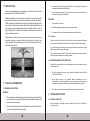
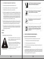
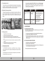
Tillage
Haulage
Landscaping
Crop Protection
Harvest
Post Harvest
Seeding & Plantation
Solutions...
Sub Soiler
World Class Farm Equipment
BERI UDYOG PVT LTD
Corporate Office:
Plot No. 235 to 240, Sec-3, HSIIDC, Karnal- 132001 (Haryana), India
+91 184 2221571/ 72/ 73
[email protected], www.fieldking.com
?
Operator Manual ?
Service Manual ?
Part Catalogue
CONGRATULATIONS!
You have invested in one of the best implements of its type in the market today.
The care you give your “FIELDKING” implement will greatly determine your
satisfaction with its performance and its service life. A careful study of this manual
will give you a thorough understanding of your new implement before operating.
If your manual is lost or destroyed, “FIELDKING” will be glad to provide you a new
copy. Visit to nearest dealership & get a copy. Most of our manuals can also be
downloaded from our website at www.fieldking.com.
As an authorized “FIELDKING” dealer, we stock genuine “FIELDKING” parts which
are manufactured with the same precision and skill as our original equipment. Our
trained service persons are well informed on methods required to service
“FIELDKING” equipments and are ready to help you.
Should you require additional information or assistance, please contact us.
YOUR AUTHORIZED
FIELDKING DEALER
BECAUSE “FIELDKING” MAINTAINS AN ONGOING PROGRAMME
OF PRODUCT IMPROVEMENT, WE RESERVE THE RIGHT TO MAKE
IMPROVEMENTS IN DESIGN OR CHANGES IN SPECIFICATION
WITHOUT INCURRING ANY OBLIGATION TO INSTALL THEM ON
UNITS PREVIOUSLY SOLD. BECAUSE OF THE POSSIBILITY THAT
SOME PHOTOGRAPHS IN THIS MANUAL WERE TAKEN OF
PROTOTYPE MODELS, PRODUCTION MODELS MAY VARY IN
SOME DETAIL. IN ADDITION, SOME PHOTOGRAPHS MAY SHOW
SHIELDS REMOVED FOR THE PURPOSE OF CLARITY. NEVER
OPERATE THIS IMPLEMENT WITHOUT ALL SHIELDS IN PLACE.
TO THE PURCHASER
This manual contains valuable information about your new “FIELDKING” sub soiler.
It has been carefully prepared to give you helpful suggestions for operating,
adjusting, servicing and ordering spare parts.
Keep this manual in a convenient place for quick and easy reference. Study it
carefully. You have purchased a dependable and sturdy sub soiler but only by proper
care and operation you can expect to receive the service and long life designed and
built into it.
Sometime in the future your sub soiler may need new parts to replace which are
worn out or broken. If so, go to your dealer and provide him equipment’s detail like
model and part number.
PURCHASER / OPERATOR’S RESPONSIBILITY
1. Read and understand the information contained in this manual.
2. Operate, lubricate, assemble and maintain the equipment in accordance with all
instructions and safety procedures in this manual.
3. Inspect the equipment and replace or repair any parts that are damaged or worn
out which under continued operation would cause damage, wear to other parts,
or cause a safety hazard.
4. Return the equipment or parts to the authorized “FIELDKING” dealer, from where
it was purchased, for service or replacement of defective parts that are covered
by warranty. (The “FIELDKING” Factory may inspect equipment or parts before
warranty claims are honored.)
5. All costs incurred by the dealer for traveling to or transporting the equipment for
warranty inspection and claims will be borne by the customer.
CUSTOMER INFORMATION
Name ______________________________________________
Purchased From ______________________________________
Date of Purchase _____________________________________
Model No. ___________________________________________
Serial No. ___________________________________________
INDEX
1.
INTRODUCTION
2.
TECHNICAL INFORMATION
3.
4.
5.
6.
2.1
General description
2.2
Warranty
2.3
Warranty become void
USAGE INSTRUCTIONS
3.1
Overall check -up
3.2
Attaching sub-soiler to the tractor
3.3
Safety Instruction
TRACTOR PREPARATION AND WORKING
4.1
Instructions for tractor preparation
4.2
Width of cut adjustment
4.3
Leveling the sub-soiler
4.4
Adjustments for deeper penetration
4.5
Warning for driver
4.6
Trouble shooting
MAINTENANCE
5.1
Maintenance Instructions
5.2
Storage of Machine after work
PICTURES AND PART CODE NO. FOR TRACTOR OPERATOR/DRIVER
3. It preserves moisture during high rainfall which is very important for the crop to
withstand low rainfall or drought periods.
1.1 INTRODUCTION
This manual contains the use and maintenance instructions with a list of the
spare parts of the “FIELDKING” Sub-Soiler.
Fieldking sub-soiler is used to break-up compacted soil layers and open the
ground up, so that roots and moisture can penetrate more deeply into the soil.
Yields suffer when compaction keeps roots from growing freely throughout the
soil in search of moisture and nutrients. Sub-soiler usage lets plants to stretch
their roots by opening passageways through the hardpan. It can be used as a
primary tillage tool i.e. one used for the first pass over a field but not normally a
part of usual tillage operation.
This implement is useful when a plow pan or hard pan (compacted layer) has
developed because of regular plowing and disking or heavy animal and
equipment traffic. When operated properly in dry soil this implement fractures
and shatters the hard soil.
4. It is an inexpensive implement & it provides a simple and economical way to
obtain boosting crop yields and profits.
FEATURES
1. It can go up to 55 cm deep.
2. It fights drought by increasing the ground storage capacity.
3. It increases soil turnover by reaching deeper organic matter layers.
2.2 Warranty
When the machine is delivered, check that it has not been subjected to damage
during transport and that the accessories are in a perfect condition and complete.
Any claims following the receipt of damaged goods shall be presented in writing
within 8 days from the receipt of the goods.
The purchaser may only make the claims under guarantee when he has complied
with the warranty conditions in the supply contract.
2.3 WHEN THE WARRANTY BECOMES VOID
Besides the cases specified in the supply agreement, the guarantee shall in any
case become void:
1. When the implement has been used beyond the specified power limit like
(Tractor Horse Power)
Fig-1 root growth after use of Sub-Soiler
2. TECHNICAL INFORMATION
2. When repairs made by the customer without authorization from the
manufacturer or owing to installation of spurious spare parts, the machine is
subjected to variations and the damage can be ascribed to these variations.
2.1 GENERAL DESCRIPTION
3. When the user has failed to comply with the instructions in this handbook.
BENEFITS
3. USAGE INSTRUCTIONS
1. The sub-soilers are deep tillage implements specially designed for breaking
up hard pan layers and loosening the subsoil allowing better drainage, root
growth and mineral osmosis.
2. The heavy duty chisel pointed share shatters the soil well below the surface,
thus increasing the water holding capacity.
1
3.1. OVERALL CHECK-UP
Before mounting of Sub-Soiler to tractor make sure that all nuts and bolts are
properly secured.
2
3.2.
ATTACHING THE SUB-SOILER TO THE TRACTOR
In order to protect yourself always wear adequate
clothes and shoes during the operations.
1. Place the sub-soiler duly levelled on the flat piece of land.
2. Reverse the tractor to the sub-soiler ( Do not drag the sub-soiler)
3. Attach the left arm of the tractor to the sub-soiler first.
4. Attach the lower right arm, turn the screw until the mounting pin is at the
same level as the hole on the tractor arm. If the gap between hole and
mounting pin is too close or too distant, turn the control arm in or pull it away
to an appropriate distance. You may have to adjust both height and distance
at the same time. When the hole at tractor arm and mounting pin are even,
insert the pin in the hole and lock it with the lynch pin.
5. Attach the central arm to the sub-soiler. To attach, turn the screws on both
sides to an equal length. If the arm is too short or too long, turn the screw to
adjust both at the same time until aligned with the hole on the central arm.
6. After attaching the sub-soiler lift it and adjust the control arm parallel to the
ground. When you look from both rear or sideways, the shanks should all be
touching the ground uniformly.
3.3 SAFETY
Never allow riders on the tractor or implement
unless an additional seat is available.
Be careful when moving around steep gradient to
avoid sharp turn.
Never transport the implement on rough roads
during the night. When operating, avoid sharp
turns that may cause tractor colliding with the
implement.
DANGER
Understanding the Machine Safety Labels
4. TRACTOR PREPARATION AND WORKING
4.1 INSTRUCTION FOR TRACTOR PREPARATION
The machine safety labels shown in this section are
placed in important areas on your machine to draw
attention to potential safety hazards
On your machine the words DANGER, WARNING, and
CAUTION are used with this safety-alert symbol.
DANGER identifies the most serious hazards.
Safety-Alert Symbol
The operator’s manual also explains any potential
safety hazards whenever necessary.
The following are typical instructions for preparing a tractor for operation:
1. The horsepower of tractor selected should match the implement.
2. All sub-soiler adjustment should be carried out.
3. Select draft and position control setting according to tractor operators manual.
4.2 Width/Depth adjustment
The width adjustment is available in three arms sub-soiler. Width of shanks could be
adjusted easily with the flexibility provided in the frame. The depth adjustment can
be done by changing the hole position in the shank for both two and three arm subsoiler. The single arm sub-soiler has no adjustment.
3
4
4.3 Leveling the sub-soiler
The level of the sub-soiler is controlled by the tractor top link. Lateral levelling is
controlled by adjusting the length of the tractor right lower link. These
adjustments must be made with the sub-soiler prior to operation.
4.4 Adjustment for deeper penetration
The depth of the penetration can be obtained by the position and draft control
levers of the tractor hydraulic system. Higher the tractor power more is the
depth of operation. However more depth can be obtained by lowering the
shanks.
if you encounter a problem that is difficult to solve, even after having read
through this trouble shooting section, Please call your local “FIELDKING”
Dealer. Before you call, please have this operator's manual & the serial
number from your Sub-Soiler ready.
PROBLEM
CAUSE
SOLVE
Blade won't penetrate
soil
Hard ground
condition
1. Replace blade if badly worn.
2. Be sure 3 point hitch is set in
"float" or "draft" Mode.
3. Set Shank angle
4. Add weight to frame
High power required.
1. Wrong Shank
Angle
2. Blade worn
1. Reset Shank Angle.
2. Replace blade.
5. MAINTENANCE
Fig 2- Soil fracturing pattern
4.5 Warning for driver
1.
2.
3.
4.
Operate the tractor in low first gear.
Lift the sub-soiler completely on every turn.
Never reverse the tractor when the sub-soiler is engaged in the soil.
Properly mount the three point linkage as mentioned above & lock with lynch
pin.
5. If subs-soiler stuck with tree roots and stones, stop tractor and lift the
subsoiler.
6. Keep proper distance from sub-soiler when it is in working.
7. Lift the sub-soiler completely during transport.
4.6 TROUBLING SHOOTING
The “FIELDKING” Sub-Soiler Uses a vertical Shank to break- up Hardpan,
trench or aerate the soil. it is a simple and reliable system that requires minimal
maintenance.
5.1 MAINTENANCE INSTRUCTIONS
If sub-soiler is working on stony land then maintenance goes up. Please follow
these rules to get the best results:
1. If sub-soiler is new then tightened all nuts and bolts after few trials runs.
2. Constantly check for tightness of nuts and bolts.
3. When the length of the points is reduced by 1 inch, reverse it and use the
other side of the points, when both side of the strip are worn out replace it
with the new one.
5.2 STORAGE OF MACHINE AFTER WORK
1. Wash the sub-soiler completely after work.
2. Replace the worn out nuts and bolts.
3. If sub-soiler has to remain unused for long time then clean it & apply a layer
of un-used oil/grease for rust prevention.
These steps will enhance the life of your sub-soiler
in the following section, we have listed many of the problems, causes & solutions
to the problems that you may encounter.
5
6
6. PART CATALOUGE OF 1, 2 & 3 ARM SUB-SOILER
SR. NO.
1
2
3
4
5
6
7
8
9
10
11
12
13
14
15
16
PART NO.
FKSS-501
FKSS-502
FKSS-503
FKSS-504
FKSS-005
10020013
10270007
10280041
10260080
10280005
10280025
10260102
10270003
10260052
10270005
10020096
PART NAME
FRAME ASSEMBLY
LINKAGE
TYNE ASSEMBLY
STANP PIPE ASSEMBLY
SIDE LINK SUPPORT
HITCH PIN 20MM
SPRING WASHER 25MM
PLAIN NUT M25
HEX HEAD BOLT M16x80x2P
NYLOCK NUT M16x2P
NYLOCK NUT M12x1.75P
HEX. HEAD BOLT M12x65x1.75P
SPRING WASHER 12MM
HEX HEAD BOLT M12x40x1.75P
SPRING WASHER 16MM
R-PIN 6x10⁶MM
SUB-SOILER (1-RAM)
7
QTY.
1
1
1
2
2
2
4
2
2
3
2
2
2
1
2
2
SR.NO.
PART NO.
PART NAME
QTY.
1
2
3
4
5
6
7
8
9
10
FKSS-008
FKSS-009
FKSS-010
10260080
10280005
10260052
10260050
10280025
10270005
10270003
SUB SOILER TYNE
SUB SOILER SHOWEL
SUB SOILER SHOE
HEX. HEAD BOLT M16x80x2P
NYLOCK NUT M16x2P
CSK BOLT M12x40x1.75P
CSK BOLT M12x50x1.75P
NYLOCK NUT M12x1.75P
SPRING WASHER 16MM
SPRING WASHER 12MM
1
1
1
2
2
1
1
2
2
2
TYNE ASEMBLY SUB-SOILER (1-ARM)
8
SR.NO.
PART NO.
PART NAME
QTY.
1
2
3
4
5
6
7
8
9
10
11
FKSS-505
FKSS-506
FKSS-507
FKSS-508
10260080
10270005
10280005
10020098
10260082
10270006
10280006
FRAME ASSEMBLY
3 PT LINKAGE ASSEMBLY
TYNE ASSEMBLY
STAND ASSEMBLY
HEX. HEAD BOLT (M16x80x2P)
SPRING WASHER (16MM)
NYLOCK NUT (M16x2P)
R PIN (6x10⁶MM)
HEX. HEAD BOLT (M18x60x1.5P)
SPRING WASHER (18MM)
NYLOCK NUT (M18x1.5P)
1
1
2
1
7
7
7
1
2
2
2
SUB-SOILER (2-ARM)
9
SR.NO.
PART NO.
PART NAME
QTY.
1
2
3
4
5
6
7
8
FKSS-020
FKSS-009
FKSS-010
10260049
10280025
10260080
10260050
10270003
SUB SOILER TYNE
SUB SOILER SHOWEL
SUB SOILER SHOE
CSK BOLT (M12x40x1.75P)
NYLOCK NUT (M12x1.75P)
HEX. HEAD BOLT (M16x80x2P)
CSK BOLT (M12x50x1.75P)
SPRING WASHER (12MM)
1
1
1
2
4
2
2
4
SUB-SOILER TYNE ASSEMBLY (2 & 3 ARM)
10
DELIVERY CHECKLIST
Dealer Pre-Delivery (Please Tick)
1. Dealer Pre-Delivery Checklist
Dealer Information
1.
The customer or person responsible has
been given the operator’s manual.
Dealer’s Name..............................................................................
2.
The customer undertakes to read the
c o m p l e t e o p e r a t o r ’s m a n u a l a n d
understands all aspects of the manual
before operation of the machine.
3.
4.
5.
SR.NO.
PART NO.
PART NAME
QTY.
1
2
3
4
5
6
7
8
9
10
11
12
13
14
15
FKSS-509
FKSS-510
FKSS-507
FKSS-029
FKSS-508
10260050
10260049
10260017
10260080
10260082
10270005
10270006
10020096
10280006
10260135
FRAME ASSEMBLY
3 PT. LINKAGE
TYNE ASSEMBLY
FRONT SUPPORT PIPE
STAND PIPE ASSEMBLY
CSK BOLT (M12X50X1.75P)
CSK BOLT (M12X40X1.75P)
HEX HEAD BOLT (M16X60X2P)
HEX HEAD BOLT (M16X80X2P)
HEXHEAD BOLT (M18X60X1.5P)
SPRING WASHER (16MM)
SPRING WASHER (18MM)
R PIN (6X10⁶MM)
NYLOCK NUT (M18X1.5P)
HEX HEAD BOLT (M16X110X2P)
1
1
3
1
1
3
3
6
6
4
12
4
1
4
1
Please Complete all Dealer information Below
Address........................................................................................
.......................................................................................................
State........................................... Postcode.................................
Phone.......................................... Fax..........................................
All safety, operational and maintenance
information have been explained and
demonstrated.
Email.............................................................................................
Service Person..............................................................................
All greasing and oil points, stickers,
guarding and ID plate have been identified
and physically pointed out.
I confirm that the pre-delivery service was performed on this machine.
The customer agrees that it is his
responsibility to read and carry out the
safety, maintenance and operation as per
this operator’s manual.
Date..............................................................................................
Customer Delivery (Please Tick)
Please Complete all Customer Information Below
Signature.......................................................................................
Comments.....................................................................................
.......................................................................................................
.......................................................................................................
2. Customer Delivery Checklist
Customer Information
1.
The customer or person responsible has
been given the operator’s manual.
Customer’s Name.........................................................................
2.
The customer undertakes to read the
c o m p l e t e o p e r a t o r ’s m a n u a l a n d
understands all aspects of the manual
before operation of the machine.
3.
4.
5.
Address........................................................................................
.......................................................................................................
State........................................... Postcode.................................
Phone.......................................... Fax..........................................
All safety, operational and maintenance
information have been explained and
demonstrated.
Email.............................................................................................
All greasing and oil points, stickers,
guarding and ID plate have been identified
and physically pointed out.
I confirm that all of the delivery checks were explained and performed.
Delivery Person.............................................................................
Signature.......................................................................................
Delivery Date................................................................................
The customer agrees that it is his
responsibility to read and carry out the
safety, maintenance and operation as per
this operator’s manual.
Comments.....................................................................................
.......................................................................................................
.......................................................................................................
SUB-SOILER (3-ARM)
11
12
WARRANTY CARD
Customer Copy
CUSTOMER NAME Mr./ Mrs :
ADDRESS
:
MOBILE NO.
:
Email
:
NAME OF IMPLEMENT
:
MODEL NO.
:
YEAR OF Mfg.
:
SERIAL NO.
:
REGISTRATION NO.
:
DATE OF PURCHASING
:
NAME OF DEALER
:
Customer`s Signature
Dealer`s Signature
BERI UDYOG PVT LTD
Corporate Office:
Plot No. 235 to 240, Sec-3, HSIIDC, Karnal- 132001 (Haryana), India
+91 184 2221571/ 72/ 73
[email protected], www.fieldking.com
13
14
WARRANTY CARD
Company Copy
CUSTOMER NAME Mr./ Mrs :
ADDRESS
:
MOBILE NO.
:
Email
:
NAME OF IMPLEMENT
:
MODEL NO.
:
YEAR OF Mfg.
:
SERIAL NO.
:
REGISTRATION NO.
:
DATE OF PURCHASING
:
NAME OF DEALER
:
Customer`s Signature
Dealer`s Signature
BERI UDYOG PVT LTD
Corporate Office:
Plot No. 235 to 240, Sec-3, HSIIDC, Karnal- 132001 (Haryana), India
+91 184 2221571/ 72/ 73
[email protected], www.fieldking.com
15
16
WARRANTY CARD
Dealer Copy
CUSTOMER NAME Mr./ Mrs :
ADDRESS
:
MOBILE NO.
:
Email
:
NAME OF IMPLEMENT
:
MODEL NO.
:
YEAR OF Mfg.
:
SERIAL NO.
:
REGISTRATION NO.
:
DATE OF PURCHASING
:
NAME OF DEALER
:
Customer`s Signature
Dealer`s Signature
BERI UDYOG PVT LTD
Corporate Office:
Plot No. 235 to 240, Sec-3, HSIIDC, Karnal- 132001 (Haryana), India
+91 184 2221571/ 72/ 73
[email protected], www.fieldking.com
17
18