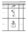
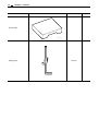
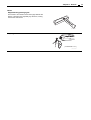
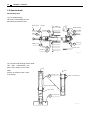
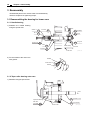
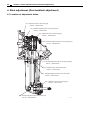
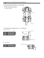
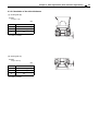
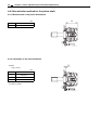
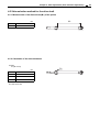
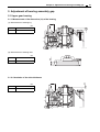
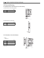
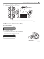
1
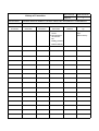
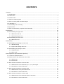
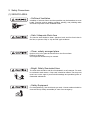
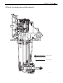
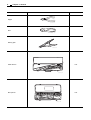
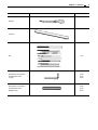
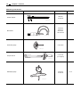
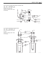
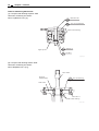
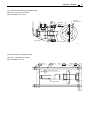
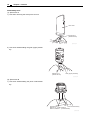
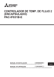
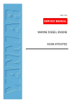
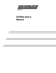
Document No.
History of Correction
Manual Name:
Page No.
M2215-04E140
1
YANMAR SERVICE MANUAL FOR SAIL DRIVE UNIT SD40/SD40-4T & SD50/SD50-4T
UNIT Model:
SD40/SD40-4T, SD50/SD50-4T
No.of
Correction
Date of
Correction
-
Mar. 2005
Cause for
Correction
Outline of
Correction
Added SD50/-4T (1) Added SD50
series.
(2) Changed document number.
M9961-H13030
L
M2215-04E140
Corrected Item
Number
-
Corrected
by:
Quality Control
Dept.
Marine factory
CONTENTS
1 General ............................................................................................................................................................ 1
1.1 Specifications ........................................................................................................................................... 1
1.2 Exterior view ............................................................................................................................................. 2
1.3 Sectional view .......................................................................................................................................... 3
1.4 Criteria for replacing parts ........................................................................................................................ 4
1.5 Route of cooling water and lubricating oil ................................................................................................ 5
1.6 Lubricating oil ........................................................................................................................................... 6
1.7 Disassembly and reassembly .................................................................................................................. 7
1.8 Special tools ........................................................................................................................................... 14
1.9 Notes on disassembly, inspection and reassembly ............................................................................... 19
2 Disassembly ................................................................................................................................................... 20
2.1 Disassembling the upper case ............................................................................................................... 20
2.1.1 Removal of the unit ...................................................................................................................... 20
2.1.2 Disassembling the unit ................................................................................................................. 27
2.2 Disassembling the lower case ................................................................................................................ 32
2.2.1 Removal of unit ............................................................................................................................ 32
3 Reassembly ................................................................................................................................................... 38
3.1 Reassembling the bearing for lower case .............................................................................................. 38
3.1.1 Needle bearing ............................................................................................................................ 38
3.1.2 Taper roller bearing outer race .................................................................................................... 38
3.2 Reassembling the bearings of shaft ....................................................................................................... 39
3.2.1 Propeller shaft .............................................................................................................................. 39
3.2.2 Drive shaft .................................................................................................................................... 39
4 Shim adjustment (Gear backlash adjustment) ............................................................................................... 40
4.1 Location of adjustment shims ................................................................................................................. 40
4.2 Measurement of the dimensions of the cases ........................................................................................ 41
4.2.1 Upper case .................................................................................................................................. 41
4.2.2 Lower case
....................................................................... 41
4.3 Shim selection method for the clutch shaft ............................................................................................ 42
4.3.1 Measurement of the dimensions (L1, L2, L3) of the gear ............................................................ 42
4.3.2 Calculation of the shim thickness ................................................................................................ 43
4.4 Shim selection method for the pinion shaft ............................................................................................ 44
4.4.1 Measurement of the pinion dimensions ....................................................................................... 44
4.4.2 Calculation of the shim thickness ................................................................................................ 44
4.5 Shim selection method for the drive shaft .............................................................................................. 45
4.5.1 Measurement of the dimensions (M1) of the pinion ..................................................................... 45
4.5.2 Calculation of the shim thickness ................................................................................................ 45
4.6 Shim selection method for the propeller shaft ........................................................................................ 46
4.6.1 Measurement of the dimensions (M3) of the gear ....................................................................... 46
4.6.2 Calculation of the shim thickness ................................................................................................ 46
5 Adjustment of bearing assembly gap ............................................................................................................. 47
5.1 Upper gear bearing ................................................................................................................................ 47
5.1.1 Measurement of the dimension (L6) of the bearing ..................................................................... 47
5.1.2 Calculation of the shim thickness ................................................................................................ 47
5.2 Pinion shaft bearing ............................................................................................................................... 48
5.2.1 Measurement of the dimension (L4) of the bearing ..................................................................... 48
5.2.2 Calculation of the shim thickness ................................................................................................ 48
5.3 Pinion drive shaft bearing ....................................................................................................................... 49
5.3.1 Measurement of the dimension (M2) of the bearing .................................................................... 49
5.3.2 Calculation of the shim thickness ................................................................................................ 49
5.4 Propeller shaft bearing ........................................................................................................................... 50
5.4.1 Measurement of the dimension (M4) of the bearing .................................................................... 50
5.4.2 Calculation of the shim thickness ................................................................................................ 50
6 Adjustment of the gear backlash .................................................................................................................... 51
6.1 Upper gear ............................................................................................................................................. 51
6.2 Lower gear ............................................................................................................................................. 52
7 Adjustment of the gear dye pattern ................................................................................................................ 53
7.1 Upper gear ............................................................................................................................................. 53
7.2 Propeller shaft ........................................................................................................................................ 54
8 Adjustment of the shift lever ........................................................................................................................... 55
8.1 Measurement of the dimensions (H, A) .................................................................................................. 55
8.1.1 Shift Lever bolt ..................................................................... 55
8.1.2 Shifter pin position ....................................................................................................................... 55
8.2 Calculation of the shim thickness ........................................................................................................... 56
8.3 Caution of reassembly ........................................................................................................................... 56
9 Tightening torque for nuts and bolts ............................................................................................................... 57
FOR SAFETY
1. SAFETY LABELS
• Most accidents are caused by negligence of basic safety rules and precautions. For accident
prevention, it is important to avoid such causes before development to accidents.
Please read this manual carefully before starting repair or maintenance to fully understand safety
precautions and appropriate inspection and maintenance procedures.
Attempting at a repair or maintenance job without sufficient knowledge may cause an unexpected
accident.
• It is impossible to cover every possible danger in repair or maintenance in the manual. Sufficient
consideration for safety is required in addition to the matters marked
. Especially for
safety precautions in a repair or maintenance job not described in this manual, receive instructions
from a knowledgeable leader.
• Safety marks used in this manual and their meanings are as follows:
DANGER-indicates an imminent hazardous situation which, if
not avoided, WILL result in death or serious injury.
WARNING-indicates a potentially hazardous situation which, if
not avoided, COULD result in death or serious injury.
CAUTION-indicates a potentially hazardous situation which, if
not avoided, may result in minor or moderate injury.
• NOTICE - indicates that if not observed, the product performance or quality may not be
guaranteed.
2. Safety Precautions
(1) SERVICE AREA
• Sufficient Ventilation
Inhalation of exhaust fumes and dust particles may be hazardous to ones
health. Running engines welding, sanding, painting, and polishing tasks
should be only done in well ventilated areas.
• Safe / Adequate Work Area
The service area should be clean, spacious, level and free from holes in
the floor, to prevent "slip" or "trip and fall" type accidents.
• Clean, orderly arranged place
No dust, mud, oil or parts should be left on the floor surface.
[Failure to Observe]
An unexpected accident may be caused.
• Bright, Safely Illuminated Area
The work area should be well lit or illuminated in a safe manner. For work
in enclosed or dark areas, a "drop cord" should be utilized. The drop cord
must have a wire cage to prevent bulb breakage and possible ignition of
flammable substances.
• Safety Equipment
Fire extinguisher(s), first aid kit and eye wash / shower station should be
close at hand (or easily accessible) in case of an emergency.
(2) WORK - WEAR (GARMENTS)
• Safe Work Clothing
Well fitting !!
Appropriate safety wear (gloves, special shoes/boots, eye/ear protection,
head gear, harness', clothing, etc.) should be used/worn to match the task
at hand. Avoid wearing jewelry, unbuttoned cuffs, ties or loose fitting
clothes around moving machinery. A serious accident may occur if caught
in moving/rotating machinery.
(3) TOOLS
• Appropriate Lifting / Holding
When lifting an engine, use only a lifting device (crane, jack, etc.) with
sufficient lifting capacity. Do not overload the device. Use only a chain,
cable, or lifting strap as an attaching device. Do not use rope, serious
injury may result.
To hold or support an engine, secure the engine to a support stand, test
bed or test cart designed to carry the weight of the engine. Do not
overload this device, serious injury may result.
Never run an engine without being properly secured to an engine support
stand, test bed or test cart, serious injury may result.
• Appropriate Tools
Always use tools that are designed for the task at hand. Incorrect usage
of tools may result in damage to the engine and or serious personal injury.
(4) GENUINE PARTS and MATERIALS
• Genuine Parts
Always use genuine YANMAR parts or YANMAR recommended parts and
goods. Damage to the engine, shortened engine life and or personal
injury may result.
(5) FASTENER TORQUE
• Torquing Fasteners
Always follow the torque values and procedures as designated in the
service manual. Incorrect values, procedures and or tools may cause
damage to the engine and or personal injury.
(6) Electrical
• Short Circuits
Always disconnect the (-) Negative battery cable before working on the
electrical system. An accidental "short circuit" may cause damage, fire
and or personal injury. Remember to connect the (-) Negative battery
cable (back onto the battery) LAST
• Charging Batteries
Charging wet celled batteries produces hydrogen gas. Hydrogen gas is
extremely explosive. Keep sparks, open flame and any other form of
ignition away. Explosion may occur causing severe personal injury.
• Battery Electrolyte
Batteries contain sulfuric acid. Do NOT allow it to come in contact with
clothing, skin and or eyes, severe burns will result.
(7) WASTE MANAGEMENT
Observe the following instructions with regard to hazardous waste
disposal. Negligence of these will have a serious impact on environmental
pollution concerns.
1) Waste fluids such as lube oil, fuel and coolant shall be carefully put
into separate sealed containers and disposed of properly.
2) Do NOT dispose of waste materials irresponsibly by dumping them
into the sewer, overland or into natural waterways.
3) Waste materials such as oil, fuel, coolant, solvents, filter elements and
batteries, must be disposed of properly according to local ordinances.
Consult the local authorities or reclamation facility.
(8) FURTHER PRECAUTIONS
• Fueling / Refueling
Keep sparks, open flames or any other form of ignition (match, cigarette,
etc.) away when fueling/refueling the unit. Fire and or an explosion may
result.
• Hot Surfaces.
Do NOT touch the engine (or any of its components) during running or
shortly after shutting it down. Scalding / serious burns may result. Allow
the engine to cool down before attempting to approach the unit.
• Rotating Parts
Be careful around moving/rotating parts. Loose clothing, jewelry, ties or
tools may become entangled causing damage to the engine and or
severe personal injury.
• Preventing burns from scalding
1) Never open the filler cap shortly after shutting the engine down.
Steam and hot water will spurt out and seriously burn you. Allow the
engine to cool down before attempt to open the filler cap.
2) Securely tighten the filler cap after checking the cooling water.
Steam can spurt out during engine running, if tightening loose.
• Safety Label Check
Pay attention to the product safety label.
A safety label (caution plate) is affixed on the product for calling special
attention to safety.
If it is missing or illegible, always affix a new one.
3. Precautions for Service Work
(1) Precautions for Safety
Read the safety precautions given at the beginning of this manual carefully and always mind safety in
work.
(2) Preparation for Service Work
Preparation is necessary for accurate, efficient service work. Check the customer ledger file for the
history of the engine.
• Preceding service date
• Period/operation hours after preceding service
• Problems and actions in preceding service
• Replacement parts expected to be required for service
• Recording form/check sheet required for service
(3) Preparation before Disassembly
• Prepare general tools, special service tools, measuring instruments, oil, grease, non-reusable parts,
and parts expected to be required for replacement.
• When disassembling complicated portions, put match-marks and other marks at places not
adversely affecting the function for easy reassembly.
(4) Precautions in Disassembly
• Each time a parts is removed, check the part installed state, deformation, damage, roughening,
surface defect, etc.
• Arrange the removed parts orderly with clear distinction between those to be replaced and those to
be used again.
• Parts to be used again shall be washed and cleaned sufficiently.
• Select especially clean locations and use clean tools for disassembly of hydraulic units such as the
fuel injection pump.
(5) Precautions for Inspection and Measurement
Inspect and measure parts to be used again as required to determine whether they are reusable or not.
(6) Precautions for Reassembly
• Reassemble correct parts in correct order according to the specified standards (tightening torques,
and adjustment standards). Apply oil important bolts and nuts before tightening when specified.
• Always use genuine parts for replacement.
• Always use new oil seals, O-rings, packing and cotter pins.
• Apply sealant to packing depending on the place where they are used. Apply of grease to sliding
contact portions, and apply grease to oil seal lips.
(7) Precautions for Adjustment and Check
Use measuring instruments for adjustment to the specified service standards.
Chapter 1 General
1 General
1.1 Specifications
Item
Unit
Model
Contents
SD40-3, SD50-3
SD40-4, SD50-4
Clutch system
Cone clutch
Reduction gear system
Bevel gear
Direction of rotation
Reduction ratio
Input shaft
Counter-clockwise viewed from stern
Propeller shaft
Counter-clockwise or clockwise viewed from stern
Ahead
2.32
Astern
2.32
Lubrication system
Splash lubrication
Lub.oil capacity
L
Dry mass
kg
Applicable eng.
SD40-4T, SD50-4T
Model
Output (DIN6270B)
2.2 (SD40 old type 1.8)
39
3JH3CE
3JH4CE
41
4JH3CE
4JH4CE
4JH3-TCE
kW (PS)
29.4(40)/3800 29.4(40)/3000 41.2(56)/3800 40.5(55)/3000
55.2(75)/3800
Allowable torque
N•m (kgf•m)
129(13.1)
140(14.3)
Allowable speed at Input shaft
min-1 (rpm)
API service grade GL4 or higher,SAE80W-90 Quicksilver high
or 90(High performance gear lube, as shown performance gear
on the right, is also acceptable.)
lube.
Lube oil
Max. propeller dia.
4000
mm (inch)
Mounting size
Sealing method for bottom of ship
Engine installation direction
Quicksilver® is registered trademark of Brunswick Corporation.
457(18)
SAE #5
SAE #4
Double
180° Acceptable
1
2
Chapter 1 General
1.2 Exterior view
Mounting flange
Shift lever
Oil supply port
Upper gear case
Clamp (Remote control cable)
Diaphragm (B)
Damper rubber
Diaphragm (A)
Lower gear case
Propeller
002949-00E
Chapter 1 General
1.3 Sectional view
Upper pinion
Taper roller bearing
Double angular bearing
Pinion shaft
Gear
Cone clutch
Clutch shaft
Drive cone
Gear
Sleeve
Spacer
Needle bearing (A)
Taper roller bearing
Drive shaft
Taper roller bearing
Needle bearing (B)
Oil seal
Lower pinion
Propeller shaft
Taper roller bearing
Lower gear
Anti-corrosive zinc
Drain plug
002950-01E
3
4
Chapter 1 General
1.4 Criteria for replacing parts
Criteria for replacement
Standard value
Bearing
Needle bearing (A)
(K24 x 28 x 17)
Standard service life
Evidence of needle flaking or loss
Every 1500 hours
Anti-corrosive zinc
Weight : <=400 g (with plug)
A half year or less than 1/2
of its original size
Oil seals
1) Lip hardening or hair cracks
2) Disassembly
Every 1000 hours or 2 years
O-ring
Disassembly
Diaphragms (A) & (B)
Hair cracks
Steel band
Disassembly
Needle bearing (B)
2 years
Chapter 1 General
1.5 Route of cooling water and lubricating oil
Cooling water
Lubricating oil
002951-00E
5
6
Chapter 1 General
1.6 Lubricating oil
(1) Choice of lube oil
The selection of lube oil is very important to a Sail-drive. If an unsuitable oil is used, or oil change is neglected,
it may result in damage and a shorter Sail-drive life. When selecting the lube oil, it must be one of the following.
(2) Kind of lube oil
See 1.2 specifications.
(3) Lube oil viscosity
The viscosity of the lube oil greatly influences Sail-drive performance.
SD40, SD50
Supplier
Brand name
API service
SAE No.
SHELL
Shell Spilax oil EP 90
GL-4
90
SHELL
Shell Spilax oil HD 90
GL-5
90
CALTEX
Multipurpose thuban EP
GL-4,GL-5
90
MOBIL
Mobilub HD 80W-90
GL-5
80W-90
ESSO
Esso gear oil GP 90
GL-4
90
ESSO
Esso gear oil GP 90
GL-5
90
SD40-4T, SD50-4T
Quicksilver®
High performance gear lube
Quicksilver® is registered trademark of Brunswick Corporation.
Chapter 1 General
1.7 Disassembly and reassembly
The following tools are necessary when disassembling and reassembling the sail drive unit.
These tools must be used according to disassembly process and location.
General hand tools
Name
Illustration
Remarks
Spanner
001385-00X
Screwdriver for +
(Cross recessed head) screws
Screwdriver for (Philips head) screws
002952-00X
002953-00X
Steel hammer
001389-00X
Copper hammer
001390-00X
Mallet
001391-00X
10 x 13
12 x 14
17 x 19
21 x 23
21 x 24
7
8
Chapter 1 General
Name
Illustration
Remarks
Nipper
001392-00X
Plier
001393-00X
Starting plier
003262-00X
Offset wrench
1set
001394-00X
Box spanner
1set
001395-00X
Chapter 1 General
Name
Illustration
Remarks
Scraper
001396-00X
Lead rod
001397-00X
File
1set
001398-00X
Rod spanner for hexagon
socket head screws
(L-type)
5 mm
6 mm
8 mm
001399-00X
Rod spanner for hexagon
socket head screws
(Straight type)
002954-00X
5 mm
6 mm
8 mm
9
10
Chapter 1 General
Measuring instruments
Name
Illustration
Accuracy & range
Ref.
1/20 mm,
0-150 mm
Vernier calipers
001423-00X
1/100 mm,
0-25 mm,
25-50 mm,
100-125 mm
Micrometer
001424-00X
Thickness gauge
0.05-2 mm
001426-00X
0-147 N-m
(0-15 kgf-m)
Torque wrench
001427-00X
1/100 mm,
0-150 mm
Dial depth gauge
002955-00X
8.1.2
Chapter 1 General
Name
Illustration
Lever type
dial test indicator
Accuracy & range
Ref.
1/100 mm,
0-0.8 mm
6.1
003042-00X
Magnetic base
002956-00X
Clamp type
box block
100 mm (K-type)
002957-00X
11
12
Chapter 1 General
Name
Illustration
Accuracy & range
Surface plate
002958-00X
Height gauge
500 mm
002959-00X
Ref.
Chapter 1 General
Others
Supplementary packing agent
The surface to be coated must be thoroughly cleaned with
thinner or benzene and completely dry. Moreover, coating
must be thin and uniform.
D
ON
E B NO.50
RE
H
RT
PE
SU
002960-00X
Liquid gasket
[ THREEBOND 1215 ]
002961-00E
13
14
Chapter 1 General
1.8 Special tools
Reassembly tools
(1) For needle bearing
Use when reassembling the needle bearing to the lower case.
Name of tool
Part No.
Needle bearing
Washer 12
Nut 12
Tool 30/36
22137
120000
196420
92690
26711
120002
Bolt M12 x 100
196320
92700
Shaft
Tool 25/47
196420
92650
196440
92680
Tool NB28
26606
140002
Nut 14
24311
000160
O-ring P16
Lower case
196420
92660
003910-00E
(2) For taper roller bearing at drive shaft
Use
when
reassembling
the
taper roller bearing at the drive
shaft.
Press
Press
Press it as striking it with a hammer strongly.
196440
92110
Tool 34 x 120
Taper roller bearing
Taper roller bearing
Drive shaft
196440
92130
Tool 36 x 50
003911-01E
Chapter 1 General
15
(3) For outer race of taper roller bearing at propeller shaft
Use
when
reassembling
the
outer race of the taper roller
bearing to the lower case.
Press it as striking it with a hammer strongly.
Press
Outer race
Tool TB62
196440
92580
Lower case
196322
92620
Tool B17 x 25
196320
92640
Tool 25 / 100
003912-00E
(4) For taper roller bearing at propeller shaft
Use
when
reassembling
the
taper roller bearing at the propeller shaft.
Press it as striking it with a hammer strongly.
Press
Press
196312
92110
Tool 37 x L40
Taper roller bearing
Propeller shaft
196440
92120
196322
92550
Tool B90
196311
92510
Stand
Tool 43 x 20
003913-00E
16
Chapter 1 General
Tools for measuring dimensions
(1) For taper roller bearing at pinion shaft
Use when measuring the dimension of L4(Refer to 5.2.1(1)).
26116
120902
Bolt M12 x 90
196322
92260
Tool, U brg measure
Taper roller bearing
Upper pinion
22137
120000
26716
120002
Washe 12
Nut M12
003914-00E
(2) For taper roller bearing at drive shaft
Use when measuring the dimension of M2(Refer to 5.3.1(1)).
Drive shaft
Holes for
measurement
196440
92280
Tool, D shaft brg.
Lower case
M10 bolt x 4
Taper roller bearing
003915-00E
Chapter 1 General
17
(3) For taper roller bearing at propeller shaft
Use when measuring the dimension of M4(Refer to 5.4.1(1)).
Holes for
measurement
M10 bolt
196440
92290
Tool
Lower case
Propeller shaft
003916-01E
(4) For bevel gear on propeller shaft
Use when measuring the dimension of M3(Refer to 4.6.1).
26716
120002
Nut 12
196440
92260
196440
92250
Bolt
Nut 12
26716
120002
Stand
196440
92270
Tool, P shaft fixed
Propeller shaft
003917-00E
18
Chapter 1 General
Disassembly tools
(1) Special tool A
1) Use when removing the drive pinion end nut.
Lower case
Special tool A
(196320-92120)
003918-00E
2) Use when disassembling the gear (upper) assembly.
Special tool A
(196320-92120)
Gear (upper) assembly
003919-00E
(2) Special tool B
1) Use when disassembling the pinion shaft assembly.
Special tool B
Pinion shaft assembly
SD40 & 50 : (196440-92010)
SD40-4T, SD50-4T : (196440-92020)
002962-00E
Chapter 1 General
1.9 Notes on disassembly, inspection and reassembly
(1) Carefully note the correct mounting position before removing or disassembling the unit.
(2) To avoid mix-ups when disassembling, keep the parts in order.
(3) Use liquid gasket wherever necessary to prevent oil or water leakage.
(4) When the tightening torque is specified, tighten the bolt to the specified torque with a torque wrench.
(5) Always use new gaskets, packing, and o-rings when reassembling.
(6) Always use genuine YANMAR replacement parts.
(7) Some repairs require special tools in fully equipped workshops.
These repairs should be made with the proper tools and in the proper facilities.
(8) Disassemble in the order specified in this Service Manual.
19
20
Chapter 2 Disassembly
2 Disassembly
2.1 Disassembling the upper case
2.1.1 Removal of the unit
(1) Separation from the lower case
1) Remove the tightening bolts (M10) from the lower case.
Lower case
Tightening bolt
Upper case
003920-00E
2) Upper case separated from lower case.
Upper case
003921-00E
3) Lower case separated from upper case.
Lower case
003922-00E
Chapter 2 Disassembly
21
(2) Removal of the mounting flange
1) Remove the tightening bolts (M8) from the mounting
flange and the upper case.
Mounting flange
Tightening bolt
003028-00E
2) Removal of mounting flange.
Upper case
Mounting flange
002963-00E
3) Upper case removed from mounting flange.
Upper case
002964-00E
22
Chapter 2 Disassembly
(3) Removal of the Shift Lever and Support
1) Remove the support tightening bolt (M8).
Tightening bolt
Shift lever
Upper case
002965-00E
2) Remove the support.
Support
002966-00E
3) Shift lever assembly after removal.
Support
Shift lever
003923-00E
Chapter 2 Disassembly
23
(4) Removal of the pinion shaft assembly
1) Remove the pinion shaft assembly nuts.
Tightening nut
002967-00E
Pinion shaft
003924-00E
2) Remove the pinion shaft assembly from the upper case.
Pinion shaft assembly
003029-00E
3) Pinion shaft assembly after removal.
003030-00E
24
Chapter 2 Disassembly
(5) Removal of the gear (upper) assembly
1) Remove the upper cover tightening bolts (M8).
Tightening bolt
Upper cover
003031-00E
2) Remove the upper cover.
Upper cover
003032-00E
Clutch shaft edge face screw hole
003033-00E
3) Screw the gear (upper) assembly raising tool into the
thread (M8) of the clutch shaft edge face and lift out the
assembly.
Raising tool
Gear (upper) assembly
003034-00E
4) Gear (upper) assembly after removal.
003035-00X
Chapter 2 Disassembly
25
(6) Removal of the diaphragm
• Diaphragm A
Upper case
Seal flange
Diaphragm B
003036-00E
1) Remove the damper rubber mounting nut (M12) from the
upper case.
Upper case
Mounting nut
Damper rubber
003925-00E
2) Remove the diaphragm A which was installed on the
back of the upper case seal flange.
Diaphragm A
Seal flange
003926-00E
3) Diaphragm A after removal.
Diaphragm A
003927-00E
26
Chapter 2 Disassembly
• Diaphragm B
1) Remove the upper case bend.
Upper case
Band
Diaphragm B
003928-00E
2) Remove the seal flange band.
Seal flange
Band
003929-00E
3) Remove the upper case and the seal flange.
Upper case
Seal flange
003930-00E
4) Remove the diaphragm B from the upper case.
Upper case
Diaphragm B
003931-00E
5) Diaphragm B after removal.
Diaphragm B
003932-00E
Chapter 2 Disassembly
27
2.1.2 Disassembling the unit
(1) Disassembling the pinion shaft assembly
1) Remove the tightening bolt (M10) for pinion gear and the
pinion shaft assembly to disassemble.
Tightening bolt
Pinion shaft assembly
003933-00E
2) Insert the pinion shaft to the fixed special tool B (for stopping gear movement).
Pinion shaft
Special tool B
003934-00E
3) Remove the tightening bolt (M10).
Tightening bolt
003935-00E
4) Pinion shaft assembly after removal.
Pinion shaft
Bearing housing
Shim
Oil seal case
003936-00E
28
Chapter 2 Disassembly
5) Push out the pinion by using the press to separate the
pinion from bearing housing.
Bearing housing
003937-00E
6) Pinion and taper roller bearing separated from bearing
housing.
Taper roller bearing
Pinion
Bearing housing
003938-00E
Chapter 2 Disassembly
(2) Disassembling the gear (upper) assembly
1) Insert the clutch shaft to the fixed special tool A (for stopping gear movement)
Clutch shaft
Special tool A
003939-00E
2) The edge of the clutch shaft end nut (M16 x 1.5 left-hand
screw) is caulked to the clutch shaft.
Caulking
End nut
003940-00E
3) Lift up the caulking.
003941-00E
4) Remove the end nut.
End nut
003942-00E
5) Pull out the gear, clutch ring and bearing as a unit.
Gear, clutch ring,
bearing set
003943-00E
29
30
Chapter 2 Disassembly
6) Gear, clutch ring and bearing as a unit after removal.
End nut
Gear, clutch ring, bearing set
004751-00E
Spacer
Drive cone
004752-00E
004753-00X
7) Gear (upper) assembly after disassembly.
Spacer
Drive cone
Gear,
clutch ring,
bearing set
End nut
Clutch shaft
004754-01E
Chapter 2 Disassembly
31
(3) Disassembling the shift lever assembly
Shifter
Support
Shift lever
004755-00E
Shifter
Spring
004756-00E
1) Disassemble in the order shown in the illustrations below.
Spring pin
Shifter lever shaft
004757-00E
Disassemble in the order 1 - 5.
196322
92720
Spring pin
Drop the spring pin in to
the back of the hole.
1
Pull out shift lever.
Push in cylindrical pin.
Cylindrical pin
2
3
Shift lever shaft
4
Push out cylindrical.
5
Take out spring pin.
Spray with liquid detergent
for easy removal.
004758-00E
32
Chapter 2 Disassembly
2.2 Disassembling the lower case
2.2.1 Removal of unit
(1) Removal of anti-corrosive zinc
Tightening bolt
Anti-corrosive zinc
004759-00E
1) Remove the tightening bolts (M6) and take off anti-corrosive zinc.
Anti-corrosive zinc
004760-00E
Chapter 2 Disassembly
(2) Removal of the propeller shaft assembly
Back cover
Tightening bolt
004761-00E
1) Remove the tightening bolts (M10) and take off propeller
shaft assembly.
Propeller shaft assembly
004762-00E
2) Lower case removed from propeller shaft assembly.
Lower case
004763-00E
33
34
Chapter 2 Disassembly
(3) Removal of the drive pinion end nut
1) The drive pinion is positioned to the drive shaft with the
end nut.
End nut
Drive pinion
004764-00E
2) Insert the drive shaft to the fixed special tool A (for stopping the gear).
Loosen the end nut (M14).
Special tool A
(196320-92120)
004765-00E
Special tool A
(196320-92120)
004766-00E
3) Remove the end nut (M14).
End nut
Drive pinion
004767-00E
Chapter 2 Disassembly
(4) Removal of the mid plate
1) Remove the two M8 bolts.
Remove the mid plate.
Lower case
Mid plate
M8 bolt
004768-00E
(5) Removal of the drive pinion shaft assembly
1) Remove the drive pinion shaft assembly.
Drive pinion shaft assembly
004769-00E
35
36
Chapter 2 Disassembly
(6) Removal of the needle bearing
1) Remove the needle bearing with the tool shown in the
illustration below.
Lower case
Needle bearing
004770-00E
Tool 25/47 196420
92660
24311
000160 O-ring P16
196440
92680 Tool NB28
Press
Shaft 196420
92650
Lower case
004771-00E
Chapter 2 Disassembly
(7) Removal of the taper roller bearing outer race
1) Remove the taper roller bearing outer race with the tool
shown in the illustration below.
004772-00X
Pull
Lower case
Bearing puller
004773-00E
37
38
Chapter 3 Reassembly
3 Reassembly
Reassemble parts in the reverse order from disassembly.
Refer to Chapter 9 for tightening torque.
3.1 Reassembling the bearing for lower case
3.1.1 Needle bearing
1) Reattach the needle bearing
using the special tool.
Washer 12
Nut 12
Tool 30/36
22137
120000
196420
92690
196440
92680
26711
120002
Bolt M12 x 100
26606
140002
24311
000160
19630
92700
Shaft
Tool 25/47
196420
92650
Tool NB28
Nut 14
O-ring P16
Needle bearing
Lower case
196420
92660
Lower case
004774-00E
2) Fix the needle to the outer race
Needle
with grease.
Outer race
Grease
004775-00E
3.1.2 Taper roller bearing outer race
1) Reattach using the special tool.
Press
Taper roller bearing
outer race
Tool TB62
196440
92580
Lower case
196322
92620
Tool B17 x 25
196320
92640
Tool 25/100
004776-00E
Chapter 3 Reassembly
39
3.2 Reassembling the bearings of shaft
3.2.1 Propeller shaft
1) Reattach the taper roller bearing
using the special tool.
Press
Press
196312
92110
Tool 37 x L40
Taper roller bearing
Taper roller bearing
196440
92120
196322
92550
Tool B90
196311
92510
Stand
Tool 43 x 20
004777-00E
3.2.2 Drive shaft
1) Reattach the taper roller bearing
using the special tool.
Press
Press
196440 Tool 34 x 120
92110
Taper roller
bearing
Taper roller bearing
196440 Tool 36 x 50
92130
004778-01E
40
Chapter 4 Shim adjustment (Gear backlash adjustment)
4 Shim adjustment (Gear backlash adjustment)
4.1 Location of adjustment shims
(T3) : Adjustment shim for the bearing gap
Part No. : 196440-02250
(T4) : Backlash adjustment shim for the upper pinion
Part No. : 196440-02320
(T5) : Adjustment shim for the bearing gap
Part No. : 196322-02320
(T2) : Backlash adjustment shim for the upper gear (A)
Part No. : 196320-02230
(T1) : Backlash adjustment shim for the upper gear (B)
Part No. : 196322-02320
(S1) : Adjustment shim for the bearing gap
Part No. : 196313-04400
(S3) : Backlash adjustment shim for the lower pinion
Part No. : 196313-04400
(S2) : Adjustment shim for the bearing gap
Part No. : 196311-02310
(S4) : Backlash adjustment shim for the lower gear
Part No. : 196320-02650
003037-01E
Chapter 4 Shim adjustment (Gear backlash adjustment)
4.2 Measurement of the dimensions of the cases
4.2.1 Upper case
mm
A
Standard value
A
78.5
C
100
C
(Shift lever support seat)
The actual dimension A is engraved
on the part A .
A
Example " A - 3 "
That shows
A = 78.5 - 0.03 = 78.47
003064-01E
4.2.2 Lower case
mm
B
Standard value
D
49
B
343
The actual dimension B is engraved
on the part B .
Example " B - 3 "
B
That shows
B = 343 - 0.03 = 342.97
D
004779-01X
41
42
Chapter 4 Shim adjustment (Gear backlash adjustment)
4.3 Shim selection method for the clutch shaft
1) Calculate the thickness of the shim
T1, shim T2 shown at the right with
the following procedure.
Shim T2
Shim T1
004780-00E
4.3.1 Measurement of the dimensions (L1, L2, L3) of the gear
(1) Under gear (B)
mm
Spacer
68.2
L3
55.0
L1
L1
L3
Standard value
Sleeve, bearing
004967-00E
(2) Upper gear (A)
mm
Standard value
35.5
L2
L2
Sleeve, bearing
004968-00E
Chapter 4 Shim adjustment (Gear backlash adjustment)
4.3.2 Calculation of the shim thickness
(1) Under gear (B)
Formula
T1=(A-L1-10)
mm
A
See 4.2.1
L1
See 4.3.1(1)
T1
0.3
T1
Standard value
Make the thickness for the shim
T1-0.025~T1+0.025.
004969-00X
(2) Upper gear (A)
mm
Standard value
L2
See 4.3.1(2)
L3
See 4.3.1(1)
T2
0.5
T2
Formula
T2=(L2+20-L3)
004970-00X
Make the thickness for the shim
T2-0.025~T2+0.025.
43
44
Chapter 4 Shim adjustment (Gear backlash adjustment)
4.4 Shim selection method for the pinion shaft
4.4.1 Measurement of the pinion dimensions
mm
L5
Standard value
L5
68.58
004971-00X
4.4.2 Calculation of the shim thickness
T4
Formula
T4=(L5+32-C)
mm
Standard value
L5
See 4.4.1
B
See 4.2.2
T4
0.6
Make the thickness for the shim
T4-0.025~T4+0.025.
004972-00X
Chapter 4 Shim adjustment (Gear backlash adjustment)
4.5 Shim selection method for the drive shaft
4.5.1 Measurement of the dimensions (M1) of the pinion
mm
M1
Standard value
M1
286.5
004973-00X
4.5.2 Calculation of the shim thickness
Formula
S3=(M1+57-B)
mm
S3
Standard value
M1
See 4.5.1
B
See 4.2.2
S3
0.5
Make the thickness for the shim
S3-0.025~S3+0.025.
004974-00X
45
46
Chapter 4 Shim adjustment (Gear backlash adjustment)
4.6 Shim selection method for the propeller shaft
4.6.1 Measurement of the dimensions (M3) of the gear
M3
mm
Standard value
M3
108.25
004975-00X
4.6.2 Calculation of the shim thickness
Formula
S4=(D+60-M3)
mm
Standard value
D
See 4.2.2
M3
See 4.6.1
S4
0.75
Make the thickness for the shim
S4-0.025~S4+0.025.
S4
004976-00X
Chapter 5 Adjustment of bearing assembly gap
47
5 Adjustment of bearing assembly gap
5.1 Upper gear bearing
5.1.1 Measurement of the dimension (L6) of the bearing
(1) Measurement of bearing lug
L6
mm
Standard value
L6
16.2
003039-01X
(2) Measurement of bearing case
mm
H6
H6
Standard value
16.5
004977-00X
mm
T5
5.1.2 Calculation of the shim thickness
Standard value
T5
0.30
003043-01X
48
Chapter 5 Adjustment of bearing assembly gap
5.2 Pinion shaft bearing
5.2.1 Measurement of the dimension (L4) of the bearing
(1) Measurement of the bearing position
mm
Standard value
L4
15.0
L4
004978-00X
(2) Measurement of oil seal case
mm
Standard value
H4
15.5
H4
004979-00X
5.2.2 Calculation of the shim thickness
Formula
T3=(H4-L4)
mm
Standard value
H4
See 5.2.1(2)
L4
See 5.2.1(1)
T3
0.5
Make the thickness for the shim
T3-0.1~T3.
T3
004980-00X
Chapter 5 Adjustment of bearing assembly gap
5.3 Pinion drive shaft bearing
5.3.1 Measurement of the dimension (M2) of the bearing
(1) Measurement of the bearing position
mm
Standard value
3.50
M2
M2
004981-01X
(2) Measurement of middle plate
mm
Standard value
4.0
J2
J2
004982-00X
5.3.2 Calculation of the shim thickness
Formula
S1=(J2-M2)
Standard value
J2
See 5.3.1(2)
M2
See 5.3.1(1)
S1
0.5
S1
mm
Make the thickness for the shim
S1-0.075~S1-0.025.
004983-01X
49
50
Chapter 5 Adjustment of bearing assembly gap
5.4 Propeller shaft bearing
5.4.1 Measurement of the dimension (M4) of the bearing
(1) Measurement of the bearing position
mm
Standard value
M4
3.75
M4
004984-01X
(2) Measurement of bearing case
mm
J4
Standard value
J4
3.0
004985-00X
5.4.2 Calculation of the shim thickness
Formula
S2=(M4-J4)
mm
S2
Standard value
M4
See 5.4.1(1)
J4
See 5.4.1(2)
S2
0.75
Make the thickness for the shim
S2-0.075~S2-0.025.
004986-01X
Chapter 6 Adjustment of the gear backlash
51
6 Adjustment of the gear backlash
6.1 Upper gear
1) The measurement for the backlash of
the upper gear is shown in the figure
to the right.
004987-00X
2) Use special tool (Part No. 19644092300)
Stop the moving of the gear one and
another by the bolt.
(Part No. 26116-060302)
004988-00X
Reading of backlash
mm
Dial gauge reading
Conversion value at gear
0.031~0.062
0.10~0.20
Find the gear conversion value at the
dial gauge on the shaft.
196440
92300
26116
080162
26116
060302
Tool, U gear measure
Bolt M8 x 18 x 2
Bolt M6 x 30
The hole for gear (upper side) F
The hole for gear (lower side) fixed
004989-00E
52
Chapter 6 Adjustment of the gear backlash
6.2 Lower gear
1) The measurement for the backlash of
the lower gear is shown in the figure
to the right.
Reading of backlash
mm
Dial gauge reading
Conversion value at gear
0.056~0.113
0.14~0.28
Find the gear conversion value at the
dial gauge on the shaft.
004990-00X
Chapter 7 Adjustment of the gear dye pattern
53
7 Adjustment of the gear dye pattern
7.1 Upper gear
1) After deciding the shim thickness T1, T2 and T4 in
accordance with the section 4.2, 4.3 and 4.4 check
T4
T2
the dye pattern of the gear faces and then adjust it.
T1
003040-01X
2) After checking the dye pattern, adjust according to
Check pinion dye patern and follow the table below
the table.
GEAR, UPPER
DYE PATTERN
A
ADJUST
GOOD
NO ADJUSTING
B
INCLEASE THE SHIM
THICKNESS "T1"
DECLEASE THE SHIM
THICKNESS "T2"
INCLEASE THE SHIM
THICKNESS "T4"
C
DECLEASE THE SHIM
THICKNESS "T1"
INCLEASE THE SHIM
THICKNESS "T2"
DECLEASE THE SHIM
THICKNESS "T4"
004991-00E
54
Chapter 7 Adjustment of the gear dye pattern
7.2 Propeller shaft
1) After deciding the shim thickness S3 and S4 in
accordance with the section 4.5 and 4.6 check the
dye pattern of the gear faces and then adjust it.
S3
S4
2) After checking the dye pattern, adjust according to
the table.
004992-01X
Check pinion dye patern and follow the table below
GEAR, LOWER
DYE PATTERN
A
ADJUST
GOOD
NO ADJUSTING
B
DECLEASE THE SHIM
THICKNESS "S3"
INCLEASE THE SHIM
THICKNESS "S4"
C
INCLEASE THE SHIM
THICKNESS "S3"
DECLEASE THE SHIM
THICKNESS "S4"
004993-00E
Chapter 8 Adjustment of the shift lever
55
8 Adjustment of the shift lever
196332 Shim 196440
06630
06070 Bolt, shift lever
L
0.4
T
H
Standard dimensions
H
17
L
16.35
(H-L)+0.3
0.95
Shim thickness 0.9
Clearance after adjusted 0.2~0.4mm
Shift lever
15
Neutral position
Adjust the operation of the shift lever with the thickness of shim T.
003263-00E
8.1 Measurement of the dimensions (H, A)
8.1.1 Shift Lever bolt
mm
Standard value
H
17.0
8.1.2 Shifter pin position
1) The measurement figure for the shifter pin position (A
dimension) is shown in the figure on the right.
mm
Standard value
A
16.35
Keep the shift lever 10~15 from
neutral position.
004995-00E
56
Chapter 8 Adjustment of the shift lever
8.2 Calculation of the shim thickness
Formula
T = (H - A) +0.3
mm
Standard value
H
See 8.1.1
A
See 8.1.2
T
0.9
Calculation of the shim thickness
make the thickness for the shim
T-0.1~T+0.1.
8.3 Caution of reassembly
• Fasten the shift lever bolt (Part No. 196440-06070) with "Threebond 1104".
• Check the smooth rotation of propeller shaft when change shift lever ± 15° from neutral position.
Chapter 9 Tightening torque for nuts and bolts
9 Tightening torque for nuts and bolts
Tightening torque 14.7
(1.5 0.1 kgf m)
1.0 N m
Tightening torque 147
(15 0.5 kgf m)
5.0 N m (left screw)
Tightening torque 73.5
(7.5 0.3 kgf m)
3.0 N m
Tightening torque
14.7 1.0 N m
(1.5 0.1 kgf m)
Tightening torque 14.7
(1.5 0.1 kgf m)
1.0 N m
Tightening torque
166.6 5.0 N m
(17 0.5 kgf m)
Tightening torque
29.4 2.0 N m
(3.0 0.2 kgf m)
003041-01E
57