1
Maintenance and Service Manual
Rampvan® XT
Wheelchair-Accessible
Lowered Floor Conversion
(Foldout Ramp)
featuring 2011 and Newer
Toyota Minivans
®
WARNING
Man
u
al
36146
September 2010
Braun Lowered Floor Conversions
featuring 2011 Toyota Minivans
Read manual
before servicing.
Failure to do so
may result in
serious bodily
injury and/or
property damage.
INTRODUCTION
Introduction
%UDXQORZHUHGÁRRUFRQYHUVLRQVDUHGHVLJQHG
WRSURYLGH\HDUVRISOHDVXUHDQGPRELOLW\LQGHSHQGHQFH)DPLOLDULW\ZLWKSURSHURSHUDWLRQDQG
PDLQWHQDQFHSURFHGXUHVZLOOKHOSHQVXUHVDIH
WURXEOHIUHHRSHUDWLRQ
6DIHW\SUHFDXWLRQVPDLQWHQDQFHDQGWURXEOHVKRRWLQJGHWDLOVDUHSURYLGHG:LULQJ'LDJUDPV
DQG(OHFWULFDO6FKHPDWLFVDUHSURYLGHGWRDLG
LQWURXEOHVKRRWLQJ$5HSDLU3DUWVVHFWLRQZLWK
H[SORGHGYLHZVDQGFRUUHVSRQGLQJSDUWVOLVWVDUH
DOVRSURYLGHG
5HIHUWRWKHLQIRUPDWLRQDSSOLFDEOHIRUWKHFRQYHUVLRQ\RXDUHVHUYLFLQJDQGGLVUHJDUGWKHLQIRUPDWLRQWKDWGRHVQRWDSSO\
Warranty and Return Authorization
UDQW\FODLPVSDUWV
UHSDLUVHWFDOO
UHTXHVWVPXVWEH
SURFHVVHGWKURXJK
WKH%UDXQ&RUSRUDWLRQ3URGXFW6XSSRUW'HSDUWPHQW
3URGXFW6XSSRUWZLOO
LVVXHD5HWXUQ0DWHULDO$XWKRUL]DWLRQ
50$QXPEHUDQG
GHWDLOWKHSURFHGXUHV
UHTXLUHGIRUSURFHVVLQJUHWXUQVDQGRU
DXWKRUL]LQJFUHGLW
WARNING
Maintenance, lubrication, troubleshooting and service
procedures must be
performed as speciÀHGE\DQDXWKRUL]HG
service technician.
Failure to do so may
result in serious
bodily injury and/or
property damage.
7KHODVWHLJKWGLJLWVRIWKHYHKLFOHLGHQWLÀFDWLRQQXPEHU9,1PXVWEHSURYLGHGZKHQÀOLQJDZDUUDQW\
FODLPRURUGHULQJSDUWV
5HIHUWRWKH/LPLWHG:DUUDQW\%RRNOHWIRUGHWDLOHG
WHUPVDQGSURYLVLRQV:KHQSURFHVVLQJDQ\ZDU-
Operation Quick Reference Guide
Operation Overview
7KLVRYHUYLHZSURYLGHVDVLPSOLÀHGH[SODQDWLRQRI
RSHUDWLRQ5HDGWKHRSHUDWRUVPDQXDOIRUFRPSOHWHGHWDLOV&RQWDFW7KH%UDXQ&RUSRUDWLRQDW
7+(/,)7®LIDQ\RIWKLVLQIRUPDWLRQLVQRW
XQGHUVWRRG
Power Operation
3RZHUIXQFWLRQVDUHPDQDJHGE\WKHHOHFWURQLF
FRQWUROV\VWHP7KHFRQWUROV\VWHPFDQEHDFWLYDWHGXVLQJ
WKH2(0
2(05HPRWH
UHPRWHNH\.H\OHVV(QWU\
OHVVHQWU\
7UDQVPLWWHU
6PDUW.H\
WUDQVPLWWHU
RURQHRI
WKHLQWH3UHVVDQG
KROGWKLV
ULRUFRQWURO
VZLWFK
VZLWFKHV
&RQWUROVZLWFKHVGLVSOD\
RQHRIWKHVHJUDSKLFV
PWR
DOOR
One-Touch Control Activation
3RZHUGRRUNQHHODQGUDPSIXQFWLRQVDUHDFWLYDWHG
E\SUHVVLQJDQGUHOHDVLQJDFRQWUROVZLWFKSUHVVDQG
KROGUHPRWHHQWU\WUDQVPLWWHUEXWWRQ
Open Functions::KHQDFWLYDWLQJWKH2SHQIXQFWLRQVWKHSRZHUGRRURSHQVWKHNQHHOV\VWHPORZHUV
WKHUHDURIWKHYHKLFOHDQGWKHUDPSGHSOR\V
Close Functions::KHQDFWLYDWLQJWKH&ORVHIXQFWLRQVWKHUDPSVWRZVWKHNQHHOV\VWHPUDLVHVWKH
UHDURIWKHYHKLFOHDQGWKHSRZHUGRRUFORVHV
Manual Operation
7KHSDVVHQJHUVLGHSRZHUVOLGLQJGRRUDQGSRZHU
UDPSFDQEHPDQXDOO\RSHUDWHG5HIHUWRRSHUDWRU
PDQXDOIRUIXUWKHUGHWDLOV
CONTENTS
Safety Precautions ............................................ 2
Wiring Diagram - Front Driver Seat Electrical
Systems ............................................ 17A, 18A
Towing ................................................................ 2
Wiring Diagram - Front Passenger Seat
Maintenance and Service Requirements ......... 3
Electrical Systems ............................ 17B, 18B
Maintenance and Lubrication Schedule ....... 4-6
Electrical Schematic - Power Door, Foldout
Ramp and Kneel System ................. 19A, 20A
Troubleshooting Diagnosis Chart ............... 7-10
Repair Parts
Ramp and Kneel Microswitch Adjustment .... 11
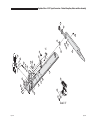
Foldout Ramp - Platform
Below Floor Obstructions ............................... 12
Assembly .................................... 19B, 20B, 21
Auxiliary Power Supply ................................... 13
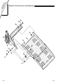
Foldout Ramp - Gear, Motor and Base
Assembly .................................... 22, 23A, 24A
Electronic Control Modules ............................ 14
Foldout Ramp Assembly ............ 23B, 24B, 25
Switch and Component Location ........ 15A, 16A
Kneel Assembly .................................... 26, 27
Wiring Diagrams and Electrical Schematics
Dimensions ...................................................... 28
Wiring Diagram - Power Door, Foldout Ramp
and Kneel System ............................ 15B, 16B
Page 1
SAFETY PRECAUTIONS
Safety Precautions
Maintenance and service procedures must be performed
only by authorized service personnel.
Read this manual,
the conversion's
operator’s manual
and supplements
before performing
operation, maintenance or service
procedures. Failure
to do so may result
in serious bodily
injury and/or property damage.
Perform maintenance and lubrication procedures exactly
as outlined in the Maintenance and Lubrication Schedule
contained in this manual.
Perform troubleshooting and service procedures as outlined
in this manual and/or service bulletins supplied with replacement parts.
Replacement parts must be Braun authorized replacements.
Do not attempt to interface aftermarket control systems
without authorization from The Braun Corporation.
Do not use accessory devices not authorized by The Braun Corporation.
Keep clear of area in which the vehicle kneels (lowers).
Keep clear of area in which ramp operates.
1HYHUPRGLI\DOWHUD%UDXQ&RUSRUDWLRQORZHUHGÁRRUPLQLYDQFRQYHUVLRQ
'RQRWLQVWDOODUDLVHGWRSRQD%UDXQ&RUSRUDWLRQORZHUHGÁRRUPLQLYDQFRQYHUVLRQ
8VHRID%UDXQ&RUSRUDWLRQORZHUHGÁRRUPLQLYDQFRQYHUVLRQ for towing is prohibited.
Failure to follow these safety precautions may result in serious bodily injury and/or
property damage.
Towing
Towing with a Lowered Floor Conversion
8VHRIDORZHUHGÁRRUFRQYHUVLRQYHKLFOHIRU
towing is prohibited.
Transporting a Lowered Floor Conversion
If case of service, The Braun Corporation recomPHQGVWKDWORZHUHGÁRRUFRQYHUVLRQYHKLFOHVEH
transported on a trailer rather than towed with
one set of wheels suspended and the other set
of wheels remaining in road contact.
Page 2
Trailer Transport
MAINTENANCE and SERVICE
Maintenance and Service Requirements
%UDXQORZHUHGÁRRUPLQLYDQ
conversions must be maintained
and serviced by a Braun authorized service representative who
KDVDWWHQGHGDQGEHHQFHUWLÀHG
by The Braun Corporation Sales
and Service School for Braun
Mobility Products.
Read and become familiar with
the operating procedures outlined in the applicable operator’s
manual and the maintenance
and troubleshooting information
contained in this manual before
beginning operation, maintenance or service procedures.
Contact The Braun Corporation
at 1-800-THE LIFT® if any of this
information is not understood.
Electronic Control System:
The electronic control system
provides simple one-touch activation of power functions. For
your convenience, the control
system can be activated using
the OEM remote keyless entry
transmitter or one of the interior
VZLWFKHVLGHQWLÀHGLQWKHRSHUDtor's manual.
Braun Corporation Aftermarket
Control Systems Policy: The
Braun Corporation manufactures
dedicated control systems for its
products. These control systems
have been designed and tested
IRUXVHLQFRQMXQFWLRQZLWKVSHFLÀF
Braun products. Braun control
systems are the only control
systems authorized for use with
Braun products.
Do not attempt to interface aftermarket control systems without
authorization from The Braun
Corporation. To do so may result
in serious bodily injury and/or
property damage.
Page 3
MAINTENANCE and SERVICE
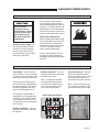
Preventive Maintenance
Maintenance is necessary to ensure safe and trouble free conversion operation. Encourage the
consumer to perform preventive
maintenance procedures. General preventive maintenance consisting of inspections along with
cleaning procedures should be
a part of the consumers routine.
Keeping the passenger slide door
lower track pan free of debris,
ice and snow is one of the most
effective preventive maintenance
practices to exercise. Regular
preventive maintenance procedures will increase the service
life of the conversion, as well as
enhancing safety.
The consumer should inspect and
clean frequently and routinely
(minimum four weeks or 100
cycle intervals).
Note: A Preventive Maintenance
section is provided in the operator's manual.
Maintenance and Lubrication Schedule
Normal vehicle maintenance
must be performed as outlined
in the OEM-supplied owner’s
manual. This maintenance is
not the responsibility of The
Braun Corporation.
The maintenance and lubrication procedures outlined in this
schedule must be performed at
the recommended scheduled
intervals by a Braun authorized
service representative.
&OHDQVSHFLÀHGFRPSRQHQWVDQG
the surrounding area before applying lubricants. When replacing lubricated components, be
sure to lubricate during installation procedures.
$´GULÀOPµVW\OHRIOLJKWRLO
should be applied where Light
Oil is called out (goes on wet
and then dries). Lubricants of
this type are available that do
not attract dust and other debris.
Page 4
Use of improper lubricants can
attract dirt or other contaminants
which could result in wear or
damage to components. Avoid
lubricants that can leave stains.
Some lubricants referenced in the
schedule are available from The
Braun Corporation (part numbers
SURYLGHGZKHUHVSHFLÀHG
All listed inspection, lubrication
and maintenance procedures
VKRXOGEHUHSHDWHGDW´PRQWKµ
intervals following the scheduled
´PRQWKµPDLQWHQDQFH7KHVH
intervals are a general guideline
and will vary according to frequency of use and conditions.
Exposure to severe conditions
(weather, environment, contamination, heavy usage, etc.) may
require inspection and maintenance procedures to be perIRUPHGPRUHRIWHQWKDQVSHFLÀHG
Discontinue use immediately
if maintenance and lubrication
procedures are not properly performed, or if there is any sign of
wear, damage, improper operation or any abnormal condition.
Contact your sales representative or call The Braun Corporation at 1-800-THE LIFT®. One
of our national Product Support
representatives will direct you to
an authorized service technician
who will inspect your conversion.
Maintenance and lubrication procedures
must be performed
DVVSHFLÀHGE\DQ
authorized service
technician. Failure
to do so may result
in serious bodily injury and/or property
damage.
MAINTENANCE and SERVICE
Maintenance and Lubrication Schedule
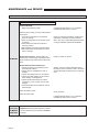
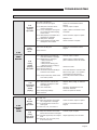
Foldout Ramp: Foldout ramps vary in
design. Disregard references to components
not present.
3 Months
Outboard ramp extension hinge and fasteners
Clean and lubricate with Light Oil. Resecure or
replace fasteners as needed
Inspect ramp inboard pivot points (bolts/screws
and bushings/bearings) for positive securement,
wear or damage
Clean and lubricate with Light Oil. Tighten,
replace or correct as needed
Inspect ramp fold pickup bearing for positive
securement, alignment, wear or other damage
Replace or correct as needed. If bearing
retaining bolt is not secure or is removed for
service, apply Blue #242 Thread Locker Loctite
to retaining bolt and tighten.
Inspect ramp fold arm for positive securement,
alignment, wear or other damage
Tighten, replace or correct as needed
Inspect ramp fold arm bearing slot for excessive
wear or damage
Replace if needed
Inspect ramp extension chain for proper alignment, securement or other defects
Realign, resecure, replace or otherwise correct
as needed
,QVSHFWUDPSÁRRUPRXQWLQJKDUGZDUHIRUVHcurement (loose or missing)
Resecure, replace or correct as needed
General
Lower power slide door track
Inspect for obstructions and clean (vacuum or
blow out debris using compressor)
Center power slide door track
Inspect for obstructions and clean (vacuum or
blow out debris using compressor)
Wheelchair and occupant restraint belts and tie
down track
Inspect for any defects such as cuts, fraying or
any malfunction of belt, buckle or securement
hardware. Clean dirt and debris from tie down
track. Replace immediately if damaged.
Inspect removable seat bases for proper engagement of latching mechanisms
Replace or correct as needed
Page 5
MAINTENANCE and SERVICE
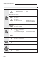
Maintenance and Lubrication Schedule
Perform all procedures listed in previous section also
Power Fold Ramp:
5DPSÁDSH[WHQVLRQFKDLQ
Remove ramp housing cover/rear vertical panel
and inspect:
7RSPRXQWEUDFNHWEROWVIRUVHFXUHPHQW
(loose or missing)
0RWRUPRXQWLQJEROWVIRUVHFXUHPHQWORRVH
or missing)
5DPSIROGDUPVHFXUHPHQWFROODUDQG
mounting screws)
0LFURVZLWFKHVVHFXUHPHQWDQGDGMXVWPHQW
0LFURVZLWFKZLUHVDQGWHUPLQDOVIRUVHFXUHment or damage
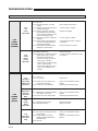
6 Months
Inspect power source: Vehicle battery, 50
ampere fuse, vehicle engine compartment fuse
block and driver side under dash-mounted fuse
block.
Inspect kneel actuator assembly for:
$FWXDWRUPRXQWLQJSLQVHFXUHPHQWPLFURswitch activation block)
,QVSHFWFKDLQIRUPLVDOLJQPHQWZHDURU
damage
,QVSHFWFKDLQPDVWHUOLQNVIRUVHFXUHPHQW
,QVSHFWFKDLQLGOHUSXOOH\IRUVHFXUHPHQW
wear, damage or misalignment
,QVSHFWHOHFWULFDOKDUQHVVHVIRUSRVLWLYH
connections, proper routing, wear or other
damage
.QHHOPLFURVZLWFKHVVHFXUHPHQWZHDURU
other damage
Lubricate with Anti-Seize (14 oz. caulk tube
available per Braun part no. 24710)
Resecure, adjust microswitches, replace damaged parts or otherwise correct as needed.
Note: See 2011 Foldout Ramp Exploded views
on pages 19B-20B, 23A-24A and 23B-24B.
Resecure, repair or replace
Realign, resecure, replace damaged parts or
otherwise correct as needed. Note: See Kneel
Actuator Assembly exploded view on pages 26
& 27.
Kneel electrical override
Check operation
Kneel assembly chain
Lubricate with Anti-Seize (14 oz. caulk tube
available per Braun part no. 24710)
Consecutive
3 Month
Intervals
Page 6
Repeat all previously listed inspection, lubrication and maintenance procedures at 3 month
intervals.
TROUBLESHOOTING
Troubleshooting Diagnosis Chart
Troubleshooting and
repair procedures
must be performed
DVVSHFLÀHGE\DQ
authorized service
technician only. Failure to do so may result in serious bodily
injury and/or property
damage.
FUNCTION
The cause of the problem can
be determined by locating the
function and related symptom in
the Troubleshooting Diagnosis
SYMPTOM
1.10
No Power to
Conversion
Systems
(Circuit Problem)
1.00
NO
OPERATION
Operation should be discontinued
immediately if a conversion problem occurs. Repairs should not
be attempted by the consumer.
Contact the sales representative
or call The Braun Corporation at
1-800-THE LIFT®. One of our
national Product Support representatives will direct you to an
authorized service technician who
will inspect your vehicle.
1.20
Power to
Conversion
Systems
But No
Operation
POSSIBLE CAUSE
&KDUWV7KHVSHFLÀFFDXVHDQG
remedy can then be determined
by process of elimination. Electrical Schematics and Wiring
Diagrams are provided to aid in
troubleshooting.
A Repair Parts section with exploded views and corresponding
parts lists is also provided. Correct the problem if possible. If the
problem continues, contact The
Braun Corporation.
REMEDY
1.11
1.12
1.13
1.14
1.15
Poor ground connection
Battery terminals dirty
Battery damaged
Battery discharged
12 volt source (check fuses for
12 volts)
1.16 Circuit breaker tripped or
damaged
Clean and tighten
Clean and tighten
Replace
Charge battery
Check for blown fuse, loose terminals
or broken wire or cable
Reset or replace
1.21 Transmission not in Park
1.22 OEM power sliding door main
switch in OFF position
1.23 Power slide door locked
1.24 Slide door handles have been
manually operated
1.25 Loose connection
1.26 Broken wire
1.27 Wire terminal
1.28 Control switch damaged
1.29 OEM keyless transmitter (FOB)
does not function properly or
damaged
1.30 Braun electronic controller
Engage transmission in Park
Press switch to ON position
Unlock door
Press a control switch
Clean and tighten
Repair or replace
Crimp tightly to wire
Replace
Relocate to avoid interference, replace
battery or replace transmitter. See
OEM owner's manual.
Press main electronic controller reset
button and try operation again. If no
operation - run serial diagnostics test.
If no operation - contact Braun Product
Support.
Page 7
TROUBLESHOOTING
FUNCTION
SYMPTOM
2.10
No
Lower
Operation
2.00
KNEEL
SYSTEM
(LOWER)
2.20
Faulty
Kneel
(Lower)
Operation
Page 8
2.11 See 1.00
2.12 Kneel On/Off switch is in OFF
position.
2.13 Actuator harness disconnected or
otherwise damaged
2.14 Actuator damaged. Press the
kneel electrical override switch
to test actuator (located on ramp
motor cover/interior panel).
2.15 Chain disconnected or otherwise
damaged
2.16 Kneel Lowered microswitch harness disconnected/damaged or
microswitch damaged
2.17 Kneel electrical override switch
damaged or disconnected
2.21 Mechanical binding
2.22 Misalignment or damage to kneel
system components. Inspect
kneel actuator assembly for:
$FWXDWRUPRXQWLQJSLQVHFXUHment (loose or missing)
,QVSHFWFKDLQIRUZHDUPLVDOLJQment, or other damage
,QVSHFWFKDLQSXOOH\IRUVHFXUHment, wear, misalignment or
damage
REMEDY
Press switch to ON position
Connect, repair or replace
Replace if damaged.
Connect, repair or replace
Connect/repair harness or replace
microswitch
Check connection or replace
Check and correct
Connect, replace or otherwise correct
as needed
3.11 See 1.00
3.12 Doors locked
Unlock doors
3.13 Power door motor harness disconnected or damaged
3.14 Power door motor damaged
Correct or contact Braun Product
Support
Contact Toyota Service Center
3.21 Misaligned or otherwise damaged
drive cable or door track
3.22 Power door motor clutch failure
Correct or contact Braun Product
Support
Contact Toyota Service Center
3.30
Faulty
Open
Operation
3.31 Obstruction in door path
3.32 Mechanical binding
Remove obstruction
Check and correct
3.40
Door Does
Not Open
Fully
3.41 Door doesn't catch full open position hold latch
3.42 Power sliding door module
(PSDM) needs recalibrated for
extended travel
3.43 See 3.30
Correct or contact Braun Product
Support
Correct or contact Braun Product
Support
3.10
No Open
Operation
(Motor Does
Not Run)
3.00
POWER
DOOR
(OPEN)
POSSIBLE CAUSE
3.20
Motor Runs
But Door
Does Not
Move
TROUBLESHOOTING
FUNCTION
SYMPTOM
POSSIBLE CAUSE
4.11 See 1.00 and 3.41
4.12 No door full open signal
4.10
No Unfold
(Deploy)
Operation
4.00
FOLDOUT
RAMP
DEPLOY
4.20
Ramp
Contacts
Door
4.30
Faulty
Unfold
(Deploy)
Operation
4.13 Ramp motor harness disconnected or damaged
4.14 Loose, damaged or missing fold
arm securement collar/coupling
and/or screws
4.15 Ramp Deploy microswitch out of
adjustment or damaged
4.16 Ramp motor damaged
4.17 Ramp electrical override switch
damaged or disconnected
4.21 Door not fully open
5.00
FOLDOUT
RAMP
STOW
Correct or contact Braun Product
Support
Connect, repair or replace
Tighten, replace or otherwise correct
as needed
Check connection, adjust or replace.
Replace motor
Check connection or replace.
Correct or contact Braun Product
Support
4.22 See 3.41
4.31 Ramp Deploy microswitch harness disconnected or damaged
4.32 Misalignment or damage to:
5DPSIROGEHDULQJ
5DPSIROGDUP
5DPSIROGDUPEHDULQJVORW
5DPSSLYRWSRLQWVRUKLQJHV
4.33 Mechanical binding
4.34 See 3.41 and 4.15
4.35 Obstruction detected resulting in
excessive motor current
4.36 Ramp module ramp select switch
VHWWRLQÁRRUSRVLWLRQ
4.40
Faulty Ramp
Extension
Unfold
(Deploy)
REMEDY
4.41 Ramp extension chain broken,
detached, misaligned or otherwise damaged
4.42 Lack of lubrication
4.43 Ramp hinge damage
4.44 See 4.35
5.10
No Fold
(Stow)
Operation
5.11 See 1.00
5.12 Ramp Stow Position microswitch
out of adjustment or damaged
5.13 Controller doesn't receive door
close signal
5.14 See 4.13, 4.14, 4.16 and 4.17
5.20
Faulty
Fold (Stow)
Operation
5.21 Ramp Stow Position microswitch
harness disconnected or damaged
5.22 Fold arm support/stop out of adjustment
5.23 See 3.41, 4.13, 4.14, 4.32, 4.33,
4.35, 4.42 and 4.43
Connect, repair or replace
Realign, tighten, replace damaged
parts or otherwise correct as needed
Check and correct
Press main electronic controller reset
button and try again. If no operation contact Braun Product Support.
Press ramp select switch to foldout
position
Replace, attach, realign or otherwise
correct
Lubricate - See Maintenance and
Lubrication Schedule
Correct or replace as needed
Check connection, adjust or replace.
Correct or contact Braun Product
Support
Connect, repair or replace
Adjust support/stop for more travel
Page 9
TROUBLESHOOTING
FUNCTION
SYMPTOM
6.10
No
Close
Operation
POSSIBLE CAUSE
6.11 See 3.10, 4.12 and 5.12
6.12 Power slide door module (PSDM)
did not see stowed signal
REMEDY
Correct or contact Braun Product
Support
6.20
Motor Runs - Door
Does Not Move
6.00
POWER
DOOR
(CLOSE)
6.30
Faulty
Operation
6.40
Door Does
Not Close
Fully (Door
Kickback)
6.50
Door Contacts
Ramp When
Closing
7.10
7.00
KNEEL
SYSTEM
(RAISE)
6.21 See 3.20
No Raise
Operation
6.31 See 3.30
6.41 See 3.30
6.42 Ramp obstructing door
6.51 Ramp Stow Position microswitch
out of adjustment
6.52 See 4.40, 5.12 and 5.20
7.11 See 1.00, 2.12, 2.13, 2.14, 2.15
and 2.17
7.12 Kneel Raised microswitch harness disconnected/damaged or
microswitch damaged
7.20
Faulty
Operation
8.00
KNEEL
ELECTRICAL
OVERRIDE
(RAISE)
9.00
RAMP
ELECTRICAL
OVERRIDE
(STOW)
Page 10
8.10
No Operation
8.20
Faulty
Operation
9.10
No Operation
9.20
Faulty
Operation
7.21 See 2.20
8.11 See 1.10, 2.13, 2.14, 2.15 and
2.17
8.21 See 2.20
9.11 See 1.10, 4.13, 4.14 and 4.16
9.21 See 4.13, 4.32, 4.33, 4.41, 4.42
and 4.43
Adjust ramp Stow Position microswitch inward (toward cabin area)
Adjust Ramp Stow Position microswitch inward (toward cabin area)
Connect/repair harness or replace
microswitch
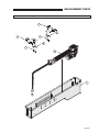
MICROSWITCHES
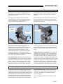
Ramp Microswitch Adjustment
The ramp motor assembly is equipped with two
microswitches, the deploy microswitch and stow
position microswitch.
The stow position microswitch determines the full
stow position (how far the ramp stows inside the
vehicle).
The deploy microswitch cuts the ramp motor
when the platform reaches a position where the
ramp will complete the deploy function by the
force of gravity (ramp to ground level).
Remove the ramp motor assembly interior cover to
access microswitches (located rear of the passenger slide door). Note: It is not necessary to remove
any other interior panels.
Stow Position
Microswitch
Slider
Assembly
Adjustment
Screw
Deploy
Microswitch
Cam
Ram
p
Stow Position Microswitch Adjustment: An
adjustment screw moves the position of the stow
position slider assembly inward and outward.
Turn the screw clockwise to adjust the ramp
stowed position inward. Turn the screw counterclockwise to adjust the ramp position outward.
Ensure the ramp does not obstruct the power slide
door (check per following procedure).
Door Obstruction: Manually open the slide door
fully. Move the top of the ramp out slightly until the
ramp enters the path of the door. Press a control
switch. Caution: Observe and stop door if ramp
does not stow fully to avoid damage. If the ramp
stows fully and the door closes, the microswitch
is adjusted properly. If the door contacts the ramp,
the stow microswitch needs to be adjusted inward.
Adjust microswitch slider slightly and repeat procedures.
Deploy Microswitch Adjustment: The deploy microswitch is cam activated. The microswitch is secured with two mounting screws. The microswitch
can slide in a rotary motion to change it's position
is relation to the cam. The deploy microswitch cuts
power to the ramp motor, allowing the ramp to gravity down and complete the deploy function. Adjust
the switch to allow gravity to complete the deploy
operation. Ensure the ramp motor shuts off before
the ramp reaches the horizontal position or below.
Kneel Microswitches
7KHDFWXDWRUDVVHPEO\LVHTXLSSHGZLWKWZRÀ[HG
position microswitches (not adjustable). A bracket
(vertical tab) at the end of the actuator shaft trips the
microswitches as the shaft extends and retracts. If
the kneel switches are not activated (tripped), the
kneel actuator will clutch (ratchet) continuously for
approximately 10 seconds at end of actuator travel.
Kneel Actuator Access: Remove the kneel asVHPEO\FRYHURQWKHYHKLFOHÁRRUXQGHUWKHWKLUG
row seats. See Below Floor Obstructions Diagram on page 12.
Note: Changing the kneel chain length is prohibited.
Page 11
BELOW FLOOR OBSTRUCTIONS
2011 Toyota Lowered Floor Minivan Conversion - Foldout Ramp
When installing an
electrical tie-down,
power seat or other
auxiliary device, obstructions below the
ÁRRUPXVWEHDYRLGHG
Obstructions include
wiring, fuel system,
brake lines, etc. Installers must be aware
of these obstructions.
Refer to this illustration when installing
aftermarket equipment
to avoid contacting or
damaging vital compoQHQWVXQGHUWKHÁRRU
Drilling or cutting into
such obstructions
may result in potential
hazards as well as
property damage.
Note: Some wiring
harnesses shown may
not be present. Avoid
all harness locations.
Color Key
Battery
OEM Wiring
Battery
Power Fuse
Braun Wiring
Brake System
Heat & A/C
Fuel Return
Line
OCS & ORIS
Modules
Main Fuel
Line
Fuse Block
& SRS Module
Assembly
Brake
Lines
Seat Connector
(Driver &
Passenger)
Rear Heat
Lines
Emergency
Brake Cable
Rear AC
Lines
Fuel Vent
Line
SRS Crash
Sensor (Driver
& Passenger)
Fuel Vapor
Line
Fuel Fill
Tube
Check for obstructions such as wires,
gas lines, exhaust,
etc. before drilling
or cutting through
ÁRRU)DLOXUHWRGRVR
may result in serious
bodily injury and/or
property damage.
Page 12
Fuel System
Fuel Tank
Braun
Controller
Kneel
System
Charcoal
Canister
AUXILIARY POWER SUPPLY
Fuse Blocks: Two fuse blocks
are provided for use as an auxiliary power source (one ignition fuse
block and one battery fuse block).
The battery fuse block provides
power at all times (independent of
the vehicle ignition). The ignition
fuse block supplies power only
when the vehicle ignition is on.
Note: If installing an auxiliary
electrical device that requires
more than a 40 ampere power
source, an alternative power
source must be provided.
Fuse Block Access: The fuse
blocks are located at the bottom of the center console. Fuse
block access procedures are
provided in the service manual.
Note: The fuse blocks are part
of an electrical assembly. Two
ground studs are also provided.
Under Dash Fuse Blocks
F4
OPEN
F2
F3
OPEN
OPEN
30
F1
F1
F2
F3
F4
OPEN
OPEN
OPEN
30
OPEN
3
Ignition Fuse Block: The total
maximum load must not exceed
30 amperes.
Battery Fuse Block: The total
maximum load must not exceed
40 amperes per fuse.
OPEN
The installer is responsible for
supplying the correct gauge wire
and fuse for the particular device
to be attached to the fuse block
DVVSHFLÀHGE\WKHPDQXIDFWXUHU
of the device).
Refer to the illustration on previous page to avoid contacting or
damaging vital components under
WKHÁRRU
5LVNRIHOHFWULFDOÀUH
Install and electrically
terminate auxiliary
electrical device as
VSHFLÀHGE\GHYLFH
manufacturer.
29429
Auxiliary Power Supply: Do
not connect auxiliary devices
directly to the vehicle battery.
Doing so may result in damage to electrical system and/or
electronic components.
Below Floor Obstructions:
When installing aftermarket equipPHQWREVWUXFWLRQVEHORZWKHÁRRU
must be avoided. Obstructions
include wiring, fuel system, brake
lines, etc. Installers must be
aware of these obstructions.
29428
Do not connect
auxiliary devices to
vehicle battery. Doing
so may result in damage to electrical system and/or electronic
components.
Two fuse blocks are provided
as an auxiliary power source for
dealer-installed auxiliary electrical
device(s). Fuse block details and
VSHFLÀFDWLRQVDUHSURYLGHGEHORZ
The fuse blocks are located in the
bottom of the center dash console.
Page 13
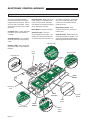
ELECTRONIC CONTROL MODULES
Diagram - Electronic Control Module Connections / Inputs / Indicators
The control module assembly is
mounted to the bottom of the passenger side third row seat. Removal of this seat is prohibited. Tip the
seat forward to access the module
assembly.
Kneel Override - Buttons drive the
kneel system in the direction indicated. The kneel LED will illuminate Red when kneeling and Green
when unkneeling (raising).
trol switch is activated). A tone will
also sound if the ramp motor pulls
current over the controller preset
baseline current.
Ramp Select Switch - Sets
FRQWUROOHUIXQFWLRQVWRDQLQÁRRURU
foldout ramp.
Reset Button - Resets controller.
Computer Port - Laptop diagnostic
connection port to the electronic
controller.
Grounding Studs - The controller
assembly provides two grounding
studs.
Speaker Enable - Turns the
internal speaker On and Off. The
speaker sounds a tone whenever
an operate signal is seen (any con-
Ramp Override - Buttons drive the
ramp in the direction indicated. The
ramp LED will illuminate Red when
deploying and Green when stowing.
Indicator LEDs
Indicator LEDs - LED's illuminate
whenever a switch is grounded (as
labeled).
Fuse
Block
Kneel Override
Computer Port
TM
m
®
te
W
O
E
ID
RR
VE
LO
A
NU
MA
H
-T
0
0
LL
O
VE
RR
ID
E
1
-8
M
AN
UA
L
SN
R
WN
E
DO
E
LIF
Pa T ®
te
nt w
#6 ww
,8 .b
25 ra
,6 u
28 n
B2 ab
il
it
y.
co
m
TM
A BR
CC A
ES UN
S ®
10 OR K
02 Y NE
81 MO EL
-0 D
02 UL
E
P
U
Pa
N
.co
ity
bil
na
au 2
br 8 B
w. ,62
w
w ,825
#6
nt
D
Grounding
Stud
34
85
8
0
R
-0
B
8
V
8
E
1
R
0
SN
SW
0
TM
1
®
B
2
a
b
ilit
y.c
o
m
K
O
D
0
0
-T
H
E
IN
IN 5
IN 6
IN 7
8
H
-T
-8
1
34
(2 45
01 1
0)
TM
m
o
y.c
il
it
O
V
E
R
R
ID
E
E
L
IF
Pa T ®
te
n
t w
# w
6
,8 w
2 .b
5 r
,6 a
2 u
8 n
B ab
2
OY
34703
35
97
0
PL
0
M
A
N
U
A
L
DE
0
ST
OW
-8
T
SE
RE
1
O
S N
OF PEA
KE
F
R
N
K EE
N
K EE L F
N L U
E F L
E
L
O L E UL D
R N L O
LIF
FU A U W
Pa T
te
LL BL P N
nt w
#6 w
O E
,8 w.b
P
25
E
,6 ra
N
28 un
IN
1
OP
IN
IN
ER
3
4 C
AT
WA
IN
ID ON
E
EN TR
KE
9
ST
TIF OL
UP
OW
IE LE
R
R
C BR
C A
E U
S
1 SO N ®
0 R R
0 Y A
2 M M
7
8 O P
-0 D
0 U
2 L
E
OY
PL
A
AJ
DE
SN
AR
OR
10
W
Speaker
Enable
O
ST
Y
O
PL
DE
Ramp Override
Ramp
Module
CT
LE
SE
P
H
M
RA WITC OUT
S
LD
Reset
Button
FO
L
INF
Page 14
DO
E
ID
RR
VE
LO
UA
N
MA
w
IN
Main
Controller
TM
w
11
OR
om
®
IN
LO
c
y.
r
PA
RK
INF
ilit
.b
w
12
CT
LE
SE
MP CH
RA WIT LDOUT
S
FO
ab
n
au
IN
A
1
U
N®
C
O
N
TR
O
UP
Grounding
Stud
Kneel
Module
OO
R
Ramp
Select
Switch
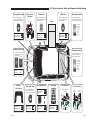
2011 Toyota Conversion - Switch and Component Location Diagram
Fuse Block
30
OPEN
OPEN
F1
F2
F3
F4
30
F2
F1
F3
F4
29428
B-Pillar Switch
C-Pillar Switch
Kneel Override Switch
A switch is located on the wall
panel ahead of the passenger
slide door (B-Pillar).
A switch is located on the wall
panel rear of the passenger
slide door (C-Pillar).
The kneel override switch is
located rear of the ramp in the
lower wall panel (bottom switch).
Ramp
OPEN
OPEN
OPEN
OPEN
Press and
hold this
switch to
release
kneel
(raise
vehicle).
Press and hold
switch displaying
slide door graphic.
Press and release
switch displaying
slide door graphic.
Press and hold
switch displaying
slide door graphic.
PWR
DOOR
Sliding Door Main Switch
Ramp Override Switch
The sliding door main switch
is located on the driver lower
left knee bolster.
The ramp override switch is
located rear of the ramp in the
lower wall panel (top switch).
((orange)
g )
OUT: Power
Functions
Enabled
Rear Fuse Block
Battery Power Rear
Fuse Block
Ramp
Module
Kneel
Module
F3
20
Page 15A
OFF
SW REV
Controller Assembly
SN
TM
UP
MANUAL OVERRIDE
DOWN
IN 3 WAKEUP
1-800-THE LIFT ® www.braunability.com
Patent #6,825,628 B2
IN 12 PARK
IN 11 DOOR AJAR
TM
SN
IN 1 OPERATE
1-800-THE LIFT ® www.braunability.com
Patent #6,825,628 B2
34451
(2010)
ON
SPEAKER
OFF
DEPLOY
35970
KNEEL FULL DOWN
KNEEL FULL UP
KNEEL ENABLE
DOOR FULL OPEN
CONTROLLER
IDENTIFIER
TM
MANUAL OVERRIDE
DOWN
UP
MANUAL OVERRIDE
34858
IN 5
IN 6
IN 7
IN 8
RESET
1-800-THE LIFT ® www.braunability.com
Patent #6,825,628 B2
TM
BRAUN® KNEEL
ACCESSORY MODULE
100281-002
100188-001
SN
1-800-THE LIFT ® www.braunability.com
Patent #6,825,628 B2
IN 12 PARK
IN 11 DOOR AJAR
IN 1 OPERATE
IN 3 WAKEUP
CONTROLLER
IDENTIFIER
IN 10 DEPLOY
Press and hold
switch displaying
slide door graphic.
TM
IN 9 STOW
Press switch to OFF
position to disable
kneel system.
STOW
Press and hold
switch displaying
slide door graphic.
DEPLOY
Press and release
switch displaying
slide door graphic.
34451
(2010)
ON
SPEAKER
OFF
1-800-THE LIFT ® www.braunability.com
Patent #6,825,628 B2
MANUAL OVERRIDE
35970
BRAUN® RAMP
ACCESSORY MODULE
100278-002
SN
SN
IN 4
TM
KNEEL FULL DOWN
KNEEL FULL UP
KNEEL ENABLE
DOOR FULL OPEN
STOW
SW REV
IN 5
IN 6
IN 7
IN 8
RESET
1-800-THE LIFT ® www.braunability.com
Patent #6,825,628 B2
BRAUN® CONTROLLER
BRAUN® KNEEL
ACCESSORY MODULE
100281-002
100188-001
SN
IN 10 DEPLOY
25
OPEN
20
BRAUN® CONTROLLER
BRAUN® RAMP
ACCESSORY MODULE
100278-002
IN 9 STOW
25
3
F3
F6
F6
F2
F2
F5
F5
F1
F1
F4
F4
25
ON
Controller Assembly
25
Press switch to ON
position to enable
kneel system.
Keyless Entry
OPEN
For front seat passengers, a
switch is located to the left of
the center console (dashboard).
Kneel On/Off Switch
3
Driver Dash Switch
20
Overhead
Console Switch
20
IN: Power
Functions
Disabled
Release
the switch
when the
ramp is
fully
stowed
(stops).
IN 4
For front seat passengers, a
switch is located to the right of
the center console (dashboard).
Center Console
Fuse Block
29429
Passenger Dash Switch
34858
SmartBox Controller
Page 16A
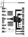
Sw
Lo itch Un
ca & fol
ti C d
on o fo
D mp r:
ia o
gr ne
am n
t
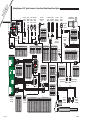
Wiring Diagram - 2011 Toyota Conversion - Power Door, Foldout Ramp & Kneel System
NOT USED
-
2
WH/BK 20G
DFO Ground
3
WH/VT 20G
DFO Signal
2-COND WIRE CODE
RD 22G
BK 22G
FUNCTION
COLOR
1
DK BL 20G
DK BL 20G
OR 20G
YL 14G
3-COND WIRE CODE
PIN
Ramp Motor &
Gear Box 36087A
C-Pillar
Switch
34454
Microswitch
Stow
33421A
DK BL 20G
WH 20G
PK 20G
VT 20G
DK BL 20G
DK BL 20G
29428
OPEN
OPEN
3
OPEN
30
E91074A
WH/BK 20G (COM)
WH/VT 20G (NO)
F4
RD 22G
BK 22G
F2
F3
F4
TO OEM
Pass Door
Ajar (Body)
TO OEM TO OEM
Door
Door Body
Harness Harness
ON
RD 22G
BK 22G
F1
F3
WH/BK 20G
DK BL 20G
RD 12G
OPEN
F2
F1
Door Full
Open Switch
36113
Driver Passenger
Dash
Dash
Switch
Switch
34454
34454
OFF
29429
OPEN
30
OPEN
To Battery
YL 14G
TO Console Kneel
Power
ON/OFF
Outlet
Switch
31022
DK BL 20G
WH 20G
PK 20G
VT 20G
RD 12G
DK BL 20G
WH/BK 20G
RD 12G
FUNCTION
PIN
COLOR
1
WH/RD/OR 14G
Ramp Motor
2
OR/BK 14G
Ramp Motor
YELLOW
Driver
A-Pillar
Ground
E91086A
3-COND WIRE CODE
TO Console
Power
Outlet
PIN
E91036A
FUNCTION
COLOR
1
WH/OR 20G
DFO Power
2
WH/BK 20G (2)
DFO Ground
3
WH/VT 20G
DFO Signal
RD 12G
E91037A
PIN
Microswitch
Deploy
34806
TO OEM
Pass Door
Ajar (Switch)
WH/BK 20G
50 AMP
FUSE
2-COND WIRE CODE
DK BL 20G
FUNCTION
COLOR
1
BK (Motor)
Ramp Motor
2
RD (Motor)
Ramp Motor
WH 20G
WH/BK 20G
BK 20G
WH/BK 20G
12-COND WIRE CODE
4-COND WIRE CODE
FUNCTION
PIN
COLOR
FUNCTION
PIN
COLOR
FUNCTION
PIN
COLOR
FUNCTION
PIN
COLOR
FUNCTION
PIN
1
OR/BK 14G
Ramp Motor
8
WH/RD/OR 14G
Ramp Motor
1
RD 22G
Dash & B-Pillar
1
VT & RD
Dash & B-Pillar
1
NOT USED
-
1
NOT USED
2
WH/BK 20G
Ramp Switch COM
9
BK 20G
Ramp Deployed
2
BK 22G
Ground
2
WH/BK & BK
Ground
2
NOT USED
-
2
NOT USED
-
NOT USED
-
3
NOT USED
-
3
DK BL 20G (2)
CAN H
3
DK BL 20G
CAN H
OR 20G
Kneel On/Off
4
OR 20G
Kneel On/Off
4
DK BL 20G
CAN H
4
DK BL 20G
CAN H
WH 20G (2)
CAN L
5
WH 20G
CAN L
PIN
COLOR
Door Full Open
10
WH 20G
Ramp Stowed
WH/OR 20G
Door Full Open PWR
11
NOT USED
-
4
5
NOT USED
-
12
NOT USED
-
5
6
NOT USED
-
13
NOT USED
-
6
WH 20G
CAN L
6
WH 20G
CAN L
Ramp Motor GRD
7
PK 20G
Door Enable
7
PK 20G
Door Enable
14
BK 14G
RD 20G
RD/WH 14G
GY/RD 20G
8
8
DK BL 20G
Controller Operate
10
LT GN 20G
Park Signal
11
DK BL 20G
Door Ajar
IN 10 DEPLOY
IN 11 DOOR AJAR
BRAUN® CONTROLLER
100188-001
SN
SW REV
IN 9 STOW
NOT USED
RD 20G
WH/BK 20G
WH/BK 20G
LT BL 20G
DK BL 20G
LT GN 20G
DK BL 20G
Door Enable
6
PK 20G
Door Enable
7
GY/RD 20G
TIG Power
8
LT BL 20G
Wake Up
9
DK BL 20G
Controller Operate
10
LT GN 20G
Park Signal Out
11
WH 20G
CAN L
12
DK BL 20G
CAN H
34858
E91033A
PK 20G
-
9
NOT USED
-
-
10
NOT USED
-
11
VT 20G (2)
Door Operate In
11
VT 20G
Door Operate In
12
VT/YL 20G
Door Operate Out
12
VT 20G
Door Operate Out
6-COND WIRE CODE
COLOR
FUNCTION
PIN
COLOR
1
WH/RD/OR 14G
Ramp Motor
1
WH/RD/OR 14G
Ramp Motor
2
OR/BK 14G
Ramp Motor
2
OR/BK 14G
Ramp Motor
BK 20G
Ramp Deployed
WH 20G
Ramp Stowed
3
Door Enable
NOT USED
NOT USED
4-COND WIRE CODE
5-COND WIRE CODE
Ramp Deployed
3
4
WH 20G
Ramp Stowed
4
5
WH/BK 20G
Ramp Switch COM
5
6
NOT USED
-
6
BK 20G
8-COND WIRE CODE
PIN
COLOR
FUNCTION
PIN
COLOR
FUNCTION
1
OR/RD 14G
Kneel Override PWR
1
BL/BK 14G
Kneel Motor
PIN
2
RD/WH 14G
Ramp Override PWR
2
WH 14G
Kneel Motor
1
3
BK 12G
Ground
3
BN/WH 20G
Kneel Raised
2
4
RD 12G
Controller PWR
4
WH/BK 20G
Kneel Switch COM
3
Kneel Lowered
4
5
TN/WH 20G
5
4-COND WIRE CODE
RD 12G
GY/RD 20G
LT BL 20G
DK BL 20G
LT GN 20G
8
Door Enable
6-COND WIRE CODE
PIN
FUNCTION
WH/BK 20G (2) Ramp Switch COM
NOT USED
-
E91035A
RD/WH 14G
OR/RD 14G
IN 12 PARK
SN
BRAUN® KNEEL
ACCESSORY MODULE
100281-002
MANUAL OVERRIDE
1-800-THE LIFT ® www.braunability.comTM
Patent #6,825,628 B2
UP
Controller
Fuse Block
Wake UP
Door Operate Out
PK 20G
Gateway Module
LT BL 20G
VT 20G
5
20
3
6
4
25
Controller Identifer
Operate In
25
WH/BK 20G
Ground
VT 20G
RD/WH 14G
5
BK 14G
GY/RD 20G
RD/WH 14G
Controller GRD
Ramp Stowed
WH/BK 20G
3
F3
WH/BK 20G
WH 20G
2
F6
4
1
F2
Controller PWR
F5
KNEEL FULL DOWN
KNEEL FULL UP
KNEEL ENABLE
DOOR FULL OPEN
CONTROLLER
IDENTIFIER
FUNCTION
RD 20G
F1
IN 5
IN 6
IN 7
IN 8
1-800-THE LIFT ® www.braunability.comTM
Patent #6,825,628 B2
IN 4
COLOR
3
FUNCTION
F4
34451
(2010)
IN 3 WAKEUP
PIN
COLOR
3
BRAUN® RAMP
ACCESSORY MODULE
100278-002
SN
MANUAL OVERRIDE
1-800-THE LIFT ® www.braunability.comTM
Patent #6,825,628 B2
12-COND WIRE CODE
PIN
20
35970
RD 20G
RD/WH 14G
GY/RD 20G
RD/WH 14G
RD/WH 14G
BK 14G
PK 20G
9
10
PIN
5-COND WIRE CODE
FUNCTION
COLOR
1
OR/RD 14G
Kneel Override PWR
PIN
COLOR
FUNCTION
2
RD/WH 14G
Ramp Override PWR
1
BL/BK 14G
Kneel Motor
3
BK 12G
Ground
2
4
RD 12G
Controller PWR
3
4
5
E91032A
OR/RD 14G
RD/WH 14G
BK 14G
RD 12G
RD/WH 14G
OR/RD 14G
RD 12G
BK 14G
WH 14G
Kneel Motor
BN/WH 20G
Kneel Raised
WH/BK 20G (2) Kneel Switch COM
TN/WH 20G
Kneel Lowered
2-COND WIRE CODE
PIN
COLOR
FUNCTION
1
WH 14G
Kneel Motor
2
BL/BK 14G
Kneel Motor
RD/WH 14G
BK 14G
E91094A
Ramp Motor PWR
RD/WH 14G
1, 2, 7, 9 & 12-24
IN 1 OPERATE
C-Pilliar
Ground
WH/VT 20G
4
24-COND WIRE CODE
ON
SPEAKER
OFF
-
3
STOW
RESET
FUNCTION
COLOR
3
7
DEPLOY
12-COND WIRE CODE
E60208A
4-COND WIRE CODE
14-COND WIRE CODE
8-COND WIRE CODE
FUNCTION
PIN
COLOR
FUNCTION
BK 14G
Ground
1
BK 14G
Ground
BL/BK 14G
Actuator 2
2
WH/RD/OR 14G
BL/BK 14G
Kneel Motor 2
3
WH/RD/OR 14G Ramp Motor 1
OR/RD 14G
Kneel Override PWR
4
RD/WH 14G
COLOR
Motor
Ramp Override PWR
WH 14G
Actuator 1
5
OR/BK 14G
Motor
6
WH 14G
Kneel Motor 1
6
OR/BK 14G
Ramp Motor 2
7
NOT USED
-
7
NOT USED
-
8
NOT USED
-
8
NOT USED
-
Kneel Override
Switch 33469
WH/BK (COM)
BN/WH (NO)
WH/BK (COM)
TN/WH (NO)
Ramp Override
Switch 33469
WH/BK (COM)
BN/WH (NO)
2-COND WIRE CODE
PIN
DOWN
BK 12G
BK 12G
COLOR
FUNCTION
1
BK (Motor)
Kneel Motor
2
RD (Motor)
Kneel Motor
14-COND WIRE CODE
SmartBox
Controller
Assembly
Page 15B
PIN
COLOR
FUNCTION
1
RD/WH 14G
Battery FS4
2
NOT USED
-
3
NOT USED
-
4
NOT USED
-
5
WH/BK 20G
Switch Common
24-COND WIRE CODE - E91033A
Controller
Bracket
Ground
PIN
1
2
COLOR
FUNCTION
PIN
COLOR
NOT USED
-
13
14
WH/BK 20G (2) Controller GRD
3
NOT USED
24-COND WIRE CODE - E91033A
FUNCTION
PIN
FUNCTION
PIN
COLOR
DK BL 20G
Door Ajar
1
WH 14G
Kneel Motor 1
2
NOT USED
-
13
DK BL 20G
Door Ajar
WH/BK 20G
Controller GRD
14
WH 14G
Kneel Motor 1
NOT USED
COLOR
FUNCTION
-
15
Kneel Motor 2
3
-
15
6
NOT USED
-
4
OR 20G
Kneel Enable
16
WH 20G (2)
Ramp Stowed
4
OR 20G
Kneel Enable
16
WH 20G
Ramp Stowed
7
BL/BK 14G
Kneel Motor 2
5
VT 20G
B-Pillar Switch
17
WH/BK 20G
Ramp Switch COM
5
VT 20G
B-Pillar Switch
17
WH/BK 20G
Ramp Switch COM
8
BK 14G
Ground
6
VT 20G
Door Operate Out
18
BK 20G
Ramp Deployed
6
VT/YL 20G
Door Operate Out
18
BK 20G
Ramp Deployed
BL/BK 14G
BL/BK 14G
Kneel Motor 2
9
TN/WH 20G
Kneel Lowered
7
-
19
PK 20G
Door Enable
7
-
19
PK 20G
Door Enable
10
BN/WH 20G
Kneel Raised
8
BN/WH 20G
Kneel Raised
20
PK 20G
Door Enable
8
BN/WH 20G
Kneel Raised
20
PK 20G
Door Enable
11
OR 20G
Kneel On/Off
9
WH/BK 20G
Kneel Switch COM
21
WH/RD/OR 14G
Ramp Motor
9
WH/BK 20G
Kneel Switch COM
21
WH/RD/OR 14G
Ramp Motor
12
NOT USED
-
10
TN/WH 20G
Kneel Lowered
22
OR/BK 14G
Ramp Motor
10
TN/WH 20G
Kneel Lowered
22
OR/BK 14G
Ramp Motor
13
NOT USED
-
11
DK BL 20G
CAN H
23
11
DK BL 20G
CAN H
23
14
WH 14G
Kneel Motor 1
12
WH 20G
CAN L
24
12
WH 20G
CAN L
24
NOT USED
WH/VT 20G (2) Door Full Open
WH/OR 20G
Door Full Open PWR
NOT USED
Kneel
Lowered
Switch
31784WP
Kneel
Raised
Switch
31784WP
WH/VT 20G (2) Door Full Open
WH/OR 20G
Door Full Open PWR
Kneel Actuator 33440
Page 16B
Wiring Diagram - 2011 Toyota Conversion - Front Driver Seat Electrical Systems
DRAWING NOTES
).
LT BL 20G
Seat Module Pwr
4
NOT USED
-
5
WH/BK 20G
Seat Motor Grd
6
GY 20G
Seat Heat Pwr
7
NOT USED
-
PIN
COLOR
FUNCTION
PIN
COLOR
FUNCTION
1
VT 20G
Seat Motor Pwr
2
NOT USED
-
14
NOT USED
-
27
NOT USED
-
15
NOT USED
-
28
NOT USED
-
3
NOT USED
-
16
29
BK (Gold) 20G Seat Buckle (-)
4
WH/BK 20G
Seat Motor Grd
17
NOT USED
-
30
WH (Gold) 20G Seat Buckle (+)
5
NOT USED
-
18
NOT USED
-
31
NOT USED
-
6
NOT USED
-
19
NOT USED
-
32
NOT USED
-
BK 20G (Jump) Seat Present Ref
7
WH 20G
CAN L
GY 20G
Seat Heat Pwr
8
NOT USED
-
8
NOT USED
-
21
RD 20G
Seat Heat Switch
34
9
NOT USED
-
9
NOT USED
-
22
BK 20G
Seat Heat Rheo
35
10
RD 20G
Seat Heat Switch
10
LT BL 20G
Seat Module Pwr
23
GY (Gold) 20G Seat Position (-)
36
NOT USED
-
24
GN (Gold) 20G Seat Position (+)
37
NOT USED
-
20
BK 20G
Seat Heat Rheo
11
NOT USED
-
12
NOT USED
-
12
RD 20G
CAN H
25
BK 20G
Seat Present
13
NOT USED
-
13
NOT USED
-
26
NOT USED
-
14
NOT USED
15
11
33
NOT USED
-
YL 20G (2)
Airbag Squib (-)
YL/BK 20G (2) Airbag Squib (+)
17-COND WIRE CODE
VT 20G
LT BL 20G
WH/BK 20G
GY 20G
RD 20G
BK 20G
RD 20G
WH 20G
VT 20G
LT BL 20G
WH/BK 20G
GY 20G
RD 20G
BK 20G
RD 20G
WH 20G
COLOR
FUNCTION
1
VT 20G
Seat Motor Pwr
2
NOT USED
-
3
LT BL 20G
Seat Module Pwr
4
NOT USED
-
5
WH/BK 20G
Seat Motor Grd
6
GY 20G
Seat Heat Pwr
7
NOT USED
-
PIN
8
NOT USED
9
NOT USED
-
10
RD 20G
Seat Heat Switch
BK 20G
Seat Heat Rheo
11
-
12
NOT USED
13
NOT USED
-
-
14
NOT USED
-
NOT USED
-
15
NOT USED
-
16
RD 20G
CAN H
16
RD 20G
CAN H
17
WH 20G
CAN L
17
WH 20G
CAN L
PIN
COLOR
FUNCTION
Seat Buckle (-)
1
BK (Gold) 20G
2
WH (Gold) 20G Seat Buckle (+)
3
GY (Gold) 20G Seat Position (-)
4
GN (Gold) 20G Seat Position(+)
BK (Gold) 20G
WH (Gold) 20G
GY (Gold) 20G
GN (Gold) 20G
TO: AIRBAG
COLOR
FUNCTION
1
YL/BK 20G
Airbag Squib (+)
2
YL 20G
Airbag Squib (-)
Page 17A
DRIVER SEAT
E91028A
2-COND WIRE CODE
PIN
TOP
TO: AIRBAG
4-COND WIRE CODE
YL/BK 20G
YL 20G
28891
37-COND WIRE CODE
PIN
COLOR
FUNCTION
PIN
COLOR
FUNCTION
PIN
COLOR
FUNCTION
1
VT 20G
Seat Motor Pwr
14
NOT USED
-
26
NOT USED
-
NOT USED
-
NOT USED
-
2
-
15
NOT USED
-
27
3
NOT USED
-
16
BK/WH 20G
Seat Present Ref
28
4
WH/BK 20G
NOT USED
Seat Motor Grd
17
NOT USED
-
29
5
NOT USED
-
18
NOT USED
6
NOT USED
-
19
NOT USED
-
7
WH 20G
CAN L
20
GY 20G
Seat Heat Pwr
31
NOT USED
8
NOT USED
RD 20G
Seat Heat Switch
BK 20G
-
21
9
NOT USED
-
22
10
LT BL 20G
Seat Module Pwr
23
11
NOT USED
-
12
RD 20G
CAN H
13
NOT USED
-
24
25
-
30
PIN
COLOR
FUNCTION
1
BK (Gold) 20G
Seat Buckle (-)
2
WH (Gold) 20G Seat Buckle (+)
3
GY (Gold) 20G Seat Position (-)
4
GN (Gold) 20G Seat Position(+)
9-COND WIRE CODE
COLOR
FUNCTION
1
YL 20G
Airbag Squib (+)
2
YL/BK 20G
Airbag Squib (-)
PIN
YL 20G
YL/BK 20G
DK GN 20G
WH 20G
BK 20G
BK/WH 20G
3
NOT USED
-
4
DK GN 20G
Seat Position (+)
5
WH 20G
Seat Buckle (+)
6
NOT USED
-
BK 20G
Seat Present
BK/WH 20G
Seat Present Ref
WH (Gold) 20G
9
NOT USED
-
WH 20G
Seat Buckle (+)
-
NOT USED
33
NOT USED
-
34
YL 20G (2)
Airbag Squib (-)
GN (Gold) 20G
35
Seat Present
BK (Gold) 20G
WH (Gold) 20G
GY (Gold) 20G
GN (Gold) 20G
8
32
BK 20G
4-COND WIRE CODE
BK (Gold) 20G
WH (Gold) 20G
GY (Gold) 20G
GN (Gold) 20G
7
Seat Heat Rheo
DK GN 20G
E91027A
BK (Gold) 20G Seat Buckle (-)
GY (Gold) 20G Seat Position (-)
Seat Position (+)
VT 20G
WH/BK 20G
WH 20G
LT BL 20G
RD 20G
BK/WH 20G
GY 20G
RD 20G
BK 20G
GY (Gold) 20G
GN (Gold) 20G
DK GN 20G
BK 20G
BK (Gold) 20G
WH (Gold) 20G
WH 20G
YL 20G
YL 20G
YL/BK 20G
YL/BK 20G
-
E91012A-1101
3
FUNCTION
E91012A-1101
-
COLOR
TO: BODY SIDE HARNESS
NOT USED
PIN
E91012A OR
2
37-COND WIRE CODE
VT 20G
LT BL 20G
WH/BK 20G
GY 20G
RD 20G
BK 20G
RD 20G
WH 20G
TO: HARNESS
Seat Motor Pwr
TO: HARNESS E91030A
FUNCTION
VT 20G
E91012A OR
COLOR
1
TO: DVR SEAT HARN (E91028A)
TO: SEAT SIDE HARNESS
PIN
-
YL/BK 20G (2) Airbag Squib (+)
36
NOT USED
-
37
NOT USED
-
2-COND WIRE CODE
YL/BK 20G
YL 20G
YL/BK 20G
YL 20G
PIN
COLOR
FUNCTION
1
YL/BK 20G
Airbag Squib (+)
2
YL 20G
Airbag Squib (-)
TO: HARNESS
17-COND WIRE CODE
TO: DRIVER B-PILLAR (E91027A)
Junctions only occur at intersections with junction symbols (
All other intersections are wire crossings without junctions!
Page 18A
W U
F i n
El ron rin fol
ec t g d
tr D Di fo
ic riv ag r:
al e r
Sy r S am
st ea
em t
s
Wiring Diagram - 2011 Toyota Conversion - Front Passenger Seat Electrical Systems
FUNCTION
Sensor Power
1
WH/BK 20G
Seat Motor Grd
BK 20G
Weight Sensor RR
2
NOT USED
-
3
BK/RD 20G
Sensor Ground
3
NOT USED
-
4
NOT USED
-
5
NOT USED
-
PIN
COLOR
FUNCTION
1
WH 20G
Sensor Power
2
DK BL 20G
Weight Sensor FR
PIN
COLOR
FUNCTION
PIN
COLOR
FUNCTION
PIN
COLOR
FUNCTION
3
LT GN 20G
Sensor Ground
1
VT 20G
Seat Motor Pwr
14
BK 20G
Weight Sensor RR
27
QUAD [1]*
OCS Sensor Pwr
2
NOT USED
-
15
LT BL 20G
Weight Sensor RL
28
QUAD [2]**
OCS Sensor Grd
BK 20G (Jump) Seat Present Ref
29
Airbag Squib (+)
YL 20G
Airbag Squib (-)
NOT USED
-
30
NOT USED
18
NOT USED
-
31
NOT USED
-
6
NOT USED
-
19
NOT USED
-
32
DK BL 20G (TP)
Seat Belt Grd
33
RD 20G (TP)
Seat Belt Signal
NOT USED
-
7
NOT USED
-
GY 20G
Seat Heat Pwr
8
DK BL 20G
Weight Sensor FR
21
RD 20G
Seat Heat Switch
34
NOT USED
9
PK 20G
Weight Sensor FL
22
GN 20G
Seat Heat Rheo
35
NOT USED
-
10
NOT USED
-
23
NOT USED
-
36
YL/BK 20G
Airbag Squib (+)
11
NOT USED
-
24
NOT USED
-
37
YL 20G
12
NOT USED
-
25
NOT USED
-
13
NOT USED
-
26
20
-
BK 20G (Jump) Pass Seat Present
FUNCTION
WH/BK 20G
Seat Motor Grd
2
NOT USED
-
3
NOT USED
-
4
NOT USED
-
5
NOT USED
-
6
VT 20G
Seat Motor Pwr
7
NOT USED
-
8
NOT USED
-
9
GY 20G
Seat Heat Pwr
10
NOT USED
-
11
NOT USED
-
12
NOT USED
-
13
NOT USED
-
14
NOT USED
-
15
NOT USED
-
16
GN 20G
Seat Heat Switch
17
RD 20G
Seat Heat Rheo
SWITCH
TO: BUCKLE
2-COND WIRE CODE
PIN
COLOR
FUNCTION
1
RD 20G
Pass Seat Belt
2
DK BL 20G
Pass Seat Belt Grd
PASSENGER SEAT
E91031A
TO: PASSENGER SEAT HARN (E91031A)
COLOR
1
TOP
TO: SEAT SIDE HARNESS
PIN
28891
37-COND WIRE CODE
PIN
COLOR
FUNCTION
PIN
COLOR
FUNCTION
PIN
COLOR
VT 20G
Seat Motor Pwr
14
Weight Sensor RR
27
RD 20G
OCS Sensor Pwr
2
NOT USED
-
15
LT BL 20G
Weight Sensor RL
28
DK GN 20G
OCS Sensor Grd
3
NOT USED
-
16
BK/WH 20G
Seat Present Ref
29
NOT USED
-
4
WH/BK 20G
Seat Motor Grd
17
NOT USED
-
30
NOT USED
-
5
NOT USED
-
18
NOT USED
-
31
NOT USED
-
6
NOT USED
-
19
NOT USED
-
32
DK BL 20G
Seat Belt Grd
BK 20G
7
NOT USED
-
20
GY 20G
Seat Heat Pwr
33
RD 20G (2)
Seat Belt Signal
8
DK BL 20G
Weight Sensor FR
21
RD 20G
Seat Heat Switch
34
NOT USED
-
NOT USED
-
9
PK 20G
Weight Sensor FL
22
GN 20G
Seat Heat Rheo
35
10
NOT USED
-
23
NOT USED
-
36
-
37
11
NOT USED
-
12
NOT USED
-
25
NOT USED
-
13
NOT USED
-
26
BK/TN 20G
Pass Seat Present
24
NOT USED
YL 20G
YL/BK 20G
DK GN 20G
WH 20G
BK/VT 20G
BK/WH 20G
SENSOR FL
TO: WEIGHT
COLOR
1
BK (Gold) 20G
2
WH (Gold) 20G Weight Sensor FL
GY (Gold) 20G Sensor Ground
YL 20G (2)
SENSOR RL
TO: WEIGHT
COLOR
FUNCTION
1
BK (Gold) 20G
Sensor Power
2
WH (Gold) 20G Weight Sensor RL
3
GY (Gold) 20G Sensor Ground
DK BL 20G
PK 20G
BK 20G
LT BL 20G
WH/BK 20G
BK/WH 20G
BK/TN 20G
BK/VT 20G
RD 20G
WH 20G
DK GN 20G
WH/BK 20G
YL 20G
YL/BK 20G
YL 20G
YL/BK 20G
RD/WH 20G
15
NOT USED
-
16
GN 20G
Seat Heat Switch
17
RD 20G
Seat Heat Rheo
COLOR
FUNCTION
1
YL 20G
Airbag Squib (-)
2
YL/BK 20G
Airbag Squib (+)
3
NOT USED
-
4
DK GN 20G
Seat Position (+)
5
WH 20G
Seat Buckle (+)
NOT USED
-
7
BK/VT 20G
Seat Present
8
BK/WH 20G
Seat Present Ref
9
NOT USED
-
20-COND WIRE CODE
PIN
COLOR
FUNCTION
1
DK BL 20G
Weight Sensor FR
2
PK 20G
Weight Sensor FL
3
TO: FUSE BLOCK
BK 20G
Weight Sensor RR
4
LT BL 20G
Weight Sensor RL
5
WH/BK 20G
Module Ground
6
BK/WH 20G
Seat Present Grd
7
BK/TN 20G
Pass Seat Present
8
BK/VT 20G
Dvr Seat Present
9
RD 20G
Pass Seat Belt
10
WH 20G
Dvr Seat Belt
11
DK GN 20G
Dvr Position (+)
12
WH/BK 20G
Dvr Position (-)
13
YL 20G
Pass Airbag (-)
14
YL/BK 20G
Pass Airbag (+)
15
YL 20G
Dvr Airbag (-)
16
YL/BK 20G
Dvr Airbag (+)
17
NOT USED
-
18
NOT USED
-
19
NOT USED
-
20
RD/WH 20G
Battery
12-COND WIRE CODE
WH/BK 20G
WH/BK 20G
DRAWING NOTES
).
*Quad [1] represents cavity (1) on all weight sensors tied together.
GN 20G
RD 20G
BK 20G
LT BL 20G
DK BL 20G
PK 20G
RD 20G
DK BL 20G
**Quad [2] represents cavity (3) on all weight sensors tied together.
YL/BK 20G
YL 20G
Page 17B
-
-
Airbag Squib (-)
Junctions only occur at intersections with junction symbols (
All other intersections are wire crossings without junctions!
3-COND WIRE CODE
-
NOT USED
NOT USED
9-COND WIRE CODE
(BATTERY 3A)
Sensor Power
PIN
NOT USED
13
14
YL/BK 20G (2) Airbag Squib (+)
FUNCTION
3
-
6
RD/WH 20G
3-COND WIRE CODE
PIN
NOT USED
PIN
E91030A
FUNCTION
1
-
11
12
VT 20G
WH/BK 20G
DK BL 20G
PK 20G
BK 20G
LT BL 20G
BK/WH 20G
GY 20G
RD 20G
GN 20G
BK/TN 20G
RD 20G
DK GN 20G
DK BL 20G
RD 20G
RD 20G
YL/BK 20G
YL/BK 20G
YL 20G
YL 20G
17-COND WIRE CODE
Seat Heat Pwr
TO: PASSENGER
PIN
COLOR
FUNCTION
A-PILLAR GROUND
1
NOT USED
-
2
NOT USED
-
3
NOT USED
-
4
NOT USED
5
NOT USED
-
6
GN 20G
Weight Sensor Grd
7
NOT USED
-
8
-
RD 20G
Weight Sensor Pwr
9
BK 20G
Weight Sensor RR
10
LT BL 20G
Weight Sensor RL
11
DK BL 20G
Weight Sensor FR
12
PK 20G
Weight Sensor FL
2-COND WIRE CODE
PIN
COLOR
FUNCTION
1
RD 20G
Pass Seat Belt
2
DK BL 20G
Pass Seat Belt Grd
2-COND WIRE CODE
PIN
COLOR
FUNCTION
1
YL/BK 20G
Airbag Squib (+)
2
YL 20G
Airbag Squib (-)
E91014A-1101
YL/BK 20G
2
17
-
GY 20G
NOT USED
E91014A-1101
1
16
-
NOT USED
TO: OEM ODS MODULE
FUNCTION
Seat Motor Grd
NOT USED
8
9
10
E91014A OR
COLOR
NOT USED
WH/BK 20G
5
-
TO: HARNESS
PIN
3
4
Seat Motor Pwr
E91014A OR
TO: AIRBAG
2-COND WIRE CODE
37-COND WIRE CODE
VT 20G
NOT USED
TO: ORIS MODULE (100495-002)
3-COND WIRE CODE
6
7
TO: HARNESS
SENSOR FR
TO: WEIGHT
WH/BK 20G
GY 20G
VT 20G
RD 20G
GN 20G
TO: BODY SIDE HARNESS
COLOR
VT 20G
2
FUNCTION
TO: HARNESS E91027A
PIN
1
COLOR
TO: PASSENGER B-PILLAR (E91030A)
SENSOR RR
TO: WEIGHT
17-COND WIRE CODE
3-COND WIRE CODE
PIN
Page 18B
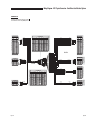
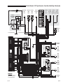
Electrical Schematic - 2011 Toyota Conversion - Power Door, Foldout Ramp & Kneel System
Kneel On/Off
Switch
31022
RD 8G
50 AMP
NO SWITCH
COM
MOMENTARY SWITCH
MOMENTARY SWITCH
85
RELAY
30
1 2 3
87
1 2 3 4 5 6 7 8 9 10 11 12
DRAWING NOTES
Junctions only occur at intersections with
junctions symbol. All other intersections
are wire crossings with out junctions!
VT 20G
VT 20G
OR 20G
WH/BK 20G
VT 20G
VT 20G
OR 20G
WH/BK 20G
WH/OR 20G
WH/VT 20G
OR/BK 14G
WH/RD/OR 14G
PK 20G
PK 20G
BK 20G
WH/BK 20G
WH 20G
BL/BK 14G
WH 14G
DK BL 20G
WH 20G
DK BL 20G
TN/WH 20G
WH/BK 20G
BN/WH 20G
VT/YL 20G
VT 20G
OR 20G
WH/BK 20G
WH 14G
WH 14G
OR/RD 14G
BL/BK 14G
BL/BK 14G
BK 14G
DK BL 20G
DK BL 20G
1 2
1 2
1 2 3 4 5 6
BK (Motor)
RD (Motor)
WH/BK 20G
WH 20G
TN/WH 20G
WH/BK 20G
BN/WH 20G
WH 14G
BL/BK 14G
Ramp Motor
36087A
M
COM
NO
NO 1
1 2 3 4 5 6 7 8
1 2 3 4 5 6 7 8
NC 3
Ramp
Stow
Switch
33421A
NC 6
5 COM
NO 4
WH/BK 20G
BK 20G
COM
NO
NC 3
2 COM
WH/BK 20G
TN/WH 20G
COM
NO
NO 1
1 2 3 4 5 6 7 8
WH/OR 20G
WH/VT 20G
OR/BK 14G
WH/RD/OR 14G
PK 20G
PK 20G
BK 20G
WH/BK 20G
WH 20G
BL/BK 14G
WH 14G
DK BL 20G
WH 20G
DK BL 20G
TN/WH 20G
WH/BK 20G
BN/WH 20G
WH/BK 20G
WH 20G
BK 20G
OR/BK 14G
WH/RD/OR 14G
2 COM
Kneel
Override
Switch
33469
1 2 3 4 5 6 7 8
RD 12G
BK 12G
RD/WH 14G
OR/RD 14G
BK 14G
OR/RD 14G
1 2 3 4
1 2 3 4
Gateway
Module
1 2 3 4 5 6 7 8 9 10 11 12
1 2 3 4 5 6 7 8 9 10 11 12
RD 12G
BK 12G
RD/WH 14G
OR/RD 14G
1 2 3 4 5 6 7 8 9 10 11 12 13 14 15 16 17 18 19 20 21 22 23 24
RD/WH 14G
Ramp
Override
Switch
33469
OR/BK 14G
OR/BK 14G
RD/WH 14G
WH/RD/OR 14G
WH/RD/OR 14G
BK 14G
1 2 3 4 5 6 7 8 9 10 11 12 13 14 15 16 17 18 19 20 21 22 23 24
WH/BK 20G
WH/OR 20G
WH/VT 20G
OR/BK 14G
WH/RD/OR 14G
PK 20G
PK 20G
BK 20G
WH/BK 20G
WH 20G
BL/BK 14G
WH 14G
DK BL 20G
WH 20G
DK BL 20G
TN/WH 20G
WH/BK 20G
BN/WH 20G
BK 14G
OR/BK 14G
WH/RD/OR 14G
RD 12G
WH/OR 20G
WH/VT 20G
PK 20G
PK 20G
DK BL 20G
WH 20G
DK BL 20G
VT/YL 20G
VT 20G
OR 20G
WH/BK 20G
WH/BK 20G
WH 20G
BK 20G
GRN
WH 14G
OR 20G
BN/WH 20G
TN/WH 20G
BK 14G
BL/BK 14G
DK BL 20G
DK BL 20G
WH 20G
WH 20G
PK 20G
PK 20G
WH/OR 20G
WH/BK 20G
WH/VT 20G
1
GRN
Rear Fuse Block
DK BL 20G
WH 20G
LT GN 20G
DK BL 20G
LT BL 20G
GY/RD 20G
PK 20G
PK 20G
VT 20G
VT 20G
WH/BK 20G
WH 20G
1 2
BK 22G
RD 22G
WH/BK 20G
WH 20G
BK 20G
OR/BK 14G
WH/RD/OR 14G
RD/WH 14G
OR/RD 14G
RD 12G
4.7 K
Ramp
Deploy
Switch
34806
Kneel
Lowered
Switch
31784WP
NC 6
5 COM
NO 4
WH/BK 20G
BN/WH 20G
COM
NO
BL/BK 14G
WH 14G
20 AMP
25 AMP
25 AMP
GY/RD 20G
OR/BK 14G
WH/BK 20G
WH/VT 20G
WH/OR 20G
WH/RD/OR 14G
BK 20G
WH 20G
RD/WH 14G
B-Pillar Door
Switch
34454
1 2
DK BL 20G
BK 22G
RD 22G
DK BL 20G
WH 20G
PK 20G
PK 20G
VT 20G
VT/YL 20 G
Bat.
WH/OR 20G
WH/VT 20G
WH/BK 20G
OR/BK 14G
LT BL 20G
WH/BK 20G
WH/BK 20G
RD 20G
1 2 3 4 5 6 7 8 9 10 11 12
3 AMP
20 AMP
3 AMP
WH 20G
BK 20G
WH/RD/OR 14G
RD/WH 14G
DK BL 20G
86
87A
BK 14G
RD 20G
RD/WH 14G
GY/RD 20G
RD 20G
1 2 3 4 5 6 7 8 9 10 11 12 13 14
BK 14G
RD/WH 14G
BK 14G
1 2 3 4 5 6 7 8 9 10 11 12 13 14
1 2 3 4 5 6 7 8 9 10 11 12 13 14 15 16 17 18 19 20 21 22 23 24
1 2 3 4 5 6 7 8 9 10 11 12 13 14
1 2 3 4 5 6 7 8 9 10 11 12 13 14
1 2 3 4 5 6 7 8 9 10 11 12 13 14 15 16 17 18 19 20 21 22 23 24
BK 22G
RD 22G
1
OR 20G
1 2 3 4
RD 22G
BK 22G
RD 22G
BK 22G
OR 20G
RD 12G
TO: Console Power Outlet
1 2 3 4
DK BL 14G
DK BL 20G
WH 20G
PK 20G
VT 20G
DIODE
RD 12G
WH/BK 20G
DK BL 20G
NC
NO
TN/WH 20G
WH/BK 20G
BN/WH 20G
WH 14G
BL/BK 14G
1 2
OR 14G
NO
COM
1 2
1 2
1
VT 20G
VT 20G
1 2
M
NC SWITCH
DK BL 20G
DK BL 20G
WH 20G
WH 20G
PK 20G
PK 20G
1 2
WH/BK 20G
WH/VT 20G
GRN
1 2
1
DK BL 20G
WH 20G
PK 20G
VT 20G
FUSE
COM
RD 22G
BK 22G
87A
YL 20G
DK BL 14G
DK BL 20G
TO OEM
TO OEM
Pass Door
Pass Door
Ajar (Switch) Ajar (Body)
VT 20G
VT/YL 20G
NO
4.7 K
1 2 3
DK BL 20G
LT GN 20G
TO OEM
Door Body
Harness
DK BL 20G
WH 20G
PK 20G
VT 20G
4.7 K
RD 22G
BK 22G
OR 14G
WH/BK 20G
RD 12G
DK BL 20G
87
30
WH/BK 20G
TO: Console Power Outlet
8
BATTERY
1 2 3 4 5 6
COM
RD 12G
Page 19A
TO OEM
Door
Harness
1 2 3 4 5
NO
86
GRN
Braun
Kneel
Module
P??
CHASSIS GROUND
YL 14G
Braun
SmartBox
Controller
Assembly
SYMBOL
CONNECTORS
(P-Plug & J-Jack)
MOTOR
IGN
Braun
Ramp
Module
DESCRIPTION
1 2 3 4 5
85
30 AMP
3 AMP
BAT
Door Full
Open Switch
36113
RD 12G
RD 12G
RD 8G
Dash Door
Switch
34454
JUNCTION
Front Fuse
Block Assembly
E90375A
30 AMP
RD 8G
E91086A
Battery
Dash Door
Switch
34454
WH/BK 20G
OR 20G
RD 8G
BK (Motor)
RD (Motor)
M
Kneel
Raised
Switch
31784WP
Kneel Motor
33440
Page 20A
E
Po l e c U
Ra w tr nf
m er ica ol
p
l d
& Do Sc fo
K or he r:
ne , F m
el ol at
Sy do ic
st ut
em
Exploded View - 2011 Toyota Conversion - Foldout Ramp Platform Assembly
5
10
2
3
16
9
14
7
13
12
13
6
16
4
8
15
1
11
Page 19B
Page 20B
REPLACEMENT PARTS
2011 Toyota Conversion - Foldout Ramp Platform Assembly
Item
Qty.
1
1
Description
Part Number
RAMP-EXTENSION/29.25" AUTO/2008 CHRYSLER
E50262??-08
2
1
RAMP-BASE/29.25" AUTO/TOYOTA
3
2
SCREW-#10-32X1/2 FHDHXS-AUTO BLK-W/PATCH
4
2
NUT-#10-32 W/LOCKWASHER/AUTO-BK
E90334??
17192P
18349
5
1
HINGE WMT.-S.S. 2" X 1/4" X 29"
6
2
WASHER-1/4" FLAT/AUTO-BK
18619W029
10062
7
2
BOLT-1/4-20X3/4"BHCS NYLK/BKZN
25371
8
1
CAM-CAST RAMP
34317
9
20
SCREW-#10-32X5/8 FHSC-AUTO BLK/PATCHED
10
20
NUT-10-32 HEX CENTER LOCK/AUTO-BK
11
2
BUMPER-RUBBER RECES.31/32 OD
12
1
CHAIN-NICKEL PLATED #35 ROLLER X 9.38"
13
2
LINK-CHAIN #35
14
1
BRACKET-CABLE TENSIONER/OUTER/BLACK
32954P
34290BK
10950
84314R009.38
12454
52568-2908BK
15
1
DECAL-WARN CHAIN HAZ RAMP EVII
16
3
#6 NYLON WASHER
82070-000
26134
17 *
1
SHRINK TUBING-1/2" X 7"
14374R007
* Item not shown
Page 21
REPLACEMENT PARTS
2011 Toyota Conversion - Foldout Ramp Gear, Motor and Base Assembly
Item
Item
Qty.
Qty.
1
1
Description
Description
GEARMOTOR ASSY-KLAUBER/RIGHT ANGLE
2
4
NUT-SHOULDER 3/4" HEX/0.27 H
3
1
STOW SWITCH SLIDER
4
1
SUPPORT-GEAR MOTOR/FOLDING RAMP/08RT
5
1
ASSEMBLY-FOLDING RAMP STOW SWITCH
6
2
WASHER-1/4" FLAT/AUTO-BK
Part Number
Number
Part
36087A
32385
E40481
E51179BK
33421A
10062
7
1
BOLT-1/4-20 X 3" TAP / ZINC PLATED
23976ZP
8
1
NUT-#4-40 w/LOCKWASHER/AUTO-BK
19537
9
4
BOLT-1/4-20 X 1/2 BUT HD SOC/AUTO-BK
10
1
CAM-MICRO-SWITCH ADJUST-EV
11
1
COLLAR-SPLIT-3/4" SHAFT/RMP MTR/INNER/BK
15733
52573-2905
52565-2905BK
12
4
SCREW-1/4-20 X 1" SOC HD CAP
24221
13
1
BOLT-1/4-20X3/4"BHCS NYLK/BKZN
25371
14
1
PIN-RAMP SUPPORT-96SC 29" RAMP
51815-2905
15
1
LATCH BOLT-SUPPORT-29" RAMP
51541-2905
16
2
WASHER-NYLON 1/4IDX11/16X.030
12690
17
1
NUT-1/4-20 HEX LOCK/AUTO-BK
10775
18
1
SCREW-#10-32 X 5/16" SET/AUTO-BK
11562
19
1
MICRO SWITCH-EATON-FLR LVL/CUPPED
34806
20
2
SCREW-#4-40 X 3/4" RD. HD./AUTO-BK
11483
21
1
PLATE-TAPPED #4-40 MICRO SWITCH
24998
E40268W-07BK
22
1
WMT-ARM-DRIVES RAMP-GEAR MTR
23
1
THRESHOLD-RAMP/PASS
24
4
SPACER-.500" O.D. X.266 I.D. X .655 LONG
25
4
SCREW-1/4-20 X 1-1/4 FHSC
26
4
SCREW-5/16 X 3/8 SHLD SKT HD/SS
Page 22
E90306W??
E90321
81027-000
82882
Exploded View - 2011 Toyota Conversion - Foldout Ramp Gear, Motor and Base Assembly
12
11
13
10
14
9
1
15
“A”
18
22
3
24
16
7
6
17
6
16
23
2
4
20
19
25
26
5
21
8
Detail “A”
Page 23A
Page 24A
ot Fo Ex Un
or ldo plo fo
an ut de ld f
d Ra d or
B m Vi :
as p e
w
e
A Ge
ss ar
em ,
bl
y
M
Exploded View - 2011 Toyota Conversion - Foldout Ramp Assembly
6
11
3
5
2
1
3
5
11
6
5
9
12
10
13
8
4
Page 23B
Page 24B
REPLACEMENT PARTS
2011 Toyota Conversion - Foldout Ramp Assembly
Item
Qty.
1
1
Description
RAMP ASSY/2011
Part Number
E90334??A2911
2
1
ASSY-GEARMOTOR/ARM/BKT/2011
3
2
BEARING-FLANGE-5/8" X 1/4"-10FDU04
E90306A??
28435
4
2
SCREW-1/4-20 X 3/8" FLBHSCS-
28252
5
3
BOLT-3/8-16 X 3/4" FLBHSCS-GD8
6
2
PIVOT PIN/BUSHING/EV RAMP/2905
25171
7*
1
HARN - RIGHT ANGLE RAMP MOTOR
E60208A
8
1
RETAINER-BEARING
21451-03
9
1
BEARING-1/2ID X 1 1/8 OD-BALL
52571-2905
21371
10
1
WASHER-.519ID X .876OD X .074
12621
11
2
WASHER-.63 X .8 X .06 NYLON{10
83584
12
1
WASHER-UHMW 1.500 OD X .76 ID X 0.062
29680
13
2
WASHER-1/4 EXT STAR TOOTH LOCK ZP
83588
* Item not shown
Page 25
REPLACEMENT PARTS
2011 Toyota Conversion - Kneel Assembly
Item
Item
Qty.
Qty.
Description
Description
1
1
2*
1
KNEEL SWITCH BRACKET
E50859BK
3*
1
HARN-KNEEL SWITCHES
E50880BK
ASSY-KNEEL BOX-TY
4*
1
SWITCH-ON/OFF ROCKER-KNEEL
5
1
ASSY-KNEEL ACTUATOR/2011
6
1
KNEEL LIMIT SWITCH MOUNT/2011
Part Number
Number
Part
E90277A
31022
E90162A-11
E90454D
7
1
KNEEL LIMIT SWITCH MOUNT/2011
E90454P
8
2
SWITCH-LIMIT/PLUNGER STYLE/WEATHER-PROOF
31784WP
9
4
SCREW-#8-32 X 1"-MCH TRUSS HD/AUTO-BK
19912BK
* Item not shown
Page 26
REPLACEMENT PARTS
Exploded View - 2011 Toyota Conversion - Kneel Assembly
6
8
9
7
8
9
5
1
Page 27
DIMENSIONS
Dimensions - 2011 Toyota Conversion - Foldout Ramp
D
B C
A
J
H
I
F
G
E
All dimensions are for reference only.
Foldout Ramp
Door Opening Usable Width (Slide Door)
A
33”
Door Opening Usable Height (Slide Door)
B
56”
Interior Height at Center of Van*
C
60”
Interior Height at Driver and Passenger Position**
D
59”
Ramp Length
E
52”
Ramp Width (Usable Clear Opening)
F
29-1/4”
Ramp Angle (with Vehicle Kneeled on Power Conversion)
G
7.3°
Interior Floor Length (Behind Front Seats)
H
51”
Overall Interior Floor Length (Flat Area)
I
82-1/2”
Interior Width at B Pillars
J
61-1/2”
Due to manufacturing tolerances both with the OEM vehicle and the conversion components, all dimensions may vary slightly from those shown.
Page 28
"Providing Access to the World"
®
Over 300 Braun
Dealers Worldwide
®
"Providing Access to the World"
International Corporate Hdqrs: P.O. Box 310 Winamac, IN 46996 USA
(574) 946-6153
FAX: (574) 946-4670
1-800-THE LIFT ®
®
Braun Lowered Floor Conversions
featuring 2011 Toyota Minivans
36146
September 2010
International Corporate Hdqrs: P.O. Box 310 Winamac, IN 46996 USA
1-800-THE LIFT ®
(574) 946-6153
FAX: (574) 946-4670
braunmobility.com™
Patent #6,825,628 B2
entervan.com™
All illustrations, descriptions and specifications in this manual are based on the latest product information available at the
time of publication. The Braun Corporation reserves the right to make changes at any time without notice.