1
AMTRAK
MAINTENANCE
MANUAL
SUPPLEMENT
Section
Section
Section
Section
A
B
C
D
G-79-6
1203-72
1350-79
2900-97
10400-10403
February
Baggage
Car
Baggage
Car
Sleeper
Car
Wheel
Car
15,
1982
A-O-1
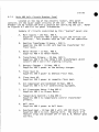
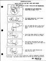
DRAWING
HEP
Conversion
by
RSI:
Circuits
Single
Line
and
Heat
64 Volt
Power
System
Trainline
Circuits
KC -312
KC-108
KC-122
Kc-g28
KC-956
KC-lO3
KC -305
KC-304
KC-318
KC-123
Selector
Switch
Wiring
Nelco
Heater
Wiring
AC Wiring
64V
DC Single
Line
Schematic
_7
Point
Trainline
Schematic
Electric
Locker
Ceiling
Lighting
Wiring
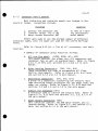
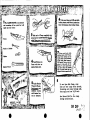
Reconversion
By
Beech
Grove:
Temperature
Control
Schematic
Single-line
Schematic
480V
Junction
Box
480V
Trainline
Schematic
27 Point
Trainline
Schematic
Electric
480
Volt
Locker
Wiring
Switchboard
Lighting
Switchboard
Loop
Relay
Panel
Marker
Light
Resistor
Heat
Contactor
Panel
Panel
C-04-456
C-04-457
D-04-458
KC-301
KC-313
Baggage
Car
Arrangement
Undercar
Arrangement
Receptacle
Arrangement
and
27 Point
Cable
Routing
480V
Trainline
Arrangement
Heat
Controls
HEP
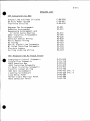
LIST
D-01-565
D-01-716
R-00-519
D-01-910
E-01-911
R-01-722
D-00-431
D-00-536
D-00-684
D-00-686
D-OO-7O4
sht.
-I
sht. -I
B-O-I
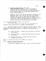
DRAWING
Beech
Grove
Converted:
Temperature
Control
Schematic
Single-Line
Schematic
480V
Junction
Box
480V
Trainline
Schematic
27 Point
Trainline
Schematic
Electric
Locker
480V
Switchboard
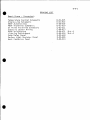
LIST
Wiring
Lighting
Switchboard
Loop
Relay
Panel
_larker
Light
Resistor
Heat
Contactor
Panel
Panel
D-01-915
D-o1-g12
R-00-519
D-01-910
E-Ol-911
E-04-913
D-00-431
D-00-536
D-00-684
D-00-686
D-00-914
Sht.-I
Sht.-I
C-0-1
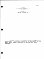
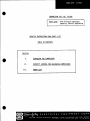
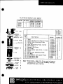
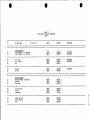
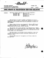
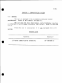
AMTRAK
MAINTENANCE
MANUAL
SUPPLEMENT
2900-97
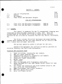
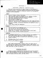
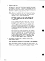
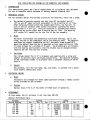
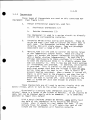
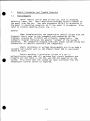
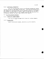
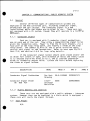
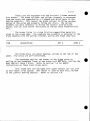
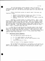
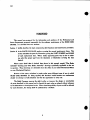
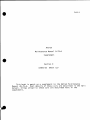
This
book
is
Manual
#G-79-6.
Most
manual;
things
unique
supplement.
SECTION
C
SLEEPING
G-79-6
CAR
meant
as a supplement
to the Amtrak
details
of these
cars are described
to these
cars
are described
here
in
Maintenance
in the main
the
x_
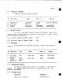
C-0-3
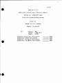
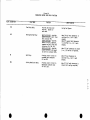
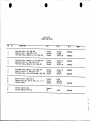
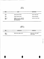
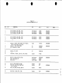
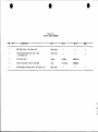
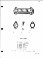
Figure
0.1
Maintenance
Manual
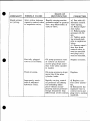
Revisions
DATE
CHAPTER
PAGES
CHANGES
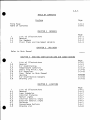
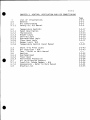
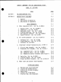
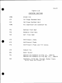
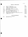
C-0-5
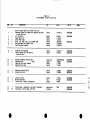
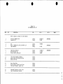
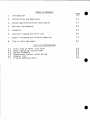
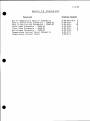
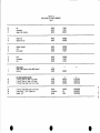
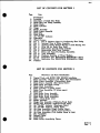
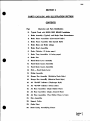
TABLE
OF
CONTENTS
Preface
Title
Table
Page
C-O-I
C-O-5
Page
of Contents
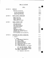
CHAPTER
i
1.0
1.1
List
of Illustrations
General
Car Numbers
1.2
Floor
Plans
and
Equipment
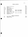
CHAPTER
Refer
to
Main
3
HEATING
Page
C-1-1
C-1-1
C-1-2
C-1-3
Weights
2
CAR
VENTILATION
BODY
AND
-
List
of
General
Illustrations
Lamp
Schedules
Interior
Fixtures
Marker
Lights
Interior
Consist
Signs
Exterior
Consist
Signs
Switches
Convenience
Outlets
Drawing
List
AIR
CONDITIONING
Page
C-3-2
C-3-3
C-3-7
C-3-17
C-3-43
C-3-43
List
of Illustrations
General
Air
Conditioning
Temperature
Controls
Shunt
Trip
Pilot
Light
Air
Vaporizer
Fans
Refer
to Main
Manual
Heating
Air
Distribution
Dampers
Drawing
List
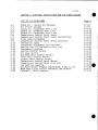
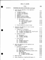
CHAPTER
i
4.1
4.2
4.3
4.4
4.5
4.6
4.7
4.8
4.9
GENERAL
Manual
CHAPTER
i
3.0
3.1
3.2
3.3
3.4
3.5
3.6
3.7
3.8
I
C-3-54
C-3-55
4
LIGHTING
Page
C-4-1
C-4-3
C-4-7
C-4-7
C-4-7
C-4-7
C-4-7
C-4-7
C-4-7
C-4-8
C-0-6
CHAPTER
5
COMMUNICATIONS
AND
PUBLIC
ADDRESS
Page
C-5-3
General
Tape
Player
Public
Telephone
Operating
Instructions
Audio
Instruction
Manual,
Safetran
Annunciator
Drawing
List
CHAPTER
i
6.1
6.2
6.3
6.4
6.5
6.6
6.7
6.8
6.9
6.10
6
7
7
7
7
7
7
7
7
7
System
System
ELECTRICAL
List
of
General
7
AIR
BRAKE
Page
C-6-2
C-6-3
C-6-3
C-6-3
C-6-3
C-6-4
C-6-8
C-6-15
C-6-28
C-6-28
C-6-29
SYSTEM
Page
C-7-1
Illustrations
Brake
System
Operation
- Refer
to Main
Manual
Carbody
Components
- Refer
to Main
Manual
Truck
Mounted
Components
Decelostat
Wheel
Slide
Protection
System
Brake
Condition
Indication
System
Maintenance
and Overhaul
Procedures
Brazing
Pipe
Procedures
Refer
to Main
Manual
Drawing
List
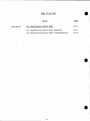
CHAPTER
Refer
CHAPTER
C-5-3
C-5-4
C-5-4
C-5-4
C-5-4
C-5-4
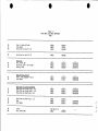
SYSTEM
List
of Illustrations
General
480 Volt Main
Power
Distribution
and
Cable
System
- Refer
to Main
Manual
27 Point
Trainline
Circuits
Battery
and Battery
Charging
System
Transformers
Switch
Locker
Electric
Locker
Food
Service
Electric
Locker
Panels
N/A
Service
Procedures
- Refer
to Main
Manual
Drawing
List
CHAPTER
i
N/A
N/A
N/A
N/A
9
8
to
FOOD
HANDBRAKE
Main
Manual
SERVICE
N/A
EQUIPMENT
C-7-3
C-7-3
C-7-3
C-7-3
C-7-13
C-7-23
C-7-23
C-7-23
C-7-23
C-0-7
CHAPTER
Refer
CHAPTER
11
10
to
Main
COUPLER
Refer
to
CHAPTER
Manual
AND
Main
12
List
of Illustrations
General
Undercar
and
Interior
Water
Cooler
Water
Heater
Insulation
Water
System
- Food Service
Water
Draining,
Filling
and
Refer
to Main
Manual
12.7
Drawing
DRAFT
GEAR
Manual
WATER
i
12.0
12.1
12.2
12.3
12.4
12.5
12.6
SYSTEM
Refer
Refer
Refer
to
to
to
Main
Main
Main
Manual
Manual
Manual
Refer
to Main Manual
Area
N/A
Flushing
Instructions
13
TOILET
Refer
CHAPTER
14
to
PERIODIC
Main
APPOINTMENTS
Manual
MISCELLANEOUS
Refer
15
Page
C-12-1
C-12-3
C-12-3
C-12-3
C-12-3
C-12-8
C-12-8
C-12-8
C-12-8
List
CHAPTER
CHAPTER
TRUCKS
to
Main
INSPECTION
Refer
to
CHAPTER
Refer
Main
16
to
Main
EQUIPMENT
Manual
AND
MAINTENANCE
Manual
RETROFITS
Manual
SCHEDULES
C-I-1
CHAPTER
i
1.0
1.1
1.2
1
List
of Illustrations
General
Car Numbers
Floor
Plans
and Equipment
List
1.1
1.2
Floor
Floor
1.0
Plan
Plan
and
and
of
Equipment
Equipment
GENERAL
Page
C-1-1
C-I-1
C-I-2
C-1-3
Weights
Illustrations
Arrangement
Arrangement
Page
C-1-I
C-1-2
2900-41
2980-97
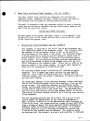
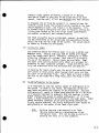
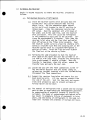
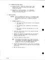
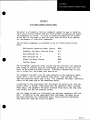
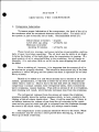
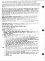
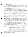
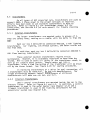
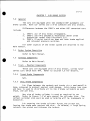
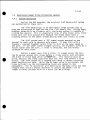
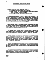
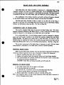
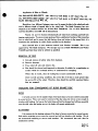
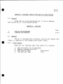
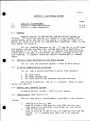
GENERAL
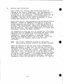
This
manual
is prepared
for
converted
to head
end power
beginning
accomplished
by the Amtrak
facilities
engineering
was provided
by Equipment
DC.
The
systems
were
volt
3 phase
The
direct
current
electrical
removed
and the cars were
head end power
operation.
maximum
minimize
Standard
inventory
Standard
HEP
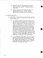
I.
2.
3.
4.
5.
6.
7.
8.
9.
I0.
11.
12.
13.
the 31 conventional
sleeping
cars
in June,
1977.
Work
was
at Beech
Grove,
Indiana;
Engineering,
Amtrak,
Washington,
operating
HEP equipment
and
facilitate
Equipment
speed
equipment
rewired
is
105
was utilized
maintenance.
mph
as
and steam
heating
for all electric
480
for
much
the
as
cars.
possible
to
Used:
Power
trainlines,
receptacles
and jumpers.
480 volt
power
junction
box.
Communication
trainline
receptacles
and jumpers.
Batteries
and battery
charger.
Conductors
signal
pushbuttons.
Marker
lamps.
Loop
relays.
Cars
are equipped
with
4 emergency
sash
units.
Rooms
equipped
with
new type
rugged
design
industrial
thermostat.
All
relays
and
contactors
are
stock
General
Electric
most
parts
are
interchangeable.
Some transformers
and
circuit
breakers.
Air
vane
switch
and
klixon.
Water
antifreeze
system.
type
and
C-1-2
Features
Floor
ii
To
These
Cars
heaters.
2.
Overhead
3.
A/C
heater
_Do
not
interchange
with
Std.
a.
Freon
b.
c.
d.
A/C starter
Compressor
Condenser
e.
f.
Evaporator
No reheat
out
together,
panel
and
blower
Controls
Switchboards
6.
CF
7.
P-3
8.
No
Fresh
9.
No
PA
10.
Floor
Heat
Transformers
HEP parts
can be used).
II.
No
12.
Water
i.I
Car
-
Lighting
and
480
V
(If
all
3 are
brakes
Pneumatic
Air
Decelostat
Damper
Unit
Brake
Applied
Heater
(Some
and
Released
parts
Pressure
common
to
changed
Switches
standard
HEP
cars).
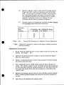
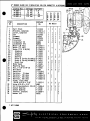
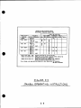
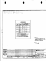
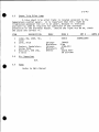
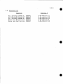
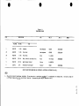
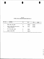
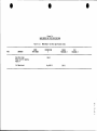
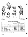
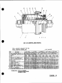
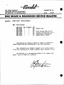
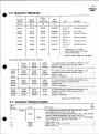
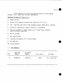
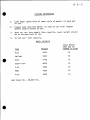
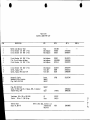
Numbers
QTY
New HEP
Number
Original
Number
Year
Built
13
18
2900-41
2980-97
2600-41
2710-33
1949
1949
cars
unit).
12
5.
All
HEP
System:
Temperature
.
Unique
are
10-6
sleepers
with
similar
appearance.
Builder
Budd
Budd
std.
C-1-3
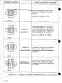
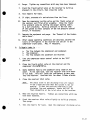
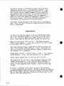
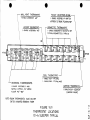
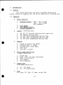
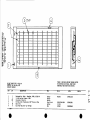
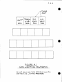
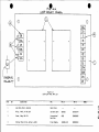
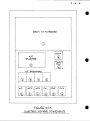
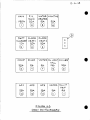
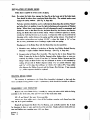
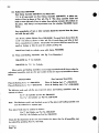
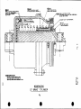
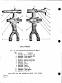
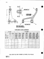
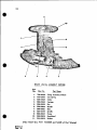
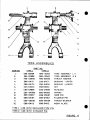
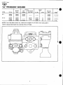
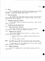
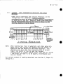
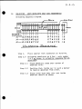
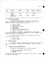
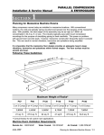
CHAPTER1.2
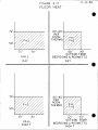
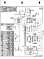
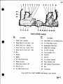
FLOOR PLANS, ARRANGEMENT
OF EQUIPMENT
AND CAR WEIGHTS
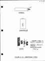
LEGEND
WC
LK
ELE
SWB
OHV
HB
WH
Water Cooler
Locker
Electric
Locker
Switch Locker
Overhead Unit (A/C)
Handbrake
Water Heater
THERMOSTATS:
RAT
FAT
FHT
Return
Fresh
Floor
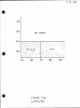
LHT
HHT
OHT
Layover
Heat
Thermostat
Hall
Heat
Thermostat
Overhead
Heat
Thermostat
Air
Thermostat
Air Thermostat
Heat
The_rmostat
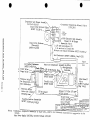
_1_,
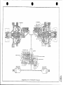
'A" END
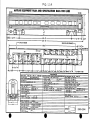
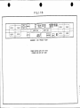
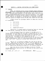
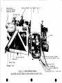
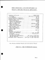
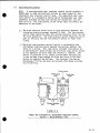
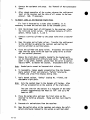
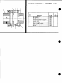
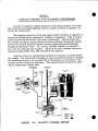
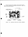
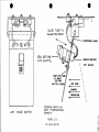
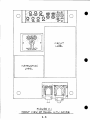
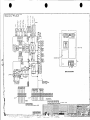
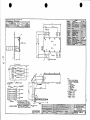
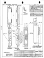
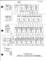
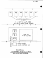
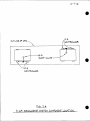
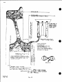
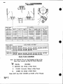
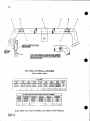
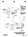
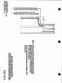
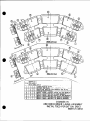
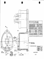
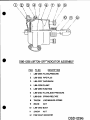
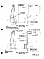
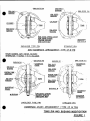
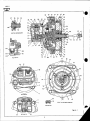
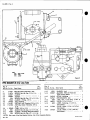
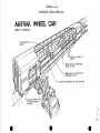
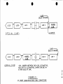
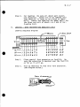
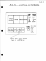
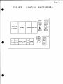
AMTRAK EQUIPMENT
PLAN AND
_.1_
SPECIFICATION
DATA FOR CARS
"B' END
[LECTR!CAL
SYSTEN
BATTERY
MODEL
SYANDB¥
RCPT._
COMM
EOUI_
. HEJ.D END POWER
_l, NO
TYPE"
N/A
ED/$ON
ED-O0
4
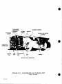
r'-(G. i.t
..... ___, ......
I
,
I
I
14.ovl [_
i
,(_
I_.ovl _._.o_._,
___.... r._ _.o_
T
.....
a .....
(
"---_
'_-.'
.....
7 T
......
, ........
-I L- ........
j_f-gA-;1
_
_
_
UNDERBODY
FORMER
L- .....
f_--ll_._6._l<i=_lll
12.1I'l
AMTRAK
CARS'
VIEW
2600,.
(FORMER
_--_J
I
i/ II-R
_.sLJ II _
THROUGH
-
,_.....
)
)
,
,,
"-.....
_-_--i .......
l_-'r
.....
_ .....
;
FLOOR
41
CARS_
UP
1401-
1449)
EQUIPMENT
ENGINEERING
-
FEBRUARY,1978
r.- I
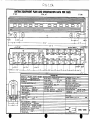
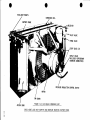
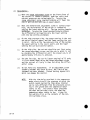
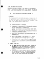
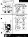
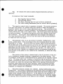
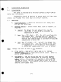
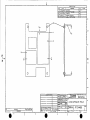
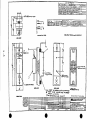
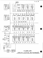
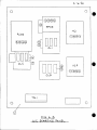
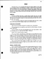
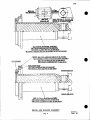
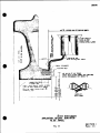
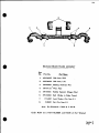
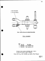
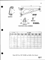
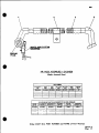
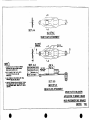
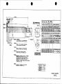
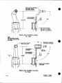
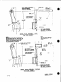
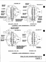
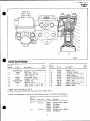
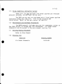
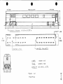
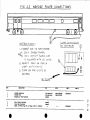
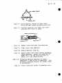
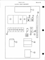
AMTRAK
EQUIPMENT
PLAN
AND
'A' END"
SPECIFICATION
TOTAL
DATA
FOR
WT."
'B'
17"
BATTERY
MOOEL
VOLTAGE
64
LIGHT_NG
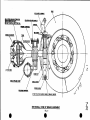
WHEEL
OiA.:
36"
CLASS:
JOURNAL
_
BrU_RING
TYPE:
BOtSTER
EPRn_GS,
RE
P{0ESTAL
EOUALIZER
ROLLER
ADAPTER
COMM
SPRING
SHOCKS"
VERT,
WEtG:_T
FREEZE
TYRE:
_NTI
FREEZE
NO.:
BRAKES
TYPE:D8
CONTROL
RELAY
NO
LAT.
¸ 'A" END,
(CFM!
VALVE
_¢4_VE
ANTt-SLIDE
'B'
TYPE
TYPE
TrPE"
F-6
AP-Jr
OU_CK
H_O
NO'
ENO_
-SGHEOULE
O22
BRAKE
C_I_INOER
EOUIP
ANTI
TYPE:
¸
SERVM3E
TyPE:PK
SJZE ¸ •
RO0
L
B
NO
EDISON
EO-80
NOM
CAPY
AC:F'LUOR
SJZE:
No:
CARS
TYPE"
OE
80_4H
/NC
N/.4
('_AFING
[ I._E,41"//v_
TAPE
T,4PE
_4TER
°
UNDER
C.4R
TANKS
,o/pING
{2]
END:
_I c), I ,"L_
I
I
J---I.
¢_
I
r
:_'_
I
I
I_.t
I
(
j_
'
t
I
%w _l_
.( A,,,}r--3
BATTERY
._--:" !( A,R )I
I
.J_
' ....
b
i
I
I
I
I
.ATERTANK
'
I
.
WATER
_'_'
TANK
t_........
j'
I
r
......_-_ "
I
"F
_-
(
I
"_'P--_" ....
__ ....
l
J ........
_
I
I--
BATTERY
UNDERBODY
FORMER
(FORMER
VIEW
AMTRAK
THROUGH
CARS"
CARS:SFE
FLOOR
;>710-2753
1617-1632)
!
I
C-2-I
CHAPTER
Refer
to
2
Main
CAR
BODY
Manual
C-3-I
i
3.0
3.1
3.1.1
CHAPTER
3
HEATING,
List
of
General
Illustrations
Air
Conditioning
Safety
Co. A/C
VENTILATION
AND
AIR
CONDITIONING
Page
C-3-2
C-3-3
C-3-7
C-3-9
Manual
3.2
3.2.1
3.2.2
3.2.3
3.2.4
3.2.5
3.2.6
3.2.7
3.2.8
Temperature
Controls
Panel
Description
Thermostats
3.3
3.4
3.5
3.6
3.6.1
3.6.2
3.6.3
3.7
3.7.1
3.7.2
3.8
Shunt
Trip
Pilot
Light
Air
Vaporizer
N/A
Fans
- Refer
to Main
Manual
C-3-43
C-3-43
Heating
Overhead
Heat
Floor
Heat
Antifreeze
Protection
C-3-44
C-3-45
C-3-49
C-3-54
C-3-54
C-3-54
C-3-54
C-3-55
Blower
Logic
Cooling
Logic
Overhead
Heat
Logic
Floor
Heat
Logic
Damper
Logic
N/A
Temperature
Control
C-3-17
C-3-17
C-3-23
C-3-30
C-3-30
C-3-33
C-3-37
wa_.
Panel
Manual
Air
Distribution
Dampers
Fresh
Air
Intake
Damper
N/A
Annemostats
Refer
to Main
Manual
Drawing
List
C-3-41
C-3-2
3.1
3.2
3.3
3.4
3.5
3.6
3.7
3.8
3.9
3.10
3.11
3.12
3.13
3.14
3.15
3.16
3.17
3.18
3.19
3.20
3.21
3.22
3.23
3.24
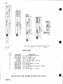
CHAPTER
3
LIST
ILLUSTRATIONS
OF
HEATING,
VENTILATION
AND
AIR
CONDITIONING
Page#
Fresh
Air - Return
Air
Balance
Air
Filter
Systems
Safety
Co. Evaporator
Part List
Safety
Co. Condenser
Part
List
Safety
Co. Compressor
Part List
Temperature
Control
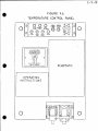
Panel
Cover
Temperature
Control
Panel
Cover
Instructions
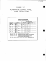
Pilot
Lamp
Assignment
Temperature
Control
Panel
Relay
Functions
Thermostat
Types
Thermostat
Assignment
and
Function
Heating
and A/C
Thermostat
Thermostat
Location
Part
List
Cooling
Control
Points
Air
Vane
Switch
Overhead
Heat
Control
Points
Floor
Heat
Control
Points
Layover
Heat
Control
Points
Temperature
Control
Panel
Manual
Temperature
Control
Panel
Part
List
Car Heating
Capacity
Overhead
Heater
Element
Replacement
& Part
List
Room
Heat
Local
Circuit
Breakers
and Control
Teleweld
- Built
Heaters
C-3-4
C-3-5
C-3-10
C-3-11
C-3-12
C-3-19
C-3-20
C-3-21
C-3-22
C-3-25
C-3-27
C-3-28
C-3-29
C-3-31
C-3-35
C-3-36
C-3-38
C-3-39
C-3-41
C-3-42
C-3-44
C-3-46
C-3-51
C-3-52
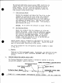
C-3-3
CHAPTER
3.0
3
HEATING,
VENTILATION
& AIR
CONDITIONING
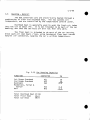
General
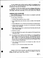
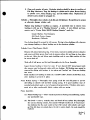
NOTE:
All
HeatinB
and
A/C
circuit
breakers
should
remain
on
_ear
round.
While
it may
seem a good
idea to turn off the A/C
breaker
in the winter
or heating
breakers
in the summer,
this
is not the
case.
The temperature
controls
will
turn on the heat or A/C as needed
and have logic
interlocks
to prevent
incorrect
operation.
Also,
while
it might
be cool
in one
part
of the country,
it may
be hot in another
region.
Many
of the heating
or cooling
failures
reported
on HEP cars
have
been caused
by breakers
being
off when
they
should
not have
been.
of
car
Climate
4 operations:
from
control
1.
Ventilation
2.
Circulation
3.
Filtration
4.
Temperature
for
passenger
comfort
on
these
cars
consists
Control
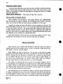
Ventilation
is accomplished
outside,
replacing
the stale
by introducing
fresh
air
being
exhausted.
air
into
the
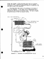
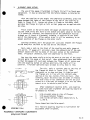
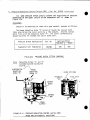
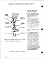
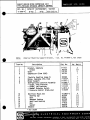
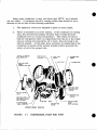
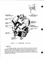
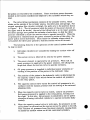
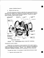
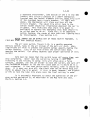
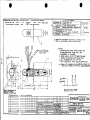
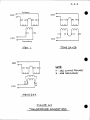
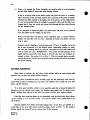
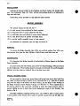
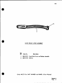
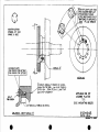
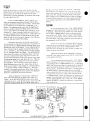
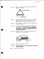
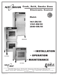
A one
horsepower
blower
fan (unique
to the 2900
cars)
is
located
above
the vestibule
ceiling,
and is responsible
for car air
circulation.
It takes
fresh
air,
normally
600 cfm,
and mixes
it with
recirculated
air,
delivering
2,400
cfm to the car's
main
air duct.
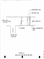
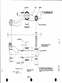
(See
Fig. 3-1)
The blower
is also
responsible
for car
pressurization.
To keep dust and
dirt
out of the car,
the car is kept
slightly
pressurlzed.
Thus,
all the tiny
openings
in the carbody
will
have a small
draft
flowing
out through
them,
keeping
dust
and
dirt
Out.
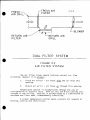
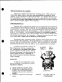
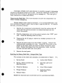
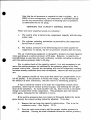
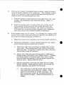
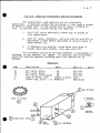
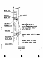
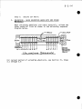
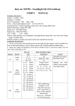
The car
air is filtered
to remove
dirt
and lint
by the air
filters.
These
cars
use two sets
of filters,
one
for fresh
air,
and
one
for recirculating
air (See
Fig.
3-2).
It is very
important
to
keep
these
filters
clean
(as well
as the thermostats).
Otherwise,
the
car air conditioning
and
heating
system
will
not function
properly.
through
side of
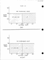
Air
Note
that
the air
filters
them
in only
one direction,
the frame.
Filter,
16"
x
20"
x 2"
are
as
AMT
meant
to
indicated
#24A9001385
have air
flowing
by the arrows
on
AMMS
#
the
EVAPORATOR
COIL
--
/
FRESH
AIR
600 CFM
/
--
HEATING
COIL
4
2400
Z
BLOWE
R
'#MAIN
CFM
'====¢>
DISTRIBUTION
DUCT
RETURN
AIR
1800 CFM
FIGURE
FRESH
5.1
AIR / RE TURN
AIR
BALANCE
('b
I
OJ
I
eu
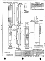
_- FRESH
AIR
c-3-5
i F,LT
fi _/_
/
L
,
FI LTER
BLOWER
GRILL
DUAL FILTER
AIR
The
direction,
car
filter
however
it
FIGURE
FILTER
frame
is
1.
Fresh
Air
opening.
2.
Return
air
should
SYSTEM
5.2
SYSTEM
indicate
correct
air
flow
always:
Filter
- air
flows
into
grill
air
flows
up
the
through
car
from
this
this
opening.
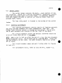
Temperature
control
is accomplished
through
the use of
refrigeration
or electric
heat.
Each car
has one 8-ton
cooling
located
in the ceiling.
Heating
is accomplished
by a combination
overhead
and floor
heat,
independently
controlled.
heating,
A single
cooling
temperature
control
and ventilation.
panel
controls
all
aspects
unit
of
of
C-3-7
3.1
Air
Conditionin
9
Each
car
is
conditioning
system.
interchangeable
with
equipped
with
a single
Safety
Co. 8-Ton
The
system
uses
R-12 and
parts
are not
the freon-22
system
of later
converteTHEP
air
cars.
Evaporator
The push-through
evaporator
is located
almost
above
the
vestibule
of the car,
along
with
the direct
drive
blower
fan.
The
evaporator
is split
into
two stages
for 1/2 and full cooling.
Included
with
the
overhead
assembly
are the modulation
valve,
a
moisture/flow
indicator
and
strainer.
The unit
is also
equipped
with
a two stage
overhead
heater.
Condenser
the
(on
The air
coil
itself,
the back).
cooled
condenser
is located
the fan and motor,
and the
undercar,
modulation
and consists
of
pressure
switch
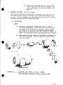
Compressor
The open-frame
compressor
and
near
the condenser.
Included
undercar,
controls.
Startin
9
drive
with
motor
it
are
are
located
the
pressure
Panel
The
includes
the
contactors.
The
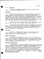
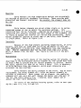
I.
.
A/C
starter
panel
is located
in the electric
locker
A/C
logic
relays,
blower
fan, compressor,
overhead
Refer
to Figure
6-14
for parts.
A/C
logic
Lockout
Overload
compressor
reset
is
includes
below
the
following
50 .° outside
air
safety
features:
temperature.
relays
for blower
fan, condenser
fan
motors
to protect
against
overload.
required
on each.
3.
Air
Vane
evaporator
Switch
& Blower
Fan
freeze-up,
should
4.
Low pressure
resetting.
5.
High
pressure
resetting.
shutdown
shutdown
(but
(but
interlock
the blower
not
not
and
lockout)
lockout)
and
Manual
to prevent
fail
to operate.
self
- self
C-3-8
Freon
Charge
The
weight
of
a
full
40
Compressor
both
charge
of
with
For a complete
description
list and maintenance
instructions,
Section
3.1.1.
For
3.6.
A/C
system
tests,
DESCRIPTION
Freon
Freon
11
Brazing
Alloy
Silicon
Compound
refer
to
be
Amtrak
utilized
#
test
MANU.
Terminal
oz
tube
Handy
Harmon
&
#
spec.
as well
as parts
Co. Manual,
P0-79-I
AMT
47L9001790
........
("Silver
Solder")
AMMS
in
can be safely
intermixed,
(except
WFI 32) oils
should
when
being
replaced
with
pumped)
CF
CL
Kit
2
may
- .......
(Water
220
Test
oils
of the A/C
system
refer
to the Safety
MANU.
12
Nitrogen
Acid
approximately:
Texaco
Although
Sunisco
3GS and Capella
B
other
grades
of Sunisco
and Texaco
not be mixed,
but should
be drained
the standard
oil.
and
is
Oil
Until
further
notice,
the following
Amtrak
air conditioning
systems:
Sunisco
3GS
Note:
12
pounds
Texaco,
Type
Capella
B*
* Capella
B may
be replaced
3.3
freon
47BgOO34gg
SILFOS
Safety
T15583
Dow-
#3
25A4000275
tests
#
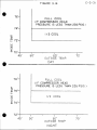
3.2,
AMMS#
C-3-g
Section
Operating
3.1.1
Instructions
Safety
8-Ton
Co.
Air
Conditioning
Weight
of
Compressor
Condenser
Evaporator
40
Sunlsic
Texaco
Texaco
Valve
Coil
Manual
Type
System
12
Full
Approx.
Solenoid
Service
Component
Freon
Oil:
&
Charge
pounds
3GS
Capella
WFI32
Resistance
Motor
Resistance
Fan Motor
Resistance
Fan Motor
Resistance
ohms
ohms
ohms
ohms
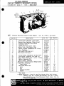
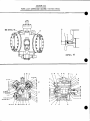
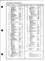
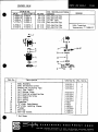
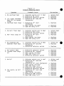
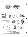
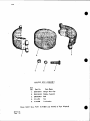
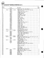
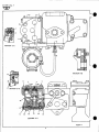
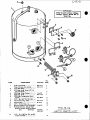
Figure 3.3
A/C EVAPORATO_
- SAFETY CO. PART LIST
ITEH
QTY
1
1
1
I
4
2
DESCRIPT[ON
Refer to Safety Nanual for Further Part Lists
Evaporator Blower Fan & Motor Unit Cemplete (Not same
as ether HEP cars)
Air Flow Switch
Blower Wheel Left
Blower Wheel Right
Hotor 1HP
480V 3_, 1.5A, 1725 RPH, 182T
Resilient le_untSat (Frame to Car)
Shaft Extension Assembly
HFG
HF6 #
M4T |
Safety
B-1434-15
23X9012879
09ontz
Safety
Safety
Baldor
Safety
Safety
8373-214
T-1793-4
T-1793-3
38N73-287
T-13706-5
T-14037-3
25H9012249
25H9011513
1
Evaporator Unit Complete
Electric
Heater Unit (Not same as
other BEP cars)
Safety
Safety
B-1444-17
8-4319-1
25T9011509
25P9011518
1
2
2
2
Overheat Thermostat "Kltxon" 200°
Expansion Valve
(ALCO)
Expansion Valve Power Element
Expansion Valve Cage
Texas Inst.
Safety
Safety
Safety
C439157442-0_
T-3695-1
T-7339-1
T-11S_
231)9006951
251.9011519
14
15
Modulation Solenoid Valve
Solenoid Valve Coll
Safety
Safety
T-3330-1
T-7820-4
25K9011514
25E9011515
16
17
18
Strainer,
Hotsture
Flexible
Safety
Alco
Safety
T-15531
MI-1SSS
B-4409
23A4000306
23A4000305
Reeves Bros.
Aerotube
2209
--
23X9007382
46N9001208
10
I1
12
13
"19
20
1
AR
..mmmk
Liquid
Indicator
Duct - Blower to Evaporator
Flexible
Duct - Evaporator to Car Duct,
Insulation,
2 1/8" ID Fom, l/Z ° Wall
"Flextduct _
AJeIS #
!
_o
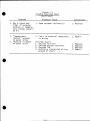
I
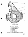
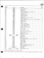
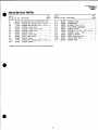
A/C
ITErl
QTY
DESCRIPTION
Refer
to Safety
Co. Manual
for further
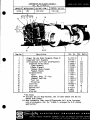
Figure 3.4
COI_DENSER PART LIST
MFG
MFG #
Safety
Safety
B-2442-14
B-1566
Safety
Baldor
Safety
M-1890-2
T-12967-2
T-13706
163748
8 Ton Dry Condenser
Condenser Coil
Unit
3
4
5
Fan
Motor - Condenser
Liquid Receiver
6
7
8
Sight Glass, Receiver
Resilient Mount Set
Pressure Switch, Modulation
Safety
Safety
Safety
9
10
11
Filter Drier Ass(_nbly, Complete
Gasket, Outlet Core Retaining Plate
Gasket, End Plate
Safety
Safety
Safety
12
13
14
Core, Filter Drier
Shut Off Valve, Liquid Line at Drier
Vibration Eliminator, Liquid Line
Safety
Safety
Safety
15
16
Vibration Eliminator, Hot Gas Line
Sight Glass/Moisture
Indicator
Safety
Safety
2HP,
1725 RPM
#
AMMS
#
Details
I
2
Fan,
AMT
3.1A
25K9010511
25T9011512
M-1782
25A9001569
I
{#
4
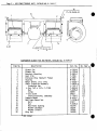
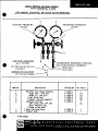
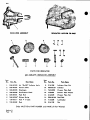
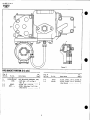
Figure3.5
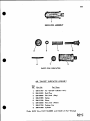
A/CCOMPRESSOR
AND
COMPRESSOR
UNITPART
LIST
ITEM QTY
DESCRIPTION
For Further
MFG
MFG
#
B-3988-4
161705
AMT
#
1
2
I
I
Details, Refer to Safety Manual
Direct Driven Compressor Unit, 8 Ton
Compressor (Form 5295) 5F40
............
Safety
Safety
3
4
5
I
I
I
Coupling, Thomas
Motor, 15 HP, 1760 RPM,
Resilient Mount Set
Safety
Baldor
Safety
161685
6
7
8
1
(I)
(1)
Refrigeration Controls
High Pressure Gauge
Low Pressure Gauge
Safety
Safety
Safety
B-289g-2
T-16284-I
T-16283
25A4000064
25A4000065
9
10
11
(I)
(I)
(I)
Manual Selector Switch
High Pressure Switch
30-270
PSI
Low Pressure Switch
20" Vacuum - 120 PSI
Safety
Allen Bradley
Alien Bradley
S-8816-2
836 HI1 XHCS
836 ALl1NKCS
25X9011517
25A8000451
25D9006178
12
13
14
(I)
(I)
(2)
Box Cover
Box Seal
Service Valve
Safety
Safety
Safety
T-2964
T-1816g
114
115
I
I
2
REF
Vibration
Vibration
Compressor,
Eliminator,
Eliminator,
19-7A, 480/3/60
Assembly,
Complete
Suction Line
Discharge Line
5F40
New Built
Rebuilt
15A
15B
16A
16B
I
I
4
4
Suction Shut Off Valve,
Suction Shut Off Valve,
Cap Screw for Item 15A,
Cap Screw for Item 15B,
1 5/8"
1 5/8"
20A
20B
17
18
19
1
2
2
Gasket, Cap Screw (Item 15)
Valve Cap (Item 15 and 20)
Valve Cap Gasket
(Mueller)
(Henry)
AMMS
#
25N9010510
25X9011511
T-13623-2
Safety
Safety
Safety
Safety
161705
T-11902-I
Safety
Safety
Safety
Safety
162481
T-4945
162482
54825
Safety
Safety
Safety
151303
T2467
T2466
C_
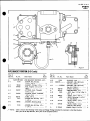
I
A/C
20A
20B
21
Shut Off Valve,
Shut Off Valve,
Gasket, Suction
COMPRESSOR
Figure 3.5
AND COMPRESSOR
Page 2
Discharge (Mueller)
Discharge (Henry)
or Discharge Valve to Crankcase
UNIT
PART LIST
Safety
Safety
Safety
162480
T4924
162497
Replacement Gasket Set
Main Bearing, Seal End
Dowel Pin, Valve Plate
Oil Return Check Valve Package
Safety
Safety
Safety
Safety
162510
161978
T-2464
162126
22
23
24
25
-(I)
(4)
2
26
27
28
2
1
1
Cylinder Head Gasket
Suction Strainer _ssembly
Oil Filter Screen Package
Safety
Safety
Safety
162487
162032
T2455
Z9
30
31
1
1
6
Manifold Cover Gasket
Oil Regulating Valve Package
Cap Screw 3/8 - 16 x i" (Manifold
Safety
Safety
Safety
162486
T2465
157557
32
33
34
28
34
I
Cap Screw 3/8 - 16 x 3" (Cylinder
Cap Screw Gasket (3/8)
Shaft Seal Package
Safety
Safety
Safety
162424
151286
T1401
35
36
37
38
8
I
(I)
(i)
Cap Screw 3/8 - 16 x I - I/4 (Shaft Seal Cover)
Bearing Head and Oil Pump Assembly Includes:
Bearing Head Gasket
Main Bearing, Pump End
Safety
Safety
Safety
Safety
151375
T2462
162493
162429
39
40
41
(3)
(12)
(6)
Cap Screw Gasket (518")
Cap Screw Gasket (3/8") (Bearing Head)
Hex Head Cap Screw I/4 - 28 x 3/4 (Oil Pump Cover)
Safety
Safety
Safety
T2466
151286
164363
42
43
44
45
46
(6)
(1)
(1)
(I)
(1)
Cap Screw Gasket (1/4")
Dowel Pin (Bearing Washer)
Oil Pump Package (Matched Parts)
Oil Pb_np Cover Gasket
Bearing Head Gasket
Safety
Safety
Safety
Safety
Safety
163534
T2463
T13006
T12652
162493
Cover)
Head
Suction
Manifold)
I
L_
A/C
47
48
49
5O
51
52
53
54
55
56
57
58
59
60
61
62
12
I
I
Hex Head Cap Screw (318 - 16 x 1-314")
Cover)
Woodruff Key #21
Retaining Washer (3/8")
COMPRESSOR
(Bearing
Head
Figure 3.5
AND COMPRESSOR
Page 3
UNIT
PART LIST
Safety
T245g
Safety
Safety
162505
162450
1
1
4
Lockwasher (318")
Cap Screw (3/8 - 24 x 7/8")
Connecting Rod and Bearing Package
Safety
Safety
Safety
4411
162502
T2451
1
1
1
Bearing Washer, Pump end
Seal End Thrust Washer (steel)
Seal End Bearing Washer (bronze)
Safety
Safety
Safety
162461
162460
162459
4
1
Piston and Pin Package (UnassembledJ
Piston Ring Package Includes:
Compression Ring
Oil Ring
Safety
Safety
Safety
Safety
162462
T7690
-----
2
Valve
Valve
Valve
Safety
Safety
Safety
T2453
--162488
Safety
Safety
Safety
162487
162468
162469
(l)
(1)
Plate Package
Plate
Plate Gasket
Includes:
63
64
65
(I)
(2)
(12)
66
67
68
69
{6_
(4)
(6)
(2)
Guide Lockwasher
Suction Valve Clip
Cap Screw I/4 - 28 x 1 (Guide to Valve Plate)
Discharge Valve Guide Assembly Includes:
Safety
Safety
Safety
Safety
162476
161984
162426
T13007
70
71
72
(1)
(1)
(6)
Discharge
Discharge
Discharge
Safety
Safety
Safety
162471
162472
162474
Cylinder Head
Suction Valve
Suction Valve
Gasket
Disc
Spring
Valve Guide
Valve
Valve Spring
I
A/C
UNIT PART LIST
162475
162425
162478
Dowel Pin - 1/4 x I/2" (Guide)
Cap Screw 3/8 - 16 x I (Valve Plate to Crankcase)
Cap Screw Gasket (3/8")
Handhole Cover and Sight Glass Assy. Includes:
Safe ty
Safety
Safety
Safety
163519
157557
161286
162426
Sight
Glass
Sight
Sight
Glass
Glass Assembly
Gasket
Safety
Safety
Safety
T13004
T12670
T12671
Safety
Safety
Safety
163527
163532
Socket Head Cap Screw {5/16 - 24 x 1 - 7/B")
Cap Screw Gasket (5/16")
Control Valve Assy. Package Includes:
Valve Gasket, Inner
Safety
Safety
Safety
Safety
164368
164359
164360
163533
(I)
(3)
(I)
Seal Lock Plate
Cap Screw (1/4 - 28 x I") (Lock Plate
Dowel Pin - 3/16 x 3/4 (Guide)
76
77
78
79
(i)
(4)
(4)
I
80
81
82
{1)
83
84
85
1
(I)
(I)
Handhole Cover and Control
Handhole Cover Gasket
Hydraulic Relay
(1)
86
87
88
89
Figure 3.5
AND COMPRESSOR
Page 4
Safety
Safety
Safety
73
74
75
1)
I)
COMPRESSOR
Package
to Guide)
Includes:
Valve Assem.
Includes:
90
91
92
(1)
Valve Gasket, Outer
Control Valve Assembly Includes:
Spring (7# - for R-12 and R-500)
Safety
Safety
Safety
163531
164361
163529
93
94
95
{i)
(i)
External Valve Assembly
Valve Body wlth Bellows
Cap Screw 3/8 - 16 x 2 - I/4" (Handhole
Safe ty
Safety
Safety
163528
164362
162423
96
97
98
99
24
1
3
18
Safety
Safety
Safety
Safety
151286
162490
163535
163536
24
Cap Screw Gasket 3/8"
Handhole Cover Gasket
Unloader Sleeve
Valve Lifter
Spring
(Handhole
Cover
Cover)
with Sight
Glass)
c)
I
C_
i
A/C
COMPRESSOR
Figure 3.5
AND COMPRESSOR
Page 5
UNIT
PART LIST
100
101
102
18
3
(3)
Valve Lifter Pin
Unloader Power Element
Lockwasher (I/4")
Safety
Safety
Safety
103
104
105
(3)
(1)
(I)
Socket Head Cap Screw 1/4 - 28 x I - 3/4"
Cotter Pin (II16 x 318")
Plate Washer
Safety
5a fety
Safety
106
107
108
(I)
(I)
3
Clevis Pin
Unloader Fork
Unloader Bracket
Safety
Safety
Safety
163526
T2457
163530
109
6
Safety
163521
110
111
6
1
Socket Head Cap Screw 1/4 - 28 x i"
(Unloader Assby to Crankcase)
Cap Screw Lock_asher (I/4")
Dust Seal Package
Safety
Safety
T9400
T2661
Insulation,
Oil
Aerotube
Sunisco
Texaco
Texaco
--3GS
Capella-B
WFI32
112
113
Gasket
Foam 2 I/8"
ID Foam,
I/2" Wall
OR
163537
163524
T9400
46N9001208
F)
I
_O
I
0_
FORM 5774
OPERATING INSTRUCTIONS
AND
SERVICE MANUAL
"SAFETY"
COMPONENTTYPE
8 TON -
REFRIGERANT 12
AIR CONDITIONING
SYSTEM
AMTRAK REFURBISHED CARS
ARRANGED FOR OPERATION
AT 460/3/60
AND 120/I/60
POWER SUPPLY
CONTROL VOLTAGE
(4/78)
General
Safety
the
Electrical
conditions
the
and
Equipment
warranty
provided
Terms
Corp.
made
following
Conditions
will
at
the
procedures
of Warranty
only
time
and
be
of
responsible
sale
of
conditions
this
are
under
equipment,
met
by
the
buyer:
(1}
All
equipment
specified
the
(Z)
i"n the
items
accepted
All
items
the
serviced
Service
and
properly,
Instruction
not
specifically
maintenance
having
practice
a normal
electrical
warranty
covered
must
wear
contacts,
in
as
Manual
factor,
etc.
for
do
not
come
be
responsible
for
any
loss
Safety
will
not
be
responsible
for
any
defective
used
Safety
writing
by
will
by
as
to.
motor
brushes,
under
the
terms
conditior_s.
not
approved
manual,
adhered
such
will
parts
this
be
Safety
the
(6)
and
"Safety"
are
good
bearings,
(4)
maintained
equipment.
Where
of
is
for
maintenance
or
repair
of
are
refrigerant.
equipment
furnished
unless
or
Safety.
accept
the
no
Company
return
or
of
its
equipment
agent.
unless
authorized
in
I
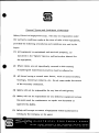
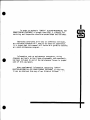
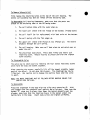
In order to maintain "SAFETY" ELECTRO-MECHANICAL
AIR
CONDITIONING EQUIPMENT in proper condition, a schedule for
servicing and inspection should be established
and followed.
Operating conditions will vary on different railroads,
so a suitable schedule will have to be based on experience.
It is hoped that this manual will serve as a guide to setting
up a good maintenance
program...
Information such as maintenance procedures, wiring
diagrams and tools to facilitate disassembly
and reassembly,
has been included to assist the maintenance
forces in proper
care of this equip_lent.
When supplemental
information concerning "SAFETY"
ELECTRO-MECHANICAL
AIR CONDITIONING
EQUIPMENT is required,
it can be obtained from any of our District Offices...
"SAFETY"COMPONENT
TYPE
INDEX
OF
AIR CONDITIONING
SYSTEM
SECTIONS
PAGE
TITLE
SECTION
I
THE REFRIGERATION
SECTION
II
DESCRIPTION
I.
2.
3.
A.
B.
II-I
OF EQUIPMENT
General
Description
Description
Motor
I.
2.
3.
4.
5.
6.
I-l
CYCLE
of Operation
of Components
II-l
II-l
II-l
MAIN COMPONENTS
II-l
Compressor
Unit - Cat. No. B-3988-4
Adapter Frame - Cat. No. M-5999-3
Compressor - Cat. No. 161705
Compressor Motor - Cat. No. T-18554
Flexible Coupling - Cat. No. 161685
Refrigeration
Controls - Cat. No.B-2899-2
Support Bracket - Cat. No. B-I023
Air Cooled
Condenser
- Cat. No. B-2247-I0
I.
Condenser
2.
3.
Liquid Receiver - Cat. No. M-1782
Condenser Fan and Motor
C.
Evaporator
I.
2.
O.
& Blower
Assembly-Cat.No.
II-2
II-2
II-2
II-2
II-2
II-3
II-3
II-3
II-3
II-3
B-1444-17
II-4
Electric Heat Assembly - Cat. No. B-4319-I
Evaporator Coil Assembly - Cat. No. M-4142-I
II-4
II-4
(a)
(b)
(c)
3.
4.
5.
Coil - Cat. No. B-1566
II-l
Evaporator Coil - Cat. No. B-2488-I
Expansion Valve - Cat. No. T-3695-I
Modulation Control Solenoid Valve T3330-II
Drain Pan - Cat. No. M-1485-I
Flexible Plenum - Cat. No. B-4409
Blower and Motor Assembly - Cat. No. B-1434-15
Motor
Start
and Control
SYSTEM
Panel Assembly
II-4
II-5
II-6
11-6
11-6
II-6
II-7
AUXILIARIES
a.
b.
c.
d.
Moisture and Liquid Indicator
Liquid Line Solenoid Valve
Liquid Line Strainer Assembly
Check Valve
II-7
II-8
II-8
II-9
e.
f.
Liquid Line Filter-Drier
Flexible Tube Line Connectors
II-9
II-9
o
INDEX
OF
SECTIONS
TITLE
SECTION
Ill
III-l
OPERATION
Operating
III-2
Instructions
III-2
III-2
III-3
Initial Starting Check
Starting Instructions
Nominal Operating Data
SECTION
IV
ROUTINE
SERVICE
IV-l
INSTRUCTIONS
IV-l
IV-l
IV-l
IV-l
Weekly Servicing
Monthly Servicing
Annual Inspection
Preparations for Winter
SECTION
V
TROUBLE
DIAGNOSIS
V-I
CHART
High Head Pressure
Low Head Pressure
High Suction Pressure
Low Suction Pressure
Frequent
Noises
Cycling
Compressor is Noisy
Compressor Will Not Start
Cylinders and Crankcase Sweating
Failure to Cool
Air Circulating
SECTION
Vl
MAINTENANCE
I.
Fans Not Operating
AND SERVICE
INSTRUCTIONS
V-I
V-I
V-I
V-2
V-2
V-2
V-3
V-3
V-3
V-4
V-4
VI-l
VI-l
General
al
PAGE
Safety
(I) Importance of Dehydration
(2.)Use of Alcohol
(3) Grease Solvents
(4) Soldered Connections
(B) Opening the System
(6)
Evacuating Air From The System
(7) Testing for Leaks
(B) To Add Refrigerant to the System
VI-l
VI-l
VI-I
Vl-2
VI-2
VI-2
VI-2
VI-3
VI-3
(a) Low Side Charging
(Vapor)
(b) High Side Charging (Liquid)
(g) Removal of Non-Condensable
Gases
(lO) Adding or Removing Oil
Vl-4
VI-4
VI-5
VI-S
(a)
Compressor
ii
Lubrication
VI-5
INDEX
OF
SECTIONS
TITLE
SECTION Vl
MAINTENANCE AND SERVICE
Servicing
the
Motor Assembly
2,
a.
b.
c.
d.
e.
f.
g.
h.
Components
Servicing
Condenser
the
CompressorVl-6
Modulation
b.
(I)
(2)
(3)
Coil
5.
Repairing
6.
Safety
the
Air
VI-15
Cooled
Vl-17
Vl-17
From The
Unit
VI-19
VI-20
VI-20
the Motor
the Motor
VI-21
Pump Down
To Remove Refrigerant
To Remove Receiver
To Replace
Receiver
Coil
of
the
Vl-21
VI-22
VI-23
VI-24
Evaporator
and
VI-25
Assembly
Evaporator
Coil
(a)
To Remove
Expansion
Valves
Evaporator
Coil
Blower
Motor
(a)
Maintenance
(b)
To Remove
(c_
To Remove
the
VI-25
Coil
Assembly
Modulating
the
the
Motor
Blower
Solenoid
Valve
Wheels
Leaks
Precautions
VI-17
Vl-17
VI-18
VI-19
Receiver
Evaporator
(2)
(3)
(4)
Switch
Maintenance
Servicing
Components
Blower
Assembly
(I)
of
Vl-12
VI-12
VI-13
VI-14
VI-15
Fan Motor
Maintenance
To Remove
To Replace
Liquid
(I)
(2)
(3)
(4)
Vl-6
VI-6
VI-7
VI-7
VI-7
Vl-8
VI-12
To Clean the Condenser
Coil
To Remove the Condenser
Coil
To Replace
the Condener
Coil
Condenser
c,
Control
the Components
Assembly
Condenser
(I)
(2)
(3)
a.
of
(continued)
Description
(a)
Selector
Switch
(b)
Gauge and Valve Assembly
(c)
Dual Pressure
Control
Adjustments
(d)
Repairs
Pressure
a.
4.
INSTRUCTIONS
To Remove the Motor
To Remove the Compressor
To Replace
the Compressor
Compressor
Compressor
Service
Valves
Flexible
Coupling
Alignment
Refrigeration
Controls
Assembly
(I)
,
PAGE
VI-25
VI-25
VI-26
VI-29
VI-29
VI-29
VI-29
VI-30
VI-30
in
iii
Handling
Refrigerant
12
VI-33
INDEX OF SECTIONS
PAGE
TITLE
SECTION
Vll
VII-l
AIR CONDITIONING
STARTER
PANEL
Air Conditioning
Starter
Panel
Operation
VII-l
Air Conditioning
Starter
Panel
Troubleshooting
VII-2
iv
LIST
OF ILLUSTRATIONS
TITLE
SECTION
I
THE REFRIGERATION
Table
I-I
Physical
Figure
l-I
Diagram
SECTION II
CYCLE
Properties
of Refrigerant
of the Refrigeration
DESCRIPTION
II-I
Motor
Figure
11-2
Air Cooled
Condenser
Figure
11-3
Evaporator
& Blower
Compressor
III
OPERATION
Table
III-I
Pressure
Control
Table
111-2
Operating
Data
SECTION VI
I-2
12
I-3
Cycle
OF EQUIPMENT
Figure
SECTION
PAGE
MAINTENANCE
Unit
(Type
Unit
II-ll
(Type B-2447)
Assembly
Switch
II-lO
B-3988)
(Type B-1444)
III-2
Settings
(Nominal)
AND SERVICE
II-12
III-3
INSTRUCTIONS
Figure VI-]
Compressor
Figure Vl-2
Flexible
Coupling
VI-8
Figure
Flexible
(Caliper
Coupling Alignment
and Straight Edge)
Vl-lO
Coupling
VI-3
Service
VI-8
Valve
Figure
VI-4
Flexible
Figure
VI-5
Refrigeration
Figure
VI-6
Range and Differential Adjustment
Pressure Control Switch
Figure
VI-7
Wiring
Figure
VI-8
Pressure
Alignment
Control
Diagram
(Alignment
Modulation
Control
Vl-ll
_I-12
Assembly
- Refrigeration
Gauge)
-
Controls
Switch
VI-13
VI-15
VI-16
F_gure VI-9
Condenser
Fan Motor
VI-19
Figure Vl-IO
Expansion
Valve
VI-28
V
APPENDIX
FIGURE
DIAGRAMS
Schematic
- Refrigerant
Schematic
- Wiring
l
Flow - MSK-2396
Diagram
2
- B-4302
FORM NO.
PARTS LISTS
Air
Cooled
Condenser
Direct
Condenser
Fan Motor
Driven
Motor
Evaporator
& Blower
-
Fan Motor
Flexible
-
Cat,
Cat.
Assembly
-
Coupling
Cat.
-
No. B-2447
type
Unit
-
Cat.
No.
B-3988
Cat,
No.
Cat.
No.
5775
B-1444-17
5784
Motor
and Control
5310-A
161685
Assembly
Panel
5776
5782
T-18554
-
5777
5783
No. T-16807-I
Controls
Starter
Cat.
No. T-16822
No.
Refrigeration
SERVICE
-
Motor-Compressor
Compressor
Blower
Assembly
-
Cat.
No.
B-2899
type
-
Cat.
No.
B-4290-1
5310-A
5779
INSTRUCTIONS AND PARTS LIST
Compressor
I.
2.
3.
-
Cat.
5297
161705
Servicing
the Compressor
Capacity
Control
for Unloading
Parts
List
Service
Manifold
Solenoid
Valve
Filter-Drier
Instructions
in Blast
Rubber
No.
Gauge Assembly
-
Cat.
No,
Assembly
-
for Field
Coil
Heaters
Bladed
Fan -
Cat.
-
Compressor
Cat,
No.
5285
T-12497
5453-A
T-3330-II
Cat.
No.
5287-A
163088
Replacement
of
Resistance
Coils
5634
No.
M-3897-4
vi
5778
SECTION
1.
THE
REFRIGERATION
CYCLE
SECTION
THE
REFRIGERATION
1
CYCLE
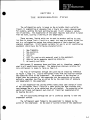
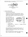
The refrigeration cycle is based on the principle that a volatile
liquid, in evaporating or changing from a liquid to a vapor, absorbs heat.
For example, wetting the hand and blowing upon it will produce a sensation of coolness.
The evaporation of the water requires heat which is taken
from the hand, causing a lowering of the temperature.
There are many liquids which can be used to produce cooling
ing them to change from a liquid to a vapor, but some are better
by caussuited for
use in a refrigerating
system than others because of their physical and
chemical properties.
A refrigerant suitable for use in an air conditioning
equipment should have the following characteristics:
I.
2.
3.
4.
5.
6.
7.
Non-flammable.
Non-explosive.
tlon-toxic
Stable.
l,_ustnot combine with material used in the equipment.
Require low or moderate operating pressures.
Be readily available.
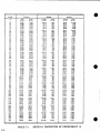
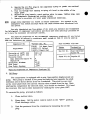
Refrigerant 12 possesses these qualities and is, therefore, commonly
used in air conditioning systems.
The temperature pressure relation for
this refrigerant is shown in Table on Page I-2.
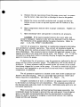
The flow of refrigerant through the cycle may be traced by reference
to Figure 1, Page I-3. Liquid refrigerant flows from the receiver through
the expansion valve to the evaporator.
The pressure in the receiver is
higher than the pressure in the evaporator and the expansion valve automatically regulates the flow as called for by the conditions of pressure
and temperature in the evaporator.
In the evaporator the cooling effect takes place upon change of state
of the refrigerant from a liquid to a vapor during the heat transfer process between the air to be cooled and the refrigerant.
The expansion valve
admits sufficient refrigerant such that all liquid has evaporated prior
to leaving the coil.
The air circulating
evaporator surface.
through
the car is cooled
by passing
it over the
The refrigerant vapor formed in the evaporator is removed by the
action of the compressor.
On the down or suction stroke of the compressor
I-I
Pressure
Tcm_.
I;>SqlitT
*F.
I0
12
|4
16
18
29.35
30.56
31.80
33.08
34.40
14.65
15.86
17.10
18.38
19.70
0.0112
,0112
.0112
.0112
.0113
1.351
1.301
1.253
1.207
1.163
89.45
89.24
89.03
88.81
88.58
0,7402
.7687
.7981
.8288
,8598
20
22
24
26
28
35.75
37.15
38.58
40.07
41.59
21.05
22.45
23.88
2_,.37
26.89
0.0113
.0113
.0113
.0114
,0114
1.121
1.081
1.043
1.007
0,973
88.37
88.13
87.91
87.68
87.47
0.8921
.9281
.9588
.9930
1.028
3O
32
34
36
38
43.16
44.77
46.42
48.13
49.88
28,46
30,07
31.72
33.43
35.18
0.0115
.0115
.0115
,0116
.0116
0.939
.908
.877
.848
.819
87.24
87.02
86.78
86.55
86,33
1.065
1.102
1.140
1.180
1.221
40
42
44
46
48
51.68
53.51
55.40
57.35
59.35
36.98
38.81
40.70
42.65
44.65
0,0116
.0116
.0117
.0117
.0117
0.792
.767
.742
.718
.695
86.10
85.88
85.66
85.43
85.19
1.263
1.304
1.349
1.393
1.438
50
52
54
56
58
61.39
63.49
65.63
67.84
70,10
46.69
48.79
50.93
53.14
55.40
0.0118
.Ol 18
.0118
.0119
.0119
0.673
.652
.632
.612
.593
84.94
84.71
84.50
84.28
84.04
1.485
1.534
1.583
1.633
1.686
60
82
64
66
68
72.41
74.77
77.20
79.67
82.24
57.71
60.07
62.50
64.97
67.54
0.0119
.0120
.0120
.0120
.0121
0.575
.557
.540
.524
.508
83.78
83.57
83.34
83.10
82.86
1.740
1.795
1.851
1.909
1.968
70
72
74
76
76
54.82
87.50
90.20
93,00
95.85
70.12
72.80
75.50
78.30
81.15
0.0121
.0121
.0122
.0122
.0123
0.493
.479
.464
.451
,438
82.60
82.37
82.12
81.87
81.62
2.028
2,090
2.158
2.218
2.284
60
82
84
88
65
98.76
101.7
104.6
107.9
I 1 I_ 1
84.06
87.00
90.1
93.2
96,4
0.0123
,0123
.0124
.0124
.0124
0.425
.413
,401
.389
.378
81.39
81.12
80.87
80.63
80.37
2.353
2.423
2.495
2.569
2,645
90
92
94
96
98
114.3
117.7
121.0
124.5
128,0
99.6
103.0
106,3
109.8
113.3
0.0125
.0125
.0126
.0126
,012(_
0.368
.357
.347
.338
,328
80.11
79.86
79.60
79.32
79.06
2.721
2,799
2.880
2.963
3.048
I00
102
104
106
108
131.6
135.3
139.0
142.8
146.8
116.9
120.6
124.3
128.1
132.1
0.0127
,0127
.0128
0.319
,310
.302
t0128
.0129
.293
.285
78.80
78.54
78.27
78.00
77.73
3.135
3.224
3.316
3.411
3.509
I10
112
114
116
118
150,7
154.0
158.9
163.1
167.4
136,0
140.1
144.2
148.4
152.7
8.0129
.0130
.0130
.0131
.0131
0.277
.269
.262
.254
.247
77.46
77.18
76,89
76.60
76.32
3.610
3.714
3,823
3.934
4.049
120
122
124
126
128
171.8
176.2
180.8
185.4
190:1
157.1
161,5
166.1
170,7
175,4
0.0132
.0132
.0133
.0133
.0134
0.240
.233
.227
.220
.214
76.02
75.72
75.40
75.10
74.78
4.167
4.288
4.413
4.541
4.673
130
132
134
136
138
194.9
199.8
204,8
209.9
215.0
180,2
185.1
190.1
195.2
200.3
0,0134
.0135
.0135
.0136
.0137
0.208
.202
.196
.191
.185
74.46
74.13
73.81
73.46
73.10
4.808
4.948
5,094
5.247
8.409
140
220.2
205.5'
0.0138
0.180
72.73
8.$71
TABLE
I-2
Voluml
Abs.
ib./in.Z
I-1
Ca|e
Ib./inJ
Liquid
f t.I/Ib,
Vapor
ft. J/lb.
Liquid
Ib./11.)
PHYSICAL
PROPERTIES
OF
Vapor
lb./ft.
REFRIGERANT
I
12
piston, the cylinder is filled with vapor and on the up or discharge
stroke, this vapor is compressed and discharged into the condenser.
As
the pressure is increased, the temperature likewise is raised due to the
work done on vapor by the compressor.
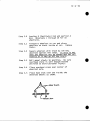
The process which takes place in the condenser is the reverse of
that in the evaporator.
In the latter, heat is ADDED to the liquid,
causing it to vaporize.
In the condenser, heat is ABSTRACTED from the
vapor causing it to condense to the liquid state.
This heat is removed
by passing outside air over the condenser surface.
COLD
LIQUID
REFRIOERANT
¢OOL
EX_NeJON_LVE
(HOT
GAS)
;0MPRESSOR
HOT
LIQUID
3[RANT
(HOT
FIGURE
LIQUID)
I-I
RECEIVER
DIAGRAM
OF
REFRIGERATION
CYCLE
I-3
SECTION 2
DESCRIPTION
SECTION
DESCRIPTION
.
OF EQUIPMENT
2
OF EQUIPMENT
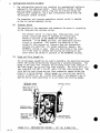
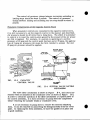
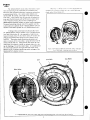
GENERAL
The "Safety" component type 8-ton (Refrigerant 12) electromechanical
system consists of a separately mounted Motor-Compressor
Unit, and a
Condenser Unit applied underframe, together with an Evaporator and
Blower Assembly which is mounted above the ceiling area at one end of
the car.
The motors are arranged for operation on 460/3/60 power
supply and a control voltage of 120/I/60 hz.
MAIN COMPONENTS
2.
CAT. NO.
I.
Motor Compressor
2.
Air Cooled
Condenser
3.
Evaporator
and Blower
4.
Motor Control
DESCRIPTION
B-3988-4
Unit
Panel
Unit
Assembly
B-2247-I0
B-1444-17
B-4290-I
OF OPERATION
To deliver conditioned
air to the interior of the car body, a mixture
of recirculated
air, (returned from the car body) and outside air is
filtered, passed through the evaporator and electric heat surfaces by
the blower fans and discharged into the overhead centerline air distribution duct.
By absorbing heat taken from the air, the liquid refrigerant from the receiver is vaporized in the evaporator.
This cools and
conditions the leaving air which is then ducted into the car body.
The refrigerant vapor leaving the evaporator is returned
sor where it is forced to higher temperature and pressure
discharged into the condenser.
This compressed vapor is
in thecondenser
by drawing outside air through the coil
liquid refrigerant returns to the receiver and the cycle
3.
DESCRIPTION
to the compreslevels and
then liquified
surface.
The
is repeated.
OF COMPONENTS
MAIN COMPONENTS
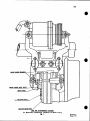
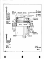
A.
Motor-Compressor
Unit - Cat. No. B-3988-4
Included in this unit are an adapter frame, compressor, motor,
flexible coupling, refrigeration
controls, and supporting bracket.
The motor is flanged mounted to the bracket which holds the compressor to form a rigid unit as shown in Figure II-l.
The assembly is isolated from the underframe support members by resilient
mounts.
II-I
I.
Adapter Frame - Cat. No. M-5999-3
The adapter frame is a rugged steel weldment which is secured
to the undercar support membersto provide the mounting structure for the resiliently
mounted motor and compressor assend)ly.
2.
Compressor
- Cat. No. 161705
The compressor is a Carrier manufactured
four cylinder, air cooled,
open, "Vee-type", with forced feed lubrication and is powered by
an external driving motor.
To match the requirements of the system, variations in capacity
are obtained by the operation of a built-in cylinder control
mechanism.
Power for this control unit to load or unload three
cylinders in sequence is obtained hydraulically
from the forced
feed lubrication system in response to changes in the suction
pressure.
The principles of operation and maintenance procedures for the
compressor equipped with capacity control mechanism are included
in the Appendix, Form 5297.
3.
Compressor
Motor - Cat. No. T-18554
The compressor motor operates on 460/3/60 hz power, is a NEMA
D-flange type, totally enclosed fan cooled, frame size 254T, and
is rated 15 horsepower at 1760 RPM.
Class "B" insulation is used
and the design full load power is approximately
13 HP.
4.
Flexible
Coupling
- Cat. No. 161685
Torque is transmitted to the compressor through a flexible coupling designed for high speed operation and heavy duty service.
The stainless steel laminated disc assembly is torsionally rigid
to prevent damage due to backlash and also provides for free end
float of both connecting shafts.
5.
Refrigeration
Controls
- Cat. No. B-2899-2
The refrigeration
controls are installed in a weatherproof
box
attached to the support frame.
These controls include a dual
pressurestat having high and low pressure control switches, discharge and suction pressure gauges,.and a three position selector
switch for MANUAL-OFF-AUTOMATIC
operation of the equipment.
Gauge
lines are equipped with shut off valves which should be opened
only to determine operating pressure in the system.
In the MANUAL
position, the temperature control circuit is by-passed.
This permits the operation of the equipment for test purposes at intervals
when the thermostatic controls are satisfied.
For normal operation,
the AUTOMATIC setting should be used.
When the cover of the control
box is closed, the selector switch is positioned to the AUTOMATIC
position.
11-2
6.
Support
Bracket
- Cat. No. B-I023
The compressor bracket support is designed for the severe impact
and shock loads experienced
in railroad service.
Thils unit is of
all welded steel construction with a removable strut member to
provide greater accessibility
to service the compressor.
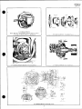
B.
Air Cooled
Condenser
- Cat. No. B-2247-I0
The air cooled condenser shown in Figure II-2 consists of a condenser
coil mounted in an all welded support frame,
liquid receiver, integrally
mounted motor with direct connected axial flow fan, and a pressure modulation control switch.
The assembly is resiliently hung underframe from
the car support members.
I.
Condenser
Coil - Cat. No. B-1566
The coil is arranged for counterflow of refrigerant and the cooling
medium.
A heavy duty all steel six blade axial flow fan which operates in a venturi for high efficiency draws the air through the coil
surface.
An expanded metal guard protects the coil inlet face from flying road
ballast, and a removable hot dipped galvanized fan guard is provided
at the fan discharge.
Superheated
refrigerant vapor from the compressor enters near the
top of the coil and the liquified subcooled refrigerant flows to
the receiver.
2.
Liquid
Receiver
- Cat. No. M-1782
The liquid receiver is mounted vertically
consists of a welded steel shell with two
glasses, liquid inlet and outlet shut off
and purge valve (I/4" OD flare).
This is
to insure that l._quid is not stored above
and outlet valves are closed.
on the supporting frame and
dished heads, two sight
valves (5/8" OD flare),
also used as a test valve
this point when both inlet
A I/4" OD flare connection is provided as an integral part of the
receiver outlet valve for charging the system with liquid refrigerant.
This is a backseating
type valve and, in the fully open position,
the charging port i_sclosed.
3.
Condenser
Fan and Motor
The condenser fan, Cat. No. M-1890-2, is driven by a 2 HP, 1725 RPM,
totally enclosed, 145T frame size motor arranged for 460/3/60 hz
power supply.
The design load for this motor_ Cat. No. T-16822, is
approximately
1.3 HP.
The compressor
taneously.
and condenser
fan motor
must start
and stop simul-
II-3
C.
Evaporator
and Blower
To deliver
conditioned
air
duct,
the evaporator
components:
I.
20 KW Electric
(2)
Evaporator
(3)
Drain
to
(4)
Flexible
(5)
Blower
Heat
Coil
Cat.
the
No.
overhead
assembly
B-1444-17
centerline
includes
distribution
the
following
Assembly
Assembly
with
Associated
Piping
Pan
Plenum
and Motor
Heat
The overhead
the evaporator
rosion-proof
2.
-
and blower
(I)
Electric
Assembly
Assembly
Assembly
-
Cat.
No.
B-4319-I
electric
heat assembly
is mounted
down stream
of
coil
assembly.
It is an open design
type
(corbare wire
elements
with
ceramic
insulators.)
(a)
The overhead
heat is arranged
for two stage
operation
of
I0 KW each at 460/3/60
hz power supply.
Each stage
is
spread
out over the entire
air
path.
The heater
elements
will
not be damaged by sustained
operation
at + 10% rated
voltage
swings.
(b)
To provide
protection
against
excessive
heat build
up, loss
of air,
etc.,
a single
pole,
single
throw
N.C. thermoswitch
(set
to eden at 200°F and with
an automatic
reset
of 185 ° )
is mounted
atthe
top of the casing.
The switch,
Cat. No.
T-14045,
has a silicone
rubber
overmold,
is preset,
nonadjustable,
and not field
serviceable.
This
thermoswitch
operates
a shunt
trip
circuit
breaker.
The N.O. contacts
are in series
with
a shunt
coil
which
is physically
a part
of the circuit
breaker
feeding
the overhead
heatassembly.
With a rising
temperature
caused by loss of air
and, should
the heat contactor
remain
closed
for any reason,
the thermoswitch
contacts
will
close
as the internal
temperature
passes
the set point.
This then energizes
the shunt
coil
in the
circuit
breaker
which
causes an immediate
trip,
thus shutting
down power to the overhead
electric
heat assembly.
To reestablish
power to the heater
assembly,
the circuit
breaker
must
be reset.
Evaporator
Coil
Assembly
-
Cat.
No.M-4142-1
The evaporator coil, Cat. No. B-2488-I, is a six row 3/8" OD
copper tube coil with extended surface of .OlO" copper plate
fins spaced eight to the inch.
11-4
(a)
The coil is divided horizontally into two halves for
modulated control when other than full cooling is required.
Each section is multi-circuited
and fed by an
expansion valve which consists of a power assembly cage,
and valve body.
The valve power assembly is equipped
with a thermal bulb which is securely attached to the
suction line header fed by the valve.
(b)
Expansion
Valves
- Cat. No. T-3695-I
The two expansion valves are located at the side of the
evaporator assembly.
They feed liquid refrigerant to
the two multi-circuited
sections of the evaporator coil.
See Parts List 5775 in the Appendix.
Each expansion valve
has a liquid distributor,
I/4" SAE external equalizer connection, and an external superheat adjusting stem.
NOTE;
In service, the equalizer line must always be
connected to the suction header fed by the valve
to sense the suction pressure leaving the coil,
otherwise, the valve may flood, starve, or regulate the flow of refrigerant erratically.
The expansion valves are operated by the pressure differential between the suction pressure in the evaporator and
the pressure in the thermostatic charge of the thermal
bulb.
Since the thermal (feeler) bulb is in thermal contact with the suction line, the pressure in the bulb is
a function of the suction line temperature.
Since the
valve operates on a pressure differential,
it cannot be
set to produce a fixed evaporator pressure.
After the evaporation of the liquid refrigerant
in the
evaporator,
the suction vapor is superheated and its
temperature will increase.
However, the evaporator pressure, neglecting the pressure drop, is unchanged,
The
warmer vapor flowing through the suction line increases
the bulb temperature.
Since the thermal bulb contains
both a liquid and vapor charge, the temperature and pressure will increase.
The higher bulb pressure causes the
valve to open and admit more refrigerant to the evaporator.
Conversely,
if the valve feeds too much refrigerant, the
bulb temperature is decreased, or the evaporator pressure
is increased, to cause the valve to close and adjust to the
new load condition.
II-5
(c)
Modulation
Control
Solenoid
Valve
- Cat. No. T-3330-II
For capacity reduction, the admission of refrigerant to
the top evaporator circuit is controlled by a normally
closed solenoid valve (with 120/I/60 coil, Cat. No.
T-7820-4) which responds to the temperature modulation
thermostat.
To open the valve manually in the event of failure of
the coil, a side adjusting stem opens a by-pass for
liquid refrigerant.
To open the valve manually, the stem
must be turned a maximum of one-half revolution counterclockwise.
Under normal service conditions, the manual
opening stem is positioned to the closed setting.
3.
Drain Pan - Cat. No. M-1485-I
A stainless steel drain pan extends under the evaporator coil and
electric heat assemblies to collect condensate which is formed
on the evaporator coil surface.
The pan is pitched to drain to
the back edge where two copper tube lines are connected.
The exterior of the pan is insulated to prevent condensation of
the cold surface.
A premolded vinyl plastic insulation with a
minimum thickness of I/4" is applied to the outside surface.
Baffles and splash angles are provided within the pan to prevent
condensate from spilling over on grades or during periods of
acceleration or deceleration.
4.
Flexible
Plenum - Cat. No. B-4409
A fire resistant and water-proof
flexible duct of neoprene covered
glass fiber is provided between the fan and motor assembly and
the evaporator.
This duct may be detached easily to permit _ccess
to the coil surface for cleaning and inspection.
5.
Blower
and Motor Assembly
- Cat. No. B-1434-15
The blower motor assembly is resisiently mounted to overhead car
support members.
The assembly is rated 2400 CFM at 1.25" wg TSP
and includes:
two forward curved, double width, double inlet
(DWDI) centrifugal blower wheels which are flange mounted to shaft
extensions on a 182T frame size, one horsepower motor.
The motor, Cat. No. T-16807-I, is open, drip-proof, equipped with
sealed bearings for normal service life and will operate at 1725 RPI4
on a 460/3/60 hz power supply.
After uncoupling the mating flanges for the shaft extensions to
which the blower wheels are applied, the motor may be lowered
by removing four mounting bolts.
II-6
D.
Motor
Start
and Control
Panel
Assembly
The motor control
panel
contain_
compressor
motor,
condenser
fan
heat assembly
and the essential
-
Cat.
the components
for starting
the
motor,
blower
fan motor and electric
overload
protective
devices.
The panel
is arranged
so that
any
ration
may be serviced
or replaced
panel
from the electrical
locker.
component
from the
SYSTEM AUXILIARIES
The Refrigerant
schematically
in the liquid
a.
Moisture
Flow Diagram,
MSK-2396,
the various
system optional
refrigerant
lines.
and Liquid
No. B-4290-I
Indicator_
subject
to wear or deteriofront
without
removing
the
(Optional)
Figure
1 in
auxiliaries
the Appendix
which are
lists
piped
Cat. No. T-15521-2.
This assembly is installed in the liquid line to the evaporator section immediately ahead of the expansion valves.
This indicator shows
the adequacy of the refrigerant charge as well as the quality or
relative dryness of the liquid in the system•
The indicator element
is highly sensitive to moisture and will gradually change color in
direct relation to an increase or decrease in the moisture content
of the system•
The dry-caution-wet
system operating conditions are
then easily determined by matching the element color with the four
colors displayed on the reference label.
Colors vary as often as the
moisture content in the system changes.
An unsafe (wet) indication
would call for replacement of filter-drier cores.
The indicator element before installation will indicate an unsafe
condition.
This is normal and simply reflects the room humidity
condition.
Also, LIQUID refrigerant must be in contact with the
indicator element, with the system in operation, to insure a positive
and true color reading.
The fused g lass
eyepiece
in the indicator provides a clear wide angle
•
*
i
view of the llquld refrlgerant flow so that bubbles or flash gas may
be L,asily seen.
This condition indicates an insufficient system
charge, low discharge (head) pressure, insufficient liquid subcooling
or some form of restriction in the liquid line.
Low discharge pressure will occur when reduced cooling load demands prevail or low outside ambient conditions prevent the build up of the high side pressure
in the condenser.
Thus the discharge pressure must be at least 180 psig and 37 psig
suction before the determination of low charge of refrigerant is
made. Following installation of the moisture and liquid indicator or
filter-drier cores, the system should be allowed to reach equilibrium
after a minimum of twelve (12) hours operation before attempting to
determine safely the moisture content in the system.
If a caution
or unsafe condition is still indicated following this period, the
filter-drier core assembly must be replaced.
This practice should
be continued until the system is dry and a safe condition is indicated.
II-7
b.
Line
Solenoid
Valve
-
Cat.
No. T-3330-II
A normally
closed
solenoid
valve
is located
in the main liquid
line
to the evaporator
and also
in the coil
modulation
(top)
circuit.
These valves
are also
equipped
with
a manual opening
stem which
serves
as a liquid
by-pass
so that
the system may
continue
to operate
in the event
of failure
of the coil.
To
open the valve
manually,
the stem must be turned
counterclockwise a maximum of one-half
revolution.
For normal
system operation,
the valve
must be operated
with
the manual stem in the
closed
position.
The system does not require
pump down operation
but since
the
quantity
and location
of the refrigerant
within
the system piping cannot
be definitely
controlled,
the main line
solenoid,
along
with
the check valve
in the compressor
discharge
line,
will
stop the migration
of refrigerant
after
shut down.
In
this
way oil
dilution
and carry
off
from the compressor
are
avoided.
In service,
advance of
c.
the line
compressor
solenoid
valve
start
up.
opens
ten
Refer
to Form 5453-A in the Appendix
ment parts
and service
instructions.
for
Liquid
No. T-15531
Line
Strainer
Assembly
-
Cat.
the
(I0)
list
seconds
of
in
replace-
A cleanable
"Y" type forged
brass
strainer
with
5/8"
ODF solder
end connections
contains
a replaceable
monel screen
#80 mesh
size with
a screw clean
out plug.
A 44 micron
(#325)
mesh
"cleanup"
screen
is installed
in the liquid
line
strainer
for
use
during
the first
6 - lO hours of operational
tests
to collect
and
remove any foreign
contaminants
from the system piping.
However,
the standard
#8_mesh
screen,
Cat. No. T-15532-I,
is applied
prior
to the release
of the car to service
operation.
Shutoff
isolate
replaced.
valves
are provided
at
the refrigerant
charge
the inlet
when the
and outlet
connections
monel screen
is cleaned
to
or
To clean
or replace
the screen,
isolate
the refrigerant
charge
by
pumping down the system.
Close
the inlet
valve
at the assembly
and operate
the compressor
until
the suction
pressure
is approximately
2 psig.
Close the outlet
valve.
Set the selector
switch
to the OFF position.
Loosen the strainer
screw
plug slowly
to
relieve
residual
line
pressure.
USE CAUTION TO PREVENT INJURY TO
THE EYES, FACE, AND HANDS.
Unscrew
the plug and remove the screen
nested
within
the recess.
Wash the screen
in a clean
solvent.
(Do
not use carbon
tetrachloride.)
Dry the screen
thoroughly
and insert
the non-reinforced
end within
the recess
in the plug.
Replace
the
plug loosely
and open the inlet
valve
at the assembly
momentarily
to purge the line.
Tighten
the cap and test
for leaks.
Open the
inlet
and outlet
valves.
11-8
d.
Check
Valve
-
Cat.
No.
T-14691-I
A check valve
is installed
in the discharge
line
between
the
compressor
and condenser
coil.
This
is to insure
that
refrigerant
entrained
in the high
side of the system is not permitted
to return
to the compressor
during
periods
of shut down.
e.
Liquid
Line
Filter
Drier
-
Cat.
No.
163088
A filter-drier
of the replaceable
core type
is mounted
in the
liquid
line
at the outlet
of the receiver.
Its purpose
is to
filter
out particles
in the piping
system
(copper,
solder,
dirt)
and to retain
any moisture
left
in the system at installation
or introduced
while
servicing.
Valves
are provided
that
the two cores,
opening
the entire
The procedure
for
replacement
parts
f.
Flexible
Line
at the inlet
and outlet
of the assembly
Cat. No. 163089,
may be replaced
without
system.
renewing
the
is described
core assembly
and the
on Form 5287-A in the
so
list
of
Appendix:
Connectors
The refrigerant
liquid,
suction,
and discharge
lines
at the
resilient
mounted
condenser
and compressor
assemblies
are
equipped
with
neoprene
jacketed
flexible
tube connectors.
These
are a mechanical
bellows
type with
neoprene
coverings
over the
flexible
seamless
bronze
hose and bronze wire
braid
to provide
resistance
to abrasion,
and to prevent
condensation
and moisture
from freezing
behind
the ferrules.
11-9
I
SUCTION VALVE
W/LOW SIDE CHARGING
CONNECTION (VAPOR)
RESILIENT
MOUNTS
(4) "'-'"-_,,_.--_"_._._.7 --_-_
DI SCIIARGE VALVE
,IJ
FLEXIBLE
COF_TROLSASSEMBLY
_II-LOW PRESSURE CONTROL __l_Cil
COUPLING
COMPRESSOR
SUPPORT
FR_IE
5ELECTOR
REMOVABLE
STRUT
FIGURE
Type B-3988
II-l
Less Unit Adapter
MOTOR-COMPRESSOR
and Undercar
ASSEMBLIES
---SUCTIOII(LOW)SIDE CONNECTION
(AS A VAPOR)
DISCIIARGE(IIIGII)SI[_E - PURGE
ASSEMBLY
Mountin 9 Support
SWITCH
Frame
CON_.
RESILIENT
MOUNTS
CONDENSER
SUPPORT
COIL
FRAME
RECEIVER
_'_'INLET
PURGE
VALVE
VALVE
,SIGHT GLASS
(2)
OUTLET VALVE
_UID REFRIGERANT
CHARGING CONNECTION)
PRESSURE
MODULATION
MOTOR
FAN GUARD
ACCESS
DOOR
TYPE B-2447
I
FIGURE
II-2 AIR COOLED
LESS UNIT ADAPTER
CONDENSER
AND UNDERCAR
UNIT
MOUNTING
SUPPORT
FRAME
CONTROL
SWITCH
EXPANSION
VALVES
EVAPORATOR
MODULATION
SOLENOID
VALVE
RESILIENT MOUNTS
FLEXIBLE
SUPPORT
PLENUM
It
BLOWER AND MOTOR
ASSEMBLY
.
LIQUID LINE
CONNECTION
HEATING
COIL
DRIP
PAN
EVAPORATOR
COIL
MOTOR
FAN
SUCTION LINE CONNECTION
FIGURE
H-3
EVAPORATOR
AND
TYPE
11-12
BLOWER
B-1444
UNIT
SECTION
3
OPERATION
SECTION
0 PE
With
all circuit
breakers
RAT
arranged
3
I0 N
in the "ON" position,
switches
closed, and the compressor motor control switch in the AUTOMATIC setting,
the control circuit is energized.
This permits current flowing to the
evaporator blower motor circuit to operate the air circulating fans in the
overhead unit.
The system is now capable of automatic functioning in
either the full or modulated cooling cycles to satisfy the given load conditions.
The operation of the controls is described in Section 7 and also
illustrated
schematically
in the wiring
diagram,
Figure
2 in the Appendix.
If the car body temperature is above the high thermostat setting and
calls for full cooling, the compressor motor and condenser fan motor will
start.
The system then operates at rated capacity, that is, with all
cylinders of the compressor loaded and pumping and both sections of the
evaporator coil in use.
Also,
I.
2.
3.
the:
Evaporator
Compressor
Evaporator
Blower Motor is operating.
Motor and Condenser Fan Motor run.
modulating solenoid valve is energized
(open).
This mode of operation continues until the car body temperature is
reduced to the setting of the high thermostat.
The controls then function
to reduce the cooling capacity.
During this modulated operation as the
evaporator solenoid valve closes the compressor automatically
unloads in
response to the lowering of the suction pressure.
The functioning of the
unloading compressor with pressure type capacity control mechanism is contained in the Appendix, Form 5297.
If the car temperature continues to fall to the setting of the low
thermostat, the controls function to stop operation.
The condition of the
equipment then is:
I.
2.
3.
Evaporator
Compressor
Evaporator
Blower Fan Motor is operating.
Motor and Condenser Fan Motor are stopped.
modulation solenoid valve is closed.
This arrangement provides for the automatic adjusting
capacity to approximate the cooling load requirements.
of the system
It should be noted that the conditions under which the equipment is
called upon to operate are not constant.
Together with changes in the outside temperature, the internal cooling load varies with the temperature and
the number of passengers.
This combination of variables affects the operating performance.
Under light cooling loads or low outside temperatures,
the
suction and discharge pressures will also be lower than conditions of heavy
loads when a build-up in operating pressures will be noted.
When the system is not operating, the suction and discharge pressures
will tend to equalize.
The final pressure depends upon the car temperature
and the outside temperature.
III-l
OPERATING
Initial
INSTRUCTIONS
Startin 9 Check:
I.
Check oil level in compressor
sight glass.
sight
2.
Check all electrical
for tight connections•
3.
Refrigerant lines should
leak detector torch.
4.
Open and backseat
valves.
5.
Open
Starting
l
•
o
.
4.
•
circuits
be checked
the compressor
the inlet and outlet
glass.
for tightness
discharge
using
and suction
be I/2
a Halide
shut off
valves at the receiver.
Instructions:
Arrange the circuit breakers at the temperature control panel to the
"ON" position and close the cooling switch to set the evaporator blower
motor in operation•
To operate the cooling cycle, the compressor motor control switch
should be set to the "Automatic" position.
The equipment will then
operate at rated capacity if the high thermostat setting is exceeded
or at reduced capacity if the low thermostat is in control.
For test
purposes where by-passing the control thermostats is necessary for
operation of the system, the compressor motor selector switch should
be set to the "Manual" position.
It is essential that the condenser fan be arranged for proper rotation.
(Draw through operation).
Since the compressor is equipped with a
gear type positive displacement oil pump, the directional arrow on
the top of the cover plate must be checked.
If the arrow does not
point in the direction of rotation, the oil pump must be reversed
by following the procedure outlined in Form 5297.
Trouble diagnosis
Form 5297•
charts
are given
in Section
5 and,
in the Appendix,
The nominal settings for the high and low pressure controls and the
pressure modulation control switch are provided in the following
table:
Pressure
Control
Switch Type
High Pressure Control
Low Pressure Control
Modulation Pressure Control
TABLE III-I PRESSURE
III-2
This level should
CONTROL
Cut-Out
(Open)
275
2-5
235
SWITCH SETTINGS
Cut-ln
(Closed)
225
12-15
205
Nominal)
NOMINAL OPERATING DATA 460/3/60
hz.
8 TON SYSTEM (REFRIGEP_ANT R-12)
POWER SUPPLY AND 120/I/60
CONTROL VOLTAGE
Evaporator
Cooling
Load ................................
Air Volume .................................
2400
Air
to Condenser
............................................
Suction
Pressure
(at Compressor)
............................
Discharge
Pressure
(at Compressor)
..........................
Compressor
Motor,
15 HP............................
Speed (approximately)
.....................................
Current,
(EL) approximately
..............................
Power (FL)
approximately
.....................................
Condenser
Fan Motor,
2 HP .........................
Speed (approximately)
....................................
Current
(FL) approximately
...............................
Blower
Fan Motor,
1HP .............................
Speed (approximately)
....................................
Current
(approximately)
..................................
Control
Voltage
Nominal
..................................................
Compressor
Discharge
Line Temperature
....................................
Suction
Line Temperature ...........................
Oil
Charg_ ........................................
Oil
Level
In Crankcase
When Operating
(approximately)
When Not Operating ....................
Refrigerant
Level
in Receiver(*)
(*)at
180 psig
Discharge
........
....
Pressure
TABLE 111-2
-
96000 BTU/HR
@ 1.25 ° wg TSP
95°F DB
32 psig
195 psig
460/3/60
hz power
1760 RPM
17 amps
13 HP
460/3/60
hz power
1725 RPM
3.0 amps
460/3/60
hz power
1725 RPM
1.6 amps
cfm
J20/I/60
Hot
Cool - No Frost
12 pints
(U.S.)
Half
Level in
I/3
- 2/3 Sight
Half
Level
in Lower
and 37 psig
Suction
Sight
Glass
Sight
Glass
Level
Glass
Pressure
TABLE OF OPERATING DATA (Nominal)
111-3
SECTION
4
ROUTINE
SERVICE
INSTRUCTIONS
4
SECTION
ROUTINE
More
satisfactory
SERVICE
operation
with
INSTRUCTIONS
fewer
failures will
be obtained
if
the equipment is put in first class condition during prescribed car shopping
periods, by adhering to preventive maintenance schedules, and implementing
systematic service procedures.
Weekly:
I.
Clean air filters,
2.
3.
4.
5.
6.
Check
Check
Check
Clean
Check
7.
Operate unit to check oil and refrigerant levels under steady operating
conditions.
Note any signs of leakage which will be indicated by oil at
the point of leakage.
See Service Instructions for adding oil and refrigerant.
Inspect motor brushes and commutators.
8.
grilles,
and screens.
evaporator blowers and condenser fan for tightness
motor and compressor mounting bolts for tightness.
motor compressor coupling for tightness.
surface of condenser coil.
operation of control panel.
on shafts.
Monthly:
I.
2.
3.
4.
5.
Clean the surface of the evaporator coil.
Flush the drip pan under the evaporator coil.
Clean drain lines to provide for free drainage.
Inspect and, if necessary, clean contacts on motor
Follow all steps outlined for weekly servicing.
control
panel.
Annually:
r i.
, ..,
.,,n,
2.
3.
The equipment should be given a thorough inspection and a complete
check of the controls made prior to seasonal changeovers.
All steps listed for weekly and monthly servicing should be followed.
Inspect all motors.
4.
5.
Thoroughly clean all coil surfaces.
Blow dirt from interior of casing.
CAUTION
Where established maintenance schedules require the pumping down of
the system and the isolation of the refrigerant charge in the receiver, care
should be taken to insure that the top of the liquid level is visible in the
upper sight glass to allow for expansion.
PREPAPJ_TIONS FOR WINTER
Although no special precautions are required during the winter heating
season, the refrigerant circuit should be inspected for le_ks.
Necessary
repairs should be effected in order that positive pressure will be maintained
within the system during the winter shut down period.
IV-I
SECTION
TROUBLE
5
DIAGNOSIS
CHART
SECTION
TROUBLE
5
DIAGNOSIS
CHART
Faulty operation of the system is indicated by very definite symptoms.
These symptoms may be caused by one or more incorrect conditions which
must be eliminated in a step by step process of corrective measures.
The
following chart of symptoms, their causes and corrections, will be of assistance in quickly and efficiently locating faults.
The procedures
to be followed
in making
repairs
are given
in Section
6.
HIGH HEAD PRESSURE
n
Correction:
May be due to:
a.
b.
Air or non-condensable
system.
Insufficient condenser
Co
Dirty condenser.
d.
Too much
e.
Discharge
liquid
gases
in
a. Purge
air.
from the receiver.
b. Clean air screen and the
condenser surface.
c. Clean the condenser
surface.
d. Draw off some of the
liquid.
e. Open the valve.
in the receiver.
valve closed.
LOW HEAD PRESSURE
a.
b.
C,
d.
Liquid refrigerant flooding
from the evaporator.
back
Leaky compressor discharge valve.
Suction valve closed.
Liquid valve on the receiver
closed.
HIGH SUCTION
a.
Overfeeding
valves.
of the expansion
b.
Leaky compressor
c.
Excessive
cooling
suction
valves.
load on system.
a. Examine fastening of
feeler bulbs to suction
lines.
b. Test; if leaking,
c. Open the valve.
d. Open the valve.
replace.
PRESSURE
a.
Check
the bulb attachments.
b. Pump down, remove the cylinder
head, examine the valve discs
or rings; replace if worn.
C.
When pre-cooling car in hot
weather the suction pressure
will be high, but should
gradually decrease as the
car is cooled.
V-l
LOW SUCTION
Maybe
c.
d.
e.
Correction:
due to:
Insufficient
system.
b.
refrigerant
*a.
in
b.
Too much oil circulating in
system.
Suction valve closed.
Liquid valve at the receiver
is closed.
Little or no cooling load on
the evaporator coil
c.
d.
g.
h.
High pressure cut-out switch
incorrectly set.
Low pressure cut-out switch
incorrectly set.
Air circulating fans not
running.
a.
Check
setting
of switch.
b.
Check
setting
of switch.
c.
Thermal bulb on the expansion
valve has lost charge.
d.
Check the fan motor, protective overload devices and connections.
Detach the bulb from the
suction line and hold in
the palm of one hand. With
the other hand grip the
suction line. If flooding
through is observed, the
bulb has not lost its charge.
If no flooding is noticed,
replace valve power element.
Add refrigerant.
Clogged
liquid
g.
h.
Evaporator coil is dirty.
Faulty unloader mechanism.
e.
f.
filter-drier.
FREQUENT
b.
c.
de
*e.
f.
Check the liquid level in
the lower receiver sight
glass; add refrigerant if
necessary.
Check for too much oil; remove some if necessary.
Open the valve.
Open the valve.
This will occur if the air
circulating fan is not
operating.
Pump down and apply new
filter-drier core.
Clean the coil.
Apply new unloader control unit.
f.
a.
PRESSURE
Insufficient refrigerant
system.
Suction valve or liquid
valve closed.
CYCLING
*e.
in
f.
Open
the valves.
Align the motor with housings.
Tighten.
Check the refrigerant flow
and level in lower receiver
NOISES
a.
b.
c.
Fan striking housing.
Ticking or rattling,loose bolts
Hissing - at expansion valves.
a.
b.
c.
d.
Bearing noise - worn motor
bearings.
Rattle - inadequately supported
piping, loose unit covers.
d.
sight glass.
Replace bearings.
e.
Tighten.
e.
V-2
ii
C_PRESSOR
IS NOISY
Ma_ be due to:
Correction:
a.
Vibration.
a.
b.
Too much oil
C.
do
in circulation.
b.
Slugging due to the expansion
valves feeding too much
refrigerant.
c.
Wear of parts, such as pistons,
pins, bearings, etc.
d.
COMPRESSOR
a.
Thermostat
b.
Overload protective device
tripped. Switches open.
High-pressure
cut-out switch
open.
c.
Low-pressure
e.
Dirty contacts.
f.
Cooling
hl
WILL
cause.
Repair or replace
the compressor.
NOlL START
set too low.
do
cut-out
control
a.
switch
f.
Equipment will operate only
on manual setting of compressor control switch if
car temperature is below
thermostat setting.
Reset overload protective
device and close switches.
Check the setting of the
switch and adjust if
necessary.
Check the setting of the
switch and adjust if necessary.
Check and clean the contacts
on all switches.
Turn to the ON position.
h.
"Jump"
b.
c.
open.
d.
e.
switch OFF.
Low-pressure cut-out switch
open (after pump down).
CYLINDERS
a.
Too much
b.
Too much refrigerant
circulation.
AND CRANKCASE
oll in circulation.
in
Tighten the compressor
mounting bolts. Check coupling.
Check the oil level in the
crankcase and for oil in
the refrigerant.
Check to see if the thermal
bulbs are securely clamped
and make good contact with
the suction lines.
Determine the location of
terminals
to close
contacts. This ,then,permits
flow of refrigerant and
pressure buildup to reset.
SWEATING
a.
b.
Make oil test. Remove, if
necessary, to maintain oil
level at I/2 sight glass.
Check setting of expansion
valves and contact between
the thermal bulbs and the
suction lines.
V-3
FAILURE
TO COOL
Correction:
Ma_ be due to:
a.
Air circulating
b.
Compressor
*c.
Insufficient
fans not running.
b.
not operating.
refrigerant
a.
in
*c.
system.
d.
e.
Air filters dirty.
Compressor speed too low.
d.
e.
f.
Evaporator modulation
solenoid valve closed.
f.
AIR CIRCULATING
a.
Fan switch
b.
Too much refrigerant
circulation.
*Note:
V-4
is in OFF position.
in
Check the motor, overload
protective devices, contacts.
Check the thermostat, overload protective devices,
contacts, etc.
Check the level in the
lower sight glass of
receiver.
Clean the filters.
Check the voltage and the
motor.
Check operation of coil.
FAN NOT OPERATING
a.
b.
Make oil test. Remove, if
necessary, to maintain oil
level at I/2 sight glass.
Check setting of expansion
valves and the contact
between the thermal bulbs
and the suction lines.
To prevent overcharging the system, the determination
of low
charge should be made when the discharge (high side) pressure
is not less than 180 psig.
SECTION 6
MAINTENANCE AND
SERVICE INSTRUCTIONS
SECTION
MAII_TENANCE AND SERVICE
6
INSTRUCTIONS
This section provides procedures for establishing preventive maintenance and
systematic servicing schedules which are the keys to successful operation.
l.
GEilERA__
a.
Safety:
When any work is to be done on the components of the air conditioning system, always make sure that the equipment cannot be started
automatically
or accidentally.
If valves are closed and/or circuits
interrupted during service procedures,
the control switches should
be suitably tagged with such notations.
(I)
Importance
of Dehydration:
Too much emphasis cannot be placed on the importance of
maintaining
the system free of moisture.
Slight amounts of
water in the system will inevitably lead to trouble in the
following forms:
a.
b.
c.
d.
e.
f.
Corrosion of steel parts.
Intercrystalline
corrosion of the bellows.
Copper plating of the shaft and bearings.
Sludging or gumming of the oil.
Plugging of the strainers.
Freezing and plugging of expansion valves.
Whenever it is necessary to open the system for any reason, always take precautions to prevent the entrance of air into the system, as air always contains some
water vapor.
Isolate as much of the system as possible from the portion to be
opened by closing suitablevalves
and tightly plugging the open pipe ends.
Purge
the opened section immediately prior to reclosing.
(2)
Use of Alcohol:
The introduction of alcohol or other similar commercial preparations for the purpose ef overcoming freezing trouble at the
expansion valves due to moisture in the system is not recommended.
The cure leads to trouble worse than the cause.
VI-I
(3)
Grease Solvents:
Many grease and oil solvents can be used without harmful effects.
When washing compressor parts or cleaning new components use naphtha, gasoline (non-leaded) or benzine.
Thoroughly dry the parts
before placing them in use.
Carbon tetrachloride SHOULD NOT be
used.
(4)
Soldered
Connections:
The use of 'EASY-FLO" silver solder,
in the refrigerant system piping.
or equivalent,
is recommended
Prior to disturbing any connections, the type solder originally
used should first be verified and then continued.
By taking this
precaution, the contamination of the joint will be avoided.
(5)
Openin 9 the System
Whenever it is necessary to open a charged or functioning system to
make repairs or replacements, it is necessary to evacuate the refrigerant from that part of the refrigerant circuit.
The final evacuation should be to a slight positive pressure before the system is
opened.
If the final evacuation is reduced to less than atmospheric,
sufficient refrigerant should be bled into the evacuated part of the
system to raise the pressure to approximately
2 psig.
Connections
may then be broken and the necessary repairs made.
One connection
should be made first so the air in that part may be swept out throu_,
the free end by purging with refrigerant gas bled from the charge in
the system.
The other connection or connections should then be
promptly made.
If, after breaking connections, more than a few
minutes must elapse, the free ends of the system should be capped.
Extreme care must always be taken to prevent the entrance of moisture and dirt into the system.
It is essential when soldered joints are to be unsweated that the
residual pressure in the line be vented to the atmosphere prior to the
application of heat.
(6)
Evacuatin 9 Air from the System
PRECAUTIONS
Donot
use the compressor as a vacuum pump nor as an air compressor.
It was not designed to handle air and will not pull down to as low
a vacuum as a pump designed for that service.
Similarly, if used
to compress air, serious overheating and consequent damage may result.
VI-2
Connect a pumpcapable of drawing a vacuumof .2" mercury
absolute or higher to that part of the system which has been
opened. Continue until all air and moisture have been removed.
To evacuate the air from the system it is essential that the
normally closed liquid line solenoid valves located at the Evaporator Assembly be open. See Figure 2 in the Appendix. This
is accomplished by energizing the coils or manually turning the
lifting
stem located at the side of the valves approximately
one-quarter to one-half turn counterclockwise.
The final evacuation may be accelerated, however, by manifolding the connections to the vacuumpumpand evacuating simultaneously the high and low sides of the system. The vacuumshould
be broken by introducing refrigerant.
(7)
Testing
for Leaks:
The preferred method for finding leaks is to use a Halide Leak
Detector Torch.
Testinq with soap suds at joints will reveal
only the larger leaks and is, therefore, ineffective in determining the tightness of a system.
Much time will be saved by
the use of the detector.
Several types are available.
Some
are small units burning alcohol while others are arranged for
attaching to small acetylene cylinders.
Study and follow carefully the directions which are furnished with the detector.
In checking for leaks, slowly pass the end of the exploring tube
over joints or other points where leakage might Occur and note
the color of the detector flame.
Small leaks will give a greenish tint to the flame while large leaks color,the flame a vivid
blue.
(8)
To Add Refrigerant
to the System:
It is important to have the correct amount of Refrigerant 22 in
the system.
If there is too little, the expansion valves will
pass vapor and reduce the capacity of the evaporator.
Too much
refrigerant will result in higher head pressures and oil dilution.
It is equally important to ascertain that the receiver is level
before charging the system or adding refrigerant.
If it is not
level, a false reading will be indicated in the sight glass.
Under
steady operating conditons of 275 psig discharge pressure and
70 psig suction pressure, the liquid refrigerant level should be
approximately at the center of tile lower sight glass.
NOTE:
Build-up the high side pressure to at least
180 psig before making a determination
of the
refrigerant level.
This can be done by partially
blocking the inlet air to the condenser.
VI-3
Whether the refrigerant charge is added in the vapor or the liquid state,
it is important initially
to purge the air from the transfer tube. Also,
a greater pressure must be maintained at all times in the refrigerant
c_cylinder or the charging
operation
stopped•
(a,) Low Side Chargin 9 as a Vapor
NOTE:
When adding refrigerant vapor to the low side of the system,
always charge with the refrigerant cylinder in the upright
position; that is, with the service valve up so as to avoid
the slugging of liquid to the compressor.
During this operation, the cylinder will become cold and the pressure will
drop accordingly.
The transfer of refrigerant can be accelerated, however, by gently applying heat to the cylinder.
A I/4" SAE charging connection is provided at the low (suction)
pressure gauge shut off valve in the Refrigeration
Control Unit.
To charge the system at the suction
as follows:
•
With one end of the transfer
pressure
gauge
tube connected
valve
port,
proceed
to a
refrigerant service cylinder, attach the other end
loosely to the charging port.
Purge the charging
line for a few seconds by cracking the cylinder to
allow gas to escape and sweep air through the loose
connection.
.
3.
.
5.
(bo) Chargin9
Tighten the flare connection, open the cylinder valve
to admit refrigerant vapor only, and the suction
pressure gauge valve.
Use the cylinder valve to control the flow of refrigerant
vapor, being careful to avoid any sudden rise in pressure.
Under steady operation conditions, observe the liquid
level in the receiver.
When this has risen to approximately one-half in the lower sight glass close the
service cylinder and suction pressure gauge valve.
Remove the transfer
charging port.
tube and replace
the seal cap at the
as a Liquid
To add refrigerant to the system through the high side, it is necessary to
charge as a liquid.
The refrigerant cylinder must be inverted or inclined
to insure liquid refrigerant will be drawn into the liquid line.
A I/4"
SAE charging port connection is incorporated in the outlet valve of the
receiver for this purpose.
VI-4
NOTE:
Some new style
refrigerant
tubes.
This allows
the liquid
in the upright position•
l
service
refrigerant
cylinders
are equipped
with
to be drawn off with
the
dip
tank
•
Backseat the liquid outlet valve at the receiver by turning the
valve stem counter-clockwise
to the fully open position.
This
closes the port.
m
With a refrigerant service cylinder
tube loosely to the charging port.
tighten the flare connection.
.
Frontseat the receiver outlet valve by turning in the valve stem
clockwise to the closed position.
This opens the port and permits
the flow of refrigerant into the system.
inverted, attach the transfer
Purge air from the line and
4.
With the equipment operating, observe the rise of the level
the lower sight glass of the receiver•
5.
Backseat the valve to close the charging port.
Under steady
operating conditions and the discharge pressure not less than
180 psi, the refrigerant level should be at half the lower sight
glass in the receiver.
6.
Remove
port.
the transfer
tube and replace
in
the seal cap at the charging
CAUTION: To prevent overcharging
the system it may be necessary to repeat
steps 3, 4 and 5 during the charging cycle with small amounts added at
intervals.
9. Removal
of Non-Condensable
Gases:
Air and non-condensable
gases in any system collect in the receiver
above the liquid.
These can be removed by purging at the valve provided
for this purpose at the top of the receiver.
To purge, open the valve for
a few seconds.
Note any decided difference from the initial pressure when
the valve is again closed.
Repeat the operation until the pressure is
approximately
equal to the refrigerant vapor pressure corresponding
to
the temperature of the receiver. (See TABLE I-l, Section l).
10.
Addin_
or Removin 9 0ii
a. Compressor
Lubrication
To insure proper lubrication of the compressor and functioning of the
unloader mechanism, the level of oil in the crankcase should be approximately I/3 bull's-eye during steady operating conditions.
Prior to
adding oil, however, it is important that the amount of oil in the
system be checked.
This should be dete_ined
only if the head pressure
is above 180 psig and the SYstem has been in operation at least 30
minutes. The procedure to add or remove excess oil is given in the
Appendix. (See Section I, Form 5297).
VI-5
2.
SERVICING
THE COMPRESSOR-MOTOR
ASSEMBLY
As illustrated in Figure II-l, the components
Motor Assembly are carried on a common supporting
resiliently hung from the underframe of the car.
of the Compressorbase which is
,_
Under shop conditions or where space and equipment factors are
favorable, the assembly may be removed and replaced as a unit using
a fork lift truck.
The following
components:
_. To Remove
I.
o
procedures
the steps
Remove the bolts
compressor base,
damage to gauge
control assembly
position.
Remove the short bolts from the flange
mounted on the motor shaft.
4.
Block up under the motor.
5.
Remove four bolts which
support base.
6.
Remove
7.
Slide motor
o
3.
secure
two bolts mounting
Disconnect
and tag
motor
of the coupling
the motor
which
is
to the compressor
feet to the support
channel.
to the right and remove.
the Compressor:
Note:
It is not necessary
the compressor motor.
•
the individual
which secure the control box assembly to the"
and support it from the car frame to prevent
lines.
(Close compressor shut off valves if
is removed).
3.
l
to remove
the Motor:
Set the control switch to the "off"
the motor leads.
b. To Remove
VI-6
outline
to unsolder
the refrigerant
lines nor move
Pump down the system to remove the refrigerant from the compressor.
Close (front seat) the suction valve at the compressor by advancing
the valve stem in a clockwise direction.
Operate the compressor until the suction pressure does not rise
above 2 psi.
Allow the compressor to cycle 2-3 times at low
pressure.
Set the control
switch
to the "off" position.
.
5.
Remove
6.
Remove short bolts of the flexible coupling
the flange on the compressor shaft.
,
o.
Close (front seat) the discharge valve and disconnect the I/4"
flare discharge pressure gauge connection at the compressor body
to bleed off residual pressure in the compressor.
the cap screws which
secure the compressor
which
shut-off
extend
Loosen the jack screws used for horizontal alignment,
the compressor hold-down bolts.
Slide the compressor
through the end of the support frame.
To Replace
After
valves.
through
and remove
assembly
the Compressor:
it is in position.
I*
Attach the discharge and suction valves and make up loosely the
gauge connections to the compressor.
Open the discharge and
suction shut-off valve momentarily to purge the compressor through
the gauge connections.
2.
Tighten
3.
Replace the bolts in the coupling
under "Flexible Coupling."
4.
Open all valves
the gauge connections.
flange and align
it as described
and test for leaks.
Note:
It is recommended that new gaskets be used when re-applying
the suction and discharge valves.
Insure that the direction of
rotation of the oil pump is the same as that of the motor.
d.
Compressor:
The general description, principles of operation,
procedures are contained in the Appendix, Form 5297.
e.
Compressor
Service
and maintenance
Valves:
The compressor discharge and suction stop valves are provided with
a double seat and gauge tapping as shown in Figure VI-I.
Turning
the
valve stem all the way to the right (forward) closes the outlet of the
valve and in this position the gauge connection is open to the pressure
in the compressor.
Turning the valve stem all the way out backseats the valve, and
closes off the gauge connection.
Therefore, when attaching a gauge
or charging line to gauge opening, the valve must be backseated to
prevent escape of refrigerant from gauge tapping.
Excessive use of force should be avoided when the valve stem is
turned all the way in or all the way out. Always use a square ratchet
w_rench or box end wrench when operating or closing a valve.
Never use
an adjustable wrench or pliers since their use will soon round the
valve stems making
it impossible
to close
the valve
tightly.
If the
Vl-7
valve stem turns hard it may be necessary to loosen the packing
slightly while adjusting.
See Figure VI-l.
nut
TO ¢_PI||_Q
COMPRESSOR
SERVICE
FIGURE
f,
FLEXIBLE
I.
COUPLING
Caliper
VALVE
VI- 1
ALIGNMENT
and Straight
Edge Hethod
The coupling is a flexible type in whicll the torque is transmitted by _n assembly of thin stainless steel discs.
To operate
satisfactorily,
the elements of the coupling must be aligned within certain limits.
Whenever the compressor or motor has been
moved, it will be necessary to check the alignment of the coupling. See Figure Vl-3.
* ...........
For vertical
alignment,
shims
must be placed under the compressor feet. To obtain hori-
BEVEL
RING
WASHER
__
•
_--
__
zontal alignment, use the jackscrews on the compressor base
for lateral adjustment.
The
following procedure - if executed with care - will establish the desired alignment.
Tools required are:
LAMINATED
............
FtANGE
ASSEMBLy
....
_'_
TAP[REO
i
I
t...............
...............
BORE
tOC_
CENTER
NUT
RfNG
ASSEMBLY
I.
2.
3.
4.
5.
6.
Straight edge (6")
Inside calipers
Steel rule (graduated
FIGURE
in 64ths)
Two 7/16" socket wrenches
One 7/16" open end wrench
Allen screw wrench
VI-2
FLEXIBLE
COUPLING
Clean the compressor and motor shafts and inspect for burrs.
Fit
the compressor flange to the compressor shaft.
{lote that this
flange has a tapered bore.
Do not use the shaft center hex screw
and washer to draw the flange into place.
After it is in place,
tighten hex screw securely.
Next fit the motor flange to the motor shaft.
Note that this
flange has a straight bore and is keyed to the shaft.
All parts
should fit together snugly, but easily.
DO NOT FORCE.
VI-8
Views 1 and 2 Figure Vl-3 illustrates
the coupling with correct alignment. With the motor bolted to the supporting frame, it is then necessary
to align the compressor frame with the motor frame.
During initial
to
permit
movement
alignment, the hold-down bolts should be loose enough
of
the
compressor.
•
Place a straight edge on the rims at the top and sides.
When the
coupling is in alignment, the straight edge should rest in full
contact.
.
With the coupling completely assembled on the shafts, check
dimension "E" (the distance between flanges) at several points
around the circumference.
This dimension should be exactly
2-7/16" at all points.
Secure the motor flange to the motor
shaft with the two set screws provided.
.
Referring to View 2, if the coupling is in correct alignment,
dimensions "A", "B", "C': AND "D" are equal within 1/64" at all
points around the circumference.
I
4,
Tighten the compressor hold-down bolts and recheck dimensions
"A",
"B",
"C"_Ar_D "D".
If these
dimensions
are now not equal
within
the tolerance
of 1/64",
either
angular
and/or-_-arallel
misalignment
exists.
Note that
all
measurements
are made to the
outside
edges of the flanges.
5.
View
first.
3 illustrates
angular
misalignment
which
should
be corrected
.
To correct this condition, move and/or shim the compressor as required, until dimensions "A" and "B" are equal to "C"
and "D"
within 1/64".
Q
View 4 i11ustrates parallel misalignment.
Note that dimensions
"A" and "D" are not equal to "B" and "C". Approximate parallel
misalignment can be checked by lining up flanges with a straight
edge placed across the two flanges at four points equally spaced
around the circumference
as shown in View I.
.
To correct this condition, move and/or shim the compressor as required until dimensions "A" and "D" are equal to "B" and "C"
within 1/64"
All final checks must be made with the compressor hold-down bolts
tight. After this initial alignment, run the unit long enough to let the
motor and compressor warm up, then make the final check for alignment and
tightness• When operating at full speed, both laminated ring assemblies
should have a distinct and clearly defined appearance - not blurred when
viewed from the top or side.
2.
DIAl.
INDICATOR METHOD
An alternate procedure for aligning the coupling is the Indicator
Method. For details, contact the nearest "Safety" office.
VI-9
FLEXIBLE
COUPLING
FLEXIBLE
LUse
::I]:
I
straight
alignment
ference.
I
I
COUPLING
edge
at all
Dimension
VIEW
Check
-T 1-
with
__
CORRECT
,-_,
r"
--
A LIGNM
ENT
E equals
initial
of circum-
2-7/16"o
dimensions
inside
A,
ALL
B,
calipers.
C,and
D
If dimensions
the
same
within
is satisfactory.
E is correct.
BOLTS
UP
TIGHT
2
ANGULAR
A and
shown
MISALIGNMENT
VIEW
points
A, B, C and D are
1/64",
the alignment
Be sure
dimension
PULL
VIEW
to secure
1
J
---
ALIGNMENT
B are not equal
to C and D as
at left.
Move
and/or
shim
compressor
is secured.
until
correct
alignment
3
A and
shown
PARALLEL
MISA
°
LIGNM
ENT
--
D are not equal
to B and C as
at Ieft.
Move
and/or
shim
compressor
is secured.
until
correct
alignment
Fo-"
VIEW
4
FIGURE
VI-lO
VI-3
FLEXIBLE
COUPLING
ALIGNMENT
(Caliper
and
Straight
Edge
3.
ALIGNMENT
GAUGE METHOD
The use of the gauge illustrated
convenient.
It may be obtained from
161983.
in Figure VI-4 will be found very
the Safety Company as Catalog No.
With the coupling on the shafts and completely ass_nbled, place the
gauge between the faces of the flanges at the top of the coupling as
shown in Figure Vl-4o
Loosen set screw in flange on the motor shaft
and move the flange to right or left so that gauge can be applied without play.
Place a mark at the point where the gauge was applied and by turning the shaft bring this mark to the bottom and apply gauge at the mark.
If it cannot be inserted, the outboard end of the compressor must be
shimmed up; if there is clearance, shinning is required at the shaft
end of the compressor.
After adding shims it will" be necessary to readjust position of the flange on the motor shaft.
Continue shimming until the gauge will just pass between
at the mark_with the mark at the top and at the bottom.
the flanges
Next, make a mark on the front of the coupling and apply gauge at
this point.
If gauge will not enter, move the outboard end of the compressor toward the rear by means of the jack screws at the compressor
base.
Iftoomuch
clearance, move the compressor to the front.
Now turn the motor shaft to bring the mark at the back of the coupling and apply the gauge at that point.
Nhen adjustments have been made
so that the gauge will just pass between the flanges at all points and
with the coupling turned at various positions, the shafts will be
parallel.
A further operation must be made to bring them in line.
--z
fJ(,
• }i: °--°'_-
._--
i
CASE
SAf(T_
CAT
NO
MAroON
II_$$_
For this, apply a straight edge to the rims of
the flanges as shown in Figure Vl-4.
Shim
compressor UP or down and move it sidewise until
the flanges are in line with the straight edge
applied at the top, bottom, front and back.
When
shi_ing,
equal thickness must be'added or removed
from both sides of the compressor and the two jack
screws on a side must be screwed in or out the same
amount so as to maintain parallelism.
After compressor mounting bolts
and coupling
set screw have been tightened the coupling should be
re-checked as follows:
i
_ ti
/
___L_
AI_'_T
FIGURE
FLEXIBLE
I.
2.
3.
,
These
dimensions
should
be equal.
This flexible ooupling requires
adjustment after alignment.
VI-4
COUPLING
(Alignment
|_l_
With straight edge on rims of flanges.
With gauge between flanges.
ff_th inside calipers check dimensions A, B,
C, and D.
no lubrication
nor
ALIGNMENT
Gauge)
Vl-ll
g.
Refrigeration
l
,
Controls
Assembly
The refrigeration
controls are installed in a weatherproof
enclosure
adjacent to the compressor motor.
These controls include a three
position manual selector switch, high and low pressure gauge and
shutoff valve assemblies, and a dual pressurestat having high and
low pressure control switches.
The evaporator coil pressure modulation
on the air cooled condenser casing.
(a)
Selector
control
switch
is mounted
Switch
The operation of the compressor and condenser
by the three-position selector switch.
fan motor
is controlled
The selector switch is a heavy duty, three-position,
snap
action, rotary type which is operated by a pistol grip
handle to position to the MANUAL-OFF-AUTOMATIC
modes of
operation.
In the MANUAL position, the temperature control
circuit is by-passed.
This permits the operation of the
system for testpurposes
at intervals when the thermostatic
controls are satisfied.
For normal operation, however, the
AUTOMATIC setting is used.
Stops are positioned on the interior of the cover to prevent the closing and latching of the
cover unless the switch is position to the AUTOMATIC setting.
(b)
Gauge and
Valve
Assemblies
The valved gauge assemblies are used to determine the operating pressures
within the system and during the evacuating or purging procedures.
The
gauge to the upper left indicates the discharge (high side) pressure a'
the lower gauge, the suction (low side) pressure.
The valves are a pac_less type with I/4" MPT x 1/4 FPT and a I/4" SAE flare connection.
The
valve must be kept closed and the flare connection capped unless the
pressure is being checked.
Master gauges or a service test manifold
similar to SAFETY Cat. No. T-12497 (Form 5285 in the Appendix) may be
applied during these operations orto
calibrate the existing gauges.
DISCHARGE
PRESSURE
(HIGH)
GAUGE
CONTROL
SWITCH
SHUT
OFF
VALVE
WITH
PURGE
CONNECTION
\
SUCTION
PRESSURE
SHUT
(LOW)
GAUGE
OFF
WITH
LOW
CHARGING
CONNECTION
FIGURE VI-5
VI-12
SIDE
DUAL
PRESSURE
SWITCH
- REFRIGERATION CONTROLS -
CAT.
NO. B-2899
TYPE
(c)
Dual-Pressure
Control
NOTE:
A non-adjustable
dual pressure control switch assembly is
being used in some applications
and may be substituted
for the
adjustable dual pressure control type.
The adjustable dual pressure control is a protective device which incorporates two independently actuated bellows and microswitch
assemblies, one for
each circuit.
The functioning of one switch does not affect the
operation of the other.
O)
The high pressure switch acts to stop operation whenever the
discharge pressure becomes abnormally high.
The low pressure
switch stops operation when the suction pressure falls too low
for safe operation.
The high pressure switch should be set to
open at 275 psig and the low pressure switch no lower than
2 psig.
(2) The high side pressure control switch is actuated by the
refrigerant pressure which expands the bellows against the
force of a spring.
This then gives straight line motion to
an operating pin which throws the precision snap action switch
to its opposite position when the setting is reached.
The
switch is restored to its normal setting when the pressure
in the bellows drops enough to allow the force of the main
spring to compress the bellows.
The straight line motion
eliminates friction and wear and assures continuous accuracy
and reliability.
Tefmnol
C_ostd
Nortr_Ny
Cont_'l
'
FIGURE
I
_
Norrr_lly
Op_
Cont_l
£-'-
VI-6
RANGE AND DIFFERENTIAL ADJUSTMENT PRESSURE
SWITCH -- ALLEN BRADLEY TYPE
CONTROL
Vl-13
(1)
Adjustments:
When the range adjustment
screw on the front
plate
of
the control
is turned
clockwise,
both the cut-in
and
cut-out
pressures
are raised
equally.
Turning
the
range adjustment
screw counterclockwise
will
lower
the
cut-in
and cut-out
settings
an equal
amount.
(b)
When the differential
wise,
the differential
adjustment
screw is turned
of the switch
is reduced
clockby
_the
lower
setting
only.
The top setting
remains
unchanged.
Turning
the screw counterclockwise
widens
the differential
by lowering
only the lower setting
with
the top setting
unchanged.
(c)
On the high pressure
side,
the upper setting
is the cutout point
(control
opens)
and the lower setting
the cutin point.
Wh_le on the low pressure
side of the system,
the upper setting
is the cut-in
point,
and the lower
setting
the cut-out
(control
opens).
(c)
At the high side,
the cut-out
should
be set first
using
the range adjustment
screw,
and the cut-in
point
is set
by changing
the differential
until
the proper
cut-in
of
approximately
is
achieved.
(e)
For the low side,
the cut-in
(upper
setting)
of
is first
established
using the range adjustment
and the cut-out
of 2 psig
is then set using
the
ential
screw.
(f)
Do not force
any adjustments.
If an adjustment
screw
suddenly
becomes very hard to turn,
the limit
of adjustment
has been reached.
Forced
turning
beyond this
point
can damage the control.
NOTE:
Vl-14
275 psig
12 psig
screw
differ-
With the time delay
provided
in the compressor
motor start
circuit,
the pressure
at which
the
switch
resets
during
the time delay
interval
can be very different
from the pressures
existing in the system when the compressor
motor
starts
to run.
The correct
reset
pressures
are when the switches
close,
not when the
compressor
motor
starts
to run.
Listen
for
the audible
click
as the contacts
of the control
switches
close.
The pressure modulation control switch (MPS)should also be
removed from the circuit while the high pressure switch is
being checked. This will allow the pressure to build up
quickly without the unit going into modulation before the
high pressure safety switch trips.
(I)
High Pressure
Switch
Operate
the equipment
and reduce
condenser
by covering
the inlet
Observe
the high pressure
gauge
This
should
be approximately
275
and condenser
fan motors
cycle.
when the contacts
of the switch
approximately
225 psig.
CAUTION:
(2)
Do not
LowPressure
permit
the
the flow
of air
to the
screen
with
cardboard.
as the switch
opens.
psig as the compressor
Note the cut-in
point
reset.
This setting
is
pressure
to
exceed
285 psig.
Switch
Remove the
cardboard
from
the
condenser
air
inlet
and
operate
the system.
Slowly
close
the compressor
suction
valve
and note the pressure
at which
the switch
opens.
This should be not lower than 2 psi 9. Do not permit
the pressure to go below zero.
With the compressor
stopped, allow the pressure to rise to the desired cutin point of approximately
12 psig.
Should further range or differential adjustments for the high or low
side setting be required, refer to Figure Vl-6.
Recycle the equipment to insure proper functioning of the control.
The wiring diagram
in Fig. VI-7.
(i,)
for the refrigeration
controls
assembly
is shown
R_eIDairs
There are no field replaceable parts.
Accordingly,
any defective switches
should be returned to SAFETY ELECTRICAL EQUIPMENT CORP. for repairs or
service.
bo
PRESSURE MODULATION CONTROL SWITCH (MPS)
The Pressure
cut-out
with
Modulation
automatic
Control
reset
at
Switch
is
205 psig.
designed
to
operate
at
235
NAIqUAL-OFF._I)'I'O_I_TIC
Lo_ pressuPe
DIAGRAM
S[L_CTOR _
71:H
Con'_rol
S, it:h
FIGURE VI-7 - WIRING
psig
- REFRIGERATION
_'---- ---3 _. m,mL
CONTROLS
ASSEMBLY
(W, it.,_.
- CAT. NO. D-2899
TYPF
h.
Pressure
Modulation
Control
Switch
(LIPS) - Cat. No. 163748
(Cont%nued)
The type.pressure
switch used to control the functioning of pressure
modulation of the upper circuit of the evaporator coil is shown in
Figure Vl-8
Adjustment
Should
it be necessary
to reset
this type control,
proceed
as follows:
The Range Adjusting Screw "A" raises or lowers the cut-out point
(this also raises the cut-in point by a like amount).
Set the cut-out
point first with the Adjusting Screw "A". The cut-in (differential)
Adjusting Screw "B" changes the cut-in point only.
Pressure
Switch Application
Cat.
No.
Settin 9 (PSIG)
Cut-Out
Reset
t
Evaporator
Coil Hodulation
T_BLE VI-I
Note:
PRESSURE
163748
235
205
SWITCH SETTING
(NOMIIIAL)
Adjusting Screws "A" and "B"
Extended Outside Casing for
C Ia ri_y/./X
D IFFERENTI AL --k
ADJUSTING
SCREW "B"
RANGE
ADJUSTING
SCREW "A"
CLOSE
DIFFERENTIAL
SCREW
CONTACT
BLOCK
CONTROL
P_;JGE AND DIFFERENTIAL
VI-16
SWITCH
ADJUSTMENT
SCREW
!
POWER
ELFMENT
MODULATION
RANGE
| .
AI_I
FIGURE Vl-8 - PRESSURE
OFF CAPS
(MPS)
3.
SERVICIIIG
a.
THE COMPDNENTS OF THE AIR COOLED CONDENSER ASSEMBLY
Condenser
Coil
Maintenance
Normal maintenance
of the condenser
consists
coil
surface.
The frequency
with
which
the
will
be determined
by the operating
service
road bed.
of cleaning
the finned
coil
must be cleaned
and the condition
of the
If dirt
is allowed
to accumulate,
the condenser
capacity
will
be decreased.
This may also result
in short
cycling
(on high pressure
cut out)
and failure
of the equipment
as excessive
operating
pressures
are encountered.
Examination
in service
(I)
To Clean
of
will
the
the condenser
indicate
the
Condenser
surface
proper
of
time
Coil
(a)
Using an air
jet,
blow back and forth
over the face of the
coil
from both sides
until
all
areas are covered.
Continue
until
the leaving
air
is clean.
Exercise
care to insure
that
no damage is done to the fan nor fins
on the coil
surface.
(b)
Blow
dirt
from
the
casing.
NOTE.: In "dirty"
locations,
periodic
removal
of lint
or
bristle
brush,
washing
with
where the pressure
does not
(2)
after
a short
period
cleaning
schedule.
To Remove the
Condenser
Coil
from
the condenser
may require
leaves.
Use either
a long
a hose, or compressed
air
exceed
50 psig.
the
Unit
Should it become necessary to remove the condenser
or for mere extensive cleaning:
coil
for repairs
(,)
Set the compressor
motor control
selector
switch
(MANUALOFF-AUTOMATIC) and circuit
breaker
to the OFF position
to
remove power.
Remove the side close
off
sets
at the ends
of the Condenser
Coil
section.
Close the Receiver
outlet
valve
and the Compressor
discharge
valve.
(b)
Should recovery of refrigerant not be required, move to step
S.
To recover refrigerant, transfer the charge to the receiver.
Apply moderate heat to the Condenser coil surface
using steam or hot water while cooling the receiver with
cold water or ice bath.
This will cause the refrigerant to
pass over to the receiver.
Continue for approximately 15
minutes.
Close the Receiver inlet valve.
(c)
Loosen the 5/8"
SAE flare
connection
at the Receiver
inlet
valve
to relieve
the residual
pressure
in the condenser
coil.
Remove the clampwhich
secures
the discharge
line
near the check
valve to the support member.
(d)
Apply heat to the I-I/8"
OD copper
tube joint
at the
condenser
discharge
header
connection
(top joint).
The brazing
material
used is "Easy Flo #45" silver
solder
with a melting point of 1125°F. and a flow point of l145°F.
Use the flexible tube connector in the discharge line as a
hinge point to remove the tube from the solder cup.
Vl-17
(2)
To Remove the
(,,)
Condenser
Coil
Unit
(continued)
tube liquid
approximately
around
the
the insulation
covering
from damUnsweat the joint
by forcing
the
cup at the condenser
liquid
header.
(f)
Support
the condenser
using
blocking
on a hydraulic
lift
table.
Remove the mounting
bolts
to the coil
flanges.
Lower the hydraulic
lift
table
sufficiently
to clear
the
condenser
coil,
with
protective
screen,
from the unit.
Seal the open tube ends to prevent
entrance
of moisture
and foreign
matter
into
the system piping.
(g)
Remove the
or service
To Replace
the
condenser
coil
may be effected.
Condenser
to
the
service
area
where
repairs
Coil
(a)
Apply
the protective
entering
air
side of
(b)
Position
the coil
on a hydraulic
lift
table.
Elevate
to position
within
the unit.
Insure
that
no damage is
done to the coil
surface,
headers,
nor return
bends.
When positioned,
secure
with
mounting
bolts.
(c)
Make up the silver
soldered
joints
with
"Easy FIo #45",
or equivalent.
At the liquid
line,
pull
back the insulation
covering
to approximately
5 inches
from the joint.
Wrap the tube and covering
with
a wet cloth
to protect
from damage during
brazing.
NOTE:
Vl-18
the
Prior
to applying
heat to the 5/8" OD copper
line,
force
back the insulation
covering
to
5" from the solder
joint.
Wrap a wet cloth
copper
tube to protect
age caused by torch.
tube from the solder
(3)
from
screen
to
the coil.
the
coil
flange
at
the
(1)
If the entire
refrigerant
charge
has
been removed,
evacuate
the condenser
and
receiver
circuit
by connecting
a vacuum
pump to the purge valve
of the receiver
and follow
the procedures
outlined
on
page VI-2.
(2)
If a residual
refrigerant
charge
has been
retained,
open the compressor
and receiver
shutoff
valves.
Operate
the system.
Purge
at the receiver
to remove air
and noncondensable
gases after
30 minutes
of operation.
(3) Observe
the refrigerant
and oil levels after
steady operating conditions are reached.
Replace as necessary as outlined on pages VI-3
and Vl-6.
b.
CONDENSER
FAN MOTOR - CAT. NO. T-16822
This totally enclosed fan cooled motor is equipped with sealed-for-life
ball bearings which require no relubrication under normal service conditions.
The motor is designed to operate satisfactorily with line voltages which are within I0% of name plate values.
(1)
Maintenance
NOTE:
Contact with operating voltage may be fatal.
Observe
al] safety precautions.
Always make sure that the electrical power is OFF while making electrical connections and
while working on the motor during maintenance or repair.
Keep fingers and tools away from the ventilation openings on
motors and from rotating parts when operating the equipment.
(b)
Motor operating
under
feel
hot to the touch.
cause for concern.
rated
load and ambient
conditions
This
is normal
and should
not
may
be
\
FIGURE Vl-9
-
CONDENSER
FAN
MOTOR - CAT.
2 HP, 1725 RPrl, 400/3/60
NO.
hz, TEFC,
T-16822
Frame
Size
145T
VI-19
(I)
Maintenance
(c)
(2)
(3)
(Continued)
Inspect
the motor on a monthly
basis
for excessive
dirt,
friction,
vibration,
unusual
noises
or abnormal
temperatures.
Dust may be blown from inaccessible
locations
using a compressed
air
jet
not in excess of 50 psig.
Be
sure that
the drain
holes
are kept open.
Inspect
the
motor mountings.
Damaging vibrations
may be caused by
loose
retaining
bolts.
To Remove the
Motor
(8)
Set the compressor
motor control
switch
(MANUAL-OFFAUTOMATIC) and the circuit
breaker
to the OFF position
to remove power.
Disconnect
leads at the junction
box.
I4ark or tag for proper
phase sequence when reconnecting.
(b)
Remove four hex head cap screws which secure the uDDer
square
fan guard for accessibility to the two 5/16-18 x5/8"
head set screws in the fan hub.
Remove the fan.
(c)
Remove four hex head mounting
from the base.
To Assemble,
(a)
Locate
Reverse
the
finger
tight.
or equivalent,
VI-20
the
motor
bolts
and. lift
the motor
Sequence
on the
base
Apply
"Never
to the motor
and make up mounting
Seez",
shaft.
SAFETY Spec.
bolts
MI-IO00
(b)
Apply
the fan to the motor shaft
and align
the fan within
the orifice
ring.
Tighten
the motor holddown
bolts.
Set
the trailing
edge of the fan blade
13/16"
beyond the venturi.
Torque the two square head knurled cup set screws in the
fan hub to lO lb. ft.
Apply upper fan guard.
Reconnect
the motor leads.
(c)
Operate
Facing
the motor to
the motor end
insure
bell,
proper
fan
the rotation
rotation.
Note:
is clockwise.
c.
LIQUID
RECEIVER,
COMPLETE - CAT.
NO.,M-1782
The liquid
receiver
is mounted
vertically
to the support
frame
and
is located
adjacent
to the condenser
coil.
This tank
provides
the storage
capacity
for the charge
of liquid
refrigerant
when
the system is pumped down for servicing.
The receiver
consists
of a
welded steel
shell
with
two dished
heads.
Two sight
glasses
are provided
at different
heights
in order
to gauge the liquid
refrigerant
level
in
the tank.
Two shut off
valves
with
5/8"
SAE flare
connections
are provided at the inlet and outlet connections.
A purge valve with I/4" SAE flare
connection is located near the top of the receiver tank.
This valve is
used during service operations, such as:
purging (the release of noncondensable gases which may collect above the liquid refrigerant level
in the receiver when the system is in operation), or evacuating the receiver-condenser
circuit (by connecting a vacuum pump to this port).
This valve also serves as a test cock to insure that liquid refrigerant
is never stored above the upper sight glass level when both the inlet
and outlet valves are closed.
NOTE: An increased
pressure
in the rupturing
of _he tank
the receiver
when both inlet
caused by a rise
in temperature
under conditions
of excessive
and outlet
valves
are closed.
may result
liquid
charge
in
A I/4" SAE flare connection is provided as an integral part of the receiver outlet valve.
During operation, liquid refrigerant may be charged
through this port.
The valve is a backseating
type and in the fully open
position (stem turned counterclockwise
to the backstop) the charging
port is closed.
This is the normal mode during system operation.
Refer
to Page Vl-4 for guidance in adding liquid refrigerant to the system.
(1)
To Transfer
the Refrigerant
to the Receiver
the receiver outlet
(Pump down)
(a)
Close
(b)
Open the suction pressure gauge valve at the Refrigeration Controls Assembly.
Operate the compressor to pump
down the system
exceed 2 psig.
until
valve.
the suction
pressure
does
not
(c)
Set the motor control selector switch (MANUAL-OFF-AUTOMATIC)
to the OFF position and circuit breaker to remove power.
Close the compressor shutoff service valves.
(d)
Apply moderate heat to the condenser coil using steam or
hot water and, at the same time, cool the receiver with cold
water.
Continue for approximately
15 minutes.
This will
transfer the refrigerant from the condenser to the receiver.
Vl-21
(e)
Close
should
above
level
tarily
the receiver inlet valve.
The liquid level
be visible in the upper sight glass.
If it is
the upper sight glass, check the refrigerant
in _he receiver by opening the purge valve momento lower to this level.
CAUTION:
Do not fill the receiver beyond 80% of its
capacity. ,Remove the excess liquid refrigerant through the purge valve until the level
appears
(2.) To Remove Refrigerant
in the upper receiver
sight glass.
From the Receiver:
After the charge has been transferred to the receiver by pumping
down the system, the refrigerant should then be stored in a service cylinder with sufficient volume and strength to accon_)date
the.charge safely.
(a)
VI-22
For the Maximum
Figure
1 in the
Recovery
Appendix
of Refrigerant.
- Refrigerant
Flow
(Refer
to
Diagram).
(i)
Close the line shut off valve at the inlet to the
filter-drier assembly.
Open the receiver outlet
valve to the backseated position to close the charging port.
Apply a transfer tube to connect the
charging port to a standard Refrigerant 12 service
cylinder.
Purge the line and then tighten the flare
nut at the service cylinder.
Close the receiver
outlet valve approximately two full turns in (to
open the charging port and permit the flow of refrigerant).
The receiver valve is a backseating type
and in the closed or front seated position, the
charging port is open.
(2)
Apply heat gently to the receiver using steam or
hot water, and at the same time, cool the cylinder
in an ice bath or with cold water.
This will raise
the pressure in the receiver and lower the pressure
in the cylinder to accelerate the rate of removal.
When all the liquid has been transferred from the
receiver, close the cylinder valve and backseat the
receiver outlet valve to close the charging port.
Disconnect the transfer tube.
Replace the seal cap,
(J)
A potential hazard in salvaging refrigerants from a
system is overfilling
the cylinder used to collect
the refrigerant.
The hazard is due to the increase
in pressure with temperature should the storage cylinder become liquid, filled.
For example, the increase
pressure with R-12
is about 25 psi per degree rise
in temperature.
The bursting pressure of the container may be exceeded with a relatively small rise
in temperature -- with hazardous results.
in
(3)
To Remove the
Receiver
Should it become
follows:
(a)
necessary
For Maximum
Q)
to remove the receiver,
Recovery
proceed
as
of Refrigerant
Close the receiver
outlet
valve
and pump down the
system until
the suction
pressure
does not rise
above 2 psig.
Set the compressor
motor control
switch
and circuit
breaker
to the OFF position
to
remove power.
Close the compressor
service
shut
off
valves.
Heat the condenser
coil
with
steam or
hot water,
and at the same time,
cool the receiver
with
cold water.
This will
cause the refrigerant
in the condenser
to pass over to the receiver.
Continue
for approximately
15 minutes.
Then close
the
receiver
inlet
valve
and the line
inlet
and outlet
shut off
valves
at the filter
drier
assembly.
Open
the receiver
outlet
valve
to close
the charging
port.
Connect
a transfer
tube from the charging
port
at the
receiver
outlet
valve
to a standard
Refrigerantl2
service
cylinder.
Purge the line
and then tighten
the flare
nut at the service
cylinder.
(2)
Following
the same procedure
to heat the receiver
with
steam or hot water
and cool the cylinder
in an
ice bath or with
cold water,
transfer
the refrigerant
into
a refrigerant
12 service
cylinder.
When the
transfer
is completed,
close
the valves,
remove the
transfer
tube and apply
the seal caps.
(3)
Loosen the two 5/8" SAE flare connections at the inlet and outlet receiver shut off valves slowly to
release any residual pressure within the system piping.
Disconnect the flare connections.
(b)
Support
the receiver
from below and remove four
hex
head mounting
bolts.
Lift
the receiver
outward
from
the side of the unit.
Seal the tube ends and connections
with
protective
caps to prevent
entrance
of
foreign
matter
and moisture.
(5)
The removal
of refrigerant
from a system and the storage
must be done by experienced
and knowledgeable
personnel.
An understanding
of potential
hazards
in overfilling
cylinders,
the reuse of contaminated
refrigerant
which
may result
in premature
failure
of equipment
in later
years,
and the mixing
of refrigerants
in the same cylinder
will
increase
the problems
of storage
and reuse.
VI-23
(a)
Loosen the 5/8" SAE flare connections at the receiver to release any residual pressure within
the condenser and receiver.
Disconnect the flare
connections.
(b)
Support
the receiver
from below and remove four
hex head mounting
bolts.
Lift
the receiver
outward
from the side of the unit.
Seal the
tube
(b)
To Replace
(a)
ends
and connections
protective
caps.
the Receiver
Position
the receiver
mounting bolts.
Apply
outlet connections.
VI-24
with
within
the unit and. secure with
the liquid
lines
to the inlet
the
and
(i)
If a residual
charge
of refrigerant
remains
within
the system,
open the receiver
inlet
valve
and evacuate the receiver
and condenser
coil
circuit
by connecting
a vacuum pump to the purge valve
at the receiver.
Evacuate
this
circuit
to at least
29.7"
Hg
to remove air
and moisture.
Break the vacuum by
adding
approximately
ten (I0)
pounds of liquid
refrigerant
through
the purge valve
of the receiver.
Open all
valves
which
had been closed,
and operate
the system for approximately
one-half
hour.
Raise
the discharge
pressure
to 180 psig and the suction
pressure
to 37 psig to check the refrigerant
and
oil
levels.
The refrigerant
should
be at half
level
in the lower
receiver
sight
glass
during
operation,
and the oil
level
at approximately
half
level
in the
compressor
crankcase
sight
glass
at shut down.
If
either
level
is low, add to the specified
level.
(2)
If no refrigerant
charge
remains
within
the system,
evacuate
the entire
system by connecting
a vacuum
pump to the high and low sides
of the system.
When
the vacuum has been lowered
to 29.7"
Hg, pump for
approximately
four
(4) additional
hours.
Charge the
system with
approximately
thirty
(30)
pounds of
Refrigerant
12 to break
the vacuum.
(_)
Servicing
the Components
Cat. No. B-1444-17
of
the
Evaporator
and Blower
Assembly
-
Figure
11-3 shows the arrangement
of components
which
include:
an evaporator
coil
assembly,
an electric
heat assembly,
evaporator
and blower
assembly,
a drain
pan, and a flexible
plenum.
(a)
The Evaporator
Coil
Assembly,
Cat. I_o. M-4142-I,
an evaporator
coil
with
two liquid
distributors,
pansion
valves,
and a modulation
solenoid
valve
top circuit.
(1)
includes:
two exfeeding
the
Evaporator
For efficient
heat transfer,
the finned
surfaces
of
the evaporator
must be cleaned
periodically
to remove
any accumulations
of dirt
and lint.
The application
of a high pressure
air
jet
(approximately
50 psig)
blowing
back and forth
over the face of the coil
from
both sides
stlould
be continued
until
the leaving
air
is clean.
Use caution
to insure
that
no damage is done
to the finned
surfaces
of the evaporator
coil
nor elements of the electric
heat assembly.
Remove dirt
from the casing
Flush the drip
pan and clear
drain
lines.
after
the cleaning
any obstructions
operation.
in the
If it
becomes necessary
to remove the evaporator
the system must be pumped down and the refrigerant
charge stored
in the receiver.
(a)
To remove
the
Evaporator
Coil
coil,
Assembly
Close the liquid outlet valve at the receiver.
Operate the compressor until the suction pressure does
not exceed 2 psig, then close the compressor suction
shutoff valve.
Remove the suction line insulation
tape, SAFETY Spec. N-302, from the piping at the evaporator.
Loosen a I/4" SAE flare connection at an
equalizer line to an expansion valve to remove any residual pressure within the coil.
Remove the thermal
bulbs from the suction lines to protect against the
effects of the open flame or heat from the torch as
the 5/8" OD liquid and the I-3/8" OD copper tube suction lines are unsweated.
(Z)
(2)
Disconnect
the flexible
duct
face by loosening
the #10-32
cure the duct clip
fasteners
side of the coil.
Remove the flexible
to the drip
pan.
connections
at the evaporator
wing nuts which
at the entering
at
the
drain
seair
lines
VI-25
Detach
the
flexible
electric
(4) Remove the
duct
heat
drain
at
the
outlet
of
assembly.
I
pan.
(51 Support
the evaporator
coil
from below.
Remove mounting
bolts
which
secure
the
coil
assembly to the car support
members.
(6)
Disconnect
electrical
connections
electric
heat assembly.
Tag for
when reassembling.
to the
guidance
(7) Lower
the evaporator
and electric
assemblies
as a unit
through
the
opening
in the ceiling.
(2)
(8)
Effect
(9)
Apply the
sequence.
Expansion
the
Valves
necessary
coil
sections
- Cat.
No.
repairs
in
or
heat
access
service.
reverse
T-3695-I
q
The two expansion
valves
which
feed liquid
refrigerant
to the two multi-circuited
sections
of the evaporator
are located
at
the side of the evaporator
coil
assembly.
Each valve
has a liquid
distributor
I/4"
external
equalizer
connection,
and an
external
superheat
adjusting
stem.
SAE
q
V1-26
The thermo expansion valve has three component parts:
Power
assembly, cage assembly, and body flange.
There are no working
parts in the body flange.
It is not necessary to break the solder
connections
to service the valve.
To inspect, clean, or
off the power assembly and
are properly replaced when
lugs on the cage assembly
replace parts, remove two cap screws. Lift
remove the cage assembly.
Be sure gaskets
reassembling valve and that the
two 2)
fit into the grooves provided for them(in
the power assembly.
DO NOT FORCE VALVE TOGETHER, INSURE THAT THE
CAGE ASSEMBLY IS PROPERLY APPLIED BEFORE TIGHTENING BODY FLANGE.
Expansion valves are accurately tested and preset
for 6 - lO°F. superheat.
Accordingly, no adjustments
in the field unless absolutely necessary.
at the factory
should be made
To adjust, remove seal cap at the side of the valve and turn the
superheat adjusting stem.
Turning the stem to the right decreases
flow and raises superheat.
Turning stem to the left increases flow
and lowers superheat.
Adjust valve two turns (l°F.) at a time.
Adjust each valve separately
observe results.
Always tighten
seal cap after adjusting.
and wait between each adjustment to
any loosened connections and replace
The sensitivity and response of the valve is largely dependent
upon proper installation and application of the feeler bulb.
The
bulb should always be firmly clamped to the suction line fed by the
valve.
It should be applied to the suction line close to the evaporator and on the evaporator side of the equalizer connection, 45 °
down from the horizontal centerline.
Important
Before replacing or otherwise attempting to service the expansion
valves, make sure that the trouble is not in some other part of
the
system.
Also, check initially the application of the valve bulb
to the suction line.
On new installations, some valve trouble may be .caused by dirt
left in the lines when the piping was installed.
Trouble from this
source will disappear after a short period of service and the liquid
line filter-drier or strainer will likewise take care of dirt
which
may enter the system thereafter.
VI-27
If investigation of faulty operation of the system indicates
the trouble is in an expansion valve, proceed as follow.is:
l
SEAL
.
Close
valve
.
Operate the comnressor until the suction or low side
pressure cutout point of
approximately
2 psig is
reached.
EQUALIZER
CONNECTION
CAP
ADJUSTING
STEM
The pressure will build un
again.
Repeat this operation until the pressure
does not rise above 2 pounds.
(If, by chance, the pressure
is lo_vered below zero and
it does not rise to one or
two pounds, open the liquid
valve momentarily to build
up to a slight positive
pressure.)
CAGE
ASSEMBLY
BODY FLANGE
GASKET
SEAT GASKET
.
4.
./j_
CAP SCREW
BODY FLANGE
FIGURE
VI-lO - EXPANSION
(WITH EXTERNAL
VALVE
SUPERHEAT
- CAT. NO. T-3695-I
ADJUSTMENT)
the liquid outlet
at the receiver.
Close the compressor
valve.
sucti(
If a replacement power element or cage assembly is
to be applied, unclamp the
remote bulb from suction
line.
Disconnect the flare
connection at the equalizer
line.
Remove two $1ange
bolts.
The power element
and cage asse_)ly may then
be removed.
Remove any
foreign material (solder,
dirt, chips, etc.) from the
valve body.
Insert the replacement valve components
without undue force and
position the gaskets properly.
Clamp the remote bulb
securely to the suction line
on a 45 ° plane below the
horizontal centerline.
Reconnect
VI-28
the equalizer
line loosely.
.
Purge through
the equalizer
line.
Tighten
and test
for
leaks,
wrap the suction
line
remote
bulb with
insulation
tape,
SAFETY
Spec. N-302.
CAUTION:
(3)
Evaporator
Coil
Do not apply
heat near
of the remote
(feeler)
expansion
valve
without
ing the bulb.
Modulating
Solenoid
Valve
-
the location
bulb of the
first
remov-
Cat.
No.
The solenoid
valve
is equipped
with
a manual opening
permits
the main port
to be opened without
energizing
or for use in the event
of the failure
of the coil.
movement
energize
the coil.
of the plunger
is
the control
circuit
audible,
it
is
to determine
Refer
to Parts
List
5453, Solenoid
Valve,
replacement
parts
and service
instructions.
(4)
Motor
-
Cat.
No.
and
T-3330
stem which
the coil,
Since the
only necessary
the functioning
for
the
Type
list
to
of
of
T-16807-I
The blower motor is designed for long service life.
It is
necessary, however, to keep it clean and dry for prolonged
trouble-f_ee operation.
Stator troubles usually may be
traced to one of the following caused:
worn bearings,
moisture, overloading, operating single p_ase, or insulation
faults.
Dust and dirt are normal contrihdting factors.
(a)
Maintenance
Inspect
the motor on a monthly
basis
for excessive
dirt,
friction,
vibration,
unusual
noises,
or abnormal
temperatures.
Dust may be blown from inaccessible
locations
by using
a compressed
air jet
(approximately
50 psig).
Be sure that
the drain
holes
in the motor are kept open.
Inspect
the
motor mountings
since
damaging
vibrations
may result
from loose mounting
bolts.
Motor troubles
may also be traced to low volta_,e conditions,
loose connections, or lack of m_iptenance.
(b)
To Remove
the
Motor
(1)
Set the control
switch
and circuit
breaker
to
the OFF position.
Disconnect
the leads.
Mark
or tag for phase sequence
and 9roper
rotation
when reconnecting.
(2)
Support the motor to position
the mounting bolts.
(3)
Lower
(4)
Replace
in reverse
proper
rotation.
while
removing
from the unit.
order,
operate
to
check
for
VI-29
(c) To Remove
the Blower
(1) Proceed
housing
through
Wheels
as above.
Remove the inboard (motor side)
inlet rings and withdraw the blower wheels
the opening.
(2) Reassemble in reverse sequence.
however, that the blowers which
in design be properly applied.
5.
Repairin 9 Leaks
CAUTION:
A.
Prior to attempting any repairs, it is essential that
the residual pressure in the lines be relieved before
disassembling
connections or unsweating soldered
joints.
To Repair
I.
.
3.
.
5.
Leaks
in . . .
a.
The liquid
and blower
line from the receiver
unit.
b.
The evaporator
valves.
c.
The suction
compressor.
coil,
connections,
to the evaporator
and expansion
line from the evaporator
Close the liquid outlet valve
the suction gauge valve.
coil to the
at the receiver
and open
Operate the compressor and pump down until the pressure
does not rise above two pounds.
Avoid reducing the
pressure below zero psig.
Close the compressor
NOTE:
VI-30
It is important,
are forward curved
suction
valve.
The solenoid valves piped in the liquid line and at
the evaporator are normally closed when de-energized.
To open the valve, turn the manual opening stem a
maximum of I/4 to I/2 turn counterclockwise.
Relieve the residual pressure in the circuit by loosening
either flare connection at an equalizer line to the expansion valves.
Make
the required
repairs.
6.
Purge.
7.
Crack the liquid
pressure
in the
Test
.
9.
B.
If
Tighten
repairs
tight,
any
connections
outlet
circuit,
for
which
valve
then
may have
at the receiver
close
the valve.
been loosened.
to
build
up
leaks.
evacuate
air
and moisture
from
the
lines.
10.
Open the compressor
suction
valve and the liquid
valves
at
the receiver
and filter-drier
assembly.
Close the liquid
line
solenoid
valve by turning
the manual opening stem
to ½.turn
clockwise.
Build up pressure
in the low side
of the system to reset
contacts
of the low pressure
control
switch,
if
necessary.
11.
Operate
the equipment
sable Gases".
12.
After
steady operating
conditions
are obtained,
observe
the
levels
of refrigerant
in the receiver
and the oil in the
compressor
sight glass.
Add, if necessary.
To Repair
a.
b.
c.
Leaks
in
.
and purge.
The line
between
The condenser.
The line
between
the
compressor
the
condenser
Turn the compressor
position.
2.
Close the liquid outlet valve
compressor discharge-valve.
4.
of
Non Conden-
.
l.
.
See "Removal
motor
control
and condenser.
and receiver.
switch
to
the
at the receiver
"OFF"
and the
Apply moderate heat to the condenser using steam or hot
water.
At the same time, cool the receiver with cold water
or ice bath.
This will cause the refrigerant to pass over
into the receiver.
Continue this for about fifteen minutes.
Close the receiver
NOTE:
inlet valve.
The check valve
in the discharge
line
will
remain
in the closed
position
when the system is not operating.
To vent the pressure
remaining
in the
discharge
line
and condenser,
loosen
the 5/8"
OD
flare
connection
at the inlet
valve
to the receiver.
5.
Make the required repairs.
have been loosened.
6.
Crack the receiver
Then purge.
7.
Test
the repairs
inlet
Tighten
valve
for leaks.
any connections
slightly
to build
Open the compressor
which
may
up pressure,
discharge
valve.
Vl-31
8.
Operate
Gases".
.
After
level
the
steady
at the
pressor.
C.
To Repair
equipment
operation
receiver
Add,
if
and purge.
of the
and the
See "Removal
of
system,
observe the refrigerant
rate of oil
return
to the com-
necessary.
Leaks at the Receiver
Sight
Glass
If a leak is detected at a sight glass assembly,
necessary to renew the sealant used at the threaded
.
2.
.
Non-Condensable
it is
Joint.
With the minimum level of refrigerant in the receiver, close
the inlet and outlet valves.
For maximum recovery of refrigerant, follow S.eps 2, 3, and 4.
Connect
tube.
a service
cylinder
to the purge
valve with
a transfer
Open the purge and cylinder valves.
Transfer the refrigerant
to the cylinder by warming the receiver and cooling the
service cylinder as outlined above.
4.
Close the cylinder and purge valves.
Disconnect the transfer
tube from the purge valve and open the purge valve to bleed
off the residual pressure.
S.
Remove the sight glass assembly (normally the bonded parts
can be disassembled with ordinary hand tools.
If the holding
power is too great, however, gently heat the joint to approximately 450OF. to weaken the sealant.
Disassemble while hot.)
Note:
o
7.
Bonded parts cannot
be loosened
with
solvents.
To reassemble, remove powder accumulation from the threads.
Apply sealant Prlmer and Catalyst, "Safety" Catalog No.
T-13624, and allow five minutes drying time.
Apply thread sealant, "Safety"
reassemble sight glass.
Note:
Catalog
No. T-13625,
and
Only the sealant down in the threads will harden.
Wipe
off any accumulation on the outside of the sight glass.
The cure time for the sealant is a function of the temperature--aperoximately
two hours at 72°F. and up to 48
hours at 40UF.
.
9.
10.
VI-32
Close the purge valve and open
receiver to build up pressure.
for leaks.
the inlet valve on the
Purge and then test repairs
Evacuate
the receiver.
air and moisture
from
Open the outlet valve at the receiver and return the refrigerant previously removed to the system as outlined under
To Add Refrigerant
Operate
Gases."
of oil
the equipment
Observe the
return
to the
6,
I.
to
the
System
and purge.
refrigerant
compressor
See "Removal
of Non-Condensable
level
in the receiver
and the rate
after
steady operation
is obtained.
SAFETY PRECAUTIONS IN HANDLING REFRIGERANT 12
FROSTBITE
If Refrigerant
12 in the liquid
phase comes in contact
with
the
skin,
the rapid
evaporation
may cause freezing.
The presence
of fluorocarbon
vapors
in the air surrounding
the point
of contact
does not affect
the skin nor frozen
area.
Treatment
is the
same as for frostbite
from any other source.
The following
a.
is suggested:
If treatment is begun within 20-30 minutes
soak the exposed area in lukewarm water.
CAUTION:
DO NOT SOAK
IN ICE COLD WATER
after
exposure,
NOR IN HOT WATER.
b.
If treatment is begun more than 30 minutes
eliminate the preliminary soaking.
c.
Apply a very light
petroleum jelly.
d.
Apply a light bandage if the exposure is at a location
where the presence of the ointment would be awkward.
el
2.
treatment
b.
of any bland
ointment,
such as
If the frostbite is severe and the frozen area large,
administration
of an anticoagulant
or vasodilator should
be considered by a physician to avoid the development of
gangrene.
Effects
a.
coating
after exposure,
on the Eyes
The vapors have little effect on the eyes.
Exposure to
Refrigerant
12in the liquid phase or to solutions of
fluorocarbons dissolved in oil may produce temporary
redness.
(No permanent damage was found in tests with
rabbits).
If Refrigerant 12 liquid contacts the eye, serious damage from freezing may occur.
Eye protection should be
worn at all times.
Get medical attention immediately.
Flush eyes for several minutes with running water.
VI-33
3.
Effects
on the Skin
Refrigerant 12 liquids will dissolve and extract the natural
oils present in the skin.
If contact is prolonged, the skin
may become dry and perhaps cracked.
Neoprene gloves are recommended, if exposure to the liquid refrigerant
is possible,
to avoid irritation to dry, sensitive skin.
NOTE:
There is very little evidence of the absorption of
Refrigerant
12 through the skin or effect on internal
organs similar to that found with some chlorinated
compounds, such as carbon tetrachloride.
Refrigerant 12 vapor is 4 to 5 times heavier than
air.
High concentrations
may tend to accumulate
in lower areas.
A well accepted authoritative
source for first aid
procedures should be used for training all service
personnel, and the physician on call at your facility will best be able to provide recommendations
to
suit the AMTRAK operating conditions.
The fourth
edition of the American Red Cross First Aid Handbook,
for example, provides fifteen pages on a description
of artificial respiration and three pages on treating frostbite.
After contact with liquid refrigerant, any contaminated clothing should be removed at once and not worn
again until completely dry. All affected body areas
should be washed with soap and water.
After washing,
a lanolin-based ointment should be applied to help
replace the natural skin oils.
If persistent signs
of skin irritation appear, consult a physician.
4.
Environmental
Considerations
Ozone Depletion Theory
Do not deliberately
discharge
in Handling
R-12 and the
R-12 Refrigerant
to the atmosphere.
Recent environmental
studies have shown that there may be a link
between R-12 refrigerant in the atmosphere and a possible increase
in skin cancer caused by a reduction in atmospheric ozone.
VI-34
SECTION 7
AIR CONDITIONING
STARTER PANEL
The panel
is arranged
so that
any component
subject
to wear
ation
can be easily
removed from the front
without
disturbing
ing components
or wiring.
All
nuts
for mounting
components
to the back of the panel
so that
the panel
does not have to
for replacement
of individual
components.
The following
panel:
components
Refrigerant
Condenser
are
Compressor
Fan Motor
mounted
Motor
Overload
on the
air
conditioning
Starter
RCMS
Relay
OL3
Heat
Contactor
No.
1
HCl
Heat
Contactor
No.
2
HC2
Blower
Terminal
Fan Motor
Starter
or
deteriorthe remainare welded
be removed
starter
BFMS
Board
TBI
The refrigerant
compressor
motor
starter
and the contactors
for applying
both stages
of electric
heat are interlocked
by means of auxiliary
contacts
on the blower
fan motor
starter.
Therefore,
whether
heat or cooling is called
for,
the blower
fans must be on.
The condenser
fan motor
uses the same contactor
as the compressor
motor,
except
that
it has its
own overload
relay
(OL3).
The overload
relay
that
the compressor
motor
uses is OL2.
The condenser
fan motor,
therefore,
starts
at the same time as the compressor
motor.
In addition
to the requirement
that
the blower
pressor
motor
is further
interlocked
with
the
relay
(OL2),
the condenser
fan motor
overload
sure switch,
and the low pressure
switch.
The two stages
of heat are initiated
HC2).
In addition
to the requirement
the heat contactors
are interlocked
(PT) which
will
open the circuit
at
fan motor be on, the comcompressor
motor overload
relay
(OL3),
the high pres-
by the two heat contactors
(HCl and
that
the blower
fan motor
be on,
with
a heat protective
thermostat
200°F.
Vll-I
The heat or cooling is initiated by signals from an external
temperature control which is not supplied by "SAFETY".
The
cooling function can be initiated by "overriding" the temperature control with the "MANUAL-AUTOMATIC"
switch located on
the compressor motor control box. By turning this switch to
"MANUAL" (the cover must be opened first), the compressor
motor will start, even though the temperature control is not
calling for cooling.
This switch can then be considered a
"test switch" for checking out the cooling function.
The control circuit operates on 120 volts, 60 hz, single phase
power, while the motors and heating elements operate on 460 volts,
60 hz, 3 phase power.
TROUBLESHOOTING
In order to isolate the problem if the a_r conditioning starter
box is not functioning properly, the external wires that terminate on TB-I should be removed and a power source of 120 volts,
60 hz, single phase be made available to power the control box.
Apply 120 volts across TBl-l and TBI-7.
The blower fan motor
starter should energize.
If not, then either OLl has been tripped
or the starter coil is defective.
With power applied as above, jumper TBI-2 to TBI-4, and TBI-7 to
TBI-6.
HC2 contactor should energize.
If not, then either the
auxiliary contact on the blower fan motor starter is defective or
the contactor coil is defective.
Change jumper from TBI-7 to TBI-6 to TBI-7 to TBI-5.
HCI contactor
should energize.
If not, then the contactor coil is defective.
Remove
jumpers
between
TBI-7
to TBI-5
and TBI-2
to TBI-4.
Add jumper from TBI-7 to TBI-3.
The refrigerant compressor motor
starter should energize.
If not, then the faulty component is
either the auxiliary contact on the blower fan motor starter or
the coil of the compressor motor starter, or OL2 or OL3 has been
tripped.
Of course, in addition to the actual closing of the contactons,
it must be ascertained
that there is continuity through the contacts
and overload heaters when that particular contact or starter closes.
That is, when RCMS closes there should be continuity from Ll to 2Tl
and 3Tl;
L2 to 2T2 and 3T2, etc.
VII-2
Evaporator
and
Blower
cat .o B-l_,_-l_
Liquid
Line
SAFETY
Assembly\
_.
Solenoid
T-3330-II
Valve
Evaporator
Modulation
,_l_otF
d
_-_
___
_'20X14
__
\
at
/Moisture
Heat
Electric
Heat
Assembly
2 Equal
lO KW Stages
*
Expansion
Valve
ODM Connections
(2)
I-3/_
I
Valve
_1_o/_/_o)
_---l'Jl'_-_'l
Liquid
Line Strainer_._.____
(C_eanable)
SAFETY
T-15531
Solenoid
each
end
and
of
Drain
liquid
Exchanger
Pan
Indicator
SAFETY
SAFETY
T-2669-2,
T-15521-2
Dwg
S-2351
Floor
Air
O
Cooled
SAFETY
Inlet
Valve
Condenser
Motor
B-2247-I0
_..____
"n
;oil
Compressor
.
\Check
_Va1_eS_3/80D
_1I ill / I
re
and
Discharge
Line
Assembly
B-39S8-h
_
R.frtge*'atton
Li_Lx__.
Controls_
SALTY
163021
j_ ,f_l_'_"..."Jk-_
PI,
!
modular _°
SAFETY
Ik
16302
0
_F
_r
_ Dwg
Pilter
_q_xible
SAFETY
_otos:
I
*
Indicates
system.
Main Power
Suction
163020,Dwg
component_
Supply
Connection
assemoleo
h60/3/60,
SAFETY
163088,Dwg
Core
(2 Reqd)
_,,.,:'_TY I_Io_
2h7_39
to
Control
maDor
unit,
Voltage
others
120/I/60
are
furnished
T-J,hh5
Drie r__/
separately
as
150917
_J..,
LL-_4
_:'_
_4__
accessOries
to
the
AIR COOLED
CAT. NO.
CONDENSER
PARTS
CAPACITY I REFRIGERANT
B-2442-I0
8-Ton
I
R-12
I
LIST 5777
(4/78)
VOLTAGE_
[460/3/60h_
14
NOTE:
Undercar
Item No.
Mounting
Support
Frame Adapter
- Cat. No. M-4113,
Description
l
2
3
4
5
6
7
8
9
lO
Access Door Cemplete (Left Side)
*Access Door Complete (Right Side)
Bracket, Complete (Fan Guard)
Condenser Coil
Cover, Coil End (Left Side)
*Cover, Coil End (Right Side)
Guard, Screen (Condenser Air Inlet)
Fan, Complete
*Fan Guard (Rectangular)
12
13
14
15
16
17
18
19
20
21
22
23
24
Inlet Piping (Condenser to Receiver)
Insulation (Covering for Item 12)
*Key, Motor Shaft (I/4 x I/4 x I-I/32)
Motor, Complete (P/L
Motor Mount, Complete
*Pressure Control Switch (Modulation)
**Receiver, Complete
Sight Glass
Resilient Mount Set
Bolt
Nut
Rebound Cushion
Washer
*Fan Guard (Circular)
Cat. No.
Not Shown
No. Req'd.
S-2213-2
S-2213-1
T-3605
B-1566
S-2179-I
S-2179-2
S-2178
M-1890-2
S-2281
M-1831
l
1
2
l
l
l
l
l
l
l
T-3597
T-7222-I
304760
T-16807-I
S-6071-2
163748
M-1782
T-12967-2
T-13706
S-2199-I
T-4435
T-3367-4
500202
l
l
l
l
l
1
l
(2)
6
(I)
(1)
(2)
(1)
* Not Shown
** Note: Receiver - Item 18. Use Pipe Thread Joint Seal Primer
"Safety" Cat. No. T-13624 and Sealant, Cat. No. T-13625
when assembling one piece(threaded)
sight glass, Cat. No.
T-12967-I (Item 19).
EVAPORATOR AND BLOWER ASSEMBLY
CAT. NO. B-1444-17
CAPACITYREFRIGERANT
8-Ton
RI2
VOLTAGE
CONTROL
460/3/60
VOLTAGE
120/I/60
2
18
41
/
15
16-19
l
i
Item No.
I
2
3
4
5
6
7
8
9
10
11
12
13
14
15
16
17
18
19
Cat. No.
Description
B-1434-15
M-4142-I
B-2488-I
T-3695-I
T-11550
T-733g-I
T-7823
T-7824
T-3330-I
T-7820-4
Blower Fan and Motor Assembly (Page 2)
Evaporator Coil Assembly
***Evaporator
Coil (w/o distributors)
Expansion Valve (Alco)
*Cage Assembly
**Power Element
*Gasket (Body Flange)
*Gasket (Seat)
Solenoid Valve
*Coil
*Gasket, Body
*Gasket, Seal
*Seal Cap
*Diaphragm
Drain Pan
T-7822
T-15061-2
T-15061-I
T-7821
M-1485-I
T-7784
"0" Ring
Cap
Duct Clip
Heating Coil
Plenum
Wing Nut
B-4319-I
B-4409
154458
No. Req'd.
l
l
(I)
(2)
(I)
(I)
(2)
(I)
(I)
(1)
(1)
(1)
1
1B
1
1
18
* Not Shown
** Includes two (2) Body Gaskets, one (I) Seat Gasket and two (2)
Remote Bulb Clamps.
*** When reordering item, specify"Evaporator
Coil to be furnished
with distributors, Cat. No. T-3696-7, arranged for R.H. piping
application."
NEW
YORK
•
CHICAGO
,
PHILAOELPHIA
•
RICHMOND
•
ST
LOUIS
,
S'AN
ITREAL
Page 2 - AIR CONDITIONING
UNIT, CATALOG
NO. B-1444-]7
16
-- ]7-18-|9-20-2l
15
]
13
\
2
i
4-22
EVAPORATOR
Itern No.
I
2
3
4
5
6
7
8
9
I0
11
12
13
14
15
16
17
18
19
20
21
22
BLOWER
FAN AND MOTOR,
CATALOG
Description
Blower
Blower
Fan
Fan
Bracket, Mounting
Duct Clip
Entrance Ring (Venturi Plate)
Housing
Motor (Parts List 5784)
Shaft Extension Assembly
Extension Hub
* Key (1/4 x I/4 x I-7/16)
Nut
Screw
* Set Screw
Shaft Extension, Complete
Support Mount
Resilient Mount Set
Bolt
Nut
Resilient Bushing
Washer (Rubber)
Washer (Steel)
Wing Nut
Not Shown
NO. B-1434-15
Cat. No.
T-1793-3
I"-1793-4
S-180l-I
T-7784
S-1802
M-1542
T-16807-I
T-14037-3
S-7187-3
T-1603-3
T-4435-3
22099
59107
S-7188-3
M-6426-I
T-13706-5
51327
T-4435-2
163770
163771
163782
154458
No. Req'u.
l
2
12
4
2
l
2
(1)
(1)
(3)
(3)
(1)
(1)
l
4
(I)
(I)
(1)
(I)
(I)
12
i
l
DIRECTDRIVENMOTOR
COMPRESSOR
UNIT
TYPE-PRESSURE
OPERATED
CAPACITY
CONTROL
CAT. NO.
B-3988-4
CAPACITY
I REFRIGERANT
VOLTAGE
8-Ton
R-12
460/3/60
PARTSLIST 5776
4/78)
hz I
i
6
3-17
\
9
NOTE:
Item No.
Undercar
Mounting
Bracket,
Description
Bracket,
Screen
Chain
(Form
- Cat. No. M-5999-3,
Cat. No.
B-I023
162156
164188
Complete
Compressor
10
11
12
13
14
15
16
17
Support
5295)
161705
Flexible Coupling (page 2)
Motor, Complete (P/L Form
Motor Support
Refrigeration
Controls Assembly
* Gauge, High Pressure
* Gauge, Low Pressure
* Manual Selector Switch
* Pressure Control (High-Low)
161685
T-18554
B-2002-I
B-2899-2
T-16284-I
T-IbZB3
Resilient Mount Set
Bearing Cup
Bolt
Rebound Cushion
Resilient Bushing
Nut
Washer
Shackle
T-13623-2
307505
59390
307504
159167
T-4435
500202
163139
* NOT SHOWN
S-8816-2
T-14059
Not Shown
No. Req'd.
1
(I)
2
1
1
I
1
1
(I)
(I)
(1)
(1)
4
(I)
(I)
(l)
(I)
(i)
(1)
4
FLEXIBLE
Item
No.
I
2
3
4
5
6
q
8
9
l
8
2
COUPLING...Catalog
Description
Beveled Washer ................
Bolt (Short)....................
Bolt (Long) ....................
Compressor Flange Complete ....
Laminated Disc Assembly ........
Center Ring ....................
Motor Flange Complete ..........
Locknut ........................
Spacer .........................
No.
Cat.No.
161555
161556
161557
161712
161713
161714
161715
161563
164077
161685
No.
Req'd
18
6
3
1
2
1
1
9
6
I. Flexible
Coupling,
Cat. No. 161685
FORM 5310
2. Refrigeration
Type B-2899
Controls
i
6
7
4
9
2
5
h/7_
•
FLEXIBLE
t
COUPLING-CATALOG
Item
No.
7
8
9
1
A
Assemb1_,
8
NO. 16168!
Cat.
No.
Description
Beveled Washer
Bolt (Long)
Bolt (Short)
Center Ring
Flange Complete,
(Compressor End)
Flange Complete,
(Motor End)
Laminated Disc Assy.
Locknut
Spacer
161555
161557
161556
161714
No.
Req'd.
18
3
6
1
161712
161715
161713
161563
164077
1
2
9
6
3
REFRIGERATION
CONTROLS
ASSEMBLY
CAT. NO. B-2899-2
I
t
t
Item
No.
Description
Cat.
No.
NO,
Req'd.
t
1
2
3
4
5
6
7
8
12-11-16
\,
g
10
11
12
9
7
13
14
15
16
Block
Control Box
Elbow, Half Union
Flare Nut
Gasket
Gauge, High Pressure
Gauge, Low Pressure
High-Low Pressure
Control Switch
Manual Selector
Switch
Nut
Nut
Strain Relief
Bushing
Valves Complete
* Flare Gasket
Seal Cap
Washer
* Not Shown
I-I0
5
4
T-2961
B-1489=2
155966
151693
T12964
T16284-I
T-]6283
T-14059
S-8816-2
55770
158057
305756
T-18169
163820
151439
24948
I
2
(I)
(I)
I
FORM 5297
COMPRESSOR
11167)
CAT. NO. 161705
I
Open Type - With Pressure Operated
Capacity Control Mechanism
SERVICE
INSTRUCTIONS
TABLE
AND PARTS
I
I
LIST
OF CONTENTS
Section
I.
SERVICING
II.
CAPACITY
Ill.
PARTS
NEW
YORK
•
THE COMPRESSOR
CONTROL
FOR UNLOADING
COMPRESSORS
LIST
CHICAGO
"
PHILADELPHIA
-
RICHMOND
.
ST
LOUIS
•
SAN
FRANCISCO
•
NEW
HAVEN
•
MONTREAL
SECTION
SERVICING
1.
Compressor
the
To insure
crankcase
proper
must
be
the
system
just
]
THE
COMPRESSOR
Lubrication
is
as
lubrication
maintained
harmful
of the
between
as
too
little.
Initial
charge
at factory
Level
when
opc:ating
Minimum
level
after
standing
These
a lower
larly
ly below
levels
level
the
15 minutes
are
average,
when
operating.
bottom
of the
the
Prior
system
pressure
thirty
system,
rather
to adding
be properly
is above
minutes.
compressor
added
it.
it always
warm
crankcase,
more
foaming
The
will
slightly
and
the
the
vents
the
crankcase
in the
The
warm
up
speed
may
in about
in the
oil can
the
a half
system
compressor
at
or
particuslight-
is running.
the
dropping
If a
oil charge
that
oil
that the
determined
been
are:
is permissible,
be safely
crankcase,
be seen
has
refrigerant
amount
only
in operation
from
check
release
cool
for
hour.
the
excess
pressure
is
must
of oil in
if the head
for
gas
is released
latter
crankcase
a short
at
least
loss
oil
should
be
after
the
the
in turn,
the
remain
warm
starting
the
in circulation,
from
raises
from
always
it enters
of oil
it will be seen
the oil returning
will
period
when
excess
which,
Thus,
from
the
an
increases
valve.
of gas
this
valves,
which,
with
thereby
suction
of the
be
the
may
it is important
This
should
be
Thus
which
at which
temperature
eye
when
some
released
check
- 1/2
some
variation
The oil level
foaming.
result,
above
eye
bull's
of the oil in
much
oil in
levels
- 12 pints
- 1/3 bull's
falling
or no
the
contains
closing
of the oil return
no balance
between
the
case
and
level
Too
to a unit which
already
has an excess
of oil in the
it will tend
to lower
the oil level
in the crankcase
This
is due to the fact
that when
oil returns
to the
causes
refrigerant
pressure
psig
the
limits.
Recommended
glass
oil,
however,
checked.
180
Should
oil be
paradoxically,
than
to raise
and
sight
good quantity
of oil is observed
adequate;
it is only when
little
be added.
compressor,
certain
crankcase.
crankcase
results
in the
that,
if there
to the crankcrankcase
through
closed.
to the
up,
touch.
While
it should
is
Under some conditions, it may run hotter than 105 ° F, but it should
not run colder.
A crankcase
which is running colder than normal
is an indication of one or both of the following
1.
The
.
expansion
There
valves
is excessive
cool,
the
crankcase
that
the
case
refrigerant
the
of oil
CONTROL
and
OIL
at the
PRSSSUR(
is
causing
At the
in excess
return
in the
which
system.
crankcase
GAUGE
oil
adjusted
to pass
system.
the
of the
SHUT
oil
suction
liquid.
crankcase
from
to foam,
time,
much
than
it would
The reason
evaporating
same
proper
too
If the
oil level
will always
be lower
were
at normal
temperature.
is cooling
into
are
conditions:
the
thus
pressure
is running
be if the
for this
oil
in the
carrying
it out
is maintained
pressure
which
is
crankin the
prevents
the
rate.
OFF
VALVS
VALV
E
PLATE
GONNSCTION
GASKET
(DtSCHARG(}
_
GASKET
CYLINDER
rAND
MOLE
COVER
VALV
S
HSAD
PLATE
YLINDSS
HAND
AND
HOLE
SIGHT
HSAO
COVER
GLASS
ASSEMBLY
VALVE
DISCHARGE
VALVE
ASSEMBLY
HAND
HOLE
AND
COVER
GAFIkCITY
VALVE
CONTROL
ASSEMBLY
OIL
OIL
I_MP
SAUO£
FILL
PLUG
M4NO
PRSSSURS
CONNECTION
OFF
VALVE
SUCTION
¢AIAIIliCAI_
FIGURE
I-i
HOLE
COVER
GASKETSHUT
_SS_SB
i'3)MIIGCTIOll
COMPRESSOR,
PUMP
END
VIEW
{SIGHT
GLASS
S_D()
Test
for
excessive
This
test
is
oil
in system:
made
at the
clean
white
paper
close
quantity
of the refrigerant
is in circulation,
ant should
not
than
to
make
Removing
the
best
drain
plug
compressor
hour.
ping
oil
to the valve
to spray
paper
appear
way
to remove
in the
crankcase
is
will
be
is being
is no
running.
than
oil
the
time
assumed
that
It should
all
level
be
excess
oil
is
to loosen
allow
the
oil
to bleed
and
rate
or removal
in the
the
trace
should
noted
has
be
that,
level
Continue
of excess
oil
removed.
as
at
high
start
has
of
refrigerintensity
be
(do not
out
remove)
slowly
about
in the
in spite
this
as
one
be
up,
quart
the
per
by oil dropreduced,
of the
process
fact
until
that
there
system.
If it has
can
the
while
not
done
time
for the
level
at about
so,
it may
satisfactorily
maintained.
OIL PRESSURE
GAUGE
CONNECTION
PUMP DIRECTIONAL
ARROWS
depending
on
been
absorbed.
Oil:
To add oil,
the compressor
be emptied
of refrigerant
by
must
pump-
ing-down
as
1.
Close
compressor
2.
Pump
down by operating
the compressor
until
the suction
gauge
pressure
does
not rise
above
two
3.
of the
greater
slowly
enough
to allow
ample
the oil should
rise
to a normal
been
will
crankcase
crankcase.
this
procedure
crankcase,
excess
the
the
rise
from
oil will begin
to return,
how much
refrigerant
This
is normal.
first
a piece
and crack
slightly
to permit
a small
on the paper.
If a proper
amount
of oil
the compressor
will lose
considerable
oil;
sometimes
to the point
where
splash
in the crankcase
almost
ceases.
It may
be from
20 minutes
to an hour
before
the
Adding
Hold
water-marked.
The
a slight
By following
to return
to the
that
valve.
from
the crankcase,
it will be replaced
As the amount
of excess
oil is gradually
a noticeable
removed
more
charging
oil:
As oil is drained
out of circulation.
there
line
the oily residue
left after
the evaporation
be more
than
enough
to produce
a stain
of no
excess
The
oil
liquid
pounds.
Close
valve.
the
follows:
compressor
suction
valve.
discharge
OIL
FIGURE
I-2
DRAIN
PLUG
PUMP
COMPRESSOR
END
OF
be
NOTE:
h.
Unscrew
5.
pressure
to bleed
Pour oll through
sight
glass.
the
oil
fill
plug
off.
this
on
the
opening
compressor
to bring
slowly
oil
level
6.
Replace
the
plug
loosely,
the compressor
discharge
crack
suction
valve
and suction
valves.
7.
Operate
level
to
Always
keep
atmosphere
the
system.
ascertain
compressor
will
absorb
oil
under
oil
stored
in
moisture
which
Use only dehydrated
wax free grades
of
for Refrigerant
12 compressor
lubrication
and
as to have the necessary
low moisture
content.
Oil
Requirement
permit
middle
purge,
tighten
at
at
IOO°F.
210°F.
Oil
when
Also
Cat.
No.
T-9387
(24
Quart
T-9387-I
T-9387-2
(5 Gallon)
(Quart
Can)
Pour
-25°F.
Oil
The
the
Compressor
compressor
is
equipped
This
pump
is located
and is direct
driven
cover
starting
the
be reversed,
To
suitable
oils
plate
show
compressor
this
can
the
in the
from
Crankcase
correct
with
Vendor
for the first
time,
done
manually
by
be
reverse
the
I.
Close
suction
valve.
Pump
down.
Set the motor
Close
discharge
o
3.
Vent
plug.
pump,
the
a gear
proceed
pressure
as
Oil
Co.
Oil
Dual Inhibited
Suniso
bG
Co.
type
positive
DI
when
displacement
oil
head
opposite
the shaft
Direction
arrows
cast
viewed
this
should
rotating
the
from
the
top.
Upon
be checked.
cover
plate
If it need
180 ° .
to the "OFF"
position.
follows:
control switch
valve.
from
the
crankcase
are:
Desi_nntion
Oil
pump
end bearing
the crankshaft.
rotation
the
into
Case)
Pump
pump.
extension
on
of
open
are listed
used up
-50°F.
Maximum
Properties
to
0
25
25 KV
Physical
2.
4G
Capella
DI
Dielectric,
Minimum
Floc Point
Point,
exposed
introduced
300 _ 20
_5 - 50
Suniso
the
plug,
compressor
crankcase
oil
enough
so that it will be
Texas
Viscosity
Index
Dual Inhibited
of
oli which
are suitable
and recommended
which have been specially
processed
ao
"Safety"
SSU
SSU
residual
conditions.
Sun
Viscosity
Viscosity
the
to the
containers.
cause
trouble
The physical
properties
of the recommended
below.
Oil should
be ordered
in containers
small
when the containers
are opened.
Compressor
to
stabilized
sealed
can
to
by
loosening
the
oil
fill
4.
Remove the
ing
.
the
six
cap
cover,
Rotate
the
bottom
motor.
arrow
cover
Open
compressor
fill plug.
7.
Open
from
care
that
one-half
is
6.
now
on top
valve
If the
and
The
in the
necessary
to pump
down before
again
to remove
the gauge.
may
be
bearing
The
oil
pressure
to the
which
requires
no
Complete
assemblies
to the
factory
the bearing
furnished
seal
regulator
jacent
housing.
adjustment.
in exchange
head
and
separately.
pump
is
for
must
new
pump.
service
or
It is well
and also
on the
the shaft
and the
in position
seal
housing.
of the
oil
pressure.
cover
plate
and
the factory.
Refer
to
"A",
defective
and
indicated
by the oil
will be the actual
oil
screen
in the crank-
of the
pumps
The
block
gauge
crankcase
ad-
relief
valve
be
returned
I-3.
Individual
a wood
the
Figure
oil
a gauge
to the
I-2.
It will be
pressure
returned.
by wedging
the
to check
the oil presswhen
a replacement
side
type
When
removing
the pump
end bearing
head
and
crankshaft
should
be blocked
to prevent
the seal
end
down on the shaft
and being
pinched
when
the bearing
Block
flange
oil
to apply
assemblies.
be
that
Tighten
applying
Figure
note the pressures
The difference
caused
by the oil
Detail
of worn
gasket.
rotation
the
by
See
plug
a cartridge
See
the
one obtained
from
pump
clearance.
the
is located
This
so
the
checked
head.
removing
wear
in the
is put into
re-apply
crankcase_
between
in remov-
in maintaining
adequate
lubrication
The correct
oil pressure
should
be
after
steady
operating
conditions
have
To determine
the oil pressure,
gauge
and the suction
pressure
gauge.
pyessure.
A lower
pressure
may
be
case
being
clogged
or by
ure when
a new equipment
compressor
is installed.
and,
to the
to check
it only with
affects
the
CLEARANCES.
pressure
pump
end
cover
is done
with
to purge
gasket
Correct
oil pressure
is important
and satisfactory
unloader
operation.
45-55
psig
above
the suction
pressure
been
established.
tapping
provided
and
operate
special
pump
agrees
valve
and
pump
is damaged,
replace
The thickness
of the gasket
page
1-15_
OIL
PUMP
the
no damage
revolution
suction
discharge
CAUTION
screws
take
may
complete
pump
spacer
head
between
assembly
pump
parts
of
are
assembly,
the
from
dropping
is replaced.
the
coupling
not
m
73
61
74
DETAIL
HIGH
PRESSURE
CONTROL
CONNECTION
OIL
REGULATOR
(NON-ADJUSTABLE)
\
SUCTION
GASKET
PRESSURE
"A"
STRAINER
\
SUCTION
CONTROL
OIL
PRESSURE GAUGE
CONNECTION
STRAINER
ASSEMBLY
SUCTION
COVER
_AATIC
COMPENSATING
CONTROL
CONNECTION
MANIFOLD
I
CAPACITY
CONTROL
VALVE
SHAFT
COVER
SEAL
PLATE
OIL PRESSURE
REGULATOR
(see
DETAIL
"A")
FIGURE
3.
Shaft
COMPRESSOR
-
SEAL
END
Seal
If the
However,
seal
has
I-3
shaft
seal
fails,
fresh
a slight
oil film
at this
failed.
A small
seepage
essary
for lubrication.
It is well
body surfaces
wiped
clean
so that
amounts
can be detected.
oil
will
be
evident
point
may
not
of oil between
to keep the
the presence
on
the
necessarily
the sealing
seal
cover
plate.
mean
that the
surfaces
is nec-
cover
plate
and compressor
of fresh
oil in unusually
large
Generally a Halide torch leak detector is sensitive enough to determine
excessive refrigerant losses at the seal. Electronic detectors normally will
pick up the small traces of refrigerant in the seepage oil. This may give a
false indication of a shaft seal failure.
Removing
motor
to
the Shaft
Seal:
effect
changeout).
(It
is not
necessary
to move
Should
leakage
make
repairs
necessary,
seal
assembly
be applied
rather
than
trying
the seal,
proceed
as follows:
Operate
the compressor
valve
until
the suction
it
above
two
2.
Stop
tion.
3.
Unscrew
compressor.
5.
Installing
oil
on the
Remove
the
seal
The
contents
1.
Spring
2.
Spring,
Band
of the
shaft
Sleeve
the
and
slide
from
seal
cover
the
the
4.
Flange
5.
Retainer
that
a new
To remove
to the
residual
shut
rise
flange
in the
Remove
screws
toward
Seal
shaft
- Integral
seal
the
shaft,
the
in the
motor
and
also
plate.
and
Seat
assembly
Driving
Type
are
illustrated
6.
Carbon
7.
Seal
in Figure
Seal
Seat
Washer
and
Cover
Plate
Retainer
8.
Cover
9.
Instruction
5H40-1915
Plate
Gasket
Sheet,
Shell
with
posi-
parts.
Bellows
seal
off
"OFF"
pressure
compressor
Assembly
Neoprene
switch
the flexible
coupling.
a unit.
Loosen
the set
Guide
3.
the
shaft
flange
Shaft
to relieve
from
as
the
seal
set the control
shut off valve.
plug
motor
and
the
Rotary
fill
short
bolts
disc
assembly
head.
Remove
Handle
the
the
dust
it is recommended
to relap
the old one.
nor
pounds.
flange
the
compressor
and gradually
close
the suction
pressure
is reduced
and does
not
the compressor
and
Close
the discharge
Remove
laminated
o
the
care
at
all
times
as
it is a precision
product.
I-4.
PREPARATION
1.
Polish
the
2.
Remove
damage
3.
Clean
crankshaft
with
all sharp
edges
to the Neoprene
the
seal
cavity
fine
crocus
from
the
bellows.
cloth.
crankshaft
keyway
to prevent
thoroughly.
INSTALLATION
1.
Use refrigerant
the Neoprene
oil to lubricate
the
bellows
which
comes
CAUTION:
driving
band.
2.
.
Slide
the
just
starts
Do
seal
5.
oil
onto
the
to get
the
NOTE:
Views
which
has been
Using
crankshaft
until
the
2, 3 and 4 show
removed
and
the
Neoprene
the
seal
be seen
cover
the seal installed on a crankshaft
from
more
plate,
the compressor
in order
push
the
seal
assembly
into
Remove
not
the
cover
plate,
to become
Grasp
the
seal
Lubricate
being
careful
8.
Reinstall
assembly
may
evenly
show
of operation
carbon
the
seal
cover
to prevent
slight
should
to allow
its
proper
be tight
the pencil
the
carbon
in
seal
damaged.
nose
the
that parts
readily.
guide
should
as shown
by
down
period
bellows
location
on the crankshaft.
The spring
against
the side
of the bearing
surface
View
3.
7.
seal
the
of
shaft.
and
turn
driving
band
drop
back
into the slots
4 shows
the lugs
of the driving
band
center
of the slots
in the seal
retainer
The
between
and the surface
with the shaft.
Holding
the spring
and sleeve
assembly,
pull forward
on the seal
nose
assembly
at the same
time,
turning
it so that
the lugs on the
driving
band
are
out of the slots
in the retainer
shell
and rest
on
the surface
of the retainer
shell
(See View
2).
washer
.
allow
assembly
to grasp
of the seal may
Q
not
crankshaft
into contact
leakage
correct
seal
washer
plate
and
damage
the
and
seal
seat.
the
dust
seal.
to the
immediately
this
it until
condition
lugs
on the
in the retainer
shell.
View
properly
positioned
in the
shell.
carbon
after
Draw
seal
installation,
the
bolts
but
a short
washer.
view
].
-
Rotary
Service
Sea|
(SJeeve
Type)
Replacement
View
_.
Slots
View
3-
Spring Retainer Tight
View
I-4
Driving
ROTARY
SHAFT
SEAL
Band
in Seal
4
Center
Agoinst Short Shoulder
FIGURE
-
-
Lugs
Refainer
Driving
of
Out
of
Shell
Band
Retaine_
Lugs
S|c4s
- Integral Seat Type
in
SECTI0t!
CAPACITY
In order
tant
well
CONTROL
to analyze
The
obtained
capacity
by
plished
by holding
the cylinder
during
valve
to the suction
the
ure
the
providing
Capacity
change.
mechanism
cylinder
ing
the
service
with
of the
step
compressor
the
the
valve.
use
100%,
control
manner
type
system
in which
in which
cylinders
it is impor-
it operates,
variation
in sequence.
As a result,
cylinder
of power.
Three
of the
75%,
50%
and
25%
of full
control
is automatically
obtained
The lubrication
oil supply
is used
which
is so arranged
that
in the
suction
COMPRESSORS
as
in capacity
This
is
is accom-
the suction
valve
open
continuously.
The gas drawn
into
the suction
stroke
is thus
forced
back
through
the suction
manifold
instead
of being
compressed
and discharged
through
the discharge
zero
with the minimum
loaded
UNLOADING
and
familiar
control.is
unloading
FOR
troubles
to become
thoroughly
as its construction.
2
valves
compressor
are
held
without
SUCT_0N
open.
This
capacity
is reduced
four
cylinders
can
capacity.
in response
to suction
pressto furnish
the power
to operate
absence
of oil pressure,
the
automatically
provides
load.
U,mfOtO
OiL PUU,
H_ D_ AULIC
R_LAY
FIGURE
II-I
CAPACITY
to
be un-
CONTROL
SYSTEM
for
start-
II-1
Fig.
shows
the
control
system
diagrammatically
and
how
it
operates.
It consists
of four
major
elements:
I.
The
Capacity
2.
The
Hydraulic
Control
Valve.
3.
The
Power
Element
4.
The
Valve
Lifting Mechanism
Relay.
(one for each
1.
The capacity
control
valve
is pressure
acts
upon the inside
of its bellows
while
the
pressure
and the force
of the range
adjustment
bellows,
with
variation
closely
fitted
push
in suction
pressure.
the
crankcase.
the range
at which
2.
will
hydraulic
the
spring
open.
relay
piston
valve.
at "A" (Fig.
pressure,
adjustment
so as
to vary
oil
oil
II-1)
the
pressure
pressure
and fills
of three
is transmitted
range
is an
Full
cylinders).
actuated.
The
outside
is under
spring.
The
to the control
valve.
Oil passes
through
the
Turning
adjustment
the valve
The
action,
assembly
of suction
rods
of three
(one for each
The
valve
changes
value
of the
actuated,
means
the
loading
suction
multiple
oil
of three
opens
with
a decrease
and then
drains
into
stem
from
the
the annular
suction
pressure
atmospheric
movement
of the
by
valve
seat
cylinders).
pressure
port,
pump
enters
space
around
snap
the relay
the piston.
The drilled
hole
in the piston
permits
oil to flow into the control
oil
chamber
at the end of the cylinder
and thence
to the capacity
control
Depending
the right
upon the
end of the
nular
groove
is located.
The
position
cylinder
in the
position
piston
or
of the
piston
trol
oil pressure
chamber
oil pressure
at this
point
valve.
The
snap
piston,
prevents
of the piston
are
supplied
action
the
are
vented
in the cylinder,
the
with full oil pressure
to the
is determined
ball,
piston
the
The power
element
lever.
Oil pressure
piston,
forces
the
by
working
in opposition
is determined
by the
working
from
moving
the
oil
gradually
pressure
piston
of the
with
as
the
the
oil
pressure
valve.
outlet
ports
from
the
in which
to the
position
in connection
The piston
can make
only abrupt
steps
equal
since
the outlet
ports
have
the same
spacings,
either
sudden
unrestricted
application
of the
elements
or venting
to the crankcase.
3.
forked
crankcase,
the
flange
of the unloader
sleeve
when
the compressor
is not
the spring
returns
the piston
up
and
lowers
running
to the
the
forked
at
anrelay
in the
spring.
capacity
grooves
pressure
conThe
control
in the
changes.
to the spacing
of the grooves,
piston
movement
provides
full oil pressure
to the power
consists
of a cylinder,
spring
loaded
piston
supplied
by the hydraulic
relay
and applied
piston
of
end
of the
lever
acting
and a
under
on the
it.
In the absence
of oil pressure,
as
or when
the relay
has cut off the supply,
bottom
of the cylinder.
Oil leaking
past
the
piston
located
load.
is returned
in the
4.
The
slides
normal
valve
crankcase.
and
lifting
If-1.
upper
end
the lifter
pins
are
mechanism
of its
There
adjacent
consists
are
three
power
to the
cylinders
of the
unloader
elements
which
they
sleeve,
2.
the
lifter
,
.
of the
of the
cylinders
are
valve
and
allows
to hold
The
position
lifting
capacity
of the
fork
is
power
in its
off
un-
which
the
control
cordance
with
stem.
the
(full
pump
the
capacity
pressure)
the right.
elements
loaded).
In this
allowing
When
capacity
the
piston
removes
to unseat
suction
element
lower
of the
by
its
control
holding
seat
off
suction
valve
piston
valve
to operate
to individual
piston
in the
in the
which
hydraulic
valve
off
element.
When
full
the lifting
oil
fork
normally.
power
hydraulic
relay
varies
the
in
should
suction
power
the
seat.
system
the
by the
lifter
When
relay,
which
its
at
position,
the
of the
sleeve
valve
For
shown
the
elements
relay.
ac-
is determined
control
oil
by
pressure
piston.
capacity
When
by action
unloader
is operated
by oil pressure.
supplied
to the power
element,
control
relay
the
unloaded
is lifted
of the
adjusting
relay
This
piston
operation
Oil pump
pressure
is supplied
cording
to the position
of the
The
the
power
element
This
raises
the
upward
features
on the
.
end
the
The power
element
pump
pressure
is
the
Q
holds
the
pins
suction
drops
.
stroke;
Individual
its seat.
The
.
pressure
have
pushed
the unloader
sleeve
down,
so that
to allow
the suction
valve
to operate
normally.
The following
in mind:
.
oil
is removed
from
moves
downward.
pushes
be kept
The
springs
retracted
oil pressure
power
piston
turn
to the
manifold
on the outside
of the cylinder
sleeve,
the lifter
pins
and springs.
operation
(the cylinder
working),
the parts
are
in the position
in Figure
the
suction
the
is
valve
varies
suction
pressure
control
valve
is applied
way,
full
controlled
control
valves
control
and
is
pressure
cylinders
valve
on
the
closed,
to the
relieved
and the
oil pressure
from
suction
the
oil
setting
control
relay
is
is wide
piston
admitted
to operate
open,
the
pressure
in ac-
of the
oil
external
pressure
s forcing
it to
to all the
normally
power
(fully
pressure
on the
spring
moves
the piston
to the left.
the power
elements
causing
them
all
the
controlled
cylinders.
Note that the oil
result
pressure
arrangement,
of this
for the one
is established
uncontrolled
by the
SERVICING
There
are
three
tries
2.
The cylinder
forced
feed
unloading
oil system.
3.
The
pressure
compressor
The
until
the
air
and
ure.
the
The
falls
check
of the
pressure
as
box.
Operate
steady
conditions
pressure
should
gradually,
to check
observing
not
more
suction
above),
the
pressure
1.
Remove
crankcase
2.
Turn
the
obtained.
the
cap
cover.
valve
cylinders
does
stem
it is only
four
compressor
gauge,
and
to cut
not
remain
be
stem
about
the
should
slowly
the
until
necessary
to ob-
gauge
in the
full evaporator
the
comworking
suction
press-
suction
listening
cuts
out,
there
Now gradually
from
the capacity
(See Figure
Turning
work.
capacity
above
suction
setting
rated
assumed,
properly.
the
pressure
the
pounds
is to close
Control
the
this
range,
it may be
control
is functioning
control
for
If the
does
its
observe
than
is within
that
the
valve
given
causes
However,
to improve
decylinder
unloading
is delayed
control,
the
the
which
to produce
evap-
compressor
actually
established,
As each
cylinder
of the compressor.
listening
pressure
the
psig.
been
vary
with
by the
force
of 36 psig.
conditions,
ation
of the unloaders.
change
in sound
level
again,
oil
capacity
low 32 pounds.
If the pressure
the absence
of other
indications,
A way
determining
indicated
by the pressure
the equipment
with the
have
pressure
capacity
is powered
the
to 32
oil
SYSTEM
compressor
is designed
pressure
full load
pressure
a routine
when
is the
equipment
at a suction
at less
than
suction
control
the
but
until
CONTROL
mechanism
to unload,
starting
As a
(except
to remember:
to balance
conditioning
suction
For
serve
pressor
points
The control
orator
load.
on
CAPACITY
important
suction
cylinder)
pump.
oil
THE
1.
when
operating
humidification
is required
to load a cylinder.
the compressor
is unloaded
To
control
H-2).
the
valve
for
the
oper-
will be a noticeable
open
the suction
at 32 pounds
(within
proper
raises
the
limits
do this:
valve.
This
suction
the
is on the
pressure
suction
bein
in.
adjusted.
clockwise
or
is
pressure;
lowers
counter-clockwise
3.
Replace
The
above
the
stem
adjustment
it.
cap.
should
be
made
after
the
operation
long enough
for the conditions
to become
or to warm
up.
Once
the control
has been
adjusted,
further
attention
unless
trouble
develops.
CONTROl.
GA DC3E
OtL
PRI[SSURE
SHUT
GONNEGTION
'lAND
HOLE
OfF
VALVE
VALVI[
(D;SCHARGE)
equipment
has
steady
and
it should
PLATE
the
not
GI'LINDER
GASKET
been
in
compressrequire
HEAD
GASKET
COVER
_
VALVE
PLatTE
/
¢YLtNDER
HAND
AND
HOLE
SIGHT
HEAD
GOVER
GLASS
ASSEMBLY
GAPAGITY
VALV[
DISCHARGE
VALV[
ASSEMBLY
HAND
HOLE
COVER
/LMD-GAPAGITY
VALV[
CONTROL
ASSEMBLY
OIL
OiL
PUMP
Should
IqU[SS_JRE
II-2
control
there
1.
Open
VAL¥(
IStGHT
GLASS
$_D()
COMMECTiOM
COMPRESSOR
WITH
CAPACITY
CONTROL
system:
be
indications
a more
thorough
check
must
be
make
the necessary
corrections.
CAPACITY
CONTROL
SYSTEM
make
OFF
COVER
SUCTION
FIGURE
the
HAND
HOLE
GASKETSMUT
GONNSGTION
GMANJCCAK
To
PLUG
PSSSSUB(
GAUSS
Checking
FILL
of faulty
operation
of the
control
system,
made
to locate
the source
of the trouble
TABLE
II-2
TROUBLE
DIAGNOSIS
will be of assistance
in this
connection.
this
check,
it is necessary
the
suction
gauge
valve.
to take
these
preliminary
steps:
and
.
Pumpdown
Loosen
3.
o
5.
A_
the
oil
Apply
a control
oil
gauge
gauges
connection
indicate
as illustrated
accurately.
the
the
pump
to relieve
an
as
If control
C.
and
the
discharge
in the
gauge
to the
valves.
compressor.
connection
control
in Figure
suction
valves
and
the
all
should
oil
II-2.
as
indi-
and
operate
foaming
has
pressure
Be
sure
the
these
system
un-
The
square
pump
inch
subsided.
the way counter-clockwise.
read
45 to 50 pounds
pressure.
range.
Replace
is lower
than
the thread
protector
of the capacity
control
frigerant
Fig.
leakage
II-3.
Remove
capacity
is
control
the
threaded
If steps
a and
b do
not
remedy
draulic
relay,
a broken
should
stem
drop
oil
compressor
valve
the
pump
pump
side
the
if the
pressures
pressure:
of the
stem
block
the
tube
is out
trouble,
or
way
bellows.
assembly
and
of its
conreSee
check
if
guide.
a defective
stuck
disassembly
all
per
from
the pneumatic
control
valve
stem
and check
for
valve
or
and
the
to atmospheric
broken
control
pressure
stem
pressure
sponsible
Turn
pressure
to the
gauge
is warm
valve
pressures
oil
stem
and
follows:
Remove
nection
b.
the
gauge
pressure
discharge
than
the suction
fall within
this
al
pressure
suction
II-2.
crankcase
proceed
higher
do not
B.
plug
compressor
in Figure
Turn
the control
and control
oil
1.
fill
the
cated
Open
oil
close
Apply
til
Now
and
control
hy-
valve
is re-
is necessary.
clockwise.
to not
more
than
seven
valve
stem
counter-clockwise
The
pounds
control
oil
above
the
suction
until
control
pressure.
Cw
Turn
capacity
control
pressure
starts
to rise.
the number
of cylinders
at which
trol
lo
oil
the
control
pressure
is
and
pressure
needle
number
quietly
checking
oil
gauge
If correct
done
Continue
that
are
required.
stem
There
changes
suddenly,
very
slowly
and
should
be three
causing
the
count
points
con-
to jump.
of unloading
rapidly,
turning
loaded.
oil
the
steps
operation
is counted
is normal
and
and
unloading
no
further
is
Do
If the
correct
valve
occurs
for partial
at a rapid
stabilize
after
2.
number
and
If the
swings
pressure
does
a new
not
correct
steps
the
cover
are
swing
Install
.
Pump
secure
a.
new
control
valve
lifter
differential
with
Inspect
valve
lifter
and
hydraulic
through
suction
valve
fork
shoes
should
be
and
fork
ment
Co
Operate
sleeves
unload
cl.
top
be centered
cover.
Replace
compressor
and
for
Valve
valve
lifter
seats
element
heads
pins
when
and
and
0.33
valve
re-
operation.
valve
above
plates,
suction
to 0.36
inches
lifter
and power
looking
sleeves.
sleeve
points
plates
off
control
valve
the following:
or springs
the cylinders
should
are
smooth,
up, but
light touch
needed.
Replace
finger.
hydraulic
unloader
height
causes
down
Unloader
flange,
on power
ele-
parts.
element
stroke
should
be
lifter
spring
may
remain
of the
loading
the
parts,
on fulcrum
defective
with
oil
is defective
and
recheck
springs
Adjust
capacity
and observe
but
substituted.
ports
in the cylinder
in position
under
lifter
should
secured.
compressor
relay
be
momentary
duration,
is defective.
power
rapid
if
pounds
with each
cycle,
and replace
if necessary.
valve
seats.
They
should
project
from
above
the seats.
If incorrect,
replace
element
parts
found
off tolerance.
b.
with
cycling,
or if unloading
and
control
Adjust,
remove
cylinder
heads
and proceed
as follows:
pins
the
unloader
cycling
and does
not
setting.
should
assembly
down compressor,
cylinder
sleeves
Check
four
counted,
cover
step
widely
cycling,
suction
valve
noise
of more
than
lay or the valve
lifting
mechanism
1.
the
assembly
not
When
intervals)
superheat
drops
more
than
for axial
clearance,
not
adjust
and:
beyond
valve
does
control
unloader
is counted,
operation,
expansion
pressure
oil pump
If this
E.
check
If suction
pump
check
minutes
pressure
cycling,
necessary.
steps
unloading
of the compressor.
rate,
(two or three
second
a few
If suction
.
of unloading
retract
loaded.
and
cylinder
to load
below
the
Power
not jumpy.
should
drop
defective
and
The
with a
parts
as
c2.
Operate capacity control valve slowly through control
range and watch control oil pressure and valve lifter
pins. As successive cylinders unload, control pressure should dip abruptly and regain its former value.
Any marked
hesitancy
in the pressure
dip or regain,
indicates
a defective
relay
or a leaking
oil line.
Cylinders
should
load
or unload
in sequence.
c3.
Nominal
control
oil
and unloading
steps
pressures
take
place
at which
cylinder
should
be:
loading
Unloader
St ep
Number
Table
*
II-1
Note:
* CONTROL
To Load
-
Control
Control
oil
suction
the
Adjusting
1.
o
Control
Screw
o
.
26
15
23
12
for
is equal
adjusting
See
Operate
refrigerant
Figure
control
Reduce
crankcase
the suction
shut
Turn
loads.
19
Capacity
to the
stem
on the
control
system
to obtain
6.
reading
minus
the
all
the
way
out
pressure
higher
point,
off
pressure
valve.
to the
control
point
the
by
slowly
closing
first
cylinder
unset and the compressis 3 psi above
the conis 4 psi below
the
point.
Recheck
by opening
suction
shut
off valve
Watch
suction
pressure
gauge
and listen
cut out.
Open
Operation
valve
a suction
or will load fully
when
the suction
pressure
trol point
and unload
fully when
the pressure
1
Control
II-1.
adjusting
screw
in (CW) slowly
until
The control
system
is now correctly
controi
gauge
(psig)
Point
external
the
28
Pressure
pressure
PRESSURE
To Unload
pressure.
(CCW).
than
Oil
OIL
but
do not
backseat
the
suction
valve.
and then
slowly
closing.
for the first
cylinder
to
The control oil pressure change between
loading
steps
change
should
between
be
about
loading
and
3 pounds.
The
unloading
any
successive
control
one
unloading
oil
step
or
pressure
should
be
about
11
pounds.
Pneumatic
Compensation
of the
When
pneumatic
it is still
necessary
controls
to set the
Air pressure
ic control
be off while
the control
should
is to reset
Capacity
Control
are
connected
capacity
control
Valve
to the capacity
in the manner
this
is being
point
upward
done.
by the
control
valve,
just described.
The effect
of a pneumatamount
of the air press-
ure that
is applied.
For example,
if a system
is operating
at a suction
pressure
of 40 psig
and the control
point
has been
set at 35 psig,
the application of 5 psig
air pressure
will
cause
the first
cylinder
to unload.
Not over
25
psig
air
pressure
should
be
applied.
SUCTION
SUCTION
DISC
VALVE
(OPEN)
VALVE SEAT-
CONTROL
CO NNECIION
•
LIFTING
_
_
LIFTER
PIN
P_UMAT¢C
//
"
r_
\
[XT[RNAL
$T[M
_$T_
UNLOAOER
FIG.
2-3
\
POWER ELEMEI
CAPACITY
CONTROL
VALVE
II-4
FIG.
I
u_,L._,u_
_
\
SUCTION
n\
_r.r..r.._
VALVE
LIFTING
MECHANISM
sembly
In order
The valve
lifter
mechanism
which
is mounted
on the
to check
the
the control
assembly,
before
removing
the
stem.
plate.
in good
operation
condition.
of the
lifter
in Figure
H-4,
and control
ascover
is shown
in Figure
II-3.
mechanism
or
it is first
necessary
to pump
down
cylinder
heads
or crankcase
cover.
It is not necessary
R can be removed
In replacing
is shown
crankcase
the
to pump down
by unscrewing
stem
assembly,
to remove
the
the hexagonal
be
sure
the
replace
the
parts
of
compressor
external
adjusting
body from
the cover
gasket
is
in place
and
If parts of the
above,
plete
require
new
control
valve
replacement,
control
valve
do
assembly,
not
attempt
other
than
to make
those
repairs.
mentioned
Apply
a com-
assembly.
SUCTION
Iu
MANIFOLD
EQUALIZER
LINE TO _" IPS
CONTROL
OIL PRESSURE
GAUGE CONNECTION
LINE
CAPACITY
CONTROL
VALVE
HAND
HOLE
COVER
HYDRAULIC
--
TO UNLOADER
POWER
ELEMENTS"
FIGURE
II-5
FROM
COMPRESSOR
OIL
PUMP
CRANKCASE
COVER
TO UNLOADER
POWER
ELEMENTS
AND
CONTROL
ASSEMBLY
COMPLAINT
POSSIBLE
Compressor
will not unload.
Broken
stem.
MEANS
OF
IDENTIFICATION
CAUSES
control
*Inlet strainer
valve
Remove
stem
and inspect.
Control
stopped.
oil
remains
CORRECTION
housing
Remove
pressure
high
Replace
for
all
cover
and clean.
positions
of adjustment
Stem.
Stuck
hydraulic
re-
Control
lay.
can
oil
be
pressure
adjusted
Replace
from
pump
pressure
to
psi above
crankcase
pressure
Compressor
l will not load.
Control
valve
traveling
guide
or
stem
un-
compressor.
Remove
stem
and inspect.
nut out of
stem
brok-
control
assembly.
6
without
loading
cover
housing
Engage
replace
nut or
stem
assembly.
en.
Control
Stopped control oil
strainer.
oil
cannot
be
control
ment.
Refrigerant
leakage
to atmospheric
of control
valve
bellows.
valve
Remove
side
pressure
raised
by
Clean
or
strainer.
replace
adjust-
pipe
plug
above
adjusting
and check
for
erant
leaks.
stem
refrig-
Temporary
correction
of slight
leakage
is to
leave
plug out.
Replace
cover
assembly.
Low
oil
pressure.
Check
pump
pressure
Adjust
with adjusting
stem
at full counter-clock-
Control
open
Any
one
cylinder will
not unload
valve
or
wise
position.
Low
oil
stuck
orifice
in
all
adjustment
relay stopped
(rare).
positions.
Inlet
in con-
Control
cannot
strainer
trol valve
(rare).
stopped
pressure
6 psi
for
stem
crankcase
pressure.
*Omitted
on
later models
TABLE
II-2
TROUBLE
DIAGNOSIS
CAPACITY
CONTROL
Replace
cover
assembly,
to
SYSTEM
press-
to 45-50
Clean
oil pressure
he dropped
above
ure
oil
strainer.
inlet
psi.
MEANS
COMPLAINT
POSSIBLE
Any one
cylinder will
not unload.
Stuck
CAUSES
hydraulic
re-
lay.
IDENTIFICATION
Operate
lifter
anism
defective.
mech-
compressor
by adjusting
valve
check
concon-
trol
four
oil pressure
movements
for
of
Remove
cylinder
heads
and valve
Remove
plates.
and replace
fective
parts.
5F
does
should
Control
can not
pump
Low
pump
pressure.
cylinder
sleeve
lifter
ject.33"to.36"
above
valve
Control
valve
not close.
Replace
control
cover
assembly.
relay.
springs
Any one
cylinder will
not load.
CORRECTION
and
trol
hydraulic
Valve
OF
pro-
and
piston
de-
seats.
oil pressure
be raised
to
Replace
valve.
control
pressure.
Pump
and control
pressure
low.
oil
Clean
control
oil
strainer,
adjust
oil pressure.
Replace
pump
if
necessary.
Broken
power
oil
line
to
element.
Low
control
pressure
with
in pump
one step
Stuck
hydraulic
re-
lay.
Operate
and by
oil
Repair
line.
drop
pressure
at
of unloading.
Replace
compressor
adjusting
con-
cover
control
assembly.
trol
valve,
check
control
oil pressure
for four
movements
of hydraulic
Valve
lifter
anism
defective.
mech-
relay.
Remove
Remove
cylinder
heads and valve
plates, secure cylinder sleeves. Operate
compressor
and by
adjustment
of control
valve, check that lifter pins and springs
retract below valve
seats.
will
replace
remove
sleeve
lifter
piston
rod to replace
element.
to
parts,
and
power
MEANS
COMPLAINT
POSSIBLE CAUSES
Noisy compressor oper-
or
ation
with
Loose
coupling
parts
keying.
OF
IDENTIFICATION
Hammering
CORRECTION
sound
at
Tighten
coupling
parts
and set
coupling
coincident
with unloader
operation.
varying
unloading.
screws.
poorly
tor
Vibration
discharge
of disc
stop
Insufficient
in
Rattle
or
howl
valve.
nating
at
stop
clear-
ance
between
piston
and valve
plate.
Sluggish
key.
valve.
valve.
medium
hammer
cylinder
head
cylinder
is unloaded.
when
relay.
shaft
Backseat
origi-
Sharp,
metallic
Control
hydraulic
Replace
fitted
mo-
pitched
at
when
pressure
over
erance
tol-
parts.
a
dip
cylinder
Replace
unloads
Replace
control
cover
assembly.
is not abrupt.
Valve
hammer
or clatter
when
ing
Insufficient
oil
loading
takes
cylinder
com-
pressor
operation
varying
with unload-
Defective
er
valve
unload-
place.
Increased
and steady
valve
clatter
when
a
pressure.
Noisy
or
lift-
mechanism.
is unloaded.
Valve
hammer
clatter
when
ing or
place.
loading
or
unloadtakes
ing.
Clean
control
strainer,
oil
adjust
oil pressure,
replace
oil
as indicated.
a) Replace
lifter
pins
or
pump
stuck
(or)
b) Check
unloading fork for alignment
(or)
c) Check
element
piston
power
for sticky
(or)
d) Leakage
of oil
at tube
connection
to power
Insufficient
valve
lifter
pin lift when
cylinder
is unloaded.
element.
Increased
and steady
valve
clatter
when
a
Replace
defective
valve
lifter
mech-
cylinder
anism
is unloaded.
parts.
"
COMPLAINT
POSSIBLE
CAUSES
Rapid
Inter-action
between
er
unload-
cycling.
capacity
control
valve
to expansion
valve.
MEANS
OF
IDENTIFICATION
Rapidly
varying
suction
pressure
equal
or
than
step
differential
control
valve.
greater
of
CORRECTION
a)
Use
ferential
valve
wide difcontrol
spring.
b) Resize
sion
valve.
c)
expan-
Reduce
pump
pressure
45-50
psi.
d) Tighten
pack-
ing
push
around
pins
in expansion
valve.
e) Remove
equalizer
line from
control
valve
suction
manifold
to
and plug line
to
suction
manifold.
Partially
control
oil
plugged
strainer.
Oil pump
at control
pressure
read
oil strainer
Replace
strainer.
access
plug drops
more
than
5 lbs when
cylinder
is loaded.
Weak
oil pump.
Improperly
ined
or
hydraulic
machadjusted
relay.
Oil pump
pressure
more
than
5 lbs
cylinder
loads.
Rapidly
varying
oil
pressure
and unloading
place
without
panying
suction
as
drops
when
Replace.
control
a) Replace
trol
cover
loading
takes
accom-
bly.
b) Disconnect
pressure
swings
beyond
the
differential
of the
conassem-
step
control.
equalizer
control
plug line
manifold.
the
line
to
valve
and
to suction
SECTION
PARTS LIST COMPRESSOR
Ill
ASSEMBLY
161705
(5F40)
94
SEE DETAIL
DETAIL
78
19" 20
80
79
____
93
89
93
92
90
89
"_'
II
I
16
_/.-57
9l
42
43
31
20
81-82-
72.73-7,-75
67 68 69 70 7
.57.2o
41
23
21
28
36
26
30
34
22
3
_
6
_i
d/4._
_,_
_
3,3,4o32 3, 77
",
_.62
_
"63
25
3
4
14
t3
Service
Parts
5F-40
Compressor
Item
NO.
DelJeription
I
C;'iq]_-IJt
_el
|
3
4
$
6
?
8
9
1
0_e_t
Check
C_lnder
o
162489
162028
(1)
(1)
2
16:t487
162032
163520
2
1
4
Filler
Screen
F'ack_ge
r-qcludes:
Otl Filter
S_reen
Gasket
Man,old
Cover
Plate
Man,old
Cover
Gasket
_.1 Rel_[all
Valve
Package
lnoludes:
G4ulke t _8")
T-2485
162496
162031
16:Z488
T-2466
To|468
1
(2)
I
I
1
(])
Cap Screw
3/8 ° 16 • r, (Manffot
Cap Screw
3/8-16
• 3"' (Cylinder
_ct Io_ Ma_UC4d )
Cap Screw
Gaeket
(3/8)
5ha_t Sea_ PacKage,
_¢ludel:
Cover
Plate Gasket
mCubon
Washer
187S57
6
162424
151286
T.1401
T-2458
28
34
1
{1)
151375
T-2462
8
1
162493
162429
162416
(1)
(1)
(I)
Oft
20
2]
22
23
24
25
26
(3)
(*)
Head
Strainer
_eeve
gas_cet
Guke_
AJsembly
_Wlth Holes)
d cover)
Head,
scGver
Pills
Cap Screw
3/8-16
• ]-1/4
(Shaft Seal
Co_er )
Bearing
Head and Oil !_mp
AssembLy
includes:
Bear in( Head Gasket
Main Bear_ag,
P_mp
Mq:net _¢ PI.¢
2T
28
(2)
29
30
(25)
31
_d
32
33
34
36
38
3"/
38
39
40
41
42
43
44
46
46
47
40
49
{10)
50
51
52
53
64
55
56
57
56
(53)
59
60
(181
(20)
61
62
T-2466
(3)
• 3/4
181286
164363
(12)
(6)
Part&)
162534
T-2462
T-130_0
(6)
(1)
(11
scorer,
Idler,
Rotor
and B_shm_
Or) P_mp
Cover G.,sget
Bearing
Head Gasket
*coanv:t
lng
Co¢mectlng
Rod
Rod
Comnect kP._ R_i
Coc_neclxng
Rod
_cka,ge
Bolt
Nut
_earir_l
FIaU
_earin_
Washer,
F_mp sod
Seal End "_rust
Washer
(sleel)
Seal
End _eartn
8 Washer
(brae)
PLSlOn and Pt_ Package
(Unassembled)
includes:
Ptst_
Pin
!_ston
P,n LoCk Rtng
s Ptsto_
PIStOQ _n_
lnclud_l:
*Oil
_t-Z
Valve
Plate
Includes:
_¢'k_,ge
1_tck_ge
sValve
Plaie
Valve
Flats
Gasket
Cy[u_der
Head Gasket
S_¢_ton y;dve Disc
:_ction
Valve
Sprin_
_JIde
L<)Ckw asher
*'S_ctlon
Valve
ClIp
Cap Scrfw
1/4-2g
• 1
(G'_lde
to Valve
Plate)
Dtseh_r ge Valve Guide
la¢]udes:
_ hlner
Seat
Glass
!=_cl_ge
T-12682
162493
(l)
(1}
T.2459
12
(l)
(21
T-2462
162466
(2)
(_.)
162461
162460
162459
162462
]
1
1
4
162464
T-_456
-
(I)
(2)
(I)
T-7690
I
16_488
182487
162468
182469
1_2476
161984
162426
Assembly
T-13007
I_ole
Includes:
66
Cat.
Sight GlaSS
AosembJy
StEM GI_
Gasket
Cover
and Cm_r01
70
71
7_
Valve
G_•ket,
Valve
Gasket,
Co.teol
Valve
Lnclude•:
?3
74
?5
78
Aslem
Cap
Cover
Cap Screw
Gasket
3/8"
14andhole
Covee
Gasket
with SLIht Glasl)
Un_ceder
S]eeve
Valve*Lt[ler
SFrm ¢
Valve
Ldler
Ptn
78
?_
80
8}
(*)
U_loader
Includes:
powsr
Unloader
Unloader
UnlOader
82
_lan(t_ole
R-600)
Gracket
Casket
84
85
86
e?
(e3)
88
(Bottom)
FeLt Seal
g Assembly
Gaskel.
Shut O(f Valve
to Cra,_/(case
Shut Off Valve
(D_scharge)
I-3/8
OIlS
(*) Valve
(Mueller)
Includes:
I
(*)
(')
S_al Cap
Seal
Cap Gasket
Valve
(Henry)
1-3/B
blcludes:
Seal Cap
Seal Cap Gasket
Ta_] P_ece
Adapter
Gaske_
(Tad
Fi_e
Companion
Flaage
Compamc,
n Flange
0/2"13
• I-3/4)
Shut Off (Suction)
I-5/8"
(*) Valve
{M_eller)
I_C Lc,des:
(')
(*)
T-12870
T*12671
1636|7
(1)
(1)
1
183632
(1)
(1)
x6435a
164359
184380
(2)
(2)
(I)
163533
1_3631
164361
(1)
(l)
(1)
183529
163528
164362
(I)
(I)
(I)
162423
1512_
24
24
162490
163635
1626_6
16353?
1
3
18
18
163624
3
T-4923
(I)
(I)
(2)
T-94C_
16.1526
T-2457
, 163530
163521
(1)
(1)
(1)
(1)
(1)
())
(1)
(3)
(3)
(1)
(1)
(1)
(I)
3
6
T-94_
T.2661
6
]
|
T-2661-1
T-2661-2
162497
(I)
(l)
2
1624P_
16435?
164356
T-4924
ODS
Act_pter)
(I)
{1)
(l)
(I)
(I)
(l)
T-2520
(1)
BOIls
5139g
(_)
I
ODS
162401
Seal Cap
Seal CaD C_sket
Valvo
(Henry}
_cludes:
16438?
164356
T-4945
(I)
(1)
SCul Cap
Seal Cap Ga_kH
Ta_l p]ece
Adapter
(8)
2
92
(1)
(1)
(1)
(2)
(12)
{6)
(4)
(6)
93
94
(4}
96
.
• o
T+2:.20
Gasket,
CJp Scre_
_'alve
Cap
Gaskel.
V_lv_
Cap
Comnr e_.sor
(Serv,ce
151303
T-2467
T-2466
T- 11902-
o
o
o
(2)
(])
(I)
G_sket
(TaLl Piece
Ad_.r)
Companlun
Fla n_e
Comp.,nmn
Fl_r,_e
_oJis
Cap Screw
For Valves
T-4924
& T-4945
For V:_Lve_ 162480
& 162481
Accessor_
o Gasket
s Usodal
_*_1
_CllOn
Valve
He._rulg
P_lIrr
Sleev,.
F_lh.r
Req'd.
Cover
UnlOader
P, slnn
Unlcader
F_slon
Rod
Unl_der
Spring
Retalnx_g
Washer
U_l_der
Spring
(2")
UnlOader
Spring
(I
13/16")
Uniter
Cyhnder
Gasket
(Top)
Cyhnder
Cover
Plate
Aasembly
L_ck_asher
(I/4")
So_kel
Head
Cap Screw
I/4_28
• 1-3/4'
Co_ler
P_n 0/16
• 3/8")
Ptale
Washer
CLevis
F_n
Unlca_er
Fork
Unlcader
Bracket
Gaskel
SoCket
Head Cap Screw
I/4
28 • r.
Unlt_der
As|embly
_o crankcase
Cap Screw
Lock_asher
(I/4")
D_Sl SC_I _ck_e
C_stsls
(_
83
i
*
Element
Cyhnder
Cylinder
Cyhr_er
No.
•
Inner
(X_tee
Assembly
Spring
C/# - Ic." R-12
and
EXlerr_l
Valve
A*sembly
Valve
Body w*t_ Betimes
_'rew
3/0-18
• 2-1/4
.+ (H_._ol
(20)
77
91
Valve
HX,.(_ole
Cover
G_eket
_ H)_t_s_l$c
Relay
SOCket
Head Cap Screw
_/16o24
] -?/8")
Cap Screw
Gasket
(5/16")
Coqteol
Valve
^say.
P_¢k=q_e
I_cludes:
87
)
I
I
1
]
4
16_466
T-2453
Discharge
Valve
Gilds
l_ach_r_e
Valve
I_|ct,_ge
Valve
Spring
Seal LOCk Plate
Cap Scre_
(1/4-28
• r')
(Lo_k
Plate
to Gmd_)
DOWel Pin -.3/16
• 3/4 (Guide)
DOwel
Pin1/4 • 1/2"
(C._lde)
Cap Screw 3/8-16
• I (Valve
PLate to
Crankcase)
Cap Screw Gasket
(3/8")
ltandhole
Cover
_md S_ght Glass
Assy.
Includes:
Sight
83
64
65
89
90
162452
162505
162450
44] 1
_62502
T-_461
NO.
Oescrlp(ton
6S
8_
(_)
(I)
(])
(1)
Cap Screw
Gaskel
(5/8")
Cap Screw
Gasket
(3/'6")
(_ear i_g Head)
H_
Head Cap Screw
1/4-28
(O1] 1_dmp Co_er)
Cap Screw
Gaskel
(I/4")
Dowel
Fin (Bear*n_
Washer)
St] P_mp
P_ck,v_e (Matched
Includes:
HaHeadCapScrew(3/8-16xl-3/4")
(Bearing
Head C0_er)
C r au'.kld_a/I Assembly
Woedr_f
Key #21
Retaining
Washer
(3/0'*)
Lc*ckwa she r (5/8")
Cap Scr_
(2/8°|4
• 7/8")
Coo_lectln|
Rnd and _e&rtng
Includes:
:
.
162126
O1_ By-Fffi_s
Pl_
Conlrol
St ra_nee
Ho)lc,*
Lock Screw
M,_dating
Valve A_apter
(4)
(20)
HO.
(1)
(I)
(I)
{I)
(4)
-
13
]4
:S
}8
18
19
Eem
143510
VJdve
Valve
Head
[.clLdeJ:
• $18"
NO.
Req'd.
T-|463
142418
T-24_S
161918
T-|464
.
Cylinder
Suctlc_
Cylinder
ASJel=bly
Pin 3116"
NO,
_e_r
t WKWaoher
)
bte.rnetic
Pt.4
Mat'netlc
PIq.
Guket
(5/1")
Mab_ _.trm(.
Set]
End
Dowel
Fin.
Valve
Prate
#L_dtder
C_I S_l_ly
Tube8
tot]
SJp_ T Tube*
(_ube
Ferrules
St1 Ret_.n
Check
VaJve
l_clu_e
_nclude0:
10
11
1=
1(_)
CIr.
(1)
(I)
(4)
b
5139g
54825
_62482
Reolacemenl)
8
I
I
I
C..rrhaul
Clips
]62510
I
161984
T-2460
162_07
4
I
I
*
162471
182472
]62474
162475
162425
(I)
{1)
(6)
(11
(3)
162478
163519
(11
(11
•
o
NO_ sold separately
No¢ Showy.
(*)
157557
t51266
162426
(4}
(4)
I
T-13004
(I)
90,
•
r,g rvpl
9] and 92 specIIy
portents
proper
_change
available.
Helur.
EL[_CTRICAL
f_QUIpM_NT
llem
73 Ior
Relrl£eranl
p_rt
_or.
ur d_.lec(l_e
CORP.
Ior cred,t.
22 service,
I,_r
_tents
_mb_,r.
spec_ly
_en_
Cat.
I_) _AFLeTy
N_.
164310.
PART
SERVICE
(FOR CHARGING,
MANIFOLD
EVACUATING,
AND SYSTEM
TESTING OPERATIONS1.
2
SUCTION
3
PRESSURE
DISCHARGE
GAUGE
LOW
SIDE
6
I
COMPRESSOR
PRESSURE
CONTROL
VALVE
MANIFOLD
ASSEMBLY
(as a VAPOR)
Service
Cylinder)
_
"""_
I
SYSTEM
EVA CUA TION
(To Vacuum
Pump)
.__..__..___._ |
Item No.
Description
1
2
3
4
5
6
7
8
PRESSURE
GAUGE
CHARGING
(To Refrigerant
LIST 5285
AND GAUGE ASSEMBLY
• - 2497
Manifold. and Gauge Assembly
Gauge (30" -.250 psi)
Gauge (0 - 500 psi)
* Cap, Quick Seal
* Gasket, Cap and Couplers
Charging Line Set
(36" Lines with 1/4" SAE
Quick Couplers and
* Elbow at one End)
* Metal Carrying Case
* Support Hook
* Not Shown
(High Side)
(Low Side)
Catalog No.
T-12497-I
T-12497-3
T-12497-4
T-12497-6
T-12497-7
T-12497-2
No. Req'd.
I
(I)
(I)
(3)
(6)
!
(3j
T-12497-8
T-12497-9
FILTER-DRIER
*Cat.No.
163088
164177
164312
ASSEMBLY
No.Cores
2
1
1
(LESS CORES)*
Connections/Snld_rl
Inlet
Outlet
7/80DF
5/80DF
7/80DF
7/80DF
5/80DF
7/80DF
Description
--T,E .00S 4--12
--
CO,E*14-*15
INTERMEDIATE
CO,ESFACE"13
PLATE
--CORE
6
Note:
Shell
Gasket,Outlet
Core Retainer Plate
Outlet Core Retaining Plate
Tie Rods
Core Positioning Plate (Solid)
End Spring
Gasket, End Plate
End Plate
Flange Bolts Nuts (5/16 x I-3/4)
Shell
Outlet Core Retaining Plate
Tie Rods
Intermediate Core Spacer Plate
Filter-Drier Core
Filter-Drier Core
*Drier
Cores,
Items
8
9
11 'l(
r',. ('_J
C)
t_
+'-" _')
CP ,l_r
No.Req'd
T-13784-I
T-13784-2
T-13784-3
T-13784-4
T-13784-5
T-13784-6
T-13784-7
T-13784-8
T-13784-g
T-13784-10
T-13784-11
T-13784-12
T-13784-13
T-9973
163089
14, 15 are not included
components of Filter-Drier Assembly
be specified when ordering.
GASKET
FLANGE
BOLTS
1
2
3
4
S
6
7
8
9
10
11
12
13
14"
15"
Cat.No.
•ll
CO
as
and must
1
1
1
1
l
8
1
l
3
1
1
l
I
3
1
1
l
l
8
I
2
LIQUID
LINE
FILTER
DRIER
ASS]_4BLIES,
Catalog
Numbers
A replaceable
core type Filter
liquid
line near the outlet
of
Drier assembly,
the receiver.
and
the
outlet
connections
so that
core(s)
163088,
164177,
and
164312
as shown on Page i, is installed
in the
Shut off valves
are provided
at the inlet
may
be
replaced
without
opening
the
entire
system.
The function
of the Filter
Drier is to keep the circulating
liquid
free
nants
such as moisture,
acid, and foreign
matter.
The assembly
includes
steel
shell
for high
efficient
desiccants
from the refrigerant
burst
strength
which are held
and oil mixture
and a porous
core molded
from a blend of highly
together
by an inert binder.
Moisture
and acid
are adsorbed
and retained
on the surface
of the
desiccant
granules.
The porous
structure
of the
also serve to filter out the solid contaminants
liquid
refrigerant.
core and the
which may be
tapered
carried
After
is
effective
the
core
assembly
has
become
from contamia hea_
saturated,
it
no
longer
mesh
over
screen
in the
and
must
be
replaced
with a new one.
Similarly,
after a period
of time the core may become
restricted
by dirt and entrained
foreign
matter
which will reduce
the flow of refrigerant.
This condition
may be determined
by feeling
the inlet and oUtlet
lines
when the equipment
is operating.
There should
be no appreciable
difference
in
temperature.
Should
the outlet
connection
be much colder
or the Moisture
Indicator
show other
than a "dry" condition,
a new core assembly
should
be applied.
Under
normal
often
than
it is well
The
TO
APPLY
A
Make
NEW
it
a season.
to install
construction
CAUTION:
install.
i.
conditions,
once
also
of
CORE
the
should
not
be
necessary
to
If the system
is opened
for
a new core assembly
at that
Filter
Drier
is shown
on
Page
renew
that
core
of
assembly
making
more
repairs,
I.
ASSEMBLY:
Do not remove
the core from the sealed
shipping
Also handle
the core carefully
to avoid scraping
sure
the
the purpose
time.
the
Filter
Drier
shell
is completely
container
until
or chipping.
pumped
down
and
ready
free
of
to
re-
frigerant.
Close the line shut off valves
tightly.
Loosen
flange
bolts
to bleed
off residual
pressure.
2
Remove
the flange
bolts,
end plate,
and internal
core assembly..
3.
After withdrawing
the end plate,
item 8, and the core assembly,
remove
the rods,
discard
the used core(s),
and remove
the flange
gasket.
Then:
a.
b.
Place
the end plate on a flat
Center
the spring,
item 6, on
surface
with the gasket
the plate
and with the
side upward.
core poeitioning
plate,
item 5, (outer
flange
upturned)
fit the recess
into the spring
coil.
c. Remove
the core from the sealed
shipping
container
and place it on the core
positioning
plate.
Apply a new cover plate gasket.
d.
Add the core and apply the outlet
core retaining
plate
(rim down turned)
where
Filter
Driers,
Catalog
Number
164177
and 164312
areused.
e. On the multi
core,(2),
Filter
Drier Assembly,
Catalog
Number
163088,
locate
the intermediate
core
edge that fits in the
outlet
core retaining
Take extreme
care to
NOTE:
last
f.
h.
to be
positioned
on the outlet
core
core,
Align
the
holes
in
the
g.
plate
tapplngs
spacer
plate
(this
core hole) and add
plate,
item ii.
make
sure that the
in the
- always
retaining
the
core
end
Wipe clean the inside
assembly,
insert
into
maximum.
Test for leaks.
plate
plates
plate
to
on
must
and
a snug
plate
core,
has a center
hole with lip
Catalog
Number
163089
and
outlet
top
be
of
core
the
inserted
secure
the
retaining
last
into
three
plate
core.
the
(3)
The
is the
screen
center
long
bolts
of
the
into
seat.
of the shell,
and after
the shell.
Tighten
the
blowing
flange
the dust from the core
bolts evenly
to the
SOLENOID
CATALOG
PARTS LIST 5453-A
VALVE
NO.
VALVE
T-14315-2
T-3330-I0
T-3330-6
T-_-ll
COIL(ITEM
T-14270
T-7820-6
T-7820-3
T-7820-4
S-8132- 3
S-8132-4
!T-14270-I
T-14270-I
4)
VOLTAGE
32 V.DC
64 V.DC
I15 V.DC
I15 V.AC
COIL HOUSING-ELECTRICAL
ENTRANCE
Std.Ounction Box
Std.Junction Box
I/2 NPT Conn.
Std.Junction Box
64 V DC
64 V DC
Std.Junction
Std.Junction
Box
Box
REMARKS
With Transient
Suppressor,
T-16896-II
lo
Item No.
I
2
3
4
5
6
7
8
9
I0
11
12
13
14
IS
Description
Body Assembly
Body and Bonnet Screws
Bonnet and Enclosing Tube
Coil (See Table)
Coil Bottom Plate
Coil Housing w/Junction Box
Coil Retaining Screw
Coil Sleeve
Coil Spring
Diaphragm
"O"-Ring, Body-Bonnet
*"O"-Ring, Locating Sleeve
Plunger
Seal Cap
Seal Cap Gasket
* Not Shown
1/74
Catalog
No.
T-15133-1
T-15133-2
T-15133-3
T-15133-4
T-15133-5
T-15133-6
T-15133-7
T-15133-8
T-TB21
T-7822
T-7822-2
T-15133-9
T-15061-1
T-15061-2
No. Req'd.
1
4
1
1
1
1
1
2
1
1
1
1
1
1
1
To Remove Solenoid
Coil
First remove the retaining screw at the top of the coil housing.
entire coil assembly may then be lifted off the enclosing tube.
The
To Reassemble Coil Housing Components, make sure that the parts are
placed on the enclosing tube in the following order:
I.
The coil bottom plate with
the outer
2.
The lower coil sleeve with
the flange on the bottom.
3.
The coil
4.
The coil spring with the flat edges
5.
The upper coil sleeve with flange at top (flange
projects through the coil spring.
6.
The coil housing.
under the coil.
.
itself (or its replacement)
edge up.
with lead exits
(Flange down)
at the bottom.
up.
Make sure coil lead wires
up).
The sleeve
do not catch
over or
The electrical data plate.
Press down firmly and insert coil
retaining screw.
Rotate housing to proper position and tighten
screw securely.
To Disassemble
Valve
The valve may be taken apart by removing
which hold the body and bonnet together.
the four socket head body screws
After removing the screws, carefully lift off the bonnet assembly (upper
part of the valve).
Do not drop the plunger.
The diaphragm may now be
lifted out. Use caution not to damage the machine faces when the valve
is apart.
NOTE: THE ABOVE PROCEDURE MUST BE FOLLOWED
BODIES INTO THE LINE.
BEFORE
BRAZING
SOLDER TYPE
To Reassemble
Place the diaphragm in the body with the pilot port extension UP. Hold
the plunger With the synthetic seal against the pilot port. Make sure the
bonnet "0" rings are in place, then lower the bonnet assembly over the
plunger, make sure that the locating sleeve in the bonnet enters the
mating hole in the body.
Insert body screws and tighten uniformly.
To Operate
the
Valv_e Manually
The valve
is equipped with
a manual operating
stem which
port to be opened without
the coil being energized.
permits
the
main
The manual stem is located
in the bonnet assembly above the outlet
connection.
It is'a
3/16"
square wrench stem under a seal cap which opens
an auxiliary
pilot
port,
allowing
system pressures
to actuate
the diaphragm in a normal manner,
identical
to the action
involved
when the
plunger
is raised
electrically
to open the pilot
port.
A slight
turn
(approximately
1/2 revolution)
counter-clockwise
opens the auxiliary
port.
Tightening
stem clockwise
causes the port to be well
sealed by pressing
the stainless
steel
stem against
the brass seat and returns
the valve
to automatic
operation.
The manual stem is sealed with
an "0" ring to
provide
a leak-free
construction.
Do not attempt to screw the manual stem in too far. Do not continue to
screw the stem in if resistance to turning increases suddenly.
When
this occurs, the diaphragm is up as far as it should go and any further
movement will bend or distort the buffer plate.
To return to automatic
operation, back the stem out.
Always replace the seal cap after operating the manual stem.
General
Service.Hints
Note: Diaphragms and plunger assemblies will not withstand soldering heat
an-'_-d-must
be removed when the valve body is being soldered into the line.
When this is necessary, follow the steps previously outlined for disassembly and reassembly.
To check operation of the valve, first cycle the switch controlling the
solenoid coil.
Movement of the plunger will be audible if the coil is
okay.
Otherwise, check for proper voltage at coll terminals.
If the
voltage is okay, replace coil.
Be sure the manual stem is properly positioned for automatic operation.
Otherwise cemplaints of failure to open
or failure to close tightly can involve only the plunger and diaphragm.
Disassemble the valve and inspect the diaphragm and synthetic seat on the
plunger.
Foreign material interferring with the action of the Plunger
or diaphragm is often responsible for the difficulty.
Inspect both plunger
seat and diaphragm for damage.
Make sure difficulty was not caused by
incorrect assembly of parts. Generally, the installation of a new diaphragm, a new plunger, or both will correct such complaints.
The junction
box or conduit
connections
on the coil
housing can be moved
to any desired
position
by loosening
the retaining
screw at the top of
the coil housing and rotating
the housing to the desired
position.
Be
sure to tighten
the retaining
screw after
this
operation.
INSTRUCTIONS FOR FIELD REPLACEMENT OF
RESISTANCE COILS IN BLAST COIL HEATERS
l
.
The replacement resistance coil is shipped prewound on the proper
size arbor and with the terminals assembled to its ends.
Insulators
for the return bends made by the coil when strung thrnuah the heater
and replacement terminal insulators are provided when required.
.
The enclosed diagrams must be followed when positioning the coils in
the frame of the heater, installing the bus, locatina supply connections,
and reconnecting any built-in components which were disconnected to
facilitate coil replacement.
.
It may not be necessary to remove the terminal nan if the first bracket
is spaced 3-I/2" behind it.
Otherwise the pan may be removed by drilling out the spot-welds by which it is attached.
It will be necessary,
likewise, to remove the back pan if insulators are to be installed at
the return bends of the resistance coils.
The terminal pans which have
been removed may be reassembled to the heater and attached with sheet
metal screws after all terminals have been inserted through their insulator bushings.
1
The replacement coil is shipped close-wound, and must be stretched by
the electrician to the proper length before placement in the heater is
attempted.
This proper stretched length is determined by the width of
the heater and by the number of passes which the coil makes through the
heater, and is found by the formula:
Stretched
It is important
t
Length = Number of Passes
X (Heater Width
Minus
I")
that the coil not be over-stretched.
The stringing of the properly stretched resistance coil commences with
the determination of its mid-point.
Both ends are massed through the
heater frame simultaneously.
Care must be taken to insure that these
passes are made through the correct location, and In the direction that
will place the center return bend at the prooer end of the heater.
For
example, if the coil is to make four passes, the mid-polnt of the coll
must bend across the front bracket (i.e. at terminal end).
-2-
°
If.the return bends of the coil are to be insulated, the center
insulator must be carefully positioned in the coil before it is
passed through the heater.
The insulator should be placed on the
straightened section of coil, so that the resistance wire lays in
the groove of the insulator, and the wire must then be bent down
sharply through the grooves at the ends of the insulator.
It is
important that the wire passing through the end groove of the insulator be centered on the adjacent windings of the coil.
If the
coil is to receive additional return bend insulators, it should be
similarly formed about them before
through the heater is commenced.
.
o
the return pass of the coil
The male half of the phenolic terminal insulator bushing must be
placed in the terminal pan from the side internal to the duct,
before the coil terminal is passed through the terminal pan.
(If
the terminal pan has been removed, all of the coils should be strung
before this phase of the job is attempted).
Care must be taken
that the terminal is completely seated into this section of the
insulator bushing, so that the terminal is prevented from rotating
when its hardware is installed.
The terminals
are fastened
into their insulator
bushinas
by a nut
tightened* down against a washer on top of the female section of the
bushing.
It is essential to insure that the terminal is completely
seated into the bushing so that it is prevented from turning.
*Bushing
g.
lO.
may be cracked
if over-tightened.
In some cases where the replacement resistance coils are intended to
convert the heater to a different electrical specification,
the
supply conduit knockout originally provided in the terminal nan may
no longer be suitable,
flew knockouts must then be providedln
accordance with the rlational Electrical Code.
The factory assumes no responsibility for the workmanship of electrlcians
4n the field, nor does the Underwriters' Laboratories allow their label
to remain on heaters which have been reworked in the field.
A new nameplate is included with the replacement coils whenever the electrical
characteristics of the heater have been changed by installation of replacement coils.
This nameplate must replace the original nameplate on
the heater.
PARTS
6" RUBBER
BLADE AIR CIRCULATING
Catalog Nos.
M-3897-I
M-3897-2
M-_Rq7-_
M-3897-4
Voltage
36 Vdc
72 Vdc
12B V_r
I15 Vac
FAN FOR ROOMETTES
& BEDROOMS
Current
1.6
.8
.26
i
.
.
.
E
ITEM
NO
l
2
3
4
S
6
7*
B
9
lO
II
12
13"
14"
15'
16"
17"
18"
19
20
21
22
23
24
25"
26*
27"
28*
29
30
31
32
33
34
35
DESCRIPTION
Ball
Rivot
Bracket, Complete
Cover, Complete
Fan
Grommet
Grommet
Insulator
Lockwasher #8
Lockwasher #10
Motor (36 VDC)
Motor (72 VDC)
Motor (If5 V AC/DC)
Armature
Armature
Armature
Bearing
Brush & Spring Assembly
Brush & Spring Assembly
Brush Cap
Motor Band
Mounting Base
Nut, l-I/8-12 NF-3B
Nut #8-32
Rectifier
Resistor,
15 ohms
Resistor, 150 ohms
Resistor, lO0 ohms
Resistor, 250 ohms
Screw, Truss Head
NYLOK #I0-32 x 3/8"
Screw #I0-32 x 3/4"
Set Screw,Headless
#I0-32
Socket Bushing
Socket Bushing
Terminal (Faston)
Washer #10
* NOT SHOWN
CATALOG
NO.
F-12435
F-18013-1
F-12463-I
F-12462
156393
T-12532
T-12525
53884
52909
T-12461-I
T-12461-2
T-12461-3
T-14592
T-14593
T-14610
T-14614
T-14611
T-14612
T-14613
T-12449
M-3885-2
T-12440
52884
T-17278-I
T-12460-7
T-12460-13
T-12460-12
T-12460-15
T-12527-I
4089
T-12464-3
T-12438
T-12439
T-13585-I
52832
NO REQ'D
l
l
l
l
1
1
1
1
4
l
1
1
1
1
4
l
1
1
1
1
4
l
l
l
l
1
1
2
l
l
l
l
l
2
l
2
l
2
2
2
1
1
1
4
2
2
1
1
1
4
2
2
1
1
1
2
l
l
l
2
2
2
1
1
1
4
2
l
l
2
3
3
3
2
1
1
2
1
1
2
1
1
3
1
2
1
1
4
1
IST
5778
_/78)
AIR CIRCULATING
I.
FAN ASSEMBLIES
FOR ROOMETTES
AND BEDROOMS
INTRODUCTION
This description covers the line of rubber blade air circulating
for use in roomettes and/or bedrooms of battery powered sleeping
2.
MECHANICAL
DESIGN
The fan assembly
a.
b.
fans designed
cars.
design
incorporates
provisions
for mounting
a motor
and a blade.
The method of mounting permits not less than 90 ° horizontal and 45 °
(15 ° up and 30 ° down) vertical adjustment in the direction of air flow.
After being positioned within the established limits, the fan will remain _n the set position under normal vibrational acceleration levels
experienced
in a rail car.
Position retention is accomplished without
requiring any action other than directing the air flow.
The mounting
will retain full capability for the life of the fan assembly.
Motor
The motor incorporates two permanently lubricated bearings, one at the
blade, and one at the commutator end of the armature shaft.
The material
used does not support combustion nor will the motor frame exceed 20°F
above the ambient when the fan is operated on high speed setting at 125%
of rated voltage for a minimum of 8 hours.
The brushholders are integral
with the housing and located so that the brushes may be changed without
removing the fan from the wall bracket.
c.
Fan Blade
The 3 blade rubber fan is 6" in diameter and supplied with a screw and
adapter to maintain shaft and blade concentricity.
The material hardness
of the individual blades is no greater than a durometer reading of 60-65
shore A.
d.
General
The assembly,
astic enamel,
3.
less the fan blade,
medium gray color.
hub, and motor,
is painted
The motors are arranged for three
switch provided by the customer.
speed operation
through
ELECTRICAL
a.
b.
DESIGN
Motor
a remote
control
Brushes
Nominal
.
with a metal-
brush life is of the order
of 17500 hours
of operation.
PERFORMANCE
At high speed,
Nominal
the air delivery
Performance
Voltage
Switch Settin 9
36 VDC
72 VDC
125 VDC
ll5 VAC
120 VAC
125 VAC
is not less than 250 CFM
Data
Pos. 1
.95
.48
.3
.452
.417
•398
Current
Pos. 2
Pos. 3
.7
.55
.3
.2
.14
.17
Pos. l
25/2600
25/2600
26/2800
3540
3450
3390
Speed
Pos. 2
Pos. 3
19/2000
19/2000
17/1900
25/1600
16/1700
13/1500,
i
T_,_
I 7l;I
r_la.t
_
r ll(}_.l f
I _111- l
9.104
I
./7
..........
;
/8
/9-t
0-11
/7
I
_I0-I
5TI 512 5T3
I -
5TI 5T2 5T_
,2J
I
/22
i
+
/
17
i_
'_T-"_--=--'_- --="
_._
i
Z
_
•
_1
5
o_i
_f
CF-
£_'L_f
C_*v_h_,t_e.
._jnE,4E_aa_
Jr-_lb_ .,_cf,41_,,_-_"_
l
_4Z" _,.Z*
I_-_.
I;_
, _-_._-..-=_-.,.
,n_'_'-_l
C-3-17
3.2
Temperature
Controls
The
temperature
control
panel
mounted,
in the switch
locker,
controls
ventilation,
heating,
air conditioning.
One model
of panel
is used
on both
car series,
it is unique
to these
31 cars,
as are the
thermostats.
3.2.1
Panel
Description
(See
Fig.
3.6
& 3.7)
The
panel
has three
controls,
the selector
switch,
cool
bypass
and the circuit
breakers.
The selector
switch
is used
to
select
either
heat
(day,
72 ° or night,
74 ° ) cooling
(day
72 ° or night,
74 ° ) or OFF (Layover,
50°).
In the OFF position,
the blower
and
exhaust
fans
are off;
in the other
positions
they are on.
temperature
The
lights
Seven
neon
pilot
control
panel
do not indicate
lights
illuminate
to indicate
desires
a specific
function.
whether
the car is doing
as
The blower
light
indicates
without
regard
to whether
the blower
check
for this
vital
safety
feature
blower
stops.
the air vane
is running,
to make
sure
the
See
Fig.
requested.
3.8.
switch
is picked
up,
thus
providing
a
it drops
out when
the
The cool
bypass
light
illuminates
to indicate
this feature
has been activated.
This
feature
bypasses
the cooling
thermostats
for
30 minutes,
running
the A/C unit
in half cool
for that
time.
Once
the
timer
runs out, control
is restored
to the thermostats.
Cool
override
is initiated
by pressing
the "Cool
Override"
push
button,
and
is
cancelled
by pressing
"Override
Cancel."
When
cool
override
is in
effect,
the override
lamp
is illuminated.
The temperature
control
panel
is connected
with
the A/C
pressure
switches
such
that
if the unit
should
shut off for either
excessive
head
pressure
or low suction
pressure,
the HP/LP
light
will
come
one.
Unlike
the later
HEP cars,
the HP/LP
light
here will
only
light
while
the
The
two
fault
condition
circuit
exists.
breakers
on
the
panel
protect
equipment
from
faults:
1.
.
"temperature
"control"
control"
feeds
the
including
feeds
loads
120 VAC to the
of the panel.
internal
functions
of
thermostats
and bottle
external
the panel
relays.
The bottle
relays
on the panel
and thermostats
are fed 120
VDC power,
derived
from
a bridge
rectifier
on the panel.
All
relay
circuits
are the series
thermostat
type,
with
an increase
in
temperature
energizing
the relay.
C-3-18
There
are
2 MS
type
connectors
on
the
bottom
of
the
temperature
control
panel:
the left
is for power
and control
outputs,
the right
is for thermostats.
The thermostat
connector
is intended
for use with
the "Bruss
Box"
test
unit.
The thermostat
plug
is
detached,
and the test
unit connected
to both
the temperature
contro]
panel
and the thermostat
plug.
This
allows
test of the complete
temperature
control
system
including
contactor
operation.
Refer
to
test
spec.
PQ-79-I
Section
3.3 for this
procedure.
The connectors
also
allow
for easy
removal
of the panel
from the car.
by
the
The temperature
temperature-control
locker.
There
are
transformer
primary
control
panel
operates
control
transformer
2 circuit
and the
from
120 VAC,
in the electric
breakers
contained
there
also,
120 V transformer
secondary.
provided
the
480
i_ear the temperature
control
panel
is a blue
"shunt
trip"
pilot
light.
This
light
illuminates
to indicate
power
is available
operate
the shunt
trip feature
on the overhead
heat.
It should
be
lighted
whenever
the car is on 480V HEP.
Refer
to Section
3.3.
V
to
C-3
FIGURE
TEMPERATURE
0
3.6
CONTROL
PANEL
@
FL_C,f .'_
(b
0000cool
c_0.c
_rJ.
CONT_
OFF
0
S'TOp
•"-_' ((o))(
_,ucT
"_""
_-
_P-LP
I
_OFF(_
_A£AT
i_
I
_TCH
_
OV_,
SCHEMATIC
OPERATING
INSTRUCTIONS
0
I
)
m--_J
0
=19
C- -20
3.7
FIGURE
TEMPERATURE
COVER
CONTROL
PANEL
INSTRUCTIONS
IMSTBUCTION
CHAI,ITOPERATION
BCHEDUL£
FOBIll156_2S TE,MPERATURE
CONTROL
PANEL
CONTROLSNITCH
POSITION
FUNCTIONAT
INTERIORTFJIPERATURE
"F
SIGNAL LJVIPINBIEATION
COOL BLONZR
FLOORIOUCTI "COOL
COOL _D
CONTACTOR HEAT iEATIBY-PASS "'HP-LP
ON
LAYOVER
BELOW _"
COOL - NIGHT
ABOVE 76"
l_'- 76"
BELOW 7R" (VENT)
ON
ON
ON
ON
ON
ON
COOL - DAY
ABOVE 74"
12"- 74"
BELOW 72" (VENT)
ON
ON
ON
ON
ON
ON
HEAT - NIGHT
BELOW 7R"
ABOVE IR"
A_VE IR" (VENT)
ON
ON
ON
ON
ON
HEAT - DAY
BELOW 72"
ABOVE 72"
ABOVE 72" (VENT)
ON
OH
ON
ON
ON
"COOLBY-PASSSTART: NOTE: SELECTORSWITCH_UST BE IN COOL _SITION.
MARUALCOOL CONTROLSTART: DEPNDSSCOOL BY-PASSBLFFTON.
INITIATESPARTIALCOOLINGFOR
30 MINUTESOVERRIDIN&COOL THER/_OSTATS,
_AHUALCOOL BY-PASSSTOP : DEPRESSCOOL BY-PASSSTOP BU'FIOH
TO STOP C_PRZSSOB
INITIATEDON PRIOR 30 MINUTE TIMINGCYCLE.
"'ND-LPSIGNAL LIGHT WHEN ENERGIZEDINDICATESA FAULT CONDITIONOF TEE C_PRES_R
AND MUST E REPORTED,
C-3-21
Fig.
Pilot
Light
LIGHT
3.8
Assignment
MEANING
Blower
Fan
Blower
Fan
R'unning
Cool
Request
Cool
Mod
Call
For
Duct
Heat
Call
(HC1
For Overhead
Heat
or HCl + HC2)
Floor
Heat
Heat
Selected
Call
for
Layover
Selected
Call
heat
for bedroom,
roomette
(FH1,
FH2 & FH3)
For
I/2
Full
Pass
& Air
Cool
Cool
Cool
Bypass
Cool
By
in
HP-LP
High
Pressure/Low
Vane
Switch
Picked
Up
(RCMS)
(Mod.
Effect
Valve)
On
-
1 or
hall
-
Pressure
1/2
2 Stages
heat
Cool
A/C
(FH3)
(RMCS)
System
Fault
&
hall
TEMPERATURE
RELAY DESIGNATION
RELAY
Time
Delay
HeR
Heating/Cooling
FUNCTIONS
FUNCTION
NAME
TDR
Figure 3.9
CONTROL PANEL RELAY
Relay
Relay
WHEN
Provides 30 minute cool
override:
Causes I/2
cool mode.
During
Heating Selected - provides
control circuit to hall floor
heat contactor FH3.
When 74 ° Hall Heat thermostat Is
satisfied (i.e., hall is warm
enough).
When 50 ° Layover Heat thermostat
is satisfied (i.e., car is warm
enough).
Layover Selected - provides
control circuit to bedroom,
roomette and hall floor heat
contactors
DR
Duct Relay
OAR
Cooling Modulation
Relay
PICKED UP
FHI, FH2,
Cool Bypass
R13.
Coolin_ Selected - provides
control circuit to A/C panel
to start A/C contactor ROAS.
When 72° Cool thermostat is closed
(i.e., I/2 cooling is required).
Provides control circuit
overhead heat contactors
HCf and HC2.
When 74° duct thermostat is
satisfied (i.e., duct is warm
enough).
to
Provides control circuit to
modulation solenoid valve
for full cool.
When 76 ° full cool thermostat is
closed (full cooling required).
I
Ld
C-3-23
3.2.2
Thermostats
equiplnent:
Three
types
of
(See figure
1.
Fenwal
thermostats
3.10)
differential
a.
Antifreeze
b.
Outside
are
•
These
bottle
relays,
Chromolox
units
are
each
room.
directly,
adjustable
on
expansion,
thermostats
thermostats
The thermostat
is used
control
the corresponding
•
used
this
used
converted
HEP
for;
(2)
(3)
in
a series
contactor.
circuit
to
directly
WR-80
direct
acting
wall mounted.
These
18
used
I per
room
to control
the floor
heat
in
The
thermostat
switches
the heater
power
240 volt
single
phase.
They are
passenger
over
a range
of 40 ° to BO°F.
_lercury
Tube
(5) are
used
to control
the bottle
relays
of the Temperature
Control
Panel.
These
are
plug-in
types;
all
except
the layover
thermostat
are equipped
with
a heater
winding
(compensator).
By applying
a
voltage
continuously
to these
windings,
it is possible
to make
the thermostat
think
it is slightly
warmer
than
the car actually
is.
This
is how day and night
settings
(2 ° difference)
are
provided.
In addition,
anticipation
is provided.
This
is similar
to the procedure
just
explained
except
that
here
the voltage
is applied
only
during
times
when
the heat
is on.
This
is useful
to
prevent
heating
overshoot.
When
a heater
is turned
off,
there
is still
heat
in the elements,
and
thus
the car
temperature
will
continue
to climb
for a little
while
after
the heat
is turned
off.
With
anticipation,
the
heat
is turned
off just
soon enough
to prevent
this
overshoot.
thermostats
which
in
are
turn
do
all
the
used
in
actual
series
circuit
circuits
with
the
switching.
Occasionally
a mercury
tube
thermostat
acquires
a "split
column;"
there
is a break
in the column
of mercury.
It can usually
seen,
but can be checked
easily
with
an ohmmeter.
It is sometimes
possible
to repair
this
defect:
With
a match
(NOTHING
LARGER
OR HOTTER),
very
gently
heat
the bulb
of the
thermostat
while
watching
the mercury
column.
When
it starts
to rise,
remove
the heat.
If the
mercury
rises
far enough,
it will
rejoin
the rest
of the
column
and the thermostat
will
function
normally.
be
C-3-24
NOTES:
i.
Do not use a
work
properly.
2.
Use care
easily.
•
4,
in
thermostat
handling
Avoid
mercury
poisonous
and
breathing
the
temperature).
with
mercury
a
split
column
thermostats
it
they
wil]
not
break
from broken
thermostats
it is quite
can be absorbed
through
the skin or by
fumes
(which
are produced
at room
_ake
sure
the hatch
key hole
in
cooling
thermostats
is plugged.
blow
out from
the overhead
duct
the car will
not cool
properly(
the ceiling
hatch
over
the
If it is not, air
will
onto
these
thermostats,
and
C-3-25
C
FENWAL
i
CHROMOLOX
EXCEPT LAYOVER= 13
VAPOR
FIGURE
3-10
HEATER -PINS 3,q
WINDING
READS-600 OHMS
TYPICAL
THERMOSTAT
TYPES
C-3-25
part
list
temperature
Fig. 3.11
lists
thermostats
and Figures
3.13
indicates
Figures
3.14
3.18
show the
control
system
in heating,
Each
of
the
18
rooms
has
and
functions.
the location
control
cooling
individual
of
Figure
3.12
is a
the thermostats.
points
of the
and off
positions.
room
control
via
an
in-line
thermostat,
mounted
on the wall
of the room.
Also
associated
with
each
room
is an Auto-OFF
toggle
switch,
which
allows
turning
off
the
individual
room heat.
Each room
has
its own pair
of pushbutton
type
circuit
breakers,
mounted
inside
the wall
between
room
and
passage
behind
the service
hatch.
inspected
air.
Thermostats
require
periodically,
and
little
maintenance,
but
if dirty,
gently
cleaned
Use care
to not break
the glass
and can
be absorbed
through
the skin or
temperature)
inhaled.
on
the
should
be
with
compressed
mercury
tubes-it
fumes
(produced
is toxic
at room
C-3-27
Fig.
Thermostat
OR
= OPEN
Outside
Function
&
CR
=
CLOSE
ON
Staging
(OR)
Floor
Heat
1/2 Cooling
Full Cooling
Heat
Lockout
74 °
Layover
50 °
(CR)
(CR)
Thermostat:
Hall
Heat
Bedroom
RISE
(CR)
(OR)
9 Thermostats:
74 o
Duct
RISE
Overhead
Heat
A/C
Lockout
Bedroom/Roomette
74 °
76 °
Hall
Assignment
Thermostats:
20 °
50 °
70 °
_u_lin
ON
3.11
F|oor
Heat
(CR)
Thermostat:
Duct
Heat
Heat
(CR)
Thermostat:
Layover
Floor
& Roomette
Adjustable
40-80
Room
Heat
(CR)
Thermostat:
° , I per
room
(OR)
Heating
ITEM
I
2
3
4
5
6
7
8
9
10
11
DESCRIPTION
FUNCTION
---
20° O.H.
Heat
Staging
50 ° Cool
Lockout
70 ° E,H,
Lockout
50 ° Layover
74 ° Hall
Heat
74 °
Duct
Heat
74°
Cool
76 °
Cool
Mod.
Room
Thermostat
Cover,
Thermostat
Figure 3.12
and A/C Thermostat
Outside Thermostat Assembly, Complete with 20,50
Thermostats
Thermostat, Differential Expansion, 20° O.R.
& 70°
Part List
MFG
MFG #
AMI
Vapor
17651764-1
25Pgoog123
Fenwal
17000-0
Set 20 °
25N6003934
Thermostat,
Differential
Expansion,
50° C.R.
Fenwal
17021-0
Set 50°
Thermostat,
Differential
Expansion,
70° O.R.
Fenwal
17000-0
Set 70°
25K6003935
Vapor
15033278
50°
15033270
74°
25X9009122
Vapor
74°
16820180
Mercury
Tube,
Plug-ln
Mercury
Tube,
with
600 ohm Heater,
Plug-ln
Mercury
Tube,
with
600 ohm Heater,
Plug-ln
Mercury
Tube, with
600 ohm Heater,
Plug-ln
Vapor
Mercury
Tube, with
600 ohm Heater,
Plug-ln
Vapor
Heavy Duty,
2ZA, 240V Adjustable
For Items 5, 6, 8, and 9
Wall Mount
Vapor
15033269
74 °
15033269
76 °
Chromolox
WI_-80
Vapor
15436442
AMMS
#
25B9009121
25E9009120
2_4000162
25Kg011822
N
t
t
pa
o0
k,-_Np
B-END
H@
OUTSIDE
"T_ERMOSTATS
|- SINGLE ASSV
NOTE:
- tO',SO'_70"
B,OOM THERMOSTATS
H_,VE ON-OFF
SWITCH
_AOUNTED BENEATH
THEM
FIGURE
3.13
THERMOSTAT
LOCATIONS
I0- 6 SLEEPER
TYPICAL
I
,,.O
I
-0
C-3-30
3.2.3
Blower
Logic
The blower
fan is controlled
by the BFMS
contactor
and
operates
in either
the heating
or cooling
position
of the selector
switch
of the temperature
control
panel.
The blower
is OFF in the
selector
OFF position.
The exhaust
fans,
controlled
by the exhaust
fan contactor,
EFC, operate
in either
heat
or cool,
but not during
OFF.
center
of
to enable
An emergency
the car at
someone
to
switch
is
accidental
fan switch
is mounted
high
on the wall
near
the hall
offset.
The purpose
of this
switch
turn
off the blowers
in case
of a car fire.
labeled,
and
turn
off.
is
covered
MANU.
SPST
Toggle
Switch
Red Switch
Protection
Cover
by
a
flip-top
MANU#
Cutler
Hammer
7580K4
Cutler
Hammer
8497K2
door
to
AMT#
the
is
The
prevent
AMMS#
NOTE:
IN CASE OF A CAR FIRE,
IMMEDIATELY
TURN OFF EITHER
THE
TEMPERATURE
CONTROL SELECTOR
SWITCH
OR THE EMERGENCY
FAN
SWITCH.
THIS
IS IMPORTANT
TO REDUCE THE AMOUNT OF FRESH AIR
BROUGHT
INTO THE CAR WHICH WOULD HELP THE FIRE
TO BURN AND
SPREAD.
3.2.4
Cooling
Logic
Refer
to Figure
3.14
for the cooling
temperatures.
Note
in the day position,
the
the night
position.
The following
discussion
controls
are
in "day."
control
point
car is 2 ° cooler
than
assumes
temperature
in
Cooling
is available
only when
the outside
temperature
is
above
50 ° , as sensed
by the fresh
air thermostat.
Return
air
(on the
wall)
thermostats
sense
the car
interior
te_nperature
and enable
the
cooling
to start
if it is above
72 °
As the car temperature
rises
above
72 ° , the cool
thermostat
closes,
energizing
HCR relay,
which
in turn starts
the A/C compressor
and condenser
fan.
Freon
flows
into
1/2 of the evaporator,
that
is,
1/2 cool.
Half
cool
is in effect
up to 74 ° .
The cool
pilot
light
comes
on to indicate
1/2 cool
request.
Above
74 ° , the cool
modulation
thermostat
is closed,
energizing
CMR, which
energizes
the modulation
solenoid.
Freon
now
flows
into the entire
evaporator;
full cooling
is in effect.
The cool
mod
pilot
light
comes
on to indicate
request
for full
cooling.
FIGURE
76_
5.14
FULL
COOL
(IF COMPRESSOR
HEAD
PRESSURE
IS LESS THAN
C-5-31
235 PSIG
74 _
I / 2 COOL
L.d
r'_
(I)
Z
-- 70"
I
45"
i
50 _
I
60 _
OUTSIDE
TEMR
70 _
DAY
78
_-
FULL
COOL
( IF COMPRESSOR
HEAD
PRESSURE
IS LESS THAN 255
Q_"
pLd
E3
I/2
PSIG
COOL
GO
z
74 °-
72"
45 °
I
50"
'
I
i
60 °
OUTSIDE
TEMP
NIGHT
I
70 _
C-3-32
If during
full cool
operation
the head
pressure
should
rise
above
235 psig
and thus
actuate
the modulation
pressure
switch,
MPS,
the switch
will
open
and put the unit
back
into
1/2 cool.
The purpose
of this
feature
is as follows:
in a very
hot ambient
or if condenser
air flow
is restricted,
it is harder
to condense
the freon
in the
condenser
and the head
pressure
rises.
If allowed
to get too high,
eventually
the high
pressure
switch
will
open and shut
the system
down.
If a modulation
pressure
switch
is used
and is set to open
at
pressures
slightly
below
the high
pressure
switch,
it can keep the
system
running.
By shutting
off
the full
cool
solenoid,
the condenser
does
not have
to work
as hard,
does not
get as hot and the freon
pressures
are lower.
Thus
the system
stays
on line,
providing
1/2
cooling,
(far
better
than no cooling).
If the freon
pressure
drops
after
a time,
the modulation
switch
again
closes
and restores
the
evaportor
to full cool.
In very
hot weather,
say above
110°F,
the
system
may oscillate
between
full and
I/2 cooling
via the _IPS.
below
drop
will
As the car temperature
drops,
eventually
it it will
drop
74 o , establishing
1/2 cool.
As the temperature
continues
to
over a period
of time,
it will
fall
below
72 ° and the A/C unit
shut
off.
This
system
does
not use pump down.
This
discussion
was
based
on the temperature
control
panel
selector
in day position.
If it is in the night
position,
the
temperatures
are 2 ° higher.
A 1/2 hour
timing
relay
is incorporated
on the Vapor
panel,
for cooling
override,
which
allows
operation
of the A/C
system
without
regard
to car interior
temperature,
although
the syste_n still
locks
out below
5O°F outside
temperature.
Start
and stop
pushbuttons
are
located
on the panel
to control
this
timer.
The red cool
bypass
pilot
lamp
illuminates
to indicate
the timer
is in "operation.
The
pressure
switches
used
with
this
A/C
system
following:
PRESSURE
SWITCH
LP
HP
MPS
SWITCH
SETTINGS
OPENS
CLOSES
2 PSIG
275
235
7 PSIG
225
205
include
the
C-3-33
The
A/C
1.
2.
logic
includes
the
safety
features:
Lockout
below
50 ° outside
temperature.
Overload
relays
for blower
fan, condenser
fan and
compressor
motors
to protect
against
overload.
Manual
reset
is required
for each.
Air vane
switch
and blower
fan interlock
to prevent
evaporator
freezeup
should
the blower
fail
to operate.
Low pressure
shutdown
(but not lockout)
self
resetting.
High
pressure
shutdown
(but not
lockout)
self
resetting.
3.
4.
5.
For complete
tests
of the
refer
to Test
Specification
3.9.
3.2.5
following
Overhead
Heat
Logic
(See
A/C
system
PQ-79-1,
Figures
and control
logic,
Section
3.3,
3.6 and
3-15
& 3-16)
The
car is equipped
with
a 2-stage
overhead
heater.
This
heater
is not
intended
to actually
heat
the car,
but rather
to warm
the incoming
fresh
air
to the car
temperature
(approx.
74°).
Accordingly,
air delivered
from
this duct will
not
feel very
warm;
do
not confuse
this with
a overhead
heating
defect.
(Floor
heat
actually
provides
most
car heating.
Duct
air temperature
is used
to control
the overhead
heat.
A
74 ° duct
heat thermostat
(located
in the ceiling
outside
bedroom
F)
controls
the Duct
Heat
relay.
At a temperature
of less
than 72 ° day
(74 ° night)
the
DR relay
is dropped
out
bringing
on the overhead
heat
contactors.
Whether
one or 2 stages
of heat
is on depends
only
upon
outside
temperature:
if it is above
20 ° , one stage
is on;
if it is
below
20 ° both
stages
are on.
The Duct
Heat
pilot
light
indicates
when
overhead
heat
is requested.
Cycling
they
are
rates
rarely
The
overhead
overheating
heat
does
protective
circuits
•
up
to
4 per
minute
are
heater
not
must
and
possible
come
on
are
fire,
unless
though
air
it
the
flow
across
the
elements.
is
important
that
blower
is
operating.
the
Three
employed:
Interlock
(running
on BFMS
blower).
Air
switch
Vane
have
must
contactor
sense
must
air
blower
pilot
lamp
being
on).
It
the
evaporator
blower
or
slightly
evaporator
in
the
main
air
duct.
3.
acceptable,
observed.
To avoid
overhead
1.
of
Shunt
trip
last
resort
of the overhead
to turn off an
be
flow.
picked
(Indicated
is
located
downstream
heat circuit
overheating
up,
by
either
with
of
the
breaker
is the
unit.
Powered
by
C-3-34
a separate
transformer,
(the
bottom
of the 2 in the 480
locker)
this circuit
consists
of a 200°F
thermostat
located
near
the heater
elements
and the shunt
trip coil
of the overhead
heat circuit
breaker.
AT 200°F
and
above,
the thermostat
will
close
and
turn off the
circuit
breaker.
The shunt
trip pilot
lamp
in the
switch
locker
should
be illuminated
whenever
the car is
on power.
This
indicates
that
shunt
trip
power
is
available
to operate
the emergency
shut
down
should
be called
upon
to do so.
Since
this
is an important
safety
feature,
the cause
of this
bulb not lighting
be investigated.
(See
Section
3.3)
FIRE
MAY
NEVER
_
JUMPER
OUT OR BYPASS
AND
INJURIES
RESULT.
ANY
OF
The air vane
switch,
figure
3.15,
mercury
switch,
hung
in the air stream
of
significant
air flow
is present
the paddle
switch
contacts.
Loss
of air
flow
allows
opening
switch.
the
switch.
Car
safety
depends
THESE
SAFETY
FEATURES.
it
must
A
is a paddle
operated
the main
air duct.
When
swings
upward,
making
the
the switch
back
down,
upon
proper
operation
of
this
Care
must
be taken
that
the switch
turns
off every
time,
not
only marginally.
Never
test
the switch
by raising
it and then
releasing
it and letting
it swing:
this
will
often
give
a false
turnoff.
Instead,
use the car blower
to move
the
switch,
and turn off
the EVAPORATOR
Breaker
to let the fan coast
down
as it would
be in a
real situation.
If the vane
switch
works
reliably,
then
it should
be
okay.
If it does
not turn off,
the black
tube
can be moved
back and
forth
to adjust
the trip
point.
If this
is done,
however,
use Glyptol
or RTV to lock the tube
into
place
once
the final
setting
is made.
It is extremely
vane
switch
periodical]y,
PQ-79-1,
Section
3.4.
important
to
as described
check
the operation
of the
in the Map form
and test.
air
I
I
,jI-._L4 ]
SLIDE
TUBE
CHANGE
TRIP
TO
POINT
TILT
SWITCH
[0]
VANE POSITION
AT ABOUT
700
FPN
SWITCH
CLOSED
AIR
|LO_E
FLOW
R
OPERATING
AIR
VANE
SWITCM
OGONT_.
_ 83-/3
-2k_
AM-I"
_ _5N9010345
AMMS_
0
FIGURE
3.15
I
OJ
AIR
VANE
SWITCH
I
OJ
(.;1
C-5
FIGURE
3.16
74d
NO OVERHEAD
HEAT
72'
DUCT
TEMP.
70"-
I
OUTSIDE
30 o
TEMP.
I
40 _
DAY
76 _.
NO OVERHEAD
HEAT
74_
DUCT
TEMP.
t'x k
72"-
O"
I0 °
20'
OUTSIDE
NIGHT
50"
TEMP.
40"
-,56
C-3-37
3.2.6
Floor
Bedrooms
Heat
& Roomettes
Logic
(Fig.
3-17)
On these
cars,
each
the
temperature
control
panel
does
this
by causing
the
two
when
the
outside
temperature
heating.
compartment
has
its
own thermostat,
and
only
provides
a lockout
feature.
It
room
floor
heat
contactors
to
pick
up
is
below
70°F;
and
the
panel
is
set
for
The
contactors
FH1
(bedrooms)
and FH2 (roomettes,
toilet
porter's
room)
control
the 240 volt
feed
to the
buses
feeding
the
heat.
There
is no pilot
light
indication
for these
buses.
&
room
Each
of
the
18 rooms
of the
car
(10
roomettes,
6 bedrooms,
public
toilet
and
porter's
room)
has
a 240
volt,
individually
thermostatically
controlled
heater.
The
thermostat
is
in-line
with
the
element,
and
has a passenger-adjustable
range
of
40-80 ° .
Each
room
is
separately
protected
with
its
own circuit
breaker
(accessed
from
the
hall
outside
the
room)
and
has
an OFF-AUTO
switch,
which
is
merely
an OFF/ON
switch
to
turn
the
heat
off
should
the
room
thermostat
fail.
Each
room
heater
is
equipped
with
an internal
high
temperature
cutout,
set
to
135°F,
to
turn
it
off
should
it
get
excessively
hot.
Hall
(Fig.
3.17)
The floor
heat
for the hall
is controlled
by the FH3
contactor.
This
in turn
is controlled
by the Vapor
panel
HCR relay.
The wall mounted
thermostat
in the hall
between
rooms
A & B controls
the HCR relay.
If the HCR
is dropped
out,
hall
heat will
come
on.
ilall heat
is controlled
at 72 ° day,
74 ° night.
The floor
heat
pilot
light
indicates
the call
for hall
heat.
Laxover
Heat
(Fig.
3.18)
When the
car
is
set
for
Layover
heat
(the
Vapor
selector
switch
in
OFF)
the
blowers
are
turned
off
and
heating
is
done
by floor
heat
alone.
Now the
50°F
layover
thermostat
(located
at
the
bend
in
the
hallway)
is
used
to control
the
HCR relay,
and this
controls
the
FH1,
FH2 and
FH3 contactors.
Room thermostats
still
operate
to
turn
off
any
rooms
which
might
get
above
the
setting
of
their
respective
thermostats.
The floor,
heat
pilot
lamp
lights
to indicate
layover
heat
being
requested.
Test
3.2.7
For complete
tests
Specification
PQ-79-1,
Damper
NIA
Logic
of the heating
Sections
3.3,
system
3.5 and
and logic,
3.9.
refer
to
72 °
.///."/."7)/7",
50
FIGURE
3.17
FLOOR
HEAT
C -3 -38
40"-80
°
PER
ROOM
THERMO.
°.
I
50 =
50"
70 =
70 °
OUTSIDE
TEMP.
BEDROOMS
& ROOMETTS
HALL
DAY
DAY
74 =
40- 80
PER
ROOM
THERMO.
50'
I
50 °
HALL
NIGHT
t
70"
50
OUTSIDE
BEDROOMS
70"
TEMR
& ROOMETTS
NIGHT
C-3-39
54"-
52 _
50
NO
HEAT
"_,
48 %
I
50"
60"
FIGURE
5.18
LAYOVER
C-3-41
Section
TEMPERATURE
CONTROL
Temperature
Part
3.2.8
PANEL
Vapor
Control
#17756475
MANUAL
Panel
TB4PERATURE
ITEM
DESCRIPTION
PART LIST
MFG
MFG #
Vapor
177X6475
2
3
Tmperature
Control Panel, Smi-automatic
HEP sleeping car, 120 VAC
CI4R Relay, Bottle, 120 VDC
HCR Relay, Bottle, 120 VDC
Vapor
Vapor
35040175-17
35040180-09
4
5
6
DR Relay, Bottle, 120 VDC
CR Rectifier, Bridge
TDR Relay, 30 Minute
Vapor
Vapor
Vapor
35040176-09
17511123
97411034-03
7
8
9
Varistor, 120 VAC Line
Pushbutton (Cool Bypass)
Circuit Breaker, 5 Amp
Vapor
Vapor
Vapor
17620640-04
56310013
97320543-03
10
11
12
Pilot Lamp, Neon, NE2D
Supressor, Relay Coil
Switch, Selector - Heat
Vapor
Vapor
Vapor
16910131-01
97510339
15432882-21
13
14
15
Knob for Selector Switch
Resistor, Anticipation,
55K, COW (RT, Rg)
Resistor, Setdown
2OK,
3W (RI, R2, R6, RS)
Vapor
Vapor
Vapor
15010465
95010020
95020021
16
Resistor,
Vapor
95020021-26
I
QTY
Figure 3.20
CONTROL PANEL
Series
- Cool
3K,
3W
AMT
#
AMMS
#
25X9009119
C_
I
LP
I
OPERATING
INSTRUCTIONS
AND
Vapor
Co.
Temperature
Control
Part
#17756475
SERVICE
Panel
r4ANUAL
Table
•
Contents
Page
i-I
Introduction
2.
Installation
3.
System
OperationCircuit
4.
Periodic
Maintenance
5.
Schematic
6.
Location
7.
Repair
8.
Tools
and
Operation
2-1
Description
3-1
4-I
5-1
Diagram
Procedure
& Test
List
and
Part
and
Trouble
6-1
Shooting
Equipment
7-1
8-I
List
2.1
2.2
5.1
5.2
6,1
7.1
of
Front
View
of
Panel
with
Panel
Operating
Instructions
System
Schematic
Temperature
Control
Panel
Drawing
List
Trouble
Shooting
Chart
of
111ustrations
Cover
Wiring
2-2
2-3
5-I
5-2
6-1
7-2
1.
1.1
Introduction
General
This
system
control
1.2
manual
describes
as supplied
for
the
use
Vapor
#17756475
temperature
on the 2900
series
sleeping
Features
A.
B.
Panel
i.
Selector
2.
3.
4.
Cool
Bypass
Cool
Bypass
Cancel
Circuit
Breakers
(2)
InputsI.
2.
3.
4.
5.
C.
D.
- Heat
- day &
Cool - day &
Off (layover)
night
night
8-Thermostats:
50, 70 ° Outside
(differential
Layover
Mercury
Tube
Hall
Heat
Compensated
Mercury
Duct Heat
Compensated
Mercury
76 ° Cool
Compensated
Mercury
1.
2.
3.
4.
Blower
& exhaust
fan ON/OFF
Overhead
heat,
2 stages
Layover
heat
(floor
heat)
Hall
heat
5.
Cooling,
expansion)
Tube
Tube
Tube
2
stages
Pilot
Light
Indications
7 Lamps
indicating
Blower
fan
Heat:
floor
and duct
Cool:
1/2 and full
Cool Bypass
HP-LP
shutdown
Connections
2 Military
I.
2.
F.
20,
50 °
74 °
74 °
74,
Switch
Ou__t__puts
1.
2.
3.
4.
5.
E.
Controls:
14
35
Size
ITwide,
(overhead)
Connectors
- Pin
- Pin
16"
power
thermostats
high,
6"
deep,
1-I
weight
18#
cars.
2.
Installation
2.1
Installation
bolts
The panel
is mounted
near
the corners.
Operation
Thermostats
and freedom
access,
2.2
&
on
should
be
from
local
a vertical
mounted
heat
or
surface
to ensure
cold
air
using
4-1/4-20
good
air
sources.
flow,
easy
Operation
A.
Circuit
off
B.
NOTE:
Selector
required:
D
•
Breakers
for
should
be
left
on
at
all
times;
turn
servicing.
Switch
-
select
The blower
Floor
heat
temperature
either
heat,
cool
or
layover,
as
fan and exhaust
fan are off.
is controlled
to maintain
car
of 50°F.
I.
Layover:
2.
Heat:
Day = 72 ° , Night
= 74 °.
Car will
run blower
fan
and exhaust
fans.
Overhead
and hall
heat will
each
cycle
to maintain
the selected
temperature.
Bedroom
and roomette
heat
is available
if outside
temperature
is below
70 ° .
3.
Cool:
Day 72 ° , Night
= 74 ° .
Car will
run blower
fan
and exhaust
fans.
Car will
operate
in I/2 cool
if temperature
is 72-74
(DAY)
or 74-76
(NIGHT).
If above
that
temperature,
full cool
in effect.
Change
Co
only
from
heat
to
cool
is not
automatic.
Pilot
Lights
Neon
pilot
lights
function
requested
by temperature
Amtrak
manual
Section
3.2
come
on
control
Cool
Bypass
- The
car
regard
to car
interior
into
by
can
be put
temperature
to
indicate
panel.
1/2 cool
pressing
Refer
to
without
the cool
button.
The system
will
operate
in this mode
for
ur at which
time
the system
reverts
back to normal
thermostat
control.
Cool
bypass
can be shut
off by merely
pressing
cool
bypass
stop.
2-1
,._ _
II
I_-
_,0_,_._
_c'r
. coo.
,_. .,_,
©
.. _._-_: _*%_"_.._
-. _
:- _o_'Q
:
IkPST'IZU CT101,,i
I.,/k_ P_..L.
©
©
_r_oiq,T
Vl P.-'W'0t= PAI,,I_.L. WITt--I
2-'Z.
COVP__.IZ.
INSTRUCTION
CHARTOPERATION
SCHEDULE
FOI_#I775_75 TEMPERATURE
CONTROL
PANEL
CONTROLSWITCH
POSITION
LAYOVER
SIONALLAMPINDICATION
FUNCTIONAT
COOL BLOWER FLOORDUCT "COOL
INTERIORTEMPE_TURE "F COOL MOB CONTACTON HEAT HEAT BY-PASS "'HP-LP
BELOW 50"
ON
COOL - NIGHT
ABOVE2B"
74"- /6"
BELOW 14" (VENT)
ON
ON
ON
OH
ON
OH
COOL- BAY
AROVE7q"
72"- 7_"
BELOW 72" (VENT)
OH
ON
ON
OH
ON
ON
HEAT - NIGHT
BELOW 7q"
ABOVE 7N"
ABOVE /4" (VENT)
BELOW /2"
ABOVE 72"
ABOVE 72' (VENT)
HEAT - DAY
ON
ON
ON
ON
OH
ON
ON
ON
ON
ON
"COOLBY-PASSSTART: MUTE: SELECTORSWITCHMUST BE IN COOL POSITION,
MANUAL COOL CONTROLSTART: DEPRESSCOOL BY-PASSBUTTON,INITIATESPARTIALCOOLINGFOR
30 MINUTESOVERRID[MUCOOL THERMOSTATS,
_ULNUAL
COOL BY-PASSSTOP : DEPRESSCOOL BY-PASSSTOP BUTTONTO STOP CO_PRESSON
INITIATEDON PRIOR 30 MINUTE TIMINGCYCLE,
*'HP-LPSIGNALLIGHT WHEN ENERGIZEDINDICATESA FAULT CONDITIONOF THE COMPRESSOR
AND MUST BE REPORTED,
GL,.J
P-P-..2,1
O# .. ATIt,,4G
3.
System
Refer
120
Operation/Circuit
to
the
panel
Description
schematic,
drw.
17756475.
Input
power
is
VAC.
The
panel
circuitry
is relatively
simple.
All
thermostats
are connected
in series
with
the corresponding
relay
coils.
Thus
when
the thermostat
is warmed,
the circuit
is made,
and the relay
is
energized.
The selector
switch
chooses
between
heating
circuits
and
thermostats
and cooling
circuits
and thermostats
in the Heat-OFF-Cool
selection.
rectified
rectifier
present.
The
relays
and
by the bridge
and time delay
thermostats
rectifier.
relay
from
operate
on 120V
DC power,
The
varistor
protects
the
electrical
spikes
which
might
be
Cooling,
duct
and
hall heat
thermostats
are each
equipped
with
a heater
winding,
which
allows
two special
operations:
set down
and anticipation.
The
thermostat
can be made
to think
the air
temperature
is slightly
warmer
than
it actually
is by supplying
a
little
heat from
this
winding.
The winding
is supplied
with
a low
voltage
from anticipation
and
setdown
resistors.
Setdown
is the process
in which
the same thermostat
can be
made
to operate
at 2 different
temperatures
at different
times.
This
is the technique
used
to achieve
the Day-Night
temperature
settings
on the temperature
control
panel.
In the Night
position,
no voltage
is applied
to the heater
winding,
and the thermostat
operates
at the
rated
temperature.
In the Day position,
a small
voltage
is applied
continuously
to the heater
winding
via the selector
switch
and
setdown
resistor.
This
lowers
the effective
operating
temperature
by
2°F,
thus a 74 ° thermostat
then makes
at 74-2 ° = 72°F.
Anticipation
is similar
to setdown,
but here the heater
winding
is only
activated
when
the car
heat
is cycled
ON.
The
circuit
is made
via a set of contacts
on the heating
relay.
When
the
heat
is cycled
off,
the car temperature
will
continue
to rise
for a
short
time
because
it takes
a while
for the heater
elements
to cool
off.
Anticipation
is chosen
to compensate
for this
heat,
thus
the
thermostat
turns
off the heat a little
before
reaching
the desired
temperature,
and
the heat
left
in the heater
elements
brings
the car
up to the desired
temperature.
This
approach
allows
more
accurate
control
of car temperature
than
a non-anticipation
system.
Anticipation
is used
on the duct
and
floor
heat
thermostats.
and,
in
Note:
Setdown
fact,
are used
and anticipation
in the Day-Heat
3-1
can be
position.
used
simultaneously,
Cool bypass is a 30-minute cycle initiated
by pressing
the
Cool Bypass button.
This energizes
the time delay relay TDR which
remains energized
for 30 minutes before dropping out.
The Cool
Bypass Stop button interrupts
the coil
circuit
of the relay,
causing
it to drop out.
Relay contacts
close to put the A/C into partial
cool during the bypass mode.
Two 5 AMP circuit
breakers are used to protect
the
temperature
controls.
The "temperature
control"
breaker feeds loads
external
to the panel, namely heating and A/C contactors.
The
"control"
circuit
breaker protects
the logic
of the panel itself
relays and thermostats.
3-2
.
4.1
Periodic
Maintenance
Mechanical
A.
Temperature
Control
Panel
The
No. 17756475
temperature
control
panel
should
be
cleaned
and
inspected
at the three
month
intervals.
No
other
maintenance
requirements
are anticipated.
Follow
procedure
outlined
below
at each
inspection
period.
the
Step
Procedure
1.
Set
system
temperature
control
transformer
(in electric
locker)
and panel
circuit
breakers
to OFF.
Remove
panel
cover.
Blow
all dust
and lint
from
panel
assembly;
use 30
psig
dry compressed
air.
Closely
inspect
all wiring
connections.
Repair
or
replace
any wiring
with
worn or frayed
insulation.
Tighten
all wiring
connections
as required.
2.
3.
4.
5.
CAUTION:
.
USE CARE
RESISTOR
ING WILL
Closely
inspect
relay
contacts.
Do not attempt
to
file
or dress
burned
contacts.
Where
relay
contacts
are
burned
to such
an extent
as might
cause
a
malfunction,
replace
the relay.
Relay
contacts
may
turn
black
(tarnish)
from
oxidation
without
impairing
operation.
Excessively
tarnished
contacts
may
be
cleaned
with
a standard
burnishing
tool,
or with
a
clean
piece
of hard
stock
paper
similar
to a business
card.
Use care,
do not bend or attempt
to file
or
dress
relay
contacts.
This
will
change
the contour
and
ruin
the contact
wipe.
7.
Check
all relay,
screws.
Tighten
8.
Check
coils;
9.
Replace
10.
DO NOT OVERTIGHTEN
SET DOWN
MOUNTING
SCREWS.
OVERTIGHTENCRACK
THE RESISTOR.
Check
HP/LP
that
all
resolder
panel
switch
and terminal
as required.
thyrector
if broken
cover
operation
is red in
and
of all
color.
4-1
leads
are
or loose.
reactivate
pilot
lamps,
strip
secure
mounting
to
control
and
that
relay
system.
the
B.
Mercury
Tube
Thermostats
Vapor
double
bulb mercury
tube
thermostats
should
be
cleaned
at the time
of inspection.
Use
low pressure
air
(30 psig)
or a fine brush
to remove
any dust
from
the
sensing
end of the thermostat.
Thermostats
should
not
be
unplugged
from
their
sockets
unless
a malfunction
is
suspected.
Use care not to insert
thermostats
in wrong
sockets
when
replacing
or reinstalling.
Double
bulb mercury
tube thermostats
may
be tested
with
an
ohmmeter.
Connect
an ohmmeter
(accurate
to ±3 percent
across
connector
pins #3 and #4.
A 600 ohm reading
±5
percent
should
be obtained.
Where
this
reading
cannot
be
obtained,
the thermostat
is presumed
to be defective
and
must
be replaced.
The layover
thermostat
is a single
bulb
thermostat,
lacking
the heater
winding.
The thermostat
setting
may also
be checked
(for functional
operation)
with
an ohmmeter
by connecting
the meter
across
connector
pins
#1 and #2 (pins
1 & 3 on the layover
thermostat).
Where
the ambient
is above
the "fixed"
setting,
the ohmmeter
should
read
zero ohms.
Below
the
fixed
setting,
the ohmmeter
should
read
infinite
resistance.
NOTE:
The "fixed"
manufactured
thermostat
setting
setting
(without
is
any
the actual
setdown
applied).
Check
the ambient
of the test area
with
a thermometer.
Where
the ambient
is lower
than
the setting,
holding
the
thermostat
sensing
portion
in a warm
air stream
will
cause
the mercury
to rise and make
contact.
The ohmmeter
should
read
"zero"
ohms.
Do not use an air stream
above
90°F.
Similarly,
a cold
air stream
will
cause
the mercury
column
to drop
and
break
contact.
A calibrated
control
box must
be used
to check
actual
thermostat
settings.
Defective
thermostats
should
be returned
to the factory
for repairs.
4-2
CAUTION:
C.
Bi-Metal
DO NOT USE HIGH CURRENTOR HIGH VOLTAGETEST
DEVICES SUCHAS TEST LAMPS WHENCHECKING
THERMOSTATSFOR CONTINUITY. SUCH DEVICES WILL
CAUSE THE MERCURYCOLUMNTO RUPTUREAND DAMAGE
THE THERMOSTAT.
Type
Thermostats
The three
outside
thermostats,
located
below
the floor
of
the electric
locker
are
the bi-metal
type.
They
can be
tested
with
an ohmmeter,
which
should
read
zero when
the
thermostat
is closed.
These
thermostats
are
non-repairable,
field
adjustment
of the thermostats
is not
permitted.
The only
way these
thermostats
can be
calibrated
is in a oil bath
designed
for the purpose;
other
approaches
will
certainly
result
in incorrect
settings
which
will
cause
car malfunctions.
4.2
Electrical
There
is no independent
test
it is tested
through
the
use
procedure
is given
in Amtrak
3.3.
This
should
be done
as
preseason
tests.
4-3
of
of
the temperature
a test
unit.
test
part
control
The test
specification
of the heating
panel
PQ-79-I
Section
and A/C
m,l_=
.tLl,
_
I
i
_
J d _
ie
T
I
I
i
>
,..... _, ._..z
..>,)
5"{5"[" _ ,',,4 9Cl-_ B_.4,a,.'[._
"
V,.-X?O_ OwG. tff'iOZ.._'i9
Figure
Temperature
Vapor
5.2
Control
Panel
Drwg.
#17756451
5-2
Wiring
Diagram
Sht.-2
6.
Location
Diagram
and
Part
Drawings
Figure
DRAWING
Temperature
Control
Panel
Temperature
Control
Panel
Wiring
Cover
and Bracket
Assembly
Label,
Instruction
Label,
Circuit
Thermostat
Box Assembly
(Outside)
Thermostat
(Cooling
and Cool
Mod.)
Thermostat
(Duct)
Thermostat
(Floor
Heat)
Thermostat
(Layover)
6-I
6.1
LIST
17756475-1
17756475-2
17731469
17721472
17721471
17651764-1
15033269
16820188
15033270
15033278
.......
r_l ................
[..,,.,_
)
I
I£- LI- _'1J
I
,J
(
I
F
rt
_, _
/
o _ ,=.
,
J
"
i
48
I
1
#
I
I
5
fie-
m
O_
I
i •
I"
-F
0
1o
L_
--t
i
i i I-
. l **
_-_-{:-_-_1_Jr_" A_v
I
,
[ICSTI_ICTIOll ¢HA_T OP_UTIOIt 5(_1K_
#XT_W475 TF_P_TU_
C_TR_- pA_[_,
COnla_d. _IT{#
POSII[Oi
FUN(T(ON AT
INTEitO_ T[i_l_i'_
LAY_I
"F
{_t.
COOL PrO
I£LOV _*
SlC,q_4. LA/_P IIKQI(ATION
iO_l
FLOW OU(T
*CC_
(_i(TA(IAt
Hr_T Pi£AT |y*PAS_
ON
.._%p
76'
7_i*- 75'
KLO_ 7_'
(V[iT)
r,_
. OAy
m
_
H(XT - iLGXl
m
OR
rl
(WKT)
flF_T - _y
_L
W _
"(_L
BY-PASS $TMTI
"'W-LP
$I(4AL L[_T
m
_
Ill'I;
Vl(ll
[_RGI_I)
I_ICAT£$
A FAULTCOKOITIOq O_ TH[ CO_l_$5rJ
k_ I_T
E _F_TI_,
OPR_'IM _,ATIq_,qlB
Ilaeqll_al_n Nm C_f,TA
fW_F_D MlN fWI_'N
U;4_N).
;_.e,.IN_¢IOL AN0
_ane_U. _
Dt
_'T
ntVl0i
• A_, ,_,LL _-._...._O'_'_l_..
_
17721472
!l
II
li
i
li!
l:i
./
_
FI_j_
jm
I
I
0 o
0
0
0
tL_, m_
0
_ tL
1
W_'tUL_**_
0
II_ _
miTt
I.E.
o
o
0
0
0
0
0
I
.,j
•
....o o
/-2
_
_
-
-4
m5
J
sr_ll;_
20 ('_ll
_
19_
_
2
_T
S.
r_ll
vzl_.
_T
s&z_,l_
_'t
rf.
tt WO_l
9_
ICqP,
m
•
I
BL_C_
Co,v.,_.."c
reo.v ,1_,,4q.
I
2
t
O+
3
)
('41_..s,w._r
._p_,.,*.mvdr,*,_a'_,,_..,,_"
?
0
I
k
1
SINGER.
L
Oc
I
I
'Li_. I
_iVll,_,
DAVl
,a_
CN'I
¢.
Cl, I.¢I, LIT,
'"
K_m_A_D Imt_ET
,.,
..... •/'¢_" o,'_ _ (_).
7"..,/_'._4
o s Ta¢7--z;) o,,_ _,
:"" ";.
'_:"
"=*"
'_'
ml¥1110N
I........ " =""
wnl
""""P _" "1"='_'1'_
J'_'*
I*>'_°**'[v'*--_0_7
''
LIST
PARTS
I
WIRING
DIAGRAM
r---_--i.
_"_1
_
53
I-i]
If"=-,,.,,,"""-
f_.,,,,_4
_-_--_
!
O
_
0
"3
rl l t".JH
I
_
0
_-+-+
BAC K VIEW
.1
(,_,_ _'''_,_
SECTION
I
I
I
,
l
,
i
i
;
i,_+s_+,_
+'--I
-....
am_......
l-"'l
I
l.......
,
I-}
'
I--"l
-;2:oT.,:;::--,
'
1""+'°"_"
_"P'°"2+'°"
I"_
'_"
I
__.,._
IA_.o,e,.-,_,,"*
O_
_
,
°----.-9
o 'B
WIRINIG
DIAGRAM
V
PARTS
LIST
.._>_-<.,_-, ._._,, o ,,v
]_.._ L_.,_ .-,v_
7.
Repair
7.1
Field
Procedures
and
Trouble
Shootin_
Repairs
Minor
repairs
can be done
on the car,
such
as changing
defective
lamps,
etc.
More
complicated
problems
require
removal
the panel
from
the car.
Use test
procedure
PQ-79-1
to determine
the panel
is operating
properly,
or if the panel
is elsewhere.
refer
to trouble
shooting
chart,
Fig. 7.1.
of
if
Also,
General
Diagnosis
diagrams,
schematic
operation.
connections
When
troubleshooting
the temperature
control
system
with
Chart
refer
to the schematic
and connection
wiring
drawing
No. 17704173
and
17756475,
respectively.
The
diagram
indicates
the general
"scheme"
of the system's
The connection
diagram
indicates
actual
system
wiring
to specific
terminals
and components.
Where
resistance
suitable
multi-meter
such
should
be used.
or
as
voltage
measurements
are
the Simpson
Model
260 or
to
be
made
equivalent
Before
deciding
a particular
system
in a car is
malfunctioning
check
that
all switches
and
circuit
breakers
are
properly
set and
there
is 120 VAC,
and 480 VAC supplied
to the
system.
Also
check
that
the system
has been
activated
from the
temperature
control
switch
as required.
7-1
the
and
a
Figure
Trouble
Symptom
No
2.
1st stage
overhead
heat
OK, no second
stage
Overhead
heat
stays
3.
1.
2.
I.
1.
2.
overhead
No
hall
Hall
heat
floor
heat
stays
heat
on
No roomette
and
bedroom
floor
heat
No layover
heat
Layover
heat
stays
on
1.
No
A/C
Car cools,
cool
no
full
Chart
Correction
Cause
1.
2.
3.
1.
Selector
switch
not
in heat
Defective
DR relay
Defective
selector
switch
Defective
20 ° outside
thermostat.
I.
1.
1.
1.
Select
Replace
Replace
Replace
1.
1.
Replace
2.
3.
Defective
74 ° duct
thermostat
Open
series
resistor
Open
DR relay
coil
1.
1.
Replace
Replace
1.
Selector
1.
Select
2.
3.
1.
Defective
Defective
Defective
thermostat
1.
1.
1.
Replace
Replace
Replace
2.
3.
Open
Open
1.
1.
Replace
Replace
1.
2.
I.
Select
1.
Replace
3.
Selector
Defective
thermostat
Defective
I.
Defective
1.
2.
3.
4.
Defective
50 ° layover
Open
series
resistor
Open
HCR relay
coil
Defective
selector
switch
1.
2.
Selector
Defective
thermostat
Defective
1
2.
Shooting
Probable
I.
7.1
4.
5.
6.
7.
I.
switch
not
HCR relay
selector
74 ° hall
in
heat
switch
series
resistor
HCR relay
coil
switch
not
in
70 ° outside
heat
selector
switch
1.
Replace
selector
switch
1.
I.
1.
1.
1.
Replace
Replace
Replace
Replace
Replace
1.
Select
I.
Replace
I
1
1
1
1
1
Replace
Replace
Replace
Replace
Replace
Replace
1.
I.
1.
Replace
Replace
Replace
switch
not in
50 ° outside
74 °
cool
cool
thermostat
2.
3.
Open
series
resistor
Open HCR relay
coil
Defective
HCR contacts
Defective
selector
switch
Defective
76 ° cool
mod
thermostat
Open
series
resistor
Defective
CMR contacts
4.
Open
CMR
relay
coil
heat
heat
he_
cool
Figure 7.1
Trouble Shooting
(Continued}
Probable
S_mptom
i
•
1.
2.
Day & Night
settings
of selector
produce
no temperature
change
(should
be 2 ° )
1.
Open
"Temperature
Control"
breaker
on panel
trips
"Control"
breaker
1.
Fault
in
or wiring
on
1.
2.
3.
4.
panel
trips
Internal
setdown
Chart
Cause
Correction
resistor(s)
external
contactors
1.
Replace
1.
Repair
1.
I.
I.
1.
Replace
Replace
Replace
Repair
fault:
Shorted
varistor
Shorted
bridge
rectifier
Shorted
TDR
Defective
thermostat
wiringground
or short
7.2
tools,
7.3
Shop
Major
panel
repairs
are
best done
in
parts
and test
equipment
is available.
Factor_
If
contact:
Repairs
a
shop
where
adequate
Repair
shop
repairs
cannot
be
made,
Vapor
Corp.
6420
West Howard
St.
Chicago,
IL
60648
312-631-9200
7-4
or
parts
are
required
8.
Tools
and
Test
Screw
Driver,
1/4"
Screw
Driver,
Phillips
Volt-ohmmeter,
Amtrak
Test
Equipment
blade
O-200VAC,
20,000
260 or 270
Unit,
per
PQ-79-1
8-1
ohms/volt
test
spec.
such
as
Simpson
C-3-43
3.3
Shunt
Trip
Pilot
Lamp
A
blue
shunt
trip
pilot
light
is
temperature
control
panel.
It is important
illuminated
whenever
the car is on power,
availability
120V AC required
for operation
protection
of the overhead
heater.
Should
the cause
and correct
it.
located
adjacent
to the
that
this light
be
because
it indicates
of the
overheat
the light
not be on, check
ITEM
MANU
I
2
3
4
3.4
DESCRIPTION
Lamp,
Cand
Lens,
6W,
120V,
MANU
Socket,
Candelabra,
Screw
Term.
Resistor,
250 ohm,
5 watt
Air
Vaporizer
NIA
3.5
Fans
Refer
to
Main
6S6/3
$6,
Blue
Manual
#
Chicago
Miniature
78A436
Blue
Chicago
Miniature
Ohmite
5786-523
435
Style
9955B 250-Ohm
AMT
#
25D9011698
AMMS
#
C-3-44
3.6
Heating
General
The HEP converted
cars
are electrically
combination
of floor
and overhead
heat.
The
two
independent,
and are controlled
by the temperature
into
the
heating,
heated
through
a
systems
are
control
panel.
Overhead
heat
is generally
used
to warm
the fresh
air
taken
car to about
74 ° .
It is not
intended
to do much
of the car
and thus
the delivery
air will
not feel
very warm.
The floor
heat
is intended
to do most
of the car
heating.
Since
warm air
(not heat)
rises,
using
baseboard
floor
heat
causes
natural
air convection,
keeping
the car a uniform
temperature.
Fig.
3.21
Car
FUNCTION
CONTACTOR
1st Stage
2nd Stage
Bedrooms
Overhead
Overhead
Roomettes,
Porter
Hall
Toilet
Total
Total
Total
Heating
Capacity
KW
HCl
HC2
FHI
10
10
FH2
FH3
8.8
4.5
&
Overhead
Heat
Floor
Heat
Car Heat
20 KW
19.3
39.3
C-3-45
3.6.1
Overhead
Heat
The overhead
heat
operates
from
480 volts,
divided
into 2 equal
stages
of 10 KW each,
fed by
HC2.
The heater
is bolted
to the downstream
side
This
heater
is similar
to but not the same
as the
NON-2900
cars,
and must
not be interchanged
the
properly
with
the wrong
heater.
(Likewise
do not
heater
on
a
non-2900
car
-
it
will
not
perform
3 phase,
and is
contactors
HC1 &
of the evaporator.
heater
used
on the
car will
not heat
use a 2900
overhead
properly
either).
A Klixon
thermostat
is mounted
on top of the heater
to
protect
against
overheating.
If this
thermostat
should
rise above
200 ° , it will
close
and actuate
the shunt
trip
circuit
breaker
cutting
off the overhead
heat.
See Section
3.2.5
for a more
detailed
explanation
of the protective
circuitry,
and test
PQ-79-1,
test 3.4.
Refer
to figure
3.22
for heater
element
replacement.
Some of the
heaters
were
wired
delta,
and
some wye by the manufacturer
- do not
change
this.
Note
the importance
of keeping
air filters
filters
restrict
air flow
and can cause
the overhead
excessively
hot.
Be careful
to install
them
facing
direction
- observe
air flow arrows
on the
filters.
PQ-79-1
For tests
of the
Section
3.3,
3.4,
heating
3.5 and
system,
3.9.
refer
to
clean.
Dirty
heaters
to get
the right
Specification
C-3-46
Figure
3.22A
INSTRUCTIONS FOR FIELD REPLACEMENTOF
RESISTANCE
i
•
•
.
BLAST
COIL
HEATERS
The enclosed
diagrams
must
be followed
when
positioning
the
coils
in the frame
of the heater,
installing
the bus,
locating
supply
connections,
and reconnecting
any built-in
components
which
were
disconnected
to facilitate
coil
replacement•
It may
bracket
not
is
be necessary
to remove
the terminal
pan if the first
spaced
3-1/2"
behind
it.
Otherwise
the pan may be
removed
by drilling
out the s_ot-welds
by which
it is attached•
It will be
necessary,
likewise,
to remove
the back
pan if
insulators
are to be installed
at the return
bends
of the
resistance
coils•
The
terminal
pans which
have
been removed
may
be reassembled
to the heater
and attached
with
sheet
metal
screws
terminals
have
been
inserted
through
their
insulator
The replacement
coil
is shipped
close-wound,
and must
be
stretched
by the electrician
to the
proper
length
before
placement
in the heater
is attempted•
This
proper
stretched
length
is determined
by the width
of the
heater
and by the number
of passes
which
the coil
makes
through
the heater,
and
is found
by the formula:
Stretched
I")
It
So
IN
The
replacement
resistance
coil
is shipped
prewound
on the
proper
size arbor
and with
the terminals
assembled
to its ends.
Insulators
for the return
bends
made
by the coil
when
strung
through
the heater
and replacement
terminal
insulators
are
provided
when
required.
after
all
bushings•
•
COILS
is
Length
important
=
Number
that
the
of
Passes
coil
not
X
be
(Heater
Width
Minus
over-stretched.
The stringing
of the properly
stretched
resistance
coil
commences
with
the determination
of its mid-point.
Both
ends
are
passed
through
the heater
frame
simultaneously•
Care must
be
taken
to insure
that
these
passes
are made
through
the correct
location,
and
in the direction
that
will
place
the center
return
bend at the proper
end of the heater•
For example,
if the coil
is to make
four
passes,
the mid-point
of the coil
must
bend
across
the front
bracket
(i.e.
at terminal
end).
C-3-47
.
If the return
bends
of the coil
are to be insulated,
the center
insulator
must
be carefully
positioned
in the coil
before
it is
passed
through
the heater.
The
insulator
should
be placed
on the
straightened
section
of coil,
so that
the resistance
wire
lays
in
the groove
of the insulator,
and
the wire
must
then
be bent down
sharply
through
the grooves
at the ends
of the insulator.
It is
important
that
the wire
passing
through
the end groove
of the
insulator
be centered
on the adjacent
windings
of the coil.
If
the coil
is to receive
additional
return
bend
insulators,
it
should
be similarly
formed
about
them
before
the return
pass
of
the coil
through
the heater
is commenced.
.
The male
half of the phenolic
terminal
insulator
bushing
must
placed
in the terminal
pan from
the side
internal
to the duct,
before
the coil
terminal
is passed
through
the terminal
pan.
the terminal
pan has been
removed,
all of the coils
should
be
strung
before
this phase
of the job is attempted).
Care must
taken
that the terminal
is completely
seated
into this
section
the insulator
bushing,
so that
the terminal
is prevented
from
rotating
when
its hardware
is installed.
.
be
(If
be
of
The terminals
are fastened
into
their
insulator
bushings
by a
nut tightened*
down
against
a washer
on top of the female
section
of the bushing.
It is essential
to insure
that
the terminal
is
completely
seated
into
the bushing
so that
it is prevented
from
turning.
*Bushing
may
be
cracked
if
over-tightened.
'TYT
i
n
fl
fl
fl
I0
'®
0
I
m
C
CJ
C
C
1F_
'b
CU
.
,
U
U
!
@
QTY
1
6
156
!
18
6
DESCRIPTION
Overhead Htr. Bank,
Complete, 480V, I0/I0 KW
3.3-KW Heating Element
480V
Insulator, Porcelin
HI Temp Limit Thennostat, 200 ° Close on Rise
Duct Clip
Lug High Temp (For Car Wiring)
m
m
m
i
*HAND IS DEFINED LOOKING THROUGH HEATER
IN DIRECTION AIR FLOWS. RIGHT HAND
TERMI_LS
MEAN RIGHT HAND HEATER.
DO NOT SUBSTITUTE A 8112 KW
iIIXl_E'I(,
THE CAR WILL NOT
OPERATE PROPERLY
ITEM
U
MFG
MFG #
ART _
Safety
Safety
Safety
Texas Inst.
Safety
Amp
B4319-I
25P9011518
C4391S7442-06A
T-7744
323680
25D4013801
AMMS
#
tp
25D9000660
C-3-49
3.6.2
Floor
There
(Also
system.
Room
Heat
are two general
refer
to Section
approaches
3.2)
used
on
the
floor
heat
Heat
Each
of the 18 rooms
of the car
(10 roomettes,
6 bedrooms,
public
toilet
and porter's
room)
has a 240
volt,
individually
thermostatically
controlled
heater.
The thermostat
is In-llne
with
the element.
Each room
is separately
protected
with
its own circuit
breaker,
mounted
inside
the wall
between
room
and hallway.
(See fig.
3.23),
which
is accessed
from the
hall outside
the room.
In
addition,
switch
to
set
to
each
turn
Each
135°F,
room
has
the heat
room
heater
to turn
it
an OFF-AUTO
off should
is
off
switch,
the room
equipped
with
should
it get
which
is
thermostat
merely
fail.
a high temperature
excessively
hot.
an
OFF/ON
cutout,
The contactors
FH1 (bedrooms)
and FH2
(roomettes,
toilet
and
porter's
room)
control
the 240 volt
feed to the busses
feeding
the
room
heat,
and are energized
if the outside
car temperature
is below
70 ° .
Room
Floor
heat
power
comes
from
the secondary
of 3 delta
connected
480/240
volt
transformers.
Hall
Heat
The
hall
is equipped
with
single
floor
heaters,
fed from
the FH3 contactor.
controlled
by the hall
heat
thermostat.
Heater
stage
480 volt
This
contactor
3-phase
is
Construction
The floor
heater
assemblies
consist
of 2 of the familiar
strip
heater
elements,
connected
in series.
These
are
in turn
housed
behind
a grill
assembly.
Room
heaters
are
also
equipped
with
a high
limit
thermostat
to prevent
excessive
grill
temperatures
should
air
flow
be blocked.
Refer
to Fig. 3.24.
Thermal
Characteristics
Strip
heaters
are constant
wattage
devices
which
produce
the
same
heat output
regardless
of surrounding
air temperature.
On these
heater
assemblies,
if the grill
is covered,
the temperature
will
continue
to climb
and can become
dangerously
high.
For this
reason,
each
of the room
heaters
is equipped
with
a high limit
thermostat,
(set at 135 _ for Beech
Grove
units
and 200 ° for Vapor
units)
to
prevent
excessive
grill
temperatures
if the grill
should
be covered
and
stop air flow.
Placement
of this
thermostat
is critical;
IT MUST
NOT BE MOVED
NOR ADJUSTED.
C-3-50
Mountln
9
Strip
are
mounted
on
electrical
and
be live.
heaters
porcelain
thermal
are
high
temperature
devices
and accordingly
secondary
insulators,
These
provide
both
insulation.
Be careful)
the
element
body can
Strip
heater
elements
are wired
either
single
or in seriesconnected
groups
of two to obtain
the necessary
wattage.
This
connection
must
not be disturbed.
Jumping
out an element
in a series
connection
will
greatly
increase
the heat output
of the assembly,
and
is likely
to damage
the interior
car finish
from overheating.
Strip
heater
assemblies
operate
on either
480 or 240 volts;
each
assembly
is single
phase.
Refer
to figure
3.24.
Terminals
Because
of the high
element
operating
temperatures,
of strip
heaters,
care
must
be taken
when
servicing
the heater
to only
use
high
temperature
silicone
wire,
high temperature
lugs and
insulating
tape.
Regular
components
must
not be used
since
they
will either
melt,
or weaken
from
the heat.
See figure
6.1 and 6.3 of the main
manual.
Maintenance
In the periodic
checks
of the heating
system
for grounds,
as
described
in the maintenance
section
chapter
15, the system
must
read
at least
3 MEG to ground
with
all heater
elements
in service.
Before
MEG tests,
operate
car heat
for at least
2 hours.
This
is necessary
to drive
moisture
from
the elements,
which
might
otherwise
give
erroneous
low meg readings.
Strip
heaters
are easily
changed
in the field.
Use an exact
replacement;
the wrong
element
will
cause
the heater
assembly
to
overheat
or underheat.
Never
jumper
out an element:
the remaining
elements
will
get very
hot, will
damage
the heater
and side
wall
of
the car, and could
cause
a fire.
Likewise,
never
jumper
out or
adjust
the high limit
thermostat.
PQ-79-1
For
test
tests
of the complete
3.3,
3.4,
3.5 and 3.9
heating
system,
refer
to
test
spec
/_
FLOOR HEAT
CIRCUIT BREAKERS
",_
@@
OFF
"_
THERMOST_
ROOM HEAT
ITEM
QTY
DESCRIPTION
1
Room Thermostat
2
Room
3
Guard
4
Push-Pull Circuit Breaker
(Porter room and Toilet)
- 1 Pole
5
Push-Pull
(Roomette
- 1 Pole
6
Sign
7
Sign - Room
Feature
Instructions
8
Sign - Room Feature
Instructions
Floor Heat
Off/Auto
For Item 2 Switch
Toggle
Switch
DPDT
Lever
Circuit Breaker
and Bedroom)
LOCAL
ROOM FLOOR HEAT
TOGGLE SWITCH
Figure 3.23
CIRCUIT BREAKERS
& CONTROL
PARTS
MFG
MFG #
Chromolox
WR-80
25K9011822
Arrow
80421
25L9011567
Hart
Cutler Hammer
8492KI
3.0A
Potter
Brumfield
374-203-101
5.OA
Potter
Br_field
449-205-101
"Off-Auto"
OFF -AUTO
SWITCH
AMT
#
........
23T5005140
- Bedroom
........
23K5005139
- Roomette
........
23NBOO5138
AMMS #
!
I
,/l
n
_,,.)
I
I
I
IL
fh
!
Figure 3.24B
TELEWELD FLOOR HEATERS
ITEM
QTY
DESCRIPTION
MFG
MFG #
325-054-1
S-3075VW
325-052-1
1
2
3
Floor Heater Assby., Hall, 500W, 4BOV
Element for Item - I, 5OOW, 480V, 30 I/2"
Floor Heater Assby., Roomette, R.H. Term
650W,
240V
Teleweld
Chromalox
Teleweld
4
5
6
Floor Heater Assby., Roomette, L.H. Term
650W, 240V
Element for Item 3 or 4:
325W, 120V, 25 I/2"
Floor Heater Assby., Bedroom R.H. Term
gOOW, 240V
Teleweld
Chromalox
Teleweld
325-052-I
S-2575W
325-053-1
7
8
9
Floor Heater Assby., Bedroom L.H. Term
900W, 240V
Element for Item 6 or 7: 450W, 120V, 30 1/2"
Floor Heater Assby., Toilet and Porter Room,
40OW,
Teleweld
Chromalox
Teleweld
325-053-I
S-3075VW
325-055-I
240V
AMT #
25P6003522
RH
25B6003520
LH
25B6003520
RH
25X6003518
LH
25X6003518
25P6003519
10
II
12
Ele_lent for Item 9, 200W, 120V, 12"
Thermostat, High Limit, 135 ° for item 3, 4, 6, 7 or 9
Insulator, Element
Chromalox
Teleweld
Chromalox
SI225W
30002-000
PCN 255716
25xg012240
13
14
Insulator, Electrical
Lug, High Temperature
Chromalox
AMP
32368D
25Pg000660
Stud
Electrical
AM)IS #
F_
I
I
ol
C_
C-3-54
3.6.3
Antifreeze
Protection
The cars
are equipped
with
an antifreeze
protection
system
similar
to that
of the later
series
cars.
The only
difference
is in
the
location
of the antifreeze
circuit
breakers,
which
on the 2900's
are located
in the electric
locker.
Refer
to Section
6.7 of this
manual
for contactor
and circuit
breaker
details,
and section
3.6.3
in
the
3.7
3.7.1
main
Air
manual
Distribution
Fresh
Air
The
3.7.2
for
cars
heat
tape
installation
details.
Dampers
Intake
Damper
are
not
the
main
equipped
with
fresh
air
intake
dampers.
Annemostats
Refer
to
manual,
section
3.7.2
for
details.
C-3-55
Section
3.8
Drawing
Function
Drawing
A/C
& Temperature
Control
Schematic
Fans
& Auxiliaries
Schematic
2900-41
Fans
& Auxiliaries
Schematic
- 2980-97
Floor
Heat
Schematic
2900-41
Floor
Heat
Schematic
2980-97
Antifreeze
Schematic
2900-97
Temperature
Temperature
Control
Control
List
Panel
Panel
Schematic
Number
D-O4-440-Sht.
D-04-440D-04-440D-04-440D-04-440D-04-440D-01-473
E-00-474
6
9
10
7
8
5
C-4-1
Chapter
i
4.1
4.1.1
4.1.2
4.1.3
4.1.4
4.2
4.3
4.4
4.5
4.6
4.7
4.8
4.9
List
of Illustrations
General
Power
Source
4.1
4.2
4.3
Car Lighting
Shutdown
Night
Lights
Emergency
Lights
Controls
& Operation
Night
Lights
Emergency
Lights
Lamp
Schedules
Interior
Fixtures
Marker
Lights
Interior
Consist
Signs
Exterior
Consist
Signs
Switches
Convenience
Outlets
Drawing
List
List
of
4
Lighting
Refer
Refer
Refer
to
to
to
Main
Main
Main
Manual
Manual
Manual
Refer
to
Main
Manual
Page
C-4-I
C-4-3
C-4-3
C-4-3
C-4-5
C-4-5
C-4-7
C-4-7
C-4-7
C-4-7
C-4-7
C-4-7
C-4-7
C-4-8
Illustrations
C-4-4
C-4-6
C-4-6
C-4-3
Chapter
4.1
4
Li_htin_
General
The HEP converted
cars
are equipped
with
both
incandescent
and fluorescent
lighting.
While
most
fixtures
are original
to the
cars,
many
have
been
replaced
as part
of the HEP upgrade.
Whenever
possible,
standard
Amtrak
fixtures
were
used
in these
new
installations,
using
both Amfleet
and Superliner
parts.
room.
Convenience
They
are
not
4.1.1
Power
receptacles
were
replaced
as required
in
GFCI
protected,
unlike
later
series
cars.
each
Source
All
car lighting
power
comes
VAC or 75/64
VDC.
When
the car is on
operates
on 120 VAC,
a few miscellaneous
75/64
VDC source.
When
the 480V
power
powered
from
the 64 VDC battery.
from either
of two sources,
480V
power,
most
lighting
lights
operate
from
the
is off,
emergency
lighting
120
is
Three
480V
to 120V
5KVA transformers
supply
the 120 VAC
lighting
power.
The battery
charger
supplies
about
75 VDC (ranging
from 60 - 80V depending
upon
outside
temperature
and state
of battery
charge)
to the DC circuits
when
the car is on 480 power,
and 64 VDC
when
trainline
power
is off and the battery
is stil|
fully
charged.
Refer
to Chapter
6.4 for details.
Lighting
and convenience
outlet
circuits
are individually
protected
by circ uit breakers
on the lighting
switchboard.
The 120V
transformer
prima ry and battery
charger
circuit
breakers
are on the
480V
switchboard.
4.1.2
Controls
and
Operation
In normal
operation
of the car,
all lighting
circuit
breakers
are to be on.
Switches
are provided
for turning
OFF the car
consist
signs
and alternate
passageway
lights.
They
are located
in
the
switch
locker
on the 2900-41,
and
in the passage
near
the
annunciator
panel
on the 2980-97.
To shut down
a car at the end of a run, turn
off only
the 2
circuit
breakers:
Main AC Lighting
and Main
DC Lighting,
located
at
the top right
of the lighting
switch
board.
See figure
4.1.
All
other
breakers
should
remain
on at all times.
c-_-4-
rSATT,
T_._J N.
(_oA
50A
CA_,
TO
_M_T
-_oA
M_,IN
9©A
L_G_TI_-IC_ 5_UTDOw_
DOwel
¢J_¢_,TU_-N
0_
O_4uy
MAI_I
D,C,
C-4-5
4.1.3
Night
Lights
All
cars
are equipped
with
night
lights:
see figure
4.2.
Alternate
passage
lights
can be switched
off;
some
bedroom
and
roomette
fixtures
are equipped
with
6 watt
blue
bulb
in addition
to
the main
lamp.
This
can be switched
on to give
a low level
of
light.
Note
that
the passage
night
lights
are activated
by merely
flipping
one
toggle
switch
at the lighting
switchboard;
no breakers
are involved.
Refer
to test
4.1 of PQ-79-1
for
night
light
system
tests.
4.1.4
Emergency
Lights
All
cars
are equipped
with
emergency
lights
(see figure
4.3)
which
will
stay on for several
hours
after
HEP power
goes
off.
Two
approaches
were
used:
I) separate
set of emergency
lamps
which
are
used only
if AC power
is off, or 2) a transfer
contactor
circuit
in
which
if 120 VAC is lost,
the circuit
is reconnected
to the 64 VDC
battery.
Two transfer
contactors
(TR1,
TR2)
are used
to provide
the
emergency
lighting
switching.
A load
shed
relay
is incorporated
into
the lighting
circuitry
of the cars.
Its purpose
is to disconnect
some
of the less
essential
lighting
loads
from
the battery
during
a prolonged
power
outage,
thus extending
the length
of time
the critical
lighting
loads
will
stay
on.
Passage
and vestibule
lights
as well
as marker
and
electric
locker
lights
stay
on after
other
loads
are disconnected.
The load
shed
relay
is part of the battery
charger,
and is explained
in section
6.4.
Refer
to
PQ-79-1
section
4.1
for
emergency
lighting
tests.
Figure 4.2
NIGHT LIGHTS
SERIES
LIGHTS
SWITCH LOCATION
2900-41
Passage
(Alternate
Fixtures)
Switch
in Switch
2980-97
Passage
(Alternate
Fixtures)
Switch
near Annunciator
Switch
part of each
2900-41
2980-97
&
Bedrooms A,C,E
2 sofa, + Upper Berth
Bedrooms B,D,F Reading, Upper & Lower
Berths, Roomette Berth
Locker
fixture
Figure 4.3
EMERGENCY LIGHTS
SERIES
2900-41
& 2980-97
LO_D
Bedroom
Ceiling,
SHED LIGHTS
Roomette
Ceiling
NON LOAD
SHED
Passage, Vest., Toilet,
Signs, Blind end
Number
r_
l
4_
I
C-4-7
4.2
Lamp
lighting
and part
Schedules
HEP connected
cars
use an assortment
of lamps
for the
system.
Refer
to figure
4.4 in the main
manual
for a
number
list,
and figure
4.5 for lamp
schedule
by car:
2900-41:
2980-97:
wrong
lens.
4.5.
4.3
See
See
2880-94
2457-60
to
main
see
4.5
main
4.6
See
See
2880-94
2457-60
& 2900-41
& 2980-97
Lights
The cars
are equipped
manual
for details.
Interior
end doors.
cards
for
and
manual:
2900-41:
2980-97:
Marker
The
Fixtures
Refer
4.4
& 2900-41
& 2980-97
Do not
substitute
lamps
unless
absolutely
necessary.
lamp can damage
a fixture,
especially
if it has a plastic
Fluorescent
Lamp
starters
are also
listed
on figure
4.4
Use only
the correct
starter
for a given
lamp.
Interior
I amp
Consist
These
signs
They
are
displaying
Exterior
with
the
standard
HEP
marker
lights;
Signs
are
non-illuminated
the
the
type
which
car number.
Consist
uses
and are
cardboard
located
on the
number-bearing
body
Signs
The cars
are equipped
with
illuminated
car consist
signs,
located
one
in the general
toilet,
and one
in the porter
room.
Some
of the signs
are original
while
some are new Translite
#FH4579-I,
for
replacement
details,
refer
to the main
manual.
4.7
Switches
Refer
4.8
Convenience
convenience
receptacles
to
the
main
manual.
Outlet
Each
roomette,
and each
bedroom
annex
is equipped
with
a
outlet.
Most
of them are original
to the car.
These
are not GFCI
protected,
unlike
later
car series.
Should
grounding-type
a receptacle
receptacle
as
require
described
replacement,
use a
in the main manual.
C-4-8
4.9
Drawin_
List
Function
AC Lighting
Schematic,
AC Lighting
Schematic,
DC Lighting
Schematic,
Razor
and Auxiliaries,
Razor
and Auxiliaries,
Drawin
2900-41
2980-97
2900-97
2900-41
2980-97
9
D-O4-440-Sht
D-O4-440-Sht
D-O4-440-Sht
D-O4-440-Sht
D-O4-440-Sht
#
11
12
13
9
10
C-5-I
CHAPTER
5.1
51.1
51.2
52
53
54
55
56
57
5
COMMUNICATIONS
General
Conductor
Signal
Public
Address
and
List
PUBLIC
ADDRESS
Intercom
Tape
Player
Public
Telephone
Operating
Instructions
Audio
Instructions
Manual
Safetran
Annunciator
Drawing
AND
System
System
N/A
N/A
N/A
N/A
Page
C-5-3
C-5-3
C-5-3
C-5-3
C-5-4
C-5-4
C-5-4
C-5-4
C-5-4
C-5-3
CHAPTER
5.1
5
COMMUNICATIONS,
PUBLIC
ADDRESS
SYSTEM
General
Several
different
types
of communication
systems
are
employed
on the HEP converted
cars,
including
conductor
signal,
annunciator
and call
buzzer.
The conductor
signal
is a new
installation,
while
the others
are original
to car.
These
cars
are
not equipped
with
a PA system,
though
they will
operate
in a trai-_--so
equipped.
5.1.1
Conductor
Signal
Each car
is equipped
with
2 conductor
signal
pushbuttons,
one at each end of the car.
They
allow
a communicating
signal
to be
given
the locomotive
cabs.
Power
is from
the DC main
breaker,
via a
fuse
pair on the loop
relay
panel,
and finally
a diode
on the loop
relay
panel.
The number
22 wire
of the 27 point
trainline
cable
carries
this
signal
to the locomotives.
Refer
to test
spec
PQ-79-1
test 2.4,
and section
6.6.4
for loop
relay
details.
If the conductor
signal
button
should
weld
closed
and/or
the
CS diode
fail
(short
or open,
with
evidence
of heat)
the likely
cause
is 1) shorted
trainline
wires
22 to 2, and 2) shorted
suppressor
diode
on locomotive
magnet
valve.
Locate
the fault
before
replacing
the diode
or signal
button.
DESCRIPTION
Conductor
Signal
Conductor
Signal
6A
800
PIV
5.1.2
Public
MANU
MANU
Pushbutton
Per Amt.
Drawing
SK-A-120980
23P9007473
Diode
International
Rectifier
60S8
25H9008685
Address
and
#
AMT
Tape
Player
N/A.
AMMS
Intercom
These
cars
are not equipped
with
a public
address
system.
However
they can be operated
in a train
which
is
these
cars
will
carry
the signal
through.
5.2
#
intercom
equipped
#
C-5-4
5.3
Public
Telephone
N/A.
5.4
Operatin
9
Instructions
Audio
S_stem
NIA.
5.5
Instruction
Manual
Safetran
S_stem
N/A.
5.6
Annunciator
The annunciator
system
on these
cars
is similar
to that
of
the standard
installation
as described
in the main
manual.
However,
these
cars
use a different
power
supply.
The transformer
and
rectifier
are the same,
but they
are mounted
within
the lighting
switchboard,
and only
the transformer
primary
is protected
with
a
fuse.
This
small
cartridge
fuse
is accessed
from
the front
of the
lighting
switchboard.
Cartridge
Fusetron
5.7
Fuse,
Slow
Drawin
9
IA, 250V
Blow
Bussman
List
Function
27
Point
Annunciator
Annunciator
MDL-1
Trainline
and
and
Drawing
Schematic
Auxiliaries,
Auxiliaries,
2900-41
2980-97
D-O4-440-Sht
D-O4-440-Sht
D-O4-440-Sht
#
14
9
10
C-6-I
CHAPTER
i
6.1
6.2
6.3
6.4
6.5
6.5.1
6.5.2
6.6
6.6.1
6.6.2
6.6.3
6.6.4
6.6.5
6.7
6.7.1
6.7.2
6.7.3
6.7.4
6.7.5
6.7.6
6.7.7
6.8
6.9
6.10
6
ELECTRICAL
List
of Illustrations
General
480 Volt Main
Power
Distribution
Refer
to Main
Manual
27 Point
Trainline
Circuits
SYSTEM
and
Cable
Battery
and Battery
Charging
System
Transformers
External
Transformers
Internal
Transformers
Switch
Locker
Lighting
Switchboard
Temperature
Controls
GFCI
Receptacles
Loop Relay
Panel
Food Service
Switchboards
Electric
Locker
Main
480 Volt
Circuit
Breaker
Panel
Contactor
Panels
General
A/C
Starter
Panel
Contactors
and Overload
Relays
E-5 Decelostat
Marker
Light
Resistors
Annunciator
Power
Supply
Food
Service
Electric
Locker
Service
Procedures
Refer
to
Drawing
List
Panels
Main
Manual
NIA
N/A
N/A
System
Page
C-6-2
C-6-3
C-6-3
C-6-3
C-6-3
C-6-4
C-6-4
C-6-4
C-6-8
C-6-8
C-6-12
C-6-12
C-6-12
C-6-12
C-6-15
C-6-20
C-6-21
C-6-22
C-6-22
C-6-28
C-6-28
C-6-28
C-6-28
C-6-28
C-6-29
C-6-2
CHAPTER
LIST
6.1
6.2
6.3
6.4
6.5
6.6
6.7
6.8
6.9
6.10
6.11
6.12
6.13
6.14
6
ELECTRICAL
OF
SYSTEM
ILLUSTRATIONS
Transformer
Usage
Transformer
Connections
Undercar
Transformer
Seals
Lighting
Switchboards
Lighting
Switchboards
Part List
Loop
Relay
Panel
Electric
Locker
Components
480 V Switchboard
480 V Switchboard
Part
List
Contactor
Functions
Antifreeze,
Heating,
Lighting
and
Heating,
Lighting,
Antifreeze
and
Part List
A/C
Starter
Panel
A/C Starter
Panel
Part List
Misc.
Misc.
Contactors
Contactor
Page
C-6-5
C-6-6
C-6-7
C-6-9
C-6-11
C-6-13
C-6-17
C-6-18
C-6-19
C-6-23
C-6-24
C-6-25
C-6-26
C-6-27
C-6-3
CHAPTER
6.1
the
main
480
These
manual
cars
for
have
the standard
general
details,
Volt
Point
Main
main
Power
manual
6.3
27
with
The 27 point
3 exceptions:
1.
2.
3.
Batterx
Trainline
Distribution
HEP
such
for
and
electrical
as wire,
system.
Refer
lugs,
terminal
to
Cable
System
details.
Circuits
trainline
cable
system
is
the
basic
HEP
system
No PA unit
is used.
The ground
for the shielded
cables
is in the B-end
27
point
J-box,
rather
than at the PA unit,
as in later
series
cars
with
PA units.
No pressure
switches
are used
in the brake
applied
and
released
wires,
#20 and
19 respectively.
Refer
to the
main
manual
for all other
details.
and
Batter_
Char_in
9
S_stem
The standard
HEP
battery
and
or Ni Fe.
One
system
difference
with
a Low Voltage
Relay
equipped
Edision
not
SYSTEM
etc.
See
6.4
ELECTRICAL
General
blocks,
6.2
6
charger
are used either
McGraw
is that
these
cars
(2900)
are
(LVR),
unlike
later
series
cars.
C-6-4
6.5
Transformers
On all types
of HEP converted
cars,
transformers
are used
convert
480V,
3 Phase
power
to the
proper
voltages
as required.
Efforts
have
been made
to use standard
transformers
as much
as
possible.
Refer
to figure
6.1 for transformer
usage,
6.2
for
connections,
and Section
6.9
(of main
manual)
for trouble
shooting
procedures.
6.5.1
External
They
are
to
Transformers
The larger
transformers
safety
hung,
resting
on
are mounted
under
in groups
a cradle,
with
the bolts
in
of 3.
from
the
top.
Each car
has 3 delta/delta
connected
480/120,
5 KVA lighting
transformers.
Car lighting,
antifreeze
systems,
and water
cooler
are
fed from
them.
KVA
floor
In addition,
each
car
heating
transformers.
has
3 delta/delta
connected
480/240
5
These
undercar
mounted
transformers
require
little
maintenance.
However,
it is extremely
important
to keep them
dry
inside.
RTV is used
to caulk
all joints
of the transformer
cases,
as
well
as all conduit
entry
points.
Should
water
get
into a
transformer,
after
a time
the bottom
of the transformer
will
be blown
off by the steam
formed.
See figure
6.28
for sealing
procedures.
In replacing
transformers
of a delta
(or wye)
connection,
3 transformers
must
be identical,
Do not mix manufacturers.
The
slight
diffe.rences
between
"equal"
transformers
of different
manufacturers
will make one
run hot, and fail.
6.5.2
Internal
Small
all
Transformers
control
transformers
are
mounted
inside
the
car
in
the
electric
locker.
Refer
to figure
6.1 and 6.2.
In addition,
a control
transformer
is used
in the water
heater
(see
Chapter
12.3)
and a
filament
transformer
is used
in the lighting
switchboard
for the
annunciator
system
(see Chapter
5.6).
Figure 6.1
TRANSFORMER
USAGE
ITEM
DESCRIPTION
VOLTAGE
RATING
MFG
MFG #
AMT #
AMMS
#
USE
I
480/120
5 KVA
Lighting
Westinghouse
6E5657
25L9011682
2A
480/240
5 KVA
Floor Heat
Westinghouse
6E5658
25EgOI1546
2B
480/240
5 KVA
Floor Neat
Acme
T-l-B3014
3
480/120
250 VA
Temp.
Acme
TA-I-81213
4
480/120
150 VA
Water Heater
Control
Micron
B-150BTZ13
5
120/6.3
10 A
and Buzzer
Stancor
P6464
Controls
Annunclator
and Shunt Trip
O0 NOT SUBSTITUTE
MOUNTINGS
ARE
DIFFERENT;
ELECTRICAL
DIFFERENCES
25DgOO866g
25Dg010468
AS WELL.
NOTES:
I.
2B was the original transformer installed.
a different shape and are not electrically
?_A can be used as a substitute provlded all 3 transformers
identical,
Hew mounting holes may _ required as well.
are changed
over.
Do not mix;
they are
C_
I
I
Primary
480V
480V
XI_
120V
240V
Secondary
II"=M i
4
480V
- J L2
X
120V
_X4
X2
.
IX 4
C-G-7
Fi 9.
6.5
Undercar
The transformers
watertight.
If moisture
or phase
to phase
fault
fail.
To prevent
this,
1.
•
3.
replaced,
should
be
damaged•
Transformer
used
enters
at the
several
Drill
1/4"
drain
wire
compartment.
9
Procedures
undercar
are not inherently
the enclosure,
it can cause
a
connections
or cause
a winding
things
are
required:
hole-apply
Seal
all seams,
knockouts,
equivalent
(clean
before
water
marked
(X).
If knockouts
blanks
(bend
Sealin
cotter
key
in
bottom
ground
to
of
and wire
entries
with
RTV or
applying)
to prevent
entry
of
are missing,
back
pronts),
close
then
This
procedure
should
be followed
or the terminal
box opened.
In
resealed
whenever
existing
seals
holes
with
snap
seal
with
RTV.
in
whenever
a transformer
addition,
the transformer
are
ineffective
or
is
Materials
Item
Description
IA
1B
1C
2
3
Snap
RTV
Caulk,
White
RTV Caulk,
Black
RTV Caulk,
Translucent
Snap-in
Blank,
3/4"
Cotter
Key,
3/16"
x 1"
in
®
blank
Manu
GE
GE
GE
Thomas
& Betts
McMaster
Manu
#
RTV-102
RTV-I03
RTV-lO8
1452
98311A510
Amt
#
C-6-8
6.6
Switch
Locker
The
switch
locker
contains
the daily
- used
controls
of the
car including:
120/64
volt
lighting
switchboard,
temperature
control
panel
and associated
shunt
trip
pilot
light.
In addition,
2900-41
cars
have toggle
switches
to operate
car loading
number
signs
and
passage
night
lights.
The
loop
relay
panel
is
located
in
the
bottom
of
the
switch
locker.
6.6.1
Lighting
Switchboard
The lighting
switchboard
consists
mostly
of lighting
controls
but also
includes
breakers
for razor
receptacles,
fans,
etc.
The
marker
light
selector
switch
is located
on this
panel.
The AC main
and DC main
breakers
are located
at the top right
of the
panel.
on
at
NOTE:
to be
all
All
circuit
times
when
when
turned
a car
is
OFF are
the
OFF
top breakers
at layup.
6.4
and
For
6.5.
For
at
circuit
breakers
the car
except
the
is on power.
laid up
2:
The
after
the end of a run,
DC MAIN and AC LIGHTING
the
right.
breaker
switchboard
No
names
tests,
other
and
refer
battery
trainline
breakers
part
to
listing
test
should
be
the only
breakers
MAIN.
These
are
need
to
refer
PQ-79-1,
be
turned
to
figures
number
4.1.
C °_ -9
m
®
®
%--
®-_-
_oMETT_
i ,_, _
W_T r-_.
J|E×t
TL
_9OO-4.1
U__T_G
5w_TC_4 _OA_D
p4:x3_4
LIGHTING
ITE_I
QTY
DESCRIPTION
Figure
6.5
SWITCHBOARD PART LIST
MFG
MFG #
AMT #
I
2
3
Circuit Breaker,
Circuit Breaker,
Circuit Breaker,
60A, 240V, 2 Po|e
50A, 240V, 2 Pole
50A, 480V, 3 Pole
Westinghouse
Westinghouse
Westinghouse
EB2060
EB2050
EHB3050
25L4010715
25H9009075
25X4010821
4
5
Circuit
Circuit
20A, 240V,
15A, 240V,
Westinghouse
Westinghouse
EB2020
EB2015
2BD9008672
25N6003545
Vapor
37741141
25H4013800
GE
GE
CR205C022
15D21G22
25Bg011693
GE
546A301 G2
Stancor
P-6464
6
7
8
9
Breaker,
Breaker,
2 Pole
2 Pole
AMMS #
....
Contactor, Transfer, DPDT w/120V Coil
refer to main manual figure 6.44)
Contactor, 3 Pole, 480V, NEr_-I
Coil, Contactor for Item-8
(for parts,
I0
11
Contacts,
....
for Item-8
12
Transformer,
13
14
15
Rectifier, Bridge, 600 PIV, 10 Amp
Switch, DPDT Center Off
Switch, SPST
Westinghouse
Arrow Hart
Cutler Hammer
MBI2A10V60
80638D
82600
16
17
Bussman
Bussman
MDL-I
HTA
18
Fuse, IA, 250V SLO BLO Cartridge
Fuse Holder, Panel Ilount Space Saver
I/4 x 1 1/4 Fuse
Fuse, IOA, 250V, Cartridge, Type Non
Bussman
NON-tO
19
Fuse Holder,
Bussman
2604
Filament,
O-30A,
120V to 6.3 VAC 10 Amps
250V,
2 Pole
25N9010944
25P9008666
25P9008667
O_
I
C-6-12
6.6.2
Temperature
The
switchboard.
which
selects
Control
and
Shunt
Trip
Pilot
Light
temperature
control
panel
is located
below
It has only
one control;
the heat-off-cool
temperature
control
setup.
the lighting
selector
NOTE:
The
selection
between
heating
or cooling
is not
automatic
this
switch
must
be in the correct
position.
In the off position,
car fans
are shut off and the car is in layover
and enables
floor
to maintain
50°F.
Day position
is 2 ° cooler
than night
position.
The pilot
lights
illuminate
to
is requested
by the temperature
control
and
3.3 for details.
indicate
panel.
the
heat
a specific
function
Refer
to Chapter
3.2
The
temperature
control
panel
is equipped
with
30 minute
override
feature
and a high
pressure/low
pressure
(HP/LP)
warning
light
which
lights
and stays
on when
the A/C
system
has shut down
to a problem.
For further
explanation
of heating
and A/C control,
Chapter
3.2.
cool
due
see
The thermostat
plug
on the temperature
control
panel
is
intended
for test
purposes.
When
used
in conjunction
with
the
"BRUSS
BOX" quick
and complete
tests
of the thermostats
and the heating,
cooling
and systems
can be effected.
The shunt
trip pilot
light,
located
adjacent
to the
temperature
controls,
lights
to indicate
power
is available
for the
shunt
trip
circuit
on the overhead
heater.
This
is important
for
passenger
safety,
and should
the light
not be lighted,
the cause
should
be located
and corrected.
Refer
to Chapter
3.2 for details.
6.6.3
GFCI
Receptacles
N/A.
6.6.4
Loop
Relay
Panel
This
panel
provides
power
for the door
control
and brake
applied
and
released
trainline
to the locomotive.
It is the power
source
for the conductor
signal
push
button.
The 3 diodes
on the
panel
prevent
backfeed
between
cars;
one
is for the conductor
signal,
and one each
for the loop
relays.
Power
for the panel
is
system,
via the 2 fuses
located
the pair
provides
the route
for
point
#2 wire.
PQ-79-1
6.6.5
Refer
to figure
6.6
test
2.4 for tests.
Food
N/A.
Service
Switchboards
for
provided
by the battery
charger
on the
panel.
The negative
fuse
of
the car battery
negative
to the 27
the
loop
relay
parts,
and
test
spec.
LOOP
_ELAy
©
©
i
De+
DeJ
+
"t-
Jr
t6
-II
19
gO
i
4..
+
t-
"t-
2DA
CS+i
©
Q
m
Figure 6.6
LOOP RELAY PANEL PART LIST
ITEM
DESCRIPTION
QTY
Loop
Relay
Panel,
MFG
MFG #
AMT
#
#
P
Beech Grove
Complete
AMMS
i
Relay,
4 Pole,
Diode, 6 Amp,
Terminal
Block
Struthers
64 VDC Coil
800 PIV
Strip, Series
B, 600V
Dunn
8DXX183
25L4010779
International
Rectifier
60S8
25H9008685
Allen
1492CD3-130
25A9003953
Bradley
C-6-15
6.7
Electric
Locker
The electric
locker
contains
the high
power
electrical
controls
for the car,
including
the 480V
switchboard,
A/C starter
panel,
heating
and antifreeze
contactors.
Also
located
there
are
antifreeze
circuit
breakers,
and the temperature
control
and shunt
trip
transformers.
The general
approach
used
in electric
locker
panel
construction
is the "super
panel",
incorporating
the 480 switchboard
and all contactor
panels
on one assembly.
Refer
to figure
6.7.
the
©
@
@
I
I
©
@
@
le
®
®
®
®
_IGur2_P_ _,,"/A
EL.F...CTI_IC I_OC_r-iZ. COMPOMP.I,,IT5
Figure 6.7B
ELECTRIC LOCKER COMPONENTS
ITEM
DESCRIPTION
QTY
480V Switch
Board
120V Antifreeze/Temp
(See Figure 6.8)
3
A/C
4
Control
5
Antlfreeze/Heat
Starter
MFG
(See Figure
Control
6.B)
Bkr. Panel
Panel
Transformer,
480V to 120V ZSOVA
Contactor
Panel
(See
Figure 6.11)
MFB #
Beech
Grove
Beech
Grove
AMI
Safety
B-4290-I
25Dg011510
Acme
TA-I-81213
25Dg008669
Beech
AMMS
#
Grove
I
0_
I
C,. &- 14_
_.
(-4 ,
'ZOA
©
W,_,TF..._ M_,NTIN_
Ne,_,TS_
15A
2OA
®
_,,kT"r.
_46,_,T- I
1.4eAT. 2
'?.OA
©
@
IOA
@
COM_
L_A'-L
9OA
@
@
@
5WJ_.,,.T
ZSA
®
15A
@
4_OV
@
@
5W l 'T'¢..14D O,a,r"< D
©
480V
ITEM
I
2
QTY
DESCRIPTION
Figure 6.9
SWITCHBOARD PART LIST
MFG
MFG #
AMT #
150 Amp
30 Amp
Westinghouse
Westinghouse
FB3150
EHB3O30
25L4010748
25K6003515
30 Amp
Westinghouse
EHB3030
25L4010913
3
Circuit Breaker, 6OOV, 3 Pole,
Circuit Breaker, 480V, 3 Pole,
with 120VAC Shunt Trip
Circuit Breaker, 480V, 3 Pole,
4
5
6
Circuit
Circuit
Circuit
Breaker,
Breaker,
Breaker,
480V,
480V,
480V,
3 Pole,
3 Pole,
3 Pole,
20 Amp
15 Amp
10 Amp
Westinghouse
Westinghouse
Westinghouse
EHB3020
EHB3015
EHB3010
25D4010820
25H4010749
25X4010844
7
8
g
Circuit Breaker,
Circuit Breaker,
Terminal Block
480V,
---
3 Pole,
5 Amp
Westinghouse
EHB3005
25AgOO402g
Marathon
143356
25A 7004463
Westinghouse
Westinghouse
Westinghouse
QC-3025H
QC-2015H
624B10O-G14
25X9011556
25P5000198
25X9010469
10
11
12
Circuit Breaker, 240V, 3 Pole,
Circuit Breaker, 240V, 2 Pole,
Clip, Circuit Breaker Holddown
25 Amp
15 Amp
AMMS #
I
O_
I
$
C-6-20
6.7.1
contains
breaker
to
Main
480
Volt
Circuit
Breaker
Panel
Located
at the top of the electric
locker,
this
panel
all the major
power
circuits
of the car.
The 480V
main
can
be locked
off with
a padlock
for servicing
the car.
figures
6.7
and
Summary
6.8
of
for
panel
circuits
controlled
A.
Main
Supply
150 Amp.
Supplies
trainline
480
services•
This
breaker
B.
Heating
Transformer
Supplies
the 480 to
floor
heat.
C.
D
•
E.
F.
Water
Heater
Supplies
480
by
"typical"
Battery
Supplies
Floor
Charger
- 10
480 V power
Heat
Floor
Heat
Supplies
480 V.
heating
transformer
Amp.
480 V.
to the battery
240
V power
to
bedroom
to
roomette
floor
heat.
#2.
240
V power
floor
heat.
I.
A/C
Evaporator
Supplies
480
Motor
5 Amp
480
V to Blower
Motor.
J
Temperature
Controls
5 Amp
480 V.
Supplies
480 V to temperature
control
primary.
V.
transformer
Heat
Supplies
L.
which
#1.
and Condenser
30 Amp,
480 V.
V to Air
Conditioning
Equipment.
Hall
for
charger.
A/C
Compressor
Supplies
480
K.
are:
480 V.
Heater.
H.
•
panel
480 V.
V power
to all the various
car
must
be "ON"
for car operation.
Primary
240
volt
Amp.
Water
this
Transformer
Primary
- 30 Amp.
480 V.
Supplies
480 V to the three
5 KVA transformers
convert
480 V 120 V for
Lighting
Circuits•
Supplies
G.
- 15
V to
Refer
information•
480
V power
to
Hall
Heat.
Overhead
Heat
- 30 Amp
480 V with
120 VAC Shunt
Trip.
Supplies
480 V to O.H. Heating
Unit.
The shunt
trip
feature
trips
the breaker
off if the O. H. Heater
gets
too hot.
C-6-21
6.7.2
electric
Contactor
Panels
General
Most
contactors
and
locker•
Exceptions
contactor
include:
panels
are
located
Function
I.
2.
3.
Exhaust
Transfer
Water
Effort
contactor
fleet.
Refer
made
only
to
figure
six
the
Location
fad
contactor
relays
TR1
heater
contactor
were
types;
in
to
use
types
6.10
EFC
& TR2
WHC
the
minimum
are
for
To left
of
lighting
switchboard
water
heater
a
used
for
list
of
number
the
all
of
different
entire
Heritage
contactors,
and
their
function.
A
summary
A/C
startin_
This
panel
condenser
6.13,
6.14
manual.
a.
B
of
•
Other
These
contactor
group
Heatin 9 Contactors:
contactors
are used
(FH1,
FH2,
FH3)
to accommodate
all
Refer
3.2 in
to figure
6.11,
main
manual.
and
figure
floor
6.12
here
Antifreeze
Contactors:
(AF1,
AF2,
AF3)
A group
of 3 contactors
controlling
the electric
heat
tape
providing
freeze
protection
for the water
tanks
and
under
car
piping.
Refer
to figure
6.11,
6.12
here and
sections
3.2 and 3.6 and 6.7.4
in the main
manual.
Co
E•
follows:
panel:
(BFMS,
RCMS,
HCI,
HC2)
controls
the
blower
fan,
A/C
compressor
fan,
as well
as overhead
heat.
Refer
to
here
and;
sections
6.7.4
and
3.2
in
main
heating
requirements.
and
section
6.7.4
and
D
functions
•
Exhaust
Fan Contactor
(EFC)
A contactor
used
to control
figure
6.11,
6.12
here and
the main
manual.
Water
Heater
Contractor
This
contactor
controls
located
nearby.
Refer
here,
and section
6.7.4
the exhuast
fans.
sections
3.2,
3.5,
Refer
6.7.4
(WHC)
the 6KW water
heater,
and
to figure
6.11
and
section
in the main manual.
to
in
is
12.3
C-6-22
Lighting
Transfer
Relays
(TR1,
TR2)
These
contactors
are used
to switch
on emergency
lighting
when A/C
power
goes
off.
Connections
different
car
types
differ,
but must
generally
their
lighting
loads
to 120 VAC when
picked
up
battery
when
dropped
out.
Fo
on
connect
and
Contactor
TR2 is fed from
non-load
shed,
and feeds
vital
emergency
light
loads
such as vestibule
and
passage.
Contactor
TRI is used
to feed
load-shed
loads
such
as
roomette
and bedroom
ceiling
lights
on 2900-41,
and
bedroom
and roomette
emergency
lights
on 2980-97.
Refer
to section
6.7.4
of the main
manual
for maintenance
details,
6.7.3
A/C
Starting
and
Panel
figure
6.10
(Figure
and
6.13
and
This
panel
controls
the blower
fan, as well
as the 2 stages
condenser
Overload
Relays
are used
measure
the motor
current,
and
if
cause
the corresponding
contactor
burnout.
in
it
to
6.11
here
for
parts.
6.14)
fan, A/C compressor
of overhead
heat.
and
each
of 3 motor
circuits.
exceeds
the motor
rating,
drop out and prevent
motor
They
it will
OL1
Blower
white
Fan Motor
button.
- Thermal
Overload
Reset
by
pressing
OL2
Compressor
Motor
white
button.
- Thermal
Overload
Reset
by
pressing
OL3
Condenser
pressing
NOTE:
If
either
6.7.4
Contactor
Standard
Fan Motor
- Thermal
white
button.
OL2
or
and
Overload
HEP
OL3
trips,
components
RCMS
will
Overload
drop
reset
by
out.
Relays
are
used.
Refer
to
the
main
manual.
C-6-23
Figure
CONTACTOR
6.10
FUNCTIONS
BFMS
Blower
HCI
Ist
Stage
Overhead
Heat
HC2
2nd
Stage
Overhead
Heat
RCMS
A/C
Compressor
FH1
Bedroom
FH2
Roomette
FH3
Hall
AF1
Antifreeze-1
Tanks
AF2
Antifreeze-2
Tanks
AF3
Antifreeze-3
Pipes
EFC
Exhaust
WHC
Water
TRI
Bedroom
Bedroom
TR2
Vestibule,
Porter
Fan
and
Floor
Fan
Heat
Floor
Floor
Condenser
Heat
Heat
and
Fill
Valves
Ceiling
Ceiling
Lts.,
Emg.
Fan
Heater
and
and
Roomette
Roomette
Blind
End,
Passage,
Room
and Plenum
Lts.
2900-41
Lts.,
2980-97
Number
Signs,
C- _-_4
4,
_
4,
I
L._4TL_JG
_w _Tc..N8OA_D
','k
/'
/,-
AI,4.TtF_F---F...ZF_-..,
NF__._T_4_,L.._NTI N_
AND
MISC..,
r..,ONTA, r...T'_,,,_
-/'
ANTIFREEZE,
ITE_
QTY
HEATING,
DESCRIPTION
Contactor,
480V,
3 Po|e,
NEMA-I
Contactor, Transfer, DPDT (for parts,
main manual, Figure 6.44)
Coil,
for
Contacts,
Item-l, NEMA-I,
120VAC
for Item-l, NEM_-I
refer
to
Figure 6.12
LIGHTING AND MISCELLANEOUS
CONTACTOR
PART LIST
MFG
MFG #
AMT #
GE
CR205C022
25Bg011693
Vapor
37741141
25H4013800
GE
I$D21G22
GE
546A301-G2
AMMS
#
r_
I
I
D_
C... _° _,_
©
0
A
Ii_'l
v
_a_5
I
o,..¢
0
£'
©
/
AIR
ITEM
QTY
Figure 6.14
CONDITIONING STARTER PANEL
DESCRIPTION
PART LIST
MFG
MFG #
B4290-I
CR206B022
CR224C310A
25D9011510
25Pg011521
OLI)
Safety
GE
GE
CR123C2.39A
CR206D022
CR224C310A
25X9612120
25L9012119
OL2)
GE
GE
GE
GE
GE
GE
CR123CZ1.4B
CR224C310A
CRI23CO3.56A
I
2
3
1
1
A/C Starter Panel, Complete
Motor Starter, BFMS NEMA-O
Overload Relay (for Blower Fan Motor,
4
5
6
3
I
I
Overload Heater (for OLI)
Motor Starter, RCMS NEMA-2
Overload Relay (for Compressor
7
8
9
3
1
3
Overload
Overload
Overload
10
11
12
I
2
(I)
Auxiliary Contact Set for BFMS
Contactor, HCI & HC2, NEMA-I
Contact Set Main for RCMS
GE
GE
GE
CR205XIOOD
CR205C022
546A780G2
13
14
15
(1)
(I)
(1)
Contact Set, Main for BFMS, HCI, HC2
Coil, Contactor for RCMA, 120V 50/60 Hz
Coil, Contactor for BFMS, HCl, HC2, 120V,
GE
GE
GE
546A301G2
15D22G22
15D21G22
16
4
Safety
T-22010
Suppressor
Heater (for OL2)
Relay (for Condenser
Heater (for OL3)
Contactor
Coil
Motor,
Fan Motor,
OL3)
50/60 Hz
AMT
#
AMMS
#
25B9012116
F_
I
I
N
-j
C-6-28
6.7.5
cars
E-5
have
6.7.6
the
Decelostat
These
cars
are not equipped
with
the original
pneumatic
units.
Maker
car
Light
Decelostats,
since
the
Resistors
The marker
ends,
unlike
light
later
They
are used
to
volts
as required
for the
adjusted
to give
35 volts
test
spec
section
4.2 for
resistors
are
car series.
Resistor,
30 OHM,
IOOW with
Slider
Insulator,
Teflon
Bracket,
Mounting
Annunciator
Power
mounted
in
the
overhead
near
set down
the battery
charger
voltage
to
marker
lights.
These
resistors
must
be
at the marker
light
(not the resistor).
the adjustment
procedure.
Part
6.7.7
E-5
MANU
MANU
#
AMT
#
WardLeonard
........
WardLeonard
I00A30
25X4010780
805
11N9004105
33K7000596
AMMS
35
See
#
Supply
The annunciator
and room
buzzers
are powered
from a 6.3 volt
filament
transformer
combined
with
a bridge
rectifier
to produce
about
8 VDC.
These
components
are located
to the left
side of the lighting
switchboard,
behind
the cover.
A 1-amp
slow
blow
fuse
protects
the
transformer
and is contained
in a surface-mount
holder
on the lower
]eft on the
information.
6.8
Food
lighting
Service
switchboard.
Electric
Locker
N/A.
6.9
Service
Refer
Procedures
to
Main
Manual.
Refer
Panels
to
figure
6.4
for
part
C-6-29
6.10
Drawin
9
List
Function
Single
Line
Power
Schematic,
2900-41
Single
Line
Power
Schematic,
2980-97
480 Main Trainline
Power
Schematic
Water
Heater
and Antifreeze
Schematic
A/C
and Heating
Controls
Schematic
Floor
Heat
Schematic
2900-41
Floor
Heat
Schematic
2980-97
Auxiliaries
Schematic
2900-41
Auxiliaries
Schematic
2980-97
Lighting
Schematic
2900-41
Lighting
Schematic
2980-97
DC System
Schematic
27 Point
Communication
Trainline
Schematic
Drawin
9
Number
D-O4-440-Sht
D-O4-440-Sht
D-O4-440-Sht
D-O4-440-Sht
D-O4-440-Sht.
D-O4-440-Sht.
D-O4-440-Sht
D-O4-440-Sht.
D-O4-440-Sht.
D-O4-440-Sht.
D-O4-440-Sht.
D-O4-440-Sht.
D-O4-440-Sht.
2
3
4
5A
6
7
8
9
10
11
12
13
14
C-7-1
CHAPTER7
i
7.0
7.1
7.2
7.3
7.3.1
7.3.2
7.4
7.4.1
7.4.2
7.4.3
7.4.4
7.5
7.6
7.7
7.8
List
of
General
BRAKE
SYSTEM
Illustration
Brake
System
Operation
- Refer
to
Carbody
Components
- Refer
to
Truck
Mounted
Components
Tread
Brake
Components
N/A
Disc
Brake
Components
Decelostat
Wheel
Slide
Protection
System
Operation
Decelostat
System
Components
General
Maintenance
Periodic
Maintenance
Brake
Condition
Indication
Maintenance
and Overhaul
Brazing
Piping
Procedures
Drawing
List
LIST
7.1
7.2
7.3
7.4
7.5
AIR
OF
System
Procedures
Refer
Main
Main
Manual
Manual
System
to
Main
Manual
Page
C-7-1
C-7-3
C-7-3
C-7-3
C-7-3
C-7-3
C-7-3
C-7-13
C-7-13
C-7-15
C-7-18
C-7-19
C-7-23
C-7-23
C-7-23
C-7-23
ILLUSTRATIONS
Truck
Disc
Brake
Components
Truck
Disc Brake
Component
Part
List
3-AP
Decelostat
System
Components
Decelostat
System
Component
Locations
3-AP
Decelostat
System
Component
Part
List
Page
C-7-5
C-7-6
C-7-14
C-7-16
C-7-17
C-7-3
CHAPTER
7.0
7
AIR
BRAKE
SYSTEM
General
The
system.
brake
cars
are equipped
Both
car series
Differences
between
with
the standard
HEP automatic
air
use a D-22
schedule
and disc
brakes.
the
2900's
and
other
HEP
converted
cars
include:
1.
2.
2900's
use CF disc
brake
arrangement.
2900's
use AP-3
pneumatic
Decelostat
wheel
slide
protection
rather
than
electronic
E-5.
2900's
27-point
trainline
does not have
brake
applied
and released
pressure
switches.
3.
main
All
manual.
7.1
Brake
other
System
Refer
7.2
Carbodx
Truck
of
the
brake
system
are
detailed
in
the
Operation
Main
Manual.
Components
Refer
7.3
to
aspects
to
Main
- Mounted
Manual.
Components
series
These
cars
are equipped
with
cars
which
have
TFM.
Refer
to
7.3.1
Tread
Brake
CF disc
section
brakes,
7.6 for
unlike
later
details.
Components
N/A.
7.3.2
Disc
Brake
Components
Air
flows
between
the carbody
and
trucks
via a semi-metallic
hose,
armoured
to protect
against
road
damage.
Extra
heavy
iron pipe
and
hose
is used
to distribute
air to the 4 brake
cylinders
on each
truck,
one per disc.
One
size of brake
cylinder
is used
as required
by car
weight.
Refer
to figure
7.1 of main
manual
for cylinder
size.
correct
cylinder
size must
be used or braking
will
be inadequate
excessive.
forcing
retracts
The
or
Air
entering
the brake
cylinder
forces
the piston
out,
the brake
pads against
the disc.
On release,
a large
spring
the piston
and releases
the brakes.
C-7-4
These cars are equipped with the original
C-frame mounted
disc brakes.
The brake cylinder
and caliper
assembly is suspended
from the truck and supported by a C-shaped arm which rests on the
bearing adapater.
This causes the brake caliper
to follow
up-down
motion of the axles and properly
follow
the discs.
The caliper
assembly can move laterally
to follow
the lateral
axle-to-truck
motion,
and can also swivel vertically
to follow
truck frame-to-axle
roll.
wired
brake
The brake
to the brake
heading with
ITEM
wheel.
lining
is a high friction
composition
material,
shoe.
The complete pad assembly is attached
to the
the spring retainer,
spring and brake shoe key.
DESCRIPTION
The brake
discs
are wheel
mounted,
The discs
are
self-ventilated.
AMT #
bolted
to
AMMS#
the
hub
of
The handbrake
applies
the brakes
on the B-end
truck
by
pulling
on the handbrake
lever
of one brake
unit
per axle,
forcing
pads
against
these
2 discs.
Refer
to section
7.6 for WABCO
instructions
on these
truck
brake
parts.
an
to
Disc
anti-wheel
the journal
brake
cars
are equipped
with
speed
sensors
slide
system.
One sensor
is used on each
bearing
adapter.
Refer
to section
7.4.
for
axle,
the
the
use with
bolted
C-7-5
Figure 7.1
TRUCK DISC BRAKE COMPONENTS
To
be
supplied
TRUCK
ITEM
MFG
MFG #
Frame Assby. See Wabco Manual
Bolt (Bridge to Brake Frame)
Lockwasher (Bridge to Brake Frame)
Nut (Bridge to Brake Frame)
WABCO
RABCO
W_BCO
WABCO
86 04923
71A40M
21J26M
2
3
Pin, Tong at Cylinder
Pin, Handbrake Crank at Cylinder
WABCO
W_BCO
8604173
8604191
4
5
6
Pin, Handbrake Crank Lever at Cylinder
Pin, Handbrake Crank and Lever
Cotter Pin, 3/8" x 2" for Item 5
WABCO
WABCO
WABCO
8606654
8605691
576246
18A2300254
7
8
9
Cover, Spring
Spring, Tong Pin
Washer, Flat, 3/4"
_BCO
_BCO
W_BCO
8605061
8605060
575988
23X9009665
22A9000519
22P9003935
_BCO
WABCO
WABCO
576065
8609717
8605023
22A9000204
2{_0100174
WABCO
WABCO
93841
8604912
22A9000108
WABCO
WABCO
8604913
8604914
1
QTY
DESCRIPTION
Figure 7.2
BRAKE DISC BRAKE COMPONENTS
10
11
12
Nut, Slotted Hex
Crank, Handbrake
Lever, Handbrake
3/4" - 10"
13
14
15
Gasket hose to brake cylinder,
Brake Head Assby., Outside
....
16
17
18
Brake Head Assby.,
Brake Head Assby.,
....
3/4"
AMT
#
AMMS
#
C_
R.H.
L.H.
Inside
Inside
!
I
TRUCK
Figure 7.2
BRAKE DISC BRAKE COMPONENTS
Page 2
ITEM
QTY
DESCRIPTION
MFG
MFG #
AMT
#
WABCO
WABCO
WABCO
8605688
8605689
8605791
18A2300252
18A2300253
19
20
21
Tong Assby., R.H.
Tong Assby., L.H.
Bridge Assby.
24
Brake
R.H.
WABCO
8605116
23E4003457
25
26
27
Brake Shoe and Lining L.H.
Spring, Brake Shoe
Key, Brake Shoe
_BCO
WABCO
W_BCO
8605117
8604586
8604901
23B4003458
14
Brake Head Assemblies
Brake Head Assby., Outside
WABCO
.........
8604912
16
17
28
Brake Head Assby.,
Brake Head Assby.,
Stop Pin
WABCO
WABCO
W_BCO
8604913
8604914
8605114
29
30
31
Wear Plate
Bushing, Flanged
Bushing, Plain for Guide
WABCO
_,_BCO
_BCO
8604578
8606516
8601577
32
Pin,
_BCO
8605114
Shoe and Lining
Guide
R.H.
L.H.
Inside
Inside
Pin
AMMS #
I
I
Figure7.2
TRUCK
33
34
35
36
Brake
Brake
Brake
Brake
Washer
C_l inder Assemblies
Cylinder, Complete,
Cylinder, Complete,
Cylinder, Complete,
6½"
7"
7_"
BRAKE
DISC BRAKE
Page 3
COMPONENTS
WABCO
WABCO
WABCO
WABCO
......
8605080
8605050
8605047
524387
22A0100233
25L9005915
18A2300225
37
38
39
.CLAMP, Piston End
.CLAMP, Cover End
.BOOT, Dust
_BCO
WABCO
W_BCO
8611983
8611984
8504186
40
41
42
.COVER, Assby.
.BUSH, Cover
.LUBRICATOR, Felt
WABCO
WABCO
WABCO
8605162
8604181
8604182
43
44
45
.GASKET, Cover
.SPRING, Piston
.GUIDE, Spring
WABCO
W_BCO
WABCO
8605157
8605088
8606339
23E9008845
22T9004316
6½" Cylinder
7" Cylinder
7_" Cylinder
WABO0
WABCO
WABCO
531244
531328
531329
22A2300137
22A2600006
6½" Cylinder
7" Cylinder
7½" Cylinder
WABCO
_BCO
WABCO
8605738
8606419
8606428
22P9003627
6½"
7"
WABCO
WABCO
WABCO
8504172
8605122
8605161
46
47
48
Cup,
Cup,
Cup,
Packing
Packing
Packing
49
50
51
Piston Assby.
Piston Assby.
Piston Assby.
52
53
54
Bushing
Cylinder
Cylinder
Return
22X9003626
C_
I
Body
Body
Cylinder
Cylinder
IBA2300222
-J
I
CO
TRUCK
55
Cylinder
Body
7½" Cylinder
19
20
Ton 9 Assemblies
Tong Assembly, R.H.
Tong Assembly, L.H.
56
57
58
BRAKE
Figure 7.2
DISC BRAKE COMPONENTS
Page 4
WABCO
8605163
22A0100104
.........
WABCO
WABCO
8605688
8605689
18A2300252
18A2300253
Pin, Shoe
Pin, Fulcrum
Key
WABCO
WABCO
WABCO
8605087
8604163
8604901
18A2300241
18A2300220
59
Retainer
WABCO
8604899
18A2300233
60
Spring
_BCO
8604586
21
61
62
Bridge Assemb|_
Bridge Assembly
Bushing
Cap Screw
.........
WABCO
WABCO
_BCO
8605791
8605635
8602190
63
64
65
Fulcrum Cover
Gasket
Lockwasher
WABCO
WABCO
WABCO
8605079
8604921
71A24M
66
67
68
Hanger
Rubber
Bolt
W_BCO
_BCO
WABCO
8605601
8604469
8605603
Complete
Complete
(w/bushing)
C_
Box Cap
Segment
I
P
.0
Figure7.2
TRUCK
BRAKE
DISCBRAKE
COMPONENTS
Page5
69
70
71
Nut
Lockwasher
HangerBoxAssembly
W_BCO
WABCO
WABCO
21LI8M
71A32M
8604471
72
73
Hanger
Box
HangerBoxCap
WABCO
_BCO
8605083
8605085
74
Rubbber
Segment
WABCO
8604469
75
76
Bolt
Lock Washer
_BCO
WABCO
8601883
71A34M
77
78
79
Bolt
Lockwasher
Nut
WABCO
WABCO
W_BCO
E860198
71A32M
ZIL18M
.........
WABCO
WABCO
8605637
I
2
Brake Frame
_
Bushing
Complete
(See
W_BCO
Manual)
80
81
82
Air Hose Assembl_-C_linder
Fitting, Elbow Air Hose to Cylinder
Fitting, Elbow Air Hose to Cylinder
Fitting, Elbow Brake Line to Air Hose
.........
WABCO
_BCO
WABCO
8609735
8609736
8609749
23T9011465
22xg003732
23xg011464
83
84
85
Fitting, Elbow Brake Line to Air Hose
Clamp, Hose, 2 3/4" ID Open End
Gasket, 3/4"
WABCO
Punchlock
W_BCO
8609750
#11
93841
23H9010280
45Ag000322
22A9000108
C_
i
I
TRUCK
Figure 7.2
BRAKE DISC BRAKE COMPONENTS
Page 6
86
87
88
Hose, to Brake Cylinder
Lock Washer
Cap Screw for Item 72 & 73
W._BCO
_BCO
WABCO
8609753
514281
8605598
89
Cap Screw
WABCO
8602190
Brake
for Item 70 & 71
Disc
.........
90
91
92
Disc, Brake, 28"
Cap Screw, 3/4" 1 3/4" Grade
Locking Plate
WABCO
WABCO
W_BCO
8609370
8606154
8610859
20A0100179
18A2300255
23X9007317
93
94
Brake Re]inin9 Fixture
Brake Lining Assembly Fixture
Lock Washer
.........
WABCO
WABCO
8610476
514415
22N9004124
22A9000206
24
25
95
Brake Shoe and Lining Assemblies
Brake Shoe and Lining Assby., R.H.
Brake Shoe and Lining Assby., L.H.
Brake Shoe and Stud Assby., R.H.
.........
WABCO
WABCO
WABCO
8605116
8605117
8605139
23E4003457
23B4003458
20A0100456
96
97
98
Brake Shoe and Stud Assby.,
Stud
Pad, Rubber
WABCO
WABCO
WABCO
8605140
8605177
8605137
23X9009262
22A9000511
5
L.H.
0
I
-q
99
i00
Lining
Wire, Brake
Shoe
See Page C-7-4
WABCO
......
8608990
C-7-13
7.4
7.4.1
use
Decelostat
System
During
maintained
Wheel
Slide
Protection
System
Operation
the HEP
on these
upgrade,
cars.
the
original
3-AP
Decelostat
system
The 3-AP
Decelostat
is an anti-wheel
slide
system
used
to
keep
the occurrence
of spalled
and
slid
flat wheels
low.
During
heavy
braking,
especially
on slippery
rail,
the brake
system
is capable
of
sliding
the wheels.
This
is especially
true of disc
brake
cars;
tread
brake
cars
are less
susceptible
because
the brake
shoes
have a
cleaning
effect
on the wheel
treads
making
them
less
likely
to slide.
The 3-AP
system
uses
a "P3"
speed
sensor
mounted
on one
journal
of each
axle
to measure
axle
speed.
It does
this with
a
loosely
- coupled
flywheel
which
tries
to turn
at the same
speed
the axle.
If the wheel
speed
changes
quickly,
the
flywheel
turns
faster
spee_
than
the axle,
a slide
is detected,
and the brakes
released
on that
truck.
as
at
a
Before
a wheel
goes
into a slide,
it creeps
along
the rail.
The P3 sensor
senses
this
creep
before
a slide
occurs,
and activates
the A-end
or B-end
dump
valve
as requTred.
This
reaction
must
be
quick,
because
the creep
condition
does not last
long before
a slide
occurs.
The 3-AP
system
will
respond
only
when
it senses
excessive
wheel
deceleration
rate.
While
the B3 dump
valve
is activated,
the
brake
cylinders
on the corresponding
truck
are vented
to the
atmosphere.
The P3 controller
will
deactivate
the dump
valve
and thus
reapply
that
truck's
brakes
whenever
it senses
the wheels
are no
longer
sliding
(neither
axle
on a truck
can be sliding).
C.'7- I_-
B._I_
D_C_I.-OSTAT
5'T'GT=--M C_O_._OLI_kIT5
C-7-15
The
3-AP
Decelostat
system
operates
including
emergency.
Variations
range
for
a 36 inch
multiple
wear
conditions,
allowable
system.
important
Using
things:
1.
2.
a decelostat
Reduces
wheels
Greatly
sliding.
system
train
(contrary
reduces
to
control
stopping
distance
to
the
common
wheel
spalling
under
all
in
wheel
wheel
will
wheel
braking
size
within
not
effect
slide
does
the
the
two
over
that
of
sliding
belief).
and
flat
wheels
caused
Spalling
is
caused
largely
by sliding
wheels.
Small
produce
great
temperatures
over
very
small
areas
of
the
wheel
high
enough
to cause
local
heat
treating.
This
heat
treating
these
small
areas
to
become
brittle,
and the
constant
pounding
the
affected
spot
on the
wheel
endures
causes
these
areas
to
which
is
spalling.
Since
the
Decelostat
prevents
serious
or
wheel
slides,
it
prevents
most
spalling.
by
slides
tread,
causes
over
fall
out,
large
Most
flat
and
spalling
wheels
have
been
shown
to
be related
to a defective
wheel
slide
system.
When wheel
defects
of
this
type
occur,
try
to determine
why they
occurred
-wheel
spalling
is
very
costly
to correct,
especially
if
it
reoccurs.
The brake
system
itself
especially
control
and
relay
valves
is
the
second
most
likely
cause
of
wheel
slide
defects.
7.4.2
Decelostat
Components
The
3-AP
Decelostat
1.
2.
4 -2 --
P-3
speed
B-3
dump
truck.
3.
Interconnecting
Refer
adapter,
unit
is
Sxstem
The
one
purely
to
figure
system
7-4
sensors,
valves,
consists
of:
one
per
axle.
one per
truck
air
lines.
for
component
P-3
Decelostat
controllers
per
axle.
A spline
drives
pneumatic,
drawing
air
mounted
on
the
location.
are
mounted
on the
journal
box
the
unit
from
the
axle.
The
from
the
brake
cylinder
line.
OUT_I_4E. Or= ¢.A_%
J
\
/
#L_, "/,4.
5._P
De_&L-05TAT
5ySme.M
Co_POklSNT
LO_TfO_
Figure 7.5
3-AP DECELOSTAT SYSTEM PART LIST
ITEM
DESCRIPTION
QTY
MFG
P-3
Decelostat Controller, Complete
WABCO
B-3
Dump Valve, Complete
WAB'CO
MFG #
AMT #
AMMS #
F)
C-7-18
The
P-3
has
a
self
test
feature
monthly
to ensure
proper
operation.
flywheel
by rotating
the knob
the
release.
Refer
to test
spec
PQ-79-1
procedure.
bolted
It is
tightly
which
To test,
brakes
on
test
7.2
should
important
to check
periodically
that the
to the journal,
and
properly
lock wired.
The
B-3 dump
valves
on each
truck.
When
activated
sensors,
the valve
immediately
that
truck
to the atmosphere.
is restored
to the cylinders,
which
might
start
a new wheel
Refer
to test
spec
instructions
which
WABCO
on
components.
7.4.3
General
checked
P-3
unit
is
are installed
in the brake
cylinder
line
by one or both
of the P-3 speed
opens,
venting
the brake
cylinders
on
When
both
the P-3 are turned
off, air
gently
through
a choke
to prevent
a jolt
slide.
The
dump
valves
rarely
fail,
but there
of sluggish
action,
caused
by foreign
matter
in
piping
or pipe
brackets
at the dump
valves.
to
be
spin
the internal
that
truck
should
for details
of the
PQ-79-1
follow
test
7.2
in section
have been
the brake
occurrences
system
for system
tests.
7.6 for further
Refer
details
Maintenance
The
truck
inspection
is effectively
the only maintenance
item
of the system.
Care must
be taken
to inspect
the truck
areas
upon
arrival
of the train
at the terminal.
Any
loose,
damaged
or leaking
P-3 sensors
should
be repaired
before
dispatching
the car.
An
inopeative
wheel
slide
system
can easily
cause
wheel
spalling,
which
is very expensive
maintenance
item.
A few minutes
of inspection
and
repair
will
save many
thousands
of dollars
in wheel
costs.
If a car is found
with
badly
spalled
or flat
wheels,
check
the decelostat
system
to determine
if it is functioning
properly.
If
the 3-AP
is functioning,
the problem
is likely
to be the brake
system
itself,
the control
or relay
valve.
operation,
The P-3 controller
should
be periodically
as described
below
in section
7.4.4.
checked
for
proper
C-7-19
Dump valves require
little
maintenance,
however, one may
occasionally
become sluggish.
It is imperative
that the valve react
quickly
for the decelostat
system to be effective.
Should a sluggish
valve be found, remove and examine the valve.
If foreign
material
is
found, it is likely
that the entire
car's
brake system is contaminated
and must be cleaned.
Check the strainers
on the control
valve,
etc.
to see.
If much contamination
is found:
1.
2.
3.
4.
7.4.4
Dismount all brake valves (control,
relay,
dump) and the
A-I-A water system governor-reducing
valve.
Blow out the entire
air system.
Reinstall
the valves removed.
Fully test the brake system using the test sequence in
test spec PQ-79-I tests 7.1 and 7.2.
Periodic
On
I.
2.
Maintenance
a monthly
basis,
do
the
following:
Inspect
the P-3 installation
on all 4 axles,
checking
for
loose
bolts,
air leaks,
and proper
lock
wiring.
Perform
the self
test on each
P-3 speed
sensor
(refer
test
spec
PQ-79-1
for details).
to
WABCO
Figure
PAGE
W_BCO
PART NUMBER
COMPONENT
Budd Disc Brake
Manual and Part
Model CF
3-AP Decelostat
7.21
Figure 7.6
REPAIR AND TEST SPECIFICATIONS
WI_BCO Repair
and Test
INTRODUCTION
#
Specification
Index
REPAIR
PROCEDURE
#
TEST
PROCEDURE
#
D8-54
Catalog
G-g-5067-3
2612-I
c)
I
_4
I
Ir_,._-__._
./_:.
_
!_._'.,_'4_
'_
_._.-_
.
_-_]m
•
BUDD D_C BRAKE
MANUAL
AND
PARTS
THE BUDD COMPANY
Customer
Service Department
Red Lion Plant
Philadelphia
IS, Penn-,.
CATALOG
_'ABCO
CF
DISC
8RAK£S
Vlestinghouse
Westinghouse
Wilmerding_
Air
Air
Pa.
Brake
Brake
15148
Division
Company
O844
FOREWORD
This
Stores
manual
was
Department
BRAKE.
prepared
personnel
It is divided
1 briefly
describes
Section
2
PARTS
is the
section
of
up,
two
the
the
for
portion
parts
and
ordinary
their
guidance
of
the
maintenance
Where
part
from
functions
covering
by illustration,
item.
proper
the
components,
CATALOG
replacement
select
information
Mechanical
of the
and
BUDD
DISC
sections'.
the main
identifies
each
the
responsible
into
Section
for
the
malntensaee
the normal
giving
similar
sad
tabulation
maintenance
the PART
appearing
or
procedure.
itenu,.
NUMBER
parts
vary
illnsbatlon
and
in size
This
NAME
or make-
covering
the
item
desired.
Where
Schedule"
more
drawing
in question.
or your
and
These
BUDD
should
we
The
Of parts
Budd
described
illustrations
by such
alteration,
"Disc
many
BRAKES
attempt
is desired
Brake
Hum
shown
Assembly"
are obtainable
from
in thi,
manuul,
drawings
specificul]y
the
of your
office
consult
"Disc
applicable
Chief
Broke
to the
Mechanical
car
Officer
Engineer.
of the
DISC
data
drawings
Mechanical
Because
to the
detail
variations
are
being
applied,
illush'ate
and
to fully
Company
reserves
in this manual
or descriptions
the
in truck_, under
change
the
and
herein.
shall
this
brochure
llst the
right
Where
be publicized
different
would
application
to alter
to furnish
many
when
interchangeability
by a bulletin.
of cars to which
become
to every
or improve
the parts
types
the
too
cumbermme
car.
design
so altezed
of parts
or construction
without
would
reference
be affected
LIST
Page
ii.
2.
3,
5.
6.
13.
14.
IS.
16.
19.
19.
19.
20.
22.
23.
24.
25.
26.
27.
28.
29.
30.
32.
33.
34.
!1.
1.
2.
3.
4.
S.
6.
7.
8.
9.
10.
11.
12.
13.
14.
15.
16.
17.
18.
19.
20.
21.
22.
23.
24.
CONTENTS
FOR
SF..CTION
!
Item
F_'onl]spiece
Foreword
Description of Budd Disc Brake
Brake Shoe and Lining Assembly
Brake Heads
Brake Cylinders
Tongs
Bridge Assembly
Brake Frame Assembly
Brake Disc
Hand Brakes
Air "On-Off"
Indicator.
Lubrication
Wheel Changes
Use of Thickness Gage for Condemning Shoe Lining
Fig. I.
Fig. 2.
Sectional View of Brake Assembly
Fig. 3. Applying Rubber Backed Bearings to Side Bearing Arm
Rivet Set for Brake Shoe Studs
Fig. 4.
Fig. 5. Half Section through Brake Cylinder
Fig. 6. Modernizing Older Style Cylinders
Fig. 7.
Piston and Tong Pin Bushing Assemblies
Fig. 8. Tong Assemblies
Fig. 9. Clearance
Grinding of Thrust Washers
Fig. 12.
Application
Disc B86-04636
& B86-O9370to
Wheel
Fig. 13.
Application Disc BS6-05792&
BB6-09360to
Wheel
B ullefins
lAST
Page
OF
OF
CONTENTS
Illustration
FOR
SECTION
2
and Parts Identification
Typical Truck with BUDD DISC BRAKE Installation
Brake Assembly
(Typical)
and Major Parts Nomenclature
Brake Frame Assemblies
(Conventional
Style)
Brake Frame Assembly
(One Special Style)
Brake Shoes and Brake Linings
Brake Head Assemblies
Brake Cylinders
(2 facing pages)
Brake Tong Assemblies
(2 facing pages)
Brake Pins
Hand Brake Lever Assembly
Hand Brake Crank Assemblies
Hand Brake Crank Assemblies
Slide--Hand
Brake Lever
Bridge Assembly
Hanger Box Assembly
(Welded-to-Truck
Style)
Hanger Box Assembly
(Bolted-to-Truck
Style)
Air "on-Off"
Indicator (Diaphragm
Style)
Air "on-Off"
Indicator (Piston Style)
Air Hose Assemblies
(Single Rubber Hose)
Air Hose Assemblies
(Single Armored Hose)
Air Hose Assemblies
(Two Rubber Hoses in Unit)
Disc Assemblies
Support Cables
Guide Point
Brake Lining Assemblying
Fixture
Section 1
Page
I
D044
DF.,SCRIP_ON
Briefly,
the BUDD
OF BUDD
DISC BRAKE
(o)
Two
(b)
Brake Assembly.
DISC
BRAKE
per rode unit conakts
brake dh_s securely
attached,
oft
one to each wheel.
This unit is composed
of the
Brake
Frame,
CyUndms,
Brake Tons's, Brake Heads and Brake S_om.
(e)
Hunger Boz Assembly which atria:has to the truck Irmumm.
A typical hutalintlon
disc brake is readily
is illustrated
apparent.
on Pnge !1 of Section
To maintain
brake disc, the brakin8 •nits are mounted
proper
oa
of truck frame
_cany
the brake
braked
between
rubber
and the
other
brake
supported
two •t
consists
or sprhtz
the
shoes
and
with
the journal
box.
regm'dlms
deflections.
of • disc, or best exchanger,
by composition
d
_ame
in the same plane as the axle and the discs at Idl times,
tiltlng incident to track cm_s
each wheel and
allgumext
a three-point
one polnt at the hanger box on the h'uch hansom
Thus the brake remains
2, where the shnplidty
lined braise -koes.
mounted
to the Inner hub d
Each pair of shoes
is actuated
by an air cy_sder ezert_
force on • simple tongdever system producini; shoe preannl
the disc which crextes the friction needed to retard the caw.
With this design,
guld/nii
the car whaeb
the car as it moves
along the rails.
drums, bat been transferred
The brake
flexible
faces
to permit
expansion
which forces
surface
as the
These
vide the
secondary
to .i deep-d/shed
ribs.
stsmplng.
wheels
These
create
a
simple
friction
irrespectlve
brake cylinder
governor
Section I
Page
2
control
preuure,
of supportl:q
that of •cth_
and
8s brake
only that function.
The Jhtmphqi
distortion
18 radially
of the Imddnlr
by • double
e_c_ent
row of
".Sh,occo"
(in the 28" d/so)
type
of rad/atlng
revolve.
combination
chasecterlstlcs
of speed
but
squsre inches
with the composition
of frictional
materials.
after years of service prove that the disc wears very little.
take the wear.
The fundamental
use,
to perform
thus minimising
air over 7,000
cast iron bralr.h_ feces together
best poulble
prbne bract/on
engineered
a8 the brake heats,
the cooling
disc sad
to the_
The braking face on each side is separated
red/sash z fms and structural
blower
Their
to s disc precisely
disc is cast intelyally
of the disc casting.
ere rmtored
on
of this aersngement
or inertia loads.
providinz
eontrolled,
Torque,
there_oret
cylinder
me_mromexb
The easily replseeable
provide
tmlform
or manual Irraduation of brake
brake lining mater_l
Micrometer
• constant
is always
braking without
pressure.
protaken
shoe
_t
of
proporttema!
the need
to
for speed
-4)O44
BRAKE
SHOE
AND
LINING
Each Bndse Shoe und Lb_eZ Amembly
Assembly
mounted
the lining
auembl7
b mounted
The
shoe
of
backing
Pin on the lower
self-locking
CONDEMNING
LIMIT
The
need
mended
for
wedge
OF
condemning
It is recommended
work
Lining
and
to make
Auembly.
NO-GO
brake
gauge,
lining
The
lining
This
Backing
accurate
thlckness
RENEWING
While
replacement
only
the
complete
with
|.
For
2.
To
removed
3.
Note:
brake
W_._. the
b.
Remove
Remove
Care
prevent
should
by
the
Page
d
ammnbly
Joddn8
whw.
unit pre_we
obtained
F_e pom_e.
Shoe
Pin
of
the
Tons,
Retainer
•
Spring,
23).
and
guuge
Lining
the
1_
of the Brake
the
Lining
lining
stock.
gauge
Segments.
4000
miles
of service
normally
wears
out and
to
from
Lining
the
(See
Brake
as •
_
GO-
and
F'qr. I, Pagu
as each
in normal
ullmlnate
each
It is used
betweeB
;- important
recom.
Disc.
nuleage
steel
The
by in•pedro5
maximum
inch
were'.
thne tlm Brake
to the
be used
inserting
brake
Brake
Shoe
thickness
then
by
is 1/4 inch at whlch
Brake
from
shoe
Shoe
most
shoe
brake
of lining,
1/32
inch
the
22).
brake
opecatlon.
with
shoe
brake
shut
shoe
replacement,
in making
th_
the fo"owh_
_ut:.
llni•g.
should
having
then
new
brake
be returned
Jh_r
auembly.
to store
or brake
shop
later.
Lining
oft
for
Assemblies
are R.H.
and
I..14.
air supply
Retainer
Brake
Shoe
Assembly
be
taken
to avoid
brake
to the
truck.
removal:
use ,._ a hammer
Spring
damaging
worn
assembly
and
economical
assembly
described
requires
SHOES
reasons
a.
Lining
railroad
proves
brake
BRAKE
the
the uniform
long shoe
Fag. 2,
to the
of the
linlng
Brake
safety
fo_
and secured st the top with
be made
to one
another
chenge-out
free
inch
brakes,
experience
Replace
OF
Brake
to over
brake
method
CAUTION:
This _
by the
Lhdng
8qments
LINING
Remove
REMOVAL
next
is equivalent
BRAKE
The
the
measurement
!.
for
can
and
and
is governed
to the
available
Plate
2.
3.
of the
by applying
Heed
K_'y. (See
damage
gauge
used
capacity
shoes
a %
rehdned
Brdm
8/x compo,dt/_
LINING
brake
that
The
is held in position
type
thickness
at a mtdaemi_
Shoe.
and
matorlah
BRAKE
to avoid
pads
thermal
._utunnldy
changing
be changed
guess
frict/un
high
Brake
to • thin/qmu'ldesteel clasping.
rubber
end of the Brake
and
should
the
Shoe end Lining
Retainer
attached
three
make
b eempomd
on • reusable
over
combinatiun
The
studs
are f_mly
to the
by the fle0u'ble
Stop
over
ASSEMBLY
remove
and
the self-lochlng
Spring
by
from
rals;ng
a brake
Brake
the Shoe
it vertlcally
application
Shoe
Key.
Pin.
oft Shoe
while
brake
Pin.
shoe
is removed
to
heads.
Section
Page
!
3
US.S4
INSTALLATION
Broke
Note:
OF
shoe
Be
b applied
certain
Cure
BRAKE
the
should
engage
attention
and
Key
Spring.
Spring,
remedy
with
be used
to wear,
permanent
Brake
1.
wear,
chafing
Excessive
Excessive
Bolts.
cuttinl,
off one
l J/,," at I.D.
shim
between
For
out
BRAKE
economy
Brake
DISASSEMBLY
Remove
assembly
may
portion
worn
brake
Brake
shoe,
_emove
ti,e
three
be
and
I
4
in good
off and
Fig.
3,
be due
Rubber
at
Box
Bearing.
Hanger
down
in service
the Hanger
less,
24).
to loose
Box
or worn
Segment
outside
x 29z_
edge
" long
if gap
the
by
diameter
Castings.
ex-
and
or be remedied
a '/4'" thick x 3_/2" wide
and
Becked
Page
broken
1 t/_,,
or
rubber
exceeds
be replaced.
the
Brake
requircs
Shoe
is designed
Assembly
replacement,
which
should
be
so that
handled
only
the
as follows:
Lini_,g
then
the
rubbe:
pull
worn
pa,i_,
A:_sembly
wires
I],,ing
by cutting
out of the brake
the
wires
shoe
which
hold
the
lining
studs.
assee_hly.
titan
off
by brushing,
Shoe
for flatness,
examine,
and
discard
carefully
examine
any
that
condition.
inspect
in shoe
tighten
about
7/s"
by:.
Rubber
I/4" between
Segment
is
be caused
either
of
height
INSPECTION
dlsca-_!
for looseness
Section
Page
Lining
and
Brush
ones
in malnten_,nce,
the
Segment
by
Free
sprlng.
Arm
may
be continued
adding
should
may
height
is found,
be achieved
retainer.
new
(See
This
less than
Sc_,.ent
Disc
may
and
the Retainer
SHOES
Lif_ ..ff
not
then
with
C°nome"
of Retainer
tightness
relief
this
Bearings.
may
Rubber
edge,
segment
AND
to the
of
the Rubber
t/_,,' rubber
RELINING
end
of
must
in unnecescery
insufficient
of Bearing
to Rubber
Frame
ben&
surface
the Retainer,
the spring
replace
Assembly.
A gap
Tube" of Brake
result
Key,
Where
with the Brake
Box
notched
Shoe Key b driven
1-1/32"--when
Backed
be due
by chafing.
Hanger
and
also
Shoe
and
or breakdown
in Hanger
It may
ce,ively
Shoe
of the brake
irood compression
A tempmary
spring
or breakage,
Rubber
play
Head.
is about
set
of the
the
The
subsequently
the Brake
p;,rt or parts.
new
Key.
that the Brake
this will
the Brake
between
when
Shoe
*,,d
PuKe 23).
be tllrht, indicatlnlr
Pin slot,
the worn
a washer
Remedy--replace
worn
and
2,
to v_
it must
Shoe
Pin at the Ioww
Brake
Fig.
is any looseness,
Misalignment
2.
respplyinli
should
Shoe
spring
of above.
the Stop
(See
on the
Brake
the retainer
due
when
by replacing
shimming
engages
retainer.
there
wear
the
order
is in position
Where
destructive
shoe
taken
spring
particular
when
in reverse
broke
be
the
SHOES
any
the Brake
or wear,
remaining
partlcul._rly
ones
whi,:h
and
at the wire bole.
arc
loose.
Replace
all worn
the
studs
8
studs
with new
us44
To remove
brake doe,
defective
mine
into brake shoe.
• l/s" drill _ound
• new stud,
the mating stud.
(An
riveting).
e_y
Rivet
ASSEMBLING
Brake
almost
bead
fist at point.
in the eo_:t_bamd
hole d
Take care that drt_ does not cut
doe.
take care that its wire hole is in ullznmant
with the
hole in
way is to insert and keep • wire through the two _
studs in place
LINING TO BRAKE
F'ncha_ T86-06224,
the
the rlveted-over
Punch stud out of Inks
in applying
while
studs, cut d
mlng • rivet
studs
set, such as shown in F'q. 4, Page 25.
SHOE
illustrated
on Page 24 in Section
2, was deemed
to an_
instal]
Lining on the Brake Shoe.
To mount
Lining on Brake Shoe
I.
Lay Brake
Lining assembly
2.
Set one Rubber
face
down
on bench.
Pad in each of the three recesses,
or pockets,
of the Lining Back
Plate.
3.
Place the Brake Shoe on top so Studs tit into the stud holes of the _
4.
Grasping
the shove
parts
_rmJy,
back plate.
turn them over as • unit end place on the slid;ug
Carriage of Fixture T86-06224.
S.
Slide carriage along fixture
center
of preuure
Key over
base to position _r_t pair of brake shoe studs in line with
spindle.
6.
Place
7.
Screw down Hendwbeel
studs.
just enough to allow inserting Iron Wire through the holes
of that pair of studs.
Note:
It is important
that this compression travel be I_nnJtedso as to prevent bending
lining back plate which would
gauge
(.135
Shoes.
die.)
If smaller
destructive
5-7/16"
result in loose
wires.
of
Wire size used MUST be #10
long for 28" disc Shoes and 5-1/16"
long for 26" disc
wire is used, the lining will chatter on the brake shoe resulting in
wear on the stud body
by the lining buck plate, also elongation
of holes
in studs and breaking of lining beck plate.
8.
Lock in place by bending
away
9.
Repeat
both ends of
support.
assemblies
They
and
downward
over
edge
of shoe
and
from lining.
6, 7 and 8 for each of the retaining
BRAKE
Installation
wire
of Brake Heads
become
anchored
their retainer
HEADS
on the brake
and held
springs,
3 pairs of studs.
tongs utilizes the tong and its shoe pin for
in position
retainers
by the
installation
of brake
shoe
and keys.
_.ctton
"J
Page
5
Dl44
REMOVING
BRAKE
To remove
Shoes.
HEADS
Brake Heads first remove
Then llft brake heeds
because
of interlocking
vertically
of outside
the brake
shoe auemblles
off shoe pin in pairs.
and inside heads
as outlined under Brake
This must be done in pairs
by the guide pin which is an integral
part of the inside head.
BRAKE
HEAD
OVERHAUL--SE
OF BRAKE
INSTALLATION
Before
Page
inside
clean and lubricate
also the shoe pin head and
Assemble
the out*ida and
brake heads ere
is used at the location
to obtain
maximum
R.H.
difficulty
railroads
end L.H. --
worked
on.
may be experienced
Cylinders
be removed
diameter.
The
position,
also if wrong
guide arms
file offset would
hand inside brake
ride
head is used
brake shoes.
and wear pert* lubricated at least once a year --
some
are changed.
CYLINDERS
DISC BRAKES
amount
are light and compact
of abuse encountered
yet rugged
in high speed
are made
in several
sizes.
to
service.
The size used on each truck is in proper
All cylinders on one truck are the same size
"braking
is a sealed
in the non-pressure
filter material
The c,'t!!r.der is self-lul_;"cated
Most Railroads
brake levers,
special
"brake
which provides
by oversized
cylinders,
lever
in
drilling".
are used in all locations.
into the bellows-type
by disconnecting
of cylinder
without
through the hollow-rod
added
atmosphere.
boot which extends
The air
as the brakes
portion of the piston which is pecked
protection
against
dirt and moisture.
swabs.
keep • few reconditioned
(accomplished
to the light weight
are obtained
unit that does not breath to the outside
area is displaced
This air is moved
and reassembled
ratios"
which are in effect
The cylinder
with rubberized
cars, a truck on one end may have
while the truck st other end may require larger or smaller
proper
The same tongs,
Section 1
Page
6
the guide pin.
brake heads have offset
hand is applied
On some type cars, llke diners or observation
this manner
air dating
inside
in applying
to the weight carried by that truck.
one size cylinders
nre applied.
used on BUDD
LUBRICATION,
is used for each disc location.
Brake cylinders
proportion
(See
out of the tongs.
to do this each time brake shoes
with long life the amazing
One cylinder
protruding
sill, if wrong
BRAKE
Brake
lubricant
care must be taken that proper hand brake head
This became
at center
find it advantageous
withstand
with graphite
inside brake heads in pairs by engaging
clearance
Brake heads should
16,
li _
shoe pin bushings and wear plates on the brake
shank portiotn
brake disc when brakes are in applied
some
NO,
HEADS
the guide pin, guide pin bushing,
19)
heads;
installation,
E BULLETINS
cylinders
on hand for speedy replacement
one air fitting and removing
requires one man).
Removed
in groups inside a building at considerable
at
two pins, and due
cylinders may then be cleaned
savings in time and material.
0144
REMOVAL
To
Fig.
2,
OF
remove
Page
!.
2.
BRAKE
CYLINDER
a Brake
Cylindar
23,
and
proceed
Close
cut-out
cock
safety
precaution.
Break
the
ur
3.
two
Note:
Nut,
Tong
bold
pin
the
tong
pin.
Release
S.
Remove
Due
the
complete
Brake
Ammmlgy
rder
to
as follows:.
in brake
not
c341nder
at
lose
Washer,
while
the
line
to the truck
Cylindm.
bahai
by mvfmg
the
Ring
Casket
Spring
end
Spring
remov_g
Cyl;,,der
the
by
the
between
Cover
wodked
the
two
from
Fitting
the
ore.
_
Cap
Screws.
and
Cylinder.
bottom
of
each
b •
of the
and
nut
ruislng
insert
both
•
Tong
drift
or pumch
in the
hole
at the
top
d
Pins.
Cylinder.
to clearance
shoes
from
Pins.
To
4.
Note:
Do
Remove
Auembly
connection
CAUTION:
ASSEMBLY
restrictions
spread
the
on some
tongs.
This
trucks,
it may
would
be desirable
allow
cylinder
to remove
to be
the
brake
or
raised
the
center
lowered
vertically.
INSTALLING
I.
.
CYLINDER
ASSEMBLY
Clean
and
lubricate
Place
the Cylinder
tong
pins
between
and
bushings.
the Tongs
with
(See
Lubrication,
the "tlr
19).
Page
connection"
toward
of the truck.
Be
sure
proper
3.
Apply
4.
After
aligning
in the
tong apply
S.
6.
guide
will
and
permit
the
second
the Spring
Remove
apply
the
the gasket
and
locking
serve
each
truck.
Section
2,
Page
23)
outboard
tape
is in good
the
e_d
end of the cylinder
holes
pin to be applied
Spring
and
to
of
the
assembly
tong
with the
pins.
holes
pin.
to line up the
tong
the Nut
wire
for
in the
Cover,
mask;ng
that
is used
the first tong
point
then
(See
the holes
guide
A_;:y
cylinder
points
"[he
Pin,
7°
the
size
and
Pin.
covering
the
condition
end
_r
the
inboard
with the
Wl,:her
Cotter
•t
seeted
and
of the
cylinder
use of m barmier.
in this order
inlet
end
on the end
install
correctly,
the
of each
Tong
taking
care
are
tight
air fitting,
cap
screws
is added.
Sect;_n
Page
7
I
0144
OVERHAULING
DESCRIPTION
OF CYLINDER
Fig. 5 _ a sectional
lubricating
CYLINDER
MAKE.UP
sketch of the Cylinder.
Thls -l, etch shows
swab used with the piston head and the
the replaceable
The cylinder
bronze bushing which is pressed
cover
in conventional
groove
ASSEMBLY
hollow
piston
into the cylinder
holds an oil saturated
felt
the p_/dng
cup and
rod which slides
cover
(non.pressure
ring which lubricates
within
head).
the piston
rod
manner.
The Cover is attached to the cylinder body with three bolts, and (with its spring guide)
retains the piston return spring. A cork composition gasket is used to seal the joint between
cylinder
and cylinder
A bellows
cover
and
prevents
corrosion
clamp
The cylinder
by a stainless
to the cylinder
breather
in extended
wear
hair type filter
pusitlon
of the bronze
from
dirt and
bushing
of the
on rele,_se sUroke. One end
steel clamp to the grooved
piston and the other end
cover.
feature
side of piston into the boot.
volume
the piston
of the piston, reduces
dirt or water being pulled into the cylinder
of this boot is attached
by a stainless
dirt and water.
type rubber boot protects
water, thus preventing
cover,
against
is a matter
This air is forced
in the hollow
of displacing
via
the air from the non-pressure
the breather
ports
through
piston rod each time piston moves
the
large
on brake applica-
tion or release.
The stainless steel
guides
the return spring
The two flanged
piston
provide
the bottom
easily
the cylinder
CYLINDER
and prevents
replaceable
the bushing
spring wearing
bushings for the tong pin
long-life
by changing
cylinder
over
at the outer
surfaces
for
to opposite
ends
of cylinder
the tong pins.
W_en
and
only
wear service can he obtslned
side of brake frame
DISMANTLING
AND
which re-
OVERHAUL
Remove Root from piston and cylinder
cover.
Examine
these
boot
and
clamps.
Usually
If boot is torn, discard
Remove
the three
cylinder
sbou!4
cylinder
nlways
bolts.
are
in suitable
and replace
Suitable
fixture
be used whLn rcmovl.iS
condition
compression
force.
3,
Remove
cylinder
cover
assembly.
4.
Remove
return spring and piston assembly.
for several
with new one.
for clamping
cylinder
cover
to
or installing cylinder bolts as safety
against injury from spring action of return spring which has approximately
Section I
Page
8
cover
the boss.
holes
wearing
boss of the cylinder
180"'.
reapplications.
2.
over
flanges of these bushings are worn thin, additional
from these bushings
volves
Spring Guide placed
180 Ibs.
Clean
,
and
Felt
in
cylinder
cover,
parts
otherwise
Replace
tong
bushings
use
Crozier
684
of a
Machine
New
bushing
may
damage
Cylinder
Cover
Remove
and
let excess
Wash
remove
into
Piston
and
grease
Convenient
way
or puller.
A
Bushing
Exhraetor"
made
Driving
seat
very
in these
to
remove
efficient
worn
and
inex-
by:-
bushings
in the aluminum
If not worn,
with
a hammer
cylinder.
wash out in suitable
then
brush
to remove
surface
before
again
installing,
soak
and
bushing
worn
bu,hing
by slitting
dirt and
in Cover
with
and
thoroughly
for
wear.
replace
with
hacksaw
dirt and
in warm
solvent
bang
light
to dissolve
in clean
machine
place
oil,
then
in two
dry
If worn
new
the
Cover
beyond
bushing.
places
and
Assembly.
3BS"
Old
"peeling"
along
bushing
out.
largest
may
Press
inside
easiest
new
be
bushing
cover.
machine
new
after
bushing
Is pressed
Release
dirt
A
Extractor"
bushing
ring.
grease,
Finish
Piston
not to scratch
off.
bronze
removed
of
Head).
dry
off all old
Inspect
dis.,
old dirty
drain
Be cardul
old lubricant.
in with a press.
lubricating
After
Replacement
Avenue
or distort
(Non-Pressure
out.
Boot.
of
Bushing
Company
he pressed
bushing
remove
to dry
Rubber
Bronze
California.
=hould
felt piston
the
requires.
86-RR
Tool
Prairie
Hawthorne,
and
to condition
in piston,
for.
so
"Bushing
Model
North
Cupp
be siren
and
wall.
if condition
is "Crozier
should
in cylinde_r
of all dirt and
cylinder
bushings
one
Pacing
cylinder
attention
Bushings
be arranged
clean
is with
pensive
Pin
Piston
damage
Particular
Tong
should
m Thoroughly
or
all parts.
Lubricators,
defective
Cylinder
examine
Ring
Spring.
falling
on
m
corroded
and
or other
on inside
pitted,
wall
apply
dis.
to 3.604"-3.607",
finish
to be 63
Micro
inch,
in place.
Thoroughly
cylinder
anent
set
bushing
clean
and
later
a coat
condemnable
spring
causing
of
dirt
scoring.
of approved
defec_t,
all
and
old
If in good
rust preventive.
replace
with
grease
new
to
prevent
condition
If broken,
reuse;
taken
if
perm-
spring.
Assembly:(a)
Piston
any
(b)
Packing
questionable
Felt
Swab
dry
out any
tlon
Cup--follow
w
indicates
as if the felt
replaced.
standard
practice
in cleaning
and
condemning,
replase
cups.
remove,
cleaning
that
does
carefully
solution,
the swab
not
extend
clean
and
then saturate
brush
would
shove
not have
the slot
off
with light
full
any
machine
contact
in piston
surface
with
head),
oil.
dirt,
if visual
cylinder
the
thoroughly
swab
wall
inspec(such
should
Section
Page
be
!
9
{e)
Piston m In cleaning
the Piston
Assembly,
care must be taken to •void
the h4_r filter inside of piston tube with denning
saturating
solution.
If dirt or corrosion sticks on the hollow piston rod, place the piston in • rotating
fixture and using s fine grit cloth, remove dirt or corrosion
The hair type _ter,
located
it is not recommended
in the hollow
unless the cylinder
clogged
that it does not permit
out the
breather
is excessively
sir to pass freely
can be replaced,
dirty and the _tur
through the _ter
but
is so
when blowing
ports.
If it is necessary to change
from the hollow
as the piston is rotated.
rod of the piston,
the Glter, the piston
head
will have
to be removed
rod by drilling out the rivets.
Remove
the hair filter and discard.
Clean
Replace
the hair filter with new hair.
individual
Assemble
parts
in solvent
the head to the hollow
solution.
rod and
rivet in place.
Examine
tong pin bushings
fit) is worn excessively,
st end of piston
or if the
are worn thin, bushings should
press to install new ones.
piston must be ground
pressed
in place.
flanged
be replaced.
IMPORTANT
off at four places
See section
A-A
inside
of cylinder
coat of approved
On the clean
urated
dry and
brake cylinder
reconditioned
pin
on tong)
--
The comers
of bushing flanges on the
dis.
after new bushing_ are
This is to permit
piston
without forcing and without
assembly
damaging
Swab cylinder
wan over
entire
surface
with
lubricant.
piston
assembly
cup, and
insert
apply
the felt lubricating
into cylinder
after
swab well sat-
coating
all
over
with
lubricant.
To a clean good
spring.
(tong
cylinder
Use puller to remove old bushing and
of Fig. 7.
clean.
brake cylinder
with oil, also the packing
lubricator,
of bushing
ASSEMBLING
Wipe
generous
H bore
(supporting
to 3-9116"
passing through the cylinder cbver assembly
the bronze, bushing.
CYLINDER
rod.
collars
condition
the cork cylinder
Holding
cylinder
cover
gasket,
cover
assembly,
the stainless
these parts as a unit slide over
Using the same clamping
5xture
guide and
the piston
piston rod into place against
as for dismantling,
_og_,he_ i.-_king s_,,_ _i_ u_'_s fit prooerl/.
apply the oil saturated piston felt
spring
with the three
(L',o not let cylinder
cover
belts,
gasket
return
cylinder.
bolt cylinder
kink or get
out of place).
Re_ove
wood
leakage
cylinder
from
fixture and make
block or by some other means
should not exceed
Section I
Page 10
leakage
restricting
piston
test.
To air test,
stroke
to 3s/_ ".
2 Ibs. per minute from SO Ibs. pressure.
put cylinder
in •
In this position,
Pit44
After
I/16
cylinder
vent holes
(on cylinder
passes lank•g•
arc at top and
cover)
preferred
tests, •pply
bottom
the booL
Boot should
of cylinder •s cylinder is reader car. The large clamp
position
is w/th screw on bottom
of cylinder,
while the smaller
centarline
nearest to bol,tes
tape to •void
dust and foreign
clamp (on piston) preferred position is with screw on horizontal
and farthest from disc when instaBed on car.
Cover the Air Inlet Boss on the cylinder
articles
from entering
the cylinder
The tong pin bushings
with raphite
lubricant
or tapped
•t each end
for protection.
GENERAL
be so turned that the
with masking
holes when it is stored.
of the air dated cylinder
(See
Lubrication,
NOTICE
ABOUT
Page
mcmbly
should be coated
19).
CYLINDERS
The foregoing disco.ion
on Brake Cylinderl end their component parts covers these as
furnished from 1952 to the present time. Several revisions were made •t varlous times be.
tween
the initial "CF"
style and
1952
to improve
the operation
and reduce
maintenance
requirements.
It is recommended
br•ke overhaul
(e)
that existing older style Cylinders
to incorporate
Piston
changes
Assembly.
extension
in some
became
•ctually
imbedded
breaking
in the rubber
had
an integral
for the piston return spring.
Experience
excessively
off small
packing
( 1 ) Machine aluminum
_1,
on Note
Fig. 6.
(2)
heeds
into this aluminum
pieces.
cup,
:_2, Fig. 6.
piston heed
Install E56-06339,
No ••chining
These
scoring
the
extension,
aluminum
cylinder
part]des
walls
(b) Lubricator
Swab.
Examine
and
wall scoring
Reduce
O.D.
on aluminum
to file
Cylinder
Cover,
but
off burrs or roughness
for
beyond O.D. of aluminum
If steel grcose
piston, this may cause
or cutting.
of lubricator
piston.
necessary
us shown
Steel Spring Guide, as shown
lubricator sw•b while in pl•ce on piston.
retainer or swab retainer project
cylinder
by cutting off extension
Stainle,
is required
if casting is not smooth it may be
spring guide to seat properly.
aluminum
piston
in Fag. 6.
•Jr blow-by.
Remedy -in Note
as • guide
at •Jr d•ting or general
illustrated
aluminum
that the return spring wore
instances
be reworked
below end
of the earlier
sleeve which served
has proved
causing
Some
described
swab steel
Install new sw•b
part to slightly
felt.
See Note
less than O.D.
suffeca
of
:_3, Fig. 6.
Thi_ ..-F, es t., 7" e.d 7Z/_" Cyl;qd-..'s only.
(c)
Gasket E86-05157.
joint between
of Neoprene
See Note _4,
Cylinder
Rubber
which occasionally
sulted in water leakage.
gaskets
(same
Fig. 6. This gasket provides • weather seal in
Body and the Cover Assembly.
Replace
got distorted
any Neoprene
piece number F.86-05157).
Formerly
this gasket
during application
was
•nd
re-
gaskets with new cork composition
Neoprene
gaskets
are d;-continu, ed.
Page
11
DS.S4
(d)
Rubber
Boot D86.04186
Boot Clump
(1)
EB6-08777
In all caJes apply
nect;on
holds
of boot
a water
the p;-ton.
new
(for
-- shown in Note
_6,
Th;,
el-rap
rod
with
cloth.
fine grit
If torn,
replace
vent
holes
Cylinder
elr
Attach
leakage
boot
Piston
and
or blow-by
firmly'to
Bushing
D86-05739
for
?"
D86-05740
for
7:/2"'
Above
piston
replacement
and
must
past
Assemblies
(See
Fig.
,_-e_bl7
corrosion
obsolete
punch
these
pressure
packing
clamp,
makes
dirt products
F86-062S8
be ,saored
6,
vent
cylinder
with
from
on
Gader
tee piston
do not have the
vent
build-up
ud
holes
in boot
caused
by
any
cup.
F86-05699.
7 for illustration.)
Cylinder.
Air
Cylinder.
assemblies
give
the
at plsCm coD-
if present boots
Fig
holes
the
clamp
_lo,ld
:_5,
These
cover
bushing
assemblies
over
cylinder
Air
This
D86-04186.
in Note
to cylinder,
(E.86-08777)
thus redue/nff
corrm_n
Boot,
as shown
reapplication
small
F'W. 6.
;- an improvement
of rust or other
]/16"
AMembl7
tight 0eel of boot to p;-ton,
accumulation
before
Piston ,-,d).
Boot Clamp
Any
(2)
(e)
AMembly
the
ere
part
no longer
number
furnished
for the new
and
all future
improved
assemblies
orde_
for
,,, shown
below:
Old Assemblies
Piston & Bushing
Piston
The
& Bushing
lubricator
ordered
Ass'y.
Ass'y.
swab
New
7"--D86-05739
Piston
7_,_"--D86-05740
Piston & Bushing
used
with the new
For
The
piston
7 l/_,, Air
lubricator
must
New
& Bushing
improved
piston
and
Part No.
E86-06375
Assembne|
Ass'),.
7"mD86-06419
Ass'y.
71/s"_D86-06428
bushing
assemblies
must
be
as follows:
For 7" Air Cylinder
Note:
Improved
swab
be ordered
heads
For
may
Cylinder
as a separate
be
ordered
For 71/_ '' Air Cylinder
Rivets for
the attachment
by specifying
$: :t:'on 1
Ps_e
12
use Part
is not furnished
7" Air Cylinder
be ordered
use
E86-06378
as p',"t of
the piston
and
bushing
assembly
and
part.
as follows:
use Part
No.
use Part No.
of the new piston
Part No.
No.
60A!620.
head
D86-06377
D86-06376
to the piston tube, for all assemblies,
may
TONGS
The Brake Tongs are the connecting
heads and operate
as levers when the brakes
pin is press fitted into the tongs and
fitted into the fulcrum
hardened
fulcrum
llnk between
operates
support assembly,
wear resistant
bushing,
_
are applied.
brake
cytlnder
A hardened
in • hardened
wear
and the
brake
wear resistant fulcrm'n
resistant
bushing,
press
which is part of the main Brake Frame, and another
press fitted into the Bridge Assembly,
which is bolted to the
support.
REMOVAL
To remove
the Brake Tongs
shoes with brake lining assemblies,
from • complete
The tong may now be lifted vertically
the brake frame
To remove
hammer
first nunove
the brake
cylinder and the bridge assembly.
out of the fulcrum bushings,
the latter be;,g
a part of
assembly.
the bridge assembly,
drive down the bolts
INSPECTION
brake assembly,
the brake heads, the brake
AND
take off the nuts and lock washers and with a rawhide
(bridge
to brake frame)
until bolts drop out.
REPAIR
Clean entire tong assembly
The tong forging
and
inspect
for excessive
wear or other
does not normally wear and, except for accidental
defects.
damage,
will seldom
require replacement.
All wear normally
are the bushings,
Replace
occurs only on the replaeeable
pins, wear plate and wear washers.
worn or defect;re
The tong pin bushings,
forging.
To replace
replacement
the fulcrum
To replace
to tong at ;t_ head (take
these
See Fig. 8.
parts as required.
pin, and the shoe pin are press fitted into the tong
tong pin bushings or fulcrum
part.
parts of the tong assembly --
pin, press out old and press
the shoe pin, first grind or chip off weld
care not to damage
tong in grinding
in the new
which safeties
or chipping
weld)
pin
then press
out old I_,;n; press new pie"home"
and safety with about s/s" long arc-brazing along cir..
cumference of pin head to tong as shown in Fig. 8, taking care to properly llne-up key slot
The wear plate and three thrust washers
off old weld
and
remove
worn part.
Apply
are welded
to tong.
To replace,
grind or chip
new part as shown in Fig. 8, us;,_
stalnles_
steel rod and bead size specified.
SPECIAL
WARNING
NOTE:
On cars using Free Lateral type journal boxes and having brake frames fitted with Stop
Pin (item
away
_3
sho,*ln on P_8"e 2, Se:t;on
fron_ the edges
the Bridge Assembly
the surfaces
of wheel
adjacent
of the fulcrum
2_ it "s "rorortsnt _t_
a l/a" depth ffot is ground
pin thrust washers, also the flanges of the }Jx,shlngs of
and the Fulcrum bushings in the Brake Frame.
to the wheel,
when lateral displacement
and assures ample clearance
This is required only on
to prevent
rubbing on rim
comes in that direction.
See sketch in Fig. 9.
%_.ct;on1
DS.M
INSTALLATION
Lubricate
cant.
(See
least
once
all exposed
Lubrication,
each
Install
*udaeas
of pins, Im_
Page 19).
Note:
AH plna and
using
reverse
primary
procedure
rcasom
to that called
for this unit
(I)
to resist upward
(2)
to keep brake
shoes in proper
(3)
to
hold
shoes
(4)
to
resist
(S)
to
provide
For
bushing,
with
gropblte
lubrl.
should be mo lubricated
at
7ear.
BRIDGE
The
and thrust wauhm
brake
forces
lateral
forcer
readily
illustration
of
ASSEMBLY
by brake
alignment
cylinder
with
and
means
of component
reactions.
in proper
cylinder
accessible
removal
are:-
produced
and
for under
lateral
brake
of
parts
disc.
see
alignment.
shoes.
tonz
removal.
Page
13,
Section
nuts
and
2.
REMOVAL
To remove
hide
hammer
the
Bridge
drive
dov/n
It is important
that
Assembly,
the bolts
take
(Bridge
off the
to Brake
lock
Frame)
washers,
tatS]
bolts
then
drop
with
a raw-
ouL
MAINTENANCE
Frame
Bridge
Assembly
be bolted
t_ht
to Fulcrum
service,
the
only
wearing
parts are the two flanged
bushings,
into the bridge body.
These busJ_ngs
should be cleaned
and lubricated
lubricant each time tongs are replaced, but not Im than once 8 year.
SPECIAL
WARNING
On cars using
(Item
away
the
on the Brake
Assembly.
In normal
Pin
Support
_3
from
Brid_e
the surfaces
prevent
sketch
the
._jacent
rubbing
in Fig.
On brake
._t and
edges
Assem_)1.y
condition
Section 1
Padre 14
on
are pre_med
with
specified
frames
fitted
gcaphite
NOTE:
Free
shown
which
Lateral
on Page
of the
and
type
journal
2, Section
fulcrum
the
2)
vin
Fula'm'l
boxes
thrust
_,:_eeI,
and
rim of
when]
when
having
washers,
J_vsh!ags
to the
and
it is important
also
m 1/8" depth
the
_mges
:e d,_. FLrulce Fr-z-_.
is desirable
lateral
brake
that
to assure
displacement
that
of
with
the
bushings
"this ir required
ample
comes
c_eacanca
in that
Stop
/1at _- zround
of
only
on
exists
to
dlrect/on.
See
9.
installations
requiring
of the Fulcnan
Fulcrum
Cover
Gasket
Cover,
care
to provide
should
a good
be
taken
water
and
to huure
dirt
proper
tilrht ,seal.
SeA
The functions
(1)
of the Brake Frame Assembly
to maintain proper alignment
(2)
eAME ASSaiL','
a resilient, yet substantially
of the brake shoes and the brakas disc, mad
r_d,
means
frame and wheels without producing
A conventional
of tzanden.h_
type is illustrated
OF BRAKE
This is seldom
wheel
FRAME
required,
(1)
Drop
(2)
Disconnect
(3)
Remove
(4)
Entire I_rake assembly
hansom
on Page 3, Section
are supported
on the truck equalizer,
conventional
type.
rmu_ons
instead
FROM
and
2.
2, Section
h'dck
2.
This
with one pohst
suspension,
the other two points one each
The two outside
of journal
to the
riding qmd/tins.
on Page
in the truck is a three point rubber-becked
at the hanger box attached to the truck frame
nn the rear enclosure of each journal box.
REMOVAL
bra]dnz
disturbing noises or _Forting
type brake frame asmnubly is mmtrated
brake frame mounting
Another
ms: m
box
po_ts
of this style
as is accomplished
on the
TRUCK
but when desired
may be done by:-
unit.
connection
hanger
to cylinder
brake hose.
box cap.
can then be removed.
MAINTENANCE
In normal
(Refer
service,
to illustration
(!)
Rubber Backed
These
the following
parts of the Brake Frame Assembly
on Pag,_ 2, Section
Bearings,
ere most important
It is not necessary
attention
Item 6.
to eumure proper brake shoe alignment.
the rubber torn, or the manganese
Bearings should be replaced.
item.
requ_e
2):--
to remove
It can he made accessible
wear liner worn excessively
the Brake Frame
by dropping
from the
H missing, loose,
these Rubber Backed
truck for replacing
the wheels and lowering
this
brake frame.
Firs: remove th_ _dective
rubber hacked bearing by chipping or fp'_ding off welds
fastening this unit to the side bearing arm of brake frame. DO NOT BURN OFF
with a torch or carbon arcl
Next grind off any remaining
seating of new part.
weld depoait.
Failure to do this may prevent
propes'
Page
15
DI.S4
Apply
new rubber
IMPORTANT
are
located
diEficu]ty
rear enclosure
backed
bearing,
CAUTION:
accurately
ward,
backed
be
when
bearings
It is very
on the side
will
had
wheels
are
followhxg
method
important
bearing
arc
forced,
being
that
arm.
in "srmpplng"
the
brake
too
frame
in truck,
in damage
in F'qr. 3.
the Rubber
If located
installed
res_ting
dehdled
to,
Backed
Bsarings
far forward
or back-
over
the
in such
or even
jourmd
eases
the rubber
destruchon
of,
this
part.
For
convenience
in getting
replacements
arc
the rubber
backed
(2)
bearing
Fulcrum
These
(3)
Pin
before
hearing
Bushings,
shot,ld
he replaced
support
of
brake
Wear
Plate,
Item
These
wear
plates
arm.
Plate
These
hole
remove
the
Stop
Pin
(Item
These
lateral
clearance
of
withlmi_
z-----require_.
where
lateral
bushings
travel
(6)
is flush
and
HANGER
and
The Brake
and
with
safety
MOUNTING
The
with
wheel
and
rod to the side
8 STAINLESS
Pin
of the
type
Section
1
Page
16
A.,scmbly
disc
and
may
the
TO
style
(Item
tongs
in position
support
o,tside
face
of
I/2"
as used
respect
brake
bearing
3)
to
journal
frame
side
box,
bearing
arm.
where
during
shown
to position
them
fulcrum
support.
long
bead
used.
released
on
brake
illustration.
laterally
position,
so outside
If shifted,
drive
They
are
edge
of
back
to
of weld.
BULLETIN
NO.
15.
DISC
is an integral
to provide
unit of special
attachment
tn the
cast iron for the braking
wheel.
WHEELS
be applied
axle
or on thrust
fit in the fulcrum
and wearing when brakes are released.
STAINLESS
STEEL
ROD.
_'
STOP
PiNS
IF LESS
THAN
6 I_
EB6-O4924,SEE
stamping
DISC
be slld over
The
Disc
a pressed
frame
be maintained
with _hr,ut
TUBE
s steel
rubber
condition.
BRAKE
surfaces
through
in the pin hole
are
brake
or Stop
limits
position
should
position
either
between
steel
IB-
used
to the fulcrum
bushing
pin
After
Item 4.
in suitable
tack-welded
din.
ann.
when
assembly.
lateral
7)
Bushing,
Maintain
1_,,
bearing
bem.h_
pin.
bushings
thereby preventing
shoe linings ""d,agglng"
WELD
ON WEAR PLATES
W THIB-O
Maintain
in suitable condition.
REPLACE
t.5)
backed
use a
in side
excessively
flanged
control
welded
m'a;ntaln
rubber
or welding,
the
worn
These
frame
as condition
Replace
Wear
are
the
5.
controlling
They
d
2.
when
of flange.
the
and
in place,
Item
smface
location
clamping
hole
is welded
bearing
thereby
(4)
made,
backed
proper
loose
of wheel
to the wheel
and
fastened
press
either
to the
us_,d would
prior
wh_-el
govern
to pressing
wheel
on axle
after
wheel
is pressed
the
procedure
used.
on
or it may
the
axle.
LONG°
0t-N
Application
of Discs to Wheels,
Disc BS6-O4636a
886-09370
(28" with ll_/s"
D;-c B86.05792 &B86-09360
ALSO
SEE BULLETIN
N0,
(26"
IT.
bolt ek_ele) to 36" wheel (F"_. 12)
with 10t,_" bolt eir:le)
two different futemu's were meal to secuse the dim: to the wheel and each
Heretofore,
used a different
depth
of tapped
hole in the wheel
adopted as the standard fastener for 8U discs Bolt
and Nut 21LISM or 21JI8M will be discontinued.
Figures
12 and
tapping requirements.
13 illustrate
approved
71A32M
The
Budd
Use
all wheel
railroads
have
does not bottom
be within limits specified
in some instances
omitted
Company
of Stud
hub machining
To assure proper spacing of discs, satisfactory
that machining
Some
hub.
Fae-0elS4.
dimensionally
face on wheel hub, and to assure that bolt fastener
important
to 33" 8t 34" wheel (Flit.
ES6-01763
and bolt bole
bearing of disc mounting
in the tapped
hole, it is
on the sketches.
Lock
Washers
71A32M.
by The Budd Company.
We strongly urge use of Bolt F86-061S4
and that these bolts be safetied as specified.
REMOVAL
has now
This
is not
and Washer
OF DISC
I.
Cut and remove
2.
Remove
3,
Press
4.
Disc should
all
w_'es from fasteners.
safety
fasteners.
wheel
another
off axle and remove
be cleaned
wheel
disc is reused,
Under
normal
the service
and inspected
for continued
Where
operating
disc.
clean
service,
if suitable
or condemned
all cooling
conditions,
life of the wheel.
to determine
for re4pplicstion
to
for scrapping.
fins to assure unrestricted
air flow.
the service life of the disc is much greater than
Therefore,
discs should
be carefully
examined
before
they are sczapped.
REASONS
FOR
CONDEMNING
OF
BUDD
BRAKE
DISC
NICKS
it is fairly common
in normal service.
interfere
for the outside edges of the brake discs to become nicked occasionally
This is not cause for removal of the disc unless the nick is severe enough to
with braking.
As long as the brake lining wiU not be damaged and will puss smoothly
over the nick when the brakes are set, the brake will operate
satisfactorily.
SC;_ATCHE5
It is common
for the braking surfaces of the discs to become
Such surface scratches
not recommend
continued
are not cause for removal
machining
to remove
scratched
in normal service.
and will not interfere with braking.
We do
recommend that such
discs be
such scratches.
We
in service.
Section 1
Page 17
13)
DJ44
WEAR
m
There
is very little wear on the disc brtddn8 mrf_
be removed
or mchined
THERMAL
CRACKS
It is possible
for mama
under condit/ons
d
ny
We'do mot recommend
wQ_r dmt will be found
of unusmd overlund
form
cl_
tlmf, dlecm
in normal service.
to be thermld crtdked.
In
pr•ctlcally all cases, • thermal cracked br'ke dhc will be preceded by abnormally r•pld shoe
lining wear. If this condition of rapid lining wear is noticed and corrective measures applied
t,_ the cause, it should be possible
Wh,'n they do appear,
h_ve
to prevent serious thermal cracks.
thermal cracks will usually
mn mppcarRnce similmr to thermal
recommend
that a disc be condemned
lining during • brake
application.
up to more than l/32"
cracks
be in small
in wheels
end
will develop
clusters
radially.
only when a crack widens to • point'•hat
Cracks running out at the edges
are reasons
darkened
and
We
it cuts the
of the disc and opening
for condemning.
MACHINING
We do not recommend
machining
brake
discs to remove
thermal cracks.
There are two
r_'e_nns for this:
!.
By reducing' the thickness
the brake.
of the braking surface, it reduces the thermal capacity
Thus more harm than good
cracks may have been removed
2.
Brake discs
have
continued
cracks have
appeared
thing is to correct
in unusual cases,
by machining.
providing
without
the condition
of
may result even though some small thermal
satisfactory
the cracks
service
necessarily
for years after thermal
progressing.
that caused the small thermal
such us a badly scored
The important
cracks.
disc resulting from n missing brake shoe,
the
disc face may be machined by taking • thin cut to return the face to a more satlsf•ctory
surface. Under this condition,
the disc"face does not have to be absolutely smooth am it
will be smoothed
ultimately
by the action of the brake lining.
In no case should the thick-
hess of the disc face be made less than 7/16%
SEE
FI6,
14
8
I4A
ON
MACHINING
wORN
DiSC
SURFACES,
WELDING
The
material of the Budd brake disc is not suitable for satisfactory'
a br,-ke di c by welding
RUST
welding.
Repairing
is nf,t recommended.
PROTECTION
While
corrosion.
Section 1
PaRe 18
in service under the car, dis.
require no attention
for
preventing harmful
DI-S4
When new discs are shipped
for mounting,
paint.
Until
normally
the machined
Discs
from The Budd Company
surfaces
are mounted
are protected
against
and put in service
to the Rm'lroad or Car Builder
rusting by a coating of aluminum
in a truck, no further
rust protection
is requfi'ed.
After
storage,
Discs
are
once
or shipment,
in serv/ee
and wheels
the disc braking surfaces
preventive,
such u
• mixture
wash away
but which may be wiped
removed
If preferred,
_J,_ting need
the protective
not be cleaned
disc under a ear r_dy
coating
used
may
coated
product,
for service,
he aluminum
off when DiscJ are placed
the braking
HAND
paint.
in service,
surfaces
with a rust
which will not
the coating
must
In such eases,
this
but care must be t;tken
of the Disc.
BRAKES
A right hand or left hand hand brake crank and
These
completely
proprietary
for handling,
solvent.
of the fins between
ns requir_.d to actuate
be
from truekl
off emily.
with a suitable
r,ot to coot the area
should
of paint and oil or iome
Before placing wheels with coated
Le carefully
are removed
hand brake
truck lever
is provided
the brakes manually.
cranks are coupled
to the conventional
hand
brake chain through
an equalizer
,,,chanisrn."
AIR
Wh,.ro
"ON-OFF"
used, this indicator
INDICATOR
is attached
ASSEMBLY
to the car body,
four to a ear or one on each
_ide for each truck.
It indicates
truck.
It indicates
mmlntenance
"brakes
personnel
of elr pressure in the brake cylinders on that particular
or absence
applied"
or "brakes
WII.L NOT detect
This indicator
will not detect
off a run will show
disc should
function
show
or indicate
or indicate
of the truck brake mechanism.
a car comes
released"
to train
crews,
inspectors
mad
in mai_ing air testa.
This indicator
tionlng
each
presence
whether
any mechanical
failure or possible
m_dfune-
A look at both faces ot the disc immediately
if brakes are functioning
a brlght clean
hand brake is eat or released.
surface,
properly.
Both braking
free of rust or discoloration
alter
faces of
when brakes
properly.
LUBRICATION
(a)
A good
grade
fication
M-914,
of AAR
approved
Brake Cylinder
latest issue, il recommended
Cup, rubbing surface
of Piston Head
Lubricant
meeting
AAR
Speci-
for the Brake Cylinder Wall, Paeklng
and the Piston Rod.
Section
Page
|
19
DI.S4
(b)
A good
cator
(c)
grade
of light machine
Swab and
for the Piston Rod Lubricator
For ull other metal-tu-melal
LUBRICANT
8 Ibs. Dixon
2.
I quart thinner
This lubricant
Crucible
No.
(made
1924
of 60%
quick evaporating
as required
GR,I_HrYE
of ingredlant_
Naphtha
FO-128
made
by Geo.
#602
made
Glocosol
made
made
and 40%
is not permitted,
W. Hesslngto_
by Penetone
Carbon
by Globe
Solvents
Mix only the quantity
immediately
4.
Apply
with a brush,
allowing
parts,
(3 hours if possible).
dry, they will have tendency
or one of the following:
Co. of Lindenwold,
Co. of Tenafly,
required and
time
N. J.
N. J.
Pa.
keep in s closed
for drying
If parts are assembled
to "freeze"
m
N. J.
Co. Inc. of Philadelphia,
sufficient
WHEEL
Tetntehlorlde).
Railroad may substitute any
by John B. Moore Corp. of Nutley,
3.
is accoml)lished
Paste.
thinner like lacquer tHnner
Formula
Per-Trolene
_;ven
is mixed
Graphite
Where use of carbon tetrachloride
(This
Felt Ring.
proportJons:_
1.
good
for the Cyllndor Felt _-
wearing surfaces a spedul QUICK DRYING
should be used.
in following
oil is recommended
before
before
container.
8ssemblht8
Graphite
Pate
is
that attention
is
or stick together.
CHANGES
by using your normal
methods
making certain
to the following:)
B[-MOVAL
PROCEDURE
Before
1.
When Support
Cables
proceeding
with wheel
removal
are requlred--
a. Determine whether or not bra_e support cables are required. These are necessary
if support cable lugs are on the truck frame over the journal boxes. Support
cables
loop
must be attached
on the
bearing
both sides between
the lug on the truck frame and the
arm of the brake frame.
b. If provided,
the safety hanger linkage must be disconnected
bolt and nut that attaches it to the truck frame.
2.
When Support
Cables are not requlred--
rl. If prnvlded,
the safety hanger linkage must
be extended
by removing
by removing
the
the upper
pin that retniJ,_, it _n safety pos;tic_nat t_e truck frame.
3.
Continue
with your normal
Caution:
While
dropping
the hose
and
This should
Section I
Page 20
wheel
removal
the wheels
fittings
procedure.
case must
be taken to avoid damage
of the air supply
be d;sconqected
if necessary.
llne to the
brake
to
cylinder.
UIJ_',4
INSTALLATION
I.
PROCEDURE
B_ore
(see
installing
lubrication
ipu_de the
2,
the
When
Bearing..
rubber
page
brake
raising
the wheels
the
Connect
air supply
4.
Remove
brake
5.
Reinstall
the
No
axle
assembly,
to the wear
apply
a coat
of graphite
that
luhrlcant
plates
un each
journal
box
must
be taken
to avoid
damag_
to the Rubber
assembly
is
line
support
bolts
care
wheel
bearings
3.
Note:
19)
and
support
and
.t'rame.
When
becked
wheel
with
journal
to the
brake
cables
if used.
or pins
sd._mhnents
the
of
that
brake
were
properly
boxes
cylinder
removed
rigging
positioned,
is easily
of
the
accomplished.
if it has been
from
en[agement
Backed
the
removed.
safety
hanger
lirJkage.
_ecesa,_ry.
$ecilo,.
!
Page _.!
Di44
IJltAK|
IIILAKI
UNING
UNING
|ACK
IIIIAK|
PLATE
SHOe
FACE OF IIILAKIE DISC
USE OF THICKH[.S5
To
Detemine
Condemnlng
GAUGE:
"l'l_ckneu
F'q[. !
of
Brake
I_n_,t8
Section !
Pme_
99
DIRC
KEY (NOTCH
DOWN)
\
FULCRUM
COVEN
I_GKET
SPRING
RETAINER
TONG
q FITTING
BRAKI
DRAKE
SHOE
BRAKE
FULCRUM
HEAD
SUPPORT
STOP
PIN(FOR
LOWER
END OF DRAKE
SHOE)
,,-r_
o
SECTIONAL
VIEW
OF BRAKE
FiE.
2
ASSEMBLY
D|44
[_
RUI_I_n
IbACKIO
BEARING
_:LUSH
SIDE
"C"
BEAi_ING
THIS
CLAMP
\,_
SIDE
FACE
HOLE FOB _"
TO POSITION
DIA.
STEEL LOCATING
PIN
RUBBER
BACKED
BEARIN{_
RUBBER
ARM
\
BACKED
USED
BEARING
TIGHTEN
"C" CLAMP
UNTIL CHANN|P.
iS
PROPERLY
LOCATED.
THE
INStDE
DOT.
TOM
SURFACE
OF THE CHANNEL
MUST
BE HELD TIQHTI. Y AGAINST
THE IN_]{_
SURFACE
OF THE SIDE BEARING
AN
1_"
WELDING.
METHOD
OF CLAMPING
RUBBER BACKED BEARING
FOR WELDING
TO SIDE BEARING
ARM
Fig.
3
Sect;on I
Pqe
24
0144
T
CIRCLE"A"
,.O
FLAT
MAT'L,:-
J
DRAW
END
L_
I/8"
X 45'
CHAMFER
HAND RIVETING SET
For Riveting Brake Shoe Studs
Section !
]PJqKe25
F_g. 4
TOO/.
STEEL HARDENED
48-S2
ROCKWELL
"C"
. LUBRICATOR
SWAB
SPRING-PISTON
RETURN
BRONZE
BUSHING
Go,_,KET
SPQ!NG
PISTON
P_KING
BREATHER
CUP
PISTON
HEAD
HOLLOW
BOOT
PISTON
;CYLINDER
COVER)
BOOT
GC!OE
CLA._P
ICYIL.
COVER)'
FELT
RING
PORT
(PISTON
BREATHER
END)
PO_T
BUSHING
/
,T1
uI
t
BUSHING//
HAIR
FILTER
/
_2
0
CYLINDER,
HALF
S_N
/'HROUGH
F'_.
S
AIR
CYLINDER
I
=N
0
Z
411
a
MODERNIZING
CF
BRAKE
CYLINDER
IHI-M
/
,/
/,/
OLD
f
PISTON
B BUSHINO
ASSEMBJ,.Y
. F(_R "/"AIR CY'LINDER-_S
PART NO.Dee-OSTler)
FOR TVI*,ArR CYLINOER-WAS Pt4RT NO.O86-OaT'40
LONGER FURNISHED.REPLACED
•
BYASSEMBLY ILLUSTRATED
BELOW)
NOTE,
NEW TYPE LUBRICATOR SWAB MUST BE ORDERED.
(NOT FURNISHED AS PART OF PISTON 8 BUSHING ASSEMBLY).
FOR 7"AIR CYLINDER USE PART NO,D88-0637'7
FOR 71._'AIR CYLINDER USE PART [email protected]_)8:p70
BUSHING- E86- 04172
.FOR T°AIR CYLINDP.R USE PART NO•D86-O64(B
FOR 7.t/e°AIR
PISTON
CyLiNOER
AND
USE, PART NO.DBS-OB42B
BUSHING
FiB. 7
ASSEMBLY
Pa_'e 28
.......
FLO
_
KEY
SLOT
IN
SLOT IN 5)4
SHOE
PIN
A"
r
eo
_'CONVEX
FLAT
SIDE
SIDE
MUST
MUST
'BE
FACE
TONG
UP
..- (:r,
£N
C
BE
ONLY
ON
Sine
OF
TONG
AWAY
FROM
DtSC
m_
BRIDGE
_SSY
I
I
BUSHING
IN
BRIDGE
ASSY
I
WHEEL
TOP THR _JS...S_T
WASHER
ON TONG
FACE
REF.
GRIND OFF--_MIN.
DEPTH
TO PROVIDE
WHEEL RIM
."!.
m
WHEN
FULL
IN THIS
f,O
TONG
LATERAL
FLAT
CLEARANCE
TAKES
UP
DIRECTION.
ASSY
THRUST
BOTTOM
REQUIRED
ONLY.
WASHER
ON
SIDE
ADJACENT
TO
WHEEL
OF TONG
ill
REQUIRED
ONLY ON CARS
FREE
LATERAL
JOURNAL
FULCRUM
HAVlN$
BOXES.
BUSHING
CLEARANCE
OF THRUST
GRINDING
WASI'IE,R5
o
¢
o|.q4
B3
_/8
+Oj,-I/IG
t
I
!
49 114 -t-0,._46
BETWEEN
DISC
FITFACFS
OF
WHE_LS
i_I._-_OlSC
FACES
• I I
ROTATE
', '|
ANGLES
CENTER
;_!
+
71A3ZM
DISC,
I/2"BOLT
Z8" DfA.
CIRCLF
LOCKWASHER
-rB6-06154
BOLT
TIGHTEN
BOLTS
TO 180-200
FOOT
LBS. TORQUE.
_,AFEi"Y
BOLTS
IN PAIRS
USING
lIB"SOFT
IRON WIRE
AND METHOD
PER
SKETCH
"A = BELOW.
I
MINIMUM
FULL
THD..L
I I/Z"
"T"
IN WHEEL
HUB
tZBOLT
HOLES EQUALLY
SPACED IN WHEEt.
4_/B4"DIA.TAPDRILL
FOR 3/4--tBNr
i'HRFA,9
PITCH DIA..7094--.7126
NO. Z LIMIT
lAP
CHAMr'ER
1/16 X 45*
SKETCH
Section 1
P.ge
32
Fig.
12
TO AXLE
WITHIN
OR--.OI3"
i
;--09370
WITH
II
"A'*
TO
AT RIGHT
00-641
_-*:_ ...,m, o,s¢,_ _.
c* ,_.=
r_ISC
986-09360
APPLIGATION
C F-{_ISG
B B6-O6'T¢_
TO 33"
WHEEL
Fie. n3
SECTION
i
PA_E 3 3;
2(l'DiSC
:
_
ZS"
: _
886-04636&
APPRox.
DIA.
D1SC BS6-ODSTO
APPROX.
DIA.
26"DISC
B86-05792
16V4"AT
2V2" FROM
8 26" DISC 886-09360
ISIS"
AT 2t*_" FROM
HUB
HUD
(OOTTED
FACF
(SOLID
FACE
OUTLINE)
OUTLINE}
THIS
WIDTH
RINi_
USUALLY
ANO WILL
HAVE "BUILO
UP"
PRODUCTS.
o
"_
r0
o_
TYPE
"C" WEA
SHOWS
NO Wf.AR
OF CORROSION
O_J4
SECTION 2
PARTS
CATALOG
AND ILLUSTRATION
SECTION
CONTENTS
Page
mmtrutlon
and Parts
Truck with BUDD
Identification
IL
Typical
1.
Brake
Auembly
2.
Brake
Frame
AuembHes
3.
Brake
Frame
Assembly
4.
Brake
Shoe.
and Brake
S.
Brake
Head
A..emblles
6.
Brake
Cylinders
7.
Brake
Tong
8.
Brake
Pim
9'.
Hand
Brake
Lever
10.
Hand
Brake
Crank Assemblies
11.
Hand
Brake
Crank Auemblies
12.
Slide-
13.
Bridge
14.
Hanger
Box Anembly
(Welded-to-Truck
IS.
Hanger
Box Auemb_y
(Bolted-to-Truck
16.
Air "On-Off,'
Indicator
(Diaphragm
17.
Air "On-Off,'
Indicator
(Piston
18.
Air
Hose
Auemblies
(Single
Rubber
19.
Air
Ho.e
Auemblies
(Single
Armored
20.
Air Hose
Auemblie.
(Two
21.
INse A.semblies
22.
Support
23.
Guide
Point
24.
Brake
Lining
(Typical)
BRAKE
and Major
(One
Special
Installation
Parts Nomendatm'e
(Conventional
Style)
Style)
Linings
(2 facing
Assemblies
Hand
DISC
pages)
(2 facing
page.)
Auembly
Brake
Lever
Assembly
Style)
Style)
Style)
Style)
Rubber
Hose)
Hose)
Hoses
in Unit)
Cable.
AssemblylnE
Fixture
Section
Page
2
!
Og.t4
TYPICAL
TRUCK
WITH
Hand
Non-Hand
Sect;on
Pa_e
2
II
Brake
Installation
BUDD
|_rake
Similar
DISC
Truck
Excepl
BRAKE
INSTALLATION
Shown
Less
Ha.d
Brake
Parts
OM4
7
8
2
9
\
IO
I
13
14
15
I?
16
22 23 20
18 19 20.21
BRAKE ASSEMBLY (Typical)
Item
No.
Item
No.
Part
Name
Part
Name
14.
Hand
iS.
Pin
16.
Hind
17.
Hanger
18.
Air
Key
19.
Tong
Assembly,
7.
Retainer
20.
Tong
Pin
8.
Spring
21.
Stop
9.
Pin
22.
A_r Cylinder
23.
Tong
Assembly,
24.
Bo|t
(Bridge
25.
Nut
26.
Lockwasher
I.
Brake
Frame
2.
Brake
_hoe
3.
Brake
Head
hss'y.
(Outside)
4.
Brake
Head
Ass'y.
(Inside,
S.
Brake
Shoe
6.
(Hand
Assembly
&
&
Lining
Lining
Brake
10.
Bridge
Assembly
ii.
Brake
Head
12.
Fulcrum
13.
Pin
Ass'y.,
Ass')'.,
Link)
(Inside.
L.H.)
Cover
(Hand
Brake
Lever)
L.H.
R.H.)
R.H.
Brake
(Hand
Lever
Box
Hose
Bushing
A_'y
Crank)
Brake
Brake
3,
Crank
Au'y.
Assembly
Assembly
L.H.
Pin
Assembly
R.H.
to Brake-Frame)
Order MUST Give PART NUMBER and NAME of Part Wanted
)
$ectlon
Page
2
!
Oiht4
I
PART
8PAKE FRAME
AGSEMBLY
[
GU_M_N_
GROUP NI?MG(P
STOP
ITEM
GROUP NO.q
2
PIN
8USHINO
|WEAR
ITEM
J
PLATE
I1EM
[8G-O_G37
E06-05637
NUMBERS
4
_
EG6*OSG3T
RUBBE_
8EARfNO
RACKED
ITEM G
WEAR PLAT(
ITEM
•
EGG'O442G
itEM
5
DeS-oGstO
[86"O1923
OGG'OSOTG
EGG-O411E
FGG'OG53G
080"05074
EOG"O4tl(
GROUP NO. 4
_G6"05657
FG6"OGI35
FRG'OG$70
EGG'_G2B
080"05076
OROUP MO.G
_OG OGG$7
FEG-OGf56
FRG'OG$TO
FGG-O(S3G
OGG-oGorG
ER6*04112
I
GROUP NUMBER
6RAK[
FRAMES
IN THE
GROUP
GROUP NO, I
986-055J8
BRA-OISGG$
GROUP NO. 2
986"05037
G86"05732
086"0679"r
88e-06150
806-06199
GROUP NO. 3
886"06240
886"09684
886*06430
686-09669
886"08868
GO6"OGTES
086"09269
GGG'IOSl9
ItG6"OgE?G
ORe-OR440
006"00244
906"00809
BRe'Og350(b
OIG-OBaE8
886-09:58';'
IIGG-OGGGG
IIR6*OgSGG
GROUP
006-06205
806-06471
OOG'O8900
966-09380
OOO'O91G8
OGl-Oe;30
NO.4
GROU a NO.E
89e'OG387
886"0923)
BRAKE
Note:
FRAME
ASSEMBLIES
The Following p*rtj Are Not Furnished As Pa.rt of the
Brake Frame Assembly and Mat Re Ordered Repmrstely.
Item
No.
PMrt No.
8.
F.,86-O4923
9.
7]A40M
10.
Order
Section 2
P*l[e
2
Pert Name
MUST
21J26M
Give
Bolt
(Bridge to Brake FrmJme)
Lockwa_her (Bridge
Nut (Bridge to Brake
PART NUMBER
to _'lke
Frame)
FrMme)
and NAME
of Part Wanted
E
uIl-I_
B
2
BB6.06264
Item
No.
Part
BRAKE
FRAME
No.
Part
ASSEMBLY
Name
1.
A86-04925
Side
Arm,
R.H.
2.
A86-04926
Side
Arm,
L.H.
3.
E86-05637
Buahing
Pin)
(Fulcrum
(,
4.
E86-04112
Wear
S.
E86-04931
Rubber
6.
E86-04923
Bolt
(Br;dge
7.
71A40M
Lock
Washer
8.
21J26M
Note:
Order
MUST
Give
Not
Nut
Segment
(Hanger
to Brake
(For
(For
Item
6.)
--
Items
6,
NUMBER
and
Illultrated
PART
Plate
Box)
Frame)
Item
6.)
7, and
NAME
of
8.
Part
Wanted
Section 2
Pale
3
P_
5_
,
9
//,#. ,
/
L.H.'Shown
8
7
5
6
2 _,.H. - Opposife
BRAKE
SHOE
AND
LINING
|,1.
Part
OpposHe
Numl_r|
Name
For
26"
Brake
Disc
For
28"
Brake
Brake Shoe
&
Lining
Au'y..
LH.
_86-05770
D86.05117
Brake
Shoe
&
Lininl¢
A.'y.,
R.H.
D86-05771
086-05116
3.
Brake
Shoe
&
Stud
A.'y.,
R.H.
D86-05758
D86-05139
4.
Brake
Shoe
&
Stud
As,')..,
L.H.
D86-05759
D86-05140
S.
Stud
E86-05177
E86.06177
6.-"-
Rubber
71
" w,r_NO,
I.
-
Shown
4 L.H.-
ASSEMBLIES
Part
Item
3 R.H.-
. 2_.._:
I)i.e
F..86-05137
'
•
8. -'. B_ke
Pad
--
F86-00183
IO SOFT
L;ning
As,;yl
IRON
"_
_-
L06-08990
(Standard)
L86-08990
D86-05134
D86-05772
D86-08869
_" Order
and cut from
L 86-08990
Orde_
";ection
_'_.e
2
4
MUST
(_ve
X I0
FT,
LONG.
PART
NUMBER
and
NAME
of
Part
Wanted
08-_4
S
7
8
i0
9
BRAKE
HEAD
ASSEMBLIES
Item
Part
Part
Neun_e
Brake
Head
Ass'y.
(Out'de)
Brake
Head
Ass'y.
(Inside,
No:
I.
D86-04912
2.
D86-049
3.
D86-04913
Brake
4.
E86-06364
Arm
-_ Guide
Pin
Au'y.,
R.H.
5.
E86-06363
Arm
&
Pin Au'y.,
L.H.
6.
E86-04898
Guide
7.
F..86-01577
Bushing
8.
E86-06516
Bmhing
9.
F-.86-04578
Wear
10.
F.,86-05114
Stop
II.
E86°09257
Order
MUST
!4
Give
PART
Head,Ass'y.
Guide
(Inside,
Complete
L.H.)
Complete
R.H.)
Complete
Pin
Plate
P;ARM
_
BUSH.
NUMBER
and
ASSY.
NAME
of
Part
Wanted
.Section 2
Page
$
t)m
I0.
FOR
7" 6.
t2.
FOR
6_**
7_"
CYL
CYL
17
lJ_
/
_-__-2_.
' __i_"
l
Style
See Page
2
5
4
Style "B"
"A"
6s,
6
Section
2, For Ordering
13
Reference
12
10
|1
9
8
7
3
/
17
IS
14
t
/
.,
."
,....,,.,
Ig
21
22
I{_:_;_
/'_
23
For Part Numbers
Oraer
Secti,'m 2
I'age
6
MUST
Give
23
22
24
20
See Opposite
Page
AIR
CYLINDERS
AND
PARTS
PART NUMBER
and NAME
of Part Wanted
AIR
Item
No.
6½"
Part
7" Cylinder
Cylinder
CYLINDER
A$SEMBUES
Past
Nmnben,
'7%"
Cylinder
Nms_
8" cTrmder
!.
D88-05080
D86-050S0
DB6.0B047
D86.¢884,1
Ai.
2.
F.86-05122
F,86-06161
F.,86-06163
E86-08843
Cylinder
Ammmbly
3.
E86-04172
E86-04172
E88-041'72
F.86.0,1172
Bushing
(Piston
4.
7AI243M
7AI243M
'TAI243M
7AI243M
Bolt
5.
70A24M
70A24M
70A24M
70A24M
WMber
6.
cyrmder
As_mbb,
(Cover
21F13M
21FI2M
21FI2M
21FI2M
Nut
086-05738
D86-06419
D86-06428
D86.08842
Piston
8.
D86.05733
D86.06377
D86-08376
D86-08841
Piston
Head
9.
60AI620
60A1620
60A1620
6CA!620
Rivet
(Pbton
(Cover
ES6-00673
1:86-01888
........
Lubrleator
aii
F,86-05133-E4
ES6-05133-ES
........
Felt
Swab
to
Swab
F,86-06375
F-.86-06378
F.,86-08839
Felt
E86-05156
E86-05158
E86-04188
F.,86-05095
Psckln8
14.
F.,86-05162
E86-05162
EM-OSI62
E86.05162
Cover
IS.
F.86-04181
F,86.04181
E.86-04181
F..86-04181
Bulh_
16.
E86-05157
E86-05157
E86-05157
F.86-0S157
Gasket
17.
E86-06339
F,86.06339
F..86-06339
F,.86-06339
Sprh_
(;";'de
i 8.
_86-05088
F..86.05088
F._6-0B088
F_.86-05088
Piston
Return
19.
E86-04182
E86.04
E86-04
E86.04
Felt
20.
D86-04186
D86-04186
D86-04186
D86-04186
Boot
21.
F86-05699
F86-05699
F86-05699
F86-05699
Clamp
22.
20A04M
20A04M
20A04M
20A04M
Nut
23.
31N9432M
31N9432M
31N9432M
31N9432M
Screw
24.
E86-08777
ESG-0&7"17
E86.08777
E86-08777
Clamp
_Note:
Illustration
"B"
Style
Piston
Assembly
Piston
Assembly,
Item
No.
7,
parts
must
Air Cylinder
Swab
Item
No.
Air Cylinder
shown in_tyla
Piston
be
Felt
"A"
Assembly
a replacement
following
an improved
for Style
by the improved
When
shows
Assembly
! 82
Assembly
12 and
Assembly,
Spring
is no
Cup
(Cover)
(Cover
Rin 8
to
Lubricator
(Boot--Cover
( Clsmpi----Boot
incorporates
Guide
Item
No.
|umlslied
17.
and
is required
for
Style
"A"
Air
Cylinder
Piston
Assembly
Item
No.
7 only.
Assembly-
Piston
Assembly
Item
No.
7 and
Felt Swab
Item
No.
12.
For
7t/e '' Air Cylinder
Piston
Assembly
Item
No.
7 and
Felt
Item
No.
12.
Lubricator
are
Assembly
available
Head
Swab
as
Item
th_
ordered:
Assembly-
Piston
replacc_
A_semblie_,,
Air Cylinder
m.,t
_
"B".
Air Cylinder
parts
End)
an improved
7"
following
)
(Boot_Pi,ton
6:/_"
replacement
End)
(Cinmpe---Boot)
For
a
Cylinder)
Sprinir
For
When
Tube)
Assembly
which
longer
to
AmMunnbly
Swab
F,S6-0SI51
! 82
Cylinder)
Head
13.
! 82
to Cylinder)
Auembly
"_10 .........
"i2.
Cylinder)
to Cylinder)
(Cover
'_ 7.
.........
&
-Piston
be
Head
is required
for
Style
"A"
Swab
7"
and
7½"
Air
Cylindc_m
the
ordered:
Item
No.
replacement
No.
10
g and
and
Felt
Felt
Swab
Swab
Item
No.
Nn,
11,
for
12.
Style
"A"
Air
Cylinder
Aasm'nblics,
parts.
Pa::_
'_.::
/
4
TONG
Note:
For Tongs
ASSEMBLIES
with Special
Frame
Clearance
See Page 7a
Item
No.
Order
Section
_;e
2
7
MUST
Part
Part
No.
Name
!.
D86-05689
Tong
Asse_bly--LH
2.
D86-05688
Tong
A.embly_R.H.
3.
F86-05690
Thrust
4.
E86-04171
Bushing--Tong
Upper
5.
E86-04172
Bush;ng_Tong
Lower
6.
E86-0490!
Key
7.
1:86-04899
Retainer
8.
F86-04586
Spring
9.
E86-05087
Shoe Pin
10.
1:86-04163
Fu|crum
| I.
E86-05636
Thrust
12.
E86.041|2
Wear
Give
PART
NUMBER
Washer
Pin
Washer
Pi'te
and
NAME
of
Part
Wonted
I. RIGHT
BAND
2.
SHOWN
LI:I::THAND OPPOSITE
I
I
I
I
i
\
Note:
Surface
Clearance
TONG
for
Special
Frame
Only.
ASSEMBLIES
Item
No.
Part No.'
Pert
Name
!.
B86-0634S
Tong
Assembly--R.H.
2.
B86-06346
Tong
A.embly--L.H.
All parts, except
compiete
Assemblies,
Items
are the same as shown
on Page 7, Section
2.
Order
MUST
Give
PART NUMBER
and NAME
1 and
of Part
2,
Wanted
Seetlo._ 2
Pese
7-"
DI-M
=.
e,
i
m
.-i
,
I
I
I
d
'_I
21
o_
J
_
i:
/r*'II
NOTE:-ITEM_
_ TO6
INCLUSIVE
ARE USED
WITH
3 TO 6
BRAKE
I
ITEMS
1,7lt8
ITEM
II
PINS
TrM
N 0 •
PART
_F
'j
P
2 IL It'_l
.
"3.
F86-O9 _50
E86-O4 _96
E86-O4173
F86-O5691
t'_e
EE6 .o_(_4
Order
MUST
Give
NAME
BR_KE
COVER
SPRING
(TONG
CRANK)
PiN)
FLAT
WASHER,
3/_
SLOTTED
HEx'NuT,
ANGLE
IHAND
P,N
IToNG)
PIN
(HAND
PIN
PART
3/_-IO
WIRE
PIN
9= A;'.O_'iM
11.
(HANO
SPRING
COTTER
I ,"J.
Section 2
P_
8
.
PIN
Ety_-050 _
E86-O5060
7OA3_M
J
PART
No.
E8_-O_
I.
BRAKE
LEVER)
BRAKE
CRANK
BRA':E
LEVER)
&
LEVER)
PiN
(HAND
NUMBER
and
NAME
of
Part
Wanted
DIM
2.
HAND
BRAKE
LEVER ASSEMBLY
Item
No.
Order
Part
No.
Pail
1.
E86-05023
Hand
2.
1:'86-01746
Bulhing
MUST
Give
PART
Brmke
NUMBER
Name
Lever
and
Bushing
and NAME
Assembly
of Port Wanted
Section 2
Page
9
Di-t4
I.D.,"C"
UBal__
_.SECTION
i
\
"A"
/
"Y-Y"
I=RIGHT
2 LEFT
5
HAND
HAND
I.D.="D"
.TL."
"q"
_
"y"
SECTION'X-X"
.RIGHT HAND SHOWN
,LEFT
HAND OPPOSITE
HAND BRAKE (;:RANK ASSEMBLIES
PART
NUMBERS
DIMENSIONS
AS|T
.-:m_.
:o
_.
.....
4 ....
.
,-,°?,..
?
•
-RH
ITEM
I
s"
o
I
_,."....... '_,.-"
71e"
T/,"
t._:_L';t _"
/-"-"._-_:.i
;'." ...... -"*"
"-'.:...... _'-'.'....
| I°_1-L "_ -L
'/"
ITEM
L.H.
2
BUSHING
ITEM
BUSHING
3
ITEM
[e_-o_o4o
EO6-Ol?*U
[O*-O*_OT iu-017,i*
EU 03TOe -'EN-OIT*O
E66-0504S
[M-00_ll
[ _'_-E]___
AS$¥.*
_
"0
8UIk_N°
4
[D6"O41TE
ITEM
Eedi-041_
Section 2
P_le
]0
MUST
Give
PART
[84
[I4"¢HSTT
EN-0411_
Ell-041||
EB8"0411_
[I_-04IS|
[ll'OlSTT
lii1-0411_
1[141-0_?
I[111-01171
i[I)4
E BG-04171
£M-O4192
NUMBER
and
NAME
of
iTEM
[M-O_STT
[14-O_lll
*04II|
E8G-O4rgE
I
Order
BUSHING
6
_:o_ti--
£_6-0979T
IT2
ITEM
(N-OSOII
EO4-O419Z
(o*-o*_fi
(86-041Ti
c**-o**oo _ • 02-c-,___
[-86"_4
llUS_N_
§
Part
Wanted
Eil_*
T
O_STT
06011
( TRIO]
T
,, .;,.M
$ECTION'X-X_"
RIOHT
LEFT
HAND
r_'r
BRAKE
CRANK
',_'ONS
HANO SHOWN
HAN_
QPpOSITE
ASSEMBLIES
PART NUMSLrRS
IlUSk_a
*A*
.
J
*01
_
"C*
mlS_.._qOE
_ 0!_ i _NgrO[
--_ OIA
,
J
ASSY-R H_ J! ASSY-L,_
IT[U _
I?[U 2
OOl-O'_e,4
OU-OMeS
eUSH_Q
II(U 3
[i_-0.46
BLqHINe
IT[N 4
[e4"O4iY2
I_$HiNG
_7[M S
[el-O41t2
_g
IT[M •
[Im-O41St
I?[ll
?
IlDO'O_?I'
............
I
--!
_
t
i..................
2----_£....
] .......................
I---
Order
MUST
Give
PART NUMBER
and NAME
of Part Wanted
Section 3
PCge 11
:,__t_'_;._
•,
,
_%'__-_
I
BRAKE
LEVER
I
SLIDE--HAND
hem
No.
To be welded
Assembly
D86-05864
Order
Section 2
Page
12
MUST
No.
F86-05872
!.
Note:
Per!
Give
PART
P_r_
Brake
Sllde---Hand
|o Hand
Brake
ESG-OSO23,'when
and D86-05865
NUMBER
and
Name
Lever
Lever and Bushing
Hand Brake
are used.
NAME
of
Crankl
Part
Wanted
DIkM
1
il¸_,
2
,
q
_1_ __:"
p
!
/
3
6
BRIDGE
ASSEMBLY
Item
N_.
Order
MUST
[_prt
No.
Part
I.
E86-05791
Bridge
2.
E86-05635
Bushing
3.
i:.86-0S079
Fulcrum
4.
E86-0"9_
5.
1"_6-02190
Cap
6.
71A24M
Lockwasher
Gi_r:
PART
!
Name
Assembly
Cover
G_shet
NUMBER
Screw
and NAME
of Port Wonted
Section 2
Page
13
0|._4
]
2
4
5
HANGER
3
BOX
ASSEMBLY
Item
_art
Order
Sect;on 2
PaRe
14
MUST
No.
Part
Name
I.
D86-0560l
Hanger
Box Cap
2.
D86-04469
Rubber
Segment
3.
E86.05603
Bolt
4.
2ILI&M
Nut
5.
71A32M
Lockwa=her
Give
PART
NUMBER
and
NAME
of
Part
Wan_ed
HANGER
BOX ASSEMBLY
hem
No.
1.
2.
3.
4.
5.
6.
7.
8.
9,
Order MUST Give
Part
No.
B86-04471
B86-05083
D86-05085
D86-04469
E86-01883
71A34M
F56-01918
71A32M
21LI8M
PART
Part
Name
Hanger
Bcx Assembly
Hanger
Box
Hanger Box Cap
Rubber Segment
Bolt
Lock _asbe_
Bolt
Lockwasher
Nut
NUMBER
and
NAME
of
Part
Wanted
Section 2
Page
15
DI44
I_ d-._'r_'I/,'i_:,. '"_
iP--*'_'_'..J '". _ '.;,:.';_=.._,_
_.:,_-_,,_.
_,......._.1_7..:_
_ ..
INDICATOR
APPLIEI
9
PARTS
AIR
"ON-OFF"
FOR
TO
10
INDICATOR
INDICATOR
Item
ASSEMBLY
Item
.N_o._
_Part._mo.:.
Part
1,
D86-00195
Air
2.
X86-06187
Pressure
3.
X86.0618S
Diaphragm
4.
X86-06186
Non.Pre.ure
S.
X86-06181
Push
6.
X86-06184
t Release
7.
_L86-061L:3
Push _'_
8.
X86-06182
Boot
Order
Section
Page
2
16
Name
"On-Off"
Indicator
No.
Ass'}..
Plate
Head
Rod
MUST
Spring
Guld,_
Give
PART
NUMBER
9.
Part
Part
No.
21AI3M
Indicator
IO.
F86-00167
Indicator
II.
7A0420M
12.
Name
Stop
Nut
Press_e
Plate
Bolt
71BI6M
Pressure
Plate
Wuher
13.
21A04M
Preuure
Plate
Nut
14.
X86-0£188
Stud
15.
7|A22M
Lockwasher
16.
21AIIM
Nut
and
NAME
of
Port
Bolt
Wanted
M
INDICATOR
ASSEMBLY
7
PARTS
AIR
Item
No.
Order
FOR
"ON-OFF"
Pert
8
INDICATOR
INDICATOR
No.
Part
h
E86-01707
Air
2.
E86-01693
End
Plug
3.
F..86-02009
Felt
Swab
4.
E86-01695
Spring
5.
F.86-0!708
Piston
6.
E86-02008
Felt
7.
F.86o01709
Packing
8.
E86-01692
Cylinder
MUST
Give
PART
"On-Off"
Swab
ASSEMBLY
Name
Indicator
Ass'y.
(Plug)
(Piston)
Cup
NUMBER
and
NAME
of
Part
Wanted
Section 2
Page
_7
Dl.fl
4
2
3
6
\\
.______
/
.4
t'f
1
7
?
GASKETS WIREDTO FITTING
/
PU
THIS CLAMP ORIGINALLYUSED ON HOSE_
D86" 05;36.FOR REPLACEMENTSIUSE BANDITEM 6
AND BUCKLEITEM 7.
AIR
HOSE
ASSEMBLIES
(Single
Rubber
PART
ITi[IJ
I_&tIP
I?[tl
_
_
HOSE
_TEM$
n
Am FITT_NG
I
IT_,d4
CYLINDER
Hose)
NUMBERS
, &1¢_ #gTTSNQ
ITI[M IS
llAND
IT[M|
ILt_Lt
tTrll
' pOa-00_Oo
10e*.O0!'_;] _o_,_,
oo*-oo,,z "(_'r*'0?.*O t''0_4'_3
_,AIIKE?
rTl[il
Q
?
Iqll_ Pt.U_
CtA *A"
ZOO-O,T0m-OO*_
........
CAP
SCREWS,BOI.TS,NUTS
(I I.OCKV_SHERS
• .*.o.
,c.,*c_,,o*
I
I c-,.c*.n,o*
T
I_g|'_'.go
_ITTWOITitU4
!
I
_,TT_OiT[_*_
I
Order
Section
2
Ps_e
_8
'
MUST
F'I_.O_|[
Give
I
[06"01
PART
p"
|ill
NUMBER
AIR
:
¢I.M_IT[iI|
,_..-o_L.__._:os.'___. L m-oz_.o _
q_-O@ $4
FOR
._.,o*
MO$[
AS_IEId_
._?.,o*
t_n.,a_,_
¢L_UPITEtIII
_¢_ITI[MS|,@r.B
oz,_o
.,_,z.
_...
O_llO
_IJII[M
?tAIEGM
and
NAME
of
Part
Wanted
,,,"
5
M
/
AIR
HOSE
ASSEMBLIES--CYLINDER
(Sbq[le
._ored
HoN)
_ll _31[ A$i'Y.
Illhl I
CAP
Am MOlE
A|ry.NO,
ole*m
....
Order
SCR(WS,EOLTS
Cad* |CJl_
_
pi TTId(q ITI[U 4
i,i4-0e41e
,NUTS
(I LOCKIiI_SH(R$
_
CAp |Claim
FOlt
P_TTRQ _TgM •
¢La41P fTl_
IJle-oz _IK)
[IW_tlllO
AIR HOSE A$S[MgL_3
|
;NTI FOA
O.JLMB ;TI[M |
|_UlM
k.OOZrlUIZ4[U
Irge rams z,4 4_S
lflAI4M
t .......
MUST
Give
PART NUMBER
and NAME
of Part Wanted
Set,
on
_..
6
2
7
6
5
5
6
.+
i.
J
QASKETS WIRED TO FITTIN G
FOR SHIPPING.
7
6
AIR
HOSE
(Two
6
7
ASSEMBLIES--
CYLINDER
HoJes in • Unit)
Rubber
PART NUMBERS
AIR NOSE ASS'T.
,TEMI
i AIR FITTING
i AIR FITTING
i
1
ITEM2
ITEMS
'
DeS-OG597
-°-s.e-°J-eL°
• -L°ss'Y°lT"
•_._-o.*a_oL.j osq._0o_TI
" .i o.-oeu.7
.........
GASKET
NOSE
BAND
BUCKLE
ITEM4
EB6-O09SS
ITEMS
(BG-Oe,g7
ITEM6
BOO-OlTl
IT(MT
SO0-OlTO
!ll'00135
Eli-O4|51S
|O0"OITl
EOO.OI'/'O
i ..........
I
6.
...........
,.4 ...........
!
LOCKWASI4ERS FOR AIR HOSE ASSEMBLIES
CAP SCREWS,BOLTS,NUTS
AIR HOSE
ASS'Y, NO.
CAP SCREWS
FITTING
ITEM
FOR
BOLTS
2
FITTING
FOR
ITEM
D86"08829
ESG-021SO
T*IZSSM
J011704511
lll'O|ltO
FA 12:jlIM
LOCK
3
NUTS
FITTING
....
FOR
LOCKWASNI[RB
ITEMS
FITTINGIT(M
2
ZW!__.......
_7_._t_.+
.......
ElF IIM
TIAI4M
I
Order
S_.',¢tlon2
' Pale
20
MUST
Give
PART
NUMB_-R
and NAME
of Port Wonted
Dll-Sl
SUPPORT
Part No.
CABLES
Dimeneion
"A"
E86-00 ] 78
21"
1:86-05611
19"
E86-05731
24"
£86-OS79S
17 %"
E86.08798
23 l/a"
Support Cable
ere reed only when maki_ r
wheel chanB,*0 ,rod rzlust be removed _tur
wheels
Order
Section 2
Paa'e 22
MUST
Give
are
in assembled
PART NUMBER
position
in truck.
and NAME
of Part Wonted
1
GUIDE
For
Inserting
Ton8
POINT
Pins st Brake
Cylinders
Item
No.
I.
Order
MUST
Give
Part No.
E86-0_413
PART NUMBER
Part Name
Guide
Point
and NAME
of Port Wonted
Sed_i_ _
Pqe
23
01-14
!!
4
S
6
BRAKE
LINING
7
ASSEMBLY
FIXTURE
Item
No__.__.Par......._t
No.___.
Order
Secl_on 9
Page 2';
MUST
Part Name
|.
T86-06224
I_n|ng .'_lsemb]y Fixture
2.
3.
F86-05627
F.86-05625
Coil Spring
Collar
4.
B86-05623
Carriage
6.
F86-05629
Key
6.
F86-05624
Handle
7.
B86-05621
Base
8.
9.
F..86-00194
B86-06225
Spindle
Frame
10.
F.86-05628
Handwheel
1 !.
F86-05630
Washer
Give
PAR'I
NUMBER
ond NAME
of Port Wanted
THE
BUDD
COMPANY
CUSTOMER
SERVICE
PHILADELPHIA
15,
DEPARTMENT
PENNSYLVANIA
NUMBER
]1
DATE
: 12715h
DISC BRAKE & ROLOKRON SERVICE BULLETIN
MODEL CF DISC BRAKE
D86.O_912,
D86-0_913
SUBJECT:
This Bulletin
is %o advise
method
of salvaging
arm forgings
damaged
or showing
abnormal
wear.
w_th
Company
,_elow:
R-;,Jaeement
arm assemblies
may
to the following
part numbers
E86-O6363
E86-O636_
E86-09257
PROCEDURE
(Refer
to Sketch
(a)
smooth
Careful]¥
remove
to provide.good
(b)
We]d
A
"t_D
. Brake Heads
and D86.0_91_
_,old_n£
'.
Or
new
fixtur_
arm
DBB
be purchased
and applied
Arm
& Guide
Arm
Arm
& Guide Pin
Assy.
(with
No.
Pin
assembly
be
to brake
used
Heads
from The Budd
per procedure
Assy.
R.H.
Inside
Assy.
L.H. Inside
bushings)
Outside
ii I
arm forging
from brake
surface
for welding.
should
Brake
when
head
as
welding
head
shown
and
on
grind
Sketch
to maintain
head
DBB
proper
D_r_,s,
Use
mild
steel
welding
rod
(AWS
E-6015)
Customer
ENCLOSURE:
Sketch
DBB
No.
ii
Service
Department
No.
align.
ii.
.d"--
_o
I.H
D86°04914
OPPOEIT
If
[,
ff
BRAKE
HEAD
ASSEMBLY-INSIDE
_OTE
USE
MILD
ROD
(AW$
STEEL
WELDING
Ir-15015)
/
/
/
I" MIN.
C Lit ARAN
C Jr --,._
AFTER
WELDINO
/
V
/
i
/
I
i
I
I
.!
RAKE
I
BRAKE
12-27-54
HEAD
HEAD
ARgY.
DRR-O411Z
ASSEMBLY-OUTSIDE
RKETCH
DBR
He,
iI
THE
BUDD
COMPANY
CUSTOMER
NUMBER
SERVICE
PHILADElpHIA
15,
DEPARTMENT
PENNSYLVANIA
DATE
DISC BRAKE & ROLOKRON
SERVICE BULLETIN
SUBJECT:
Model
CF
DI.3c Brake
Stainless
PraY,e Frame
Steel
- Application
Liner
After
many
years
became
evident
in
in
prevent
thls
Brake
of
Frame
service,
irregular
some instances.
wear lq not from abra_lon
alone
_a]llng_ of %he rubber
segment,,
To
to
wear
but
on
starts
the
Tube
wear" on ][anger
Tube
Inventlgatlon
pl'_ves
as
Hanger
Hanger
earlier
Tube
corrosi.,n
(Part
of the
that this
Inltlated
No.. E86..04924),
by
eliminate
n_ed for replacing
worn tubes,
and to increase
life of _ubber
S_gment
D86-Ohh69,
all future
Model
CF Brake Frame Assemblies
will incorporate
replaceable
stainless
_+eel
Liner_
E86.-09538
on the Hanger
Tube
This is illustrated
on attached
_ket_h
DB.15
S_,,era]
.ervice
for
lln_rs
_how
8a]].Ing but
ca_
set_
of
brake
frame_
havlr_,
Pubber
Se6ment _ D86..0h469
supplied
"]_met_r
(pr_vlou$1y
wa_ h..3/8" I.D.).
The
).n;fer
av_lisb]_
h_v_
the
the_e
liner_
arc
approximately
two year._,
@_ perlodic
Inspcetlon_
no wear or corrosion
and only few small Indicat_ons
no ad-h¢.r_nce of rubber
to the llners.,
We recon_nend
that all
_tainless
steel Liner_
from now on
smaller
I.D.
in
regular
the}c hanger
of rubber
tube
_cgment
are h..5/8" inside
rubber
segments
are
Mode]
CF Dlsc Brake Frames,
now
E86.09538
applled
to the Hanger
no
in service,
Tube per
_t%aened
r=qulro=
C'_mp_ny
sketch
DB.15.
This to be don_ at truck overhaul
or when rubber
segment
replacement.
Llner%
are obtainable
by purchase
order placed
on The Budd
specifying
"E86.,095_8 Hanger Tube Liner."
W_en makinc
liner application,
pre_en_
hanger
wlr
wheel..
!ube,
and any
th_ tub _
]t
In
tube
emergency
":-'_,ent= D86..0ah69
"ut off one end of
wlde at
?9 ]/2"
_t_"
_n_ide
dla,.)
long be_we-n
Sketch
shou/d
be
Coarse
Eralned
_rindlng
_hou/d
is not necessary
DB..15
only,
carefully
cleaned
of
a]l
dirt
and
corrosion,
grinding
wndel
_nould
not be used %0 clean
be done longitudlna].]y
(nc_clreumferential]y)
to r_place
pre_cnt
worn banger
tub_s
it" nece=_ry
to
apply
n_w
a,.5/8"
1 D_
to an old frame witaout
-_talnle.3.-,liners on
rubber
segment
t'ab---o_t--_,.]./,'"
wide at. outside
Then add a rubber
beltln 8 sh_m 1/4"
O.D
of rubber
segment
and the }lan_er
Rubber
its hanger
dla.. and
thick x 3.1/2"
Box Castlngs_
C,2_I.ome_ Se,*vice
using
hanger
with
tube.
i..I/_"
wlde
Department
x
NOTES
I. _
LONGITUDINAL _
TO CONTOUR OF sT. ST1,,.. UNER-BOTH SIDES.
SURFACE MUST BE FLUSH AND
SMOOTH TO PREVENT
I_IA_
TO RUBBER SEGMENTS.
_ _ GRIND
FRONT
AND REAR
CONTINUOUS
_'_.L__ ..................
WE].,D-_
_
v_--_
--
[_
_
s- NOTE, _'''__"_?:,,,
.................
._, r_"_,.,._
, Tu_
L.J
...............
.ANGER
ARM
-.. _.____:::.=._._
•
'_._ ._ _ _]
-
L".,_Z.
_-,
: i
;
__',_-_._
NOTE I
2. USE
FOR
CAUTION
USE ONLY RUBBI_
_GMENTS
(DB6-04469)
WITH
4_'I.D.
ON
BRAKE FRAMES w1"rN ST. b'_'L.
LINERS
IN STALL_rD.
SECTION
2_
a
'C-C'
-" -_
oF.AN_RTUBE
_--'_r"J
SECTION
APPLICATION
DISC
THE
BUOO
COMPANY
"_TOMER
SERVICE
DEPT.
LADELPHIA
I_ PENNA.
RO0
FRAME
-,_C
a L_'_"_A
S'_
_. SEE
u_s
E_o_
2 REQUIRED
PER
BRAKE
18-8 STAINLESS
ALL WELD(I/G.
OF
STAINLESS
BRAKE
FRAME
STEEL
HANGER
'A-A'
LINER,S
TUB, E
SKETCH
O
IS
It.
@YI,IIOY
K.31i I'XI J@'J
THE BUDD COMPANY
CUSTOMER
8ERVICE
DEPARTMENT
PHILADELPHIA
18. PENNSYLVANIA
NUMBER
16
DATE
lqlb.
lO,
l_
I
DISC B KE
SUBJECT:
& ROLOKRON
SERVICE BULLETIN
Passenser
Disc Brakes - Cnaase in al_lieation.of
Wear Plate F_6-04578 to Brake Beads.
The appllcatlon
of Wear Plate F_6-0_578 to Brake Heads used in Budd
Disc Brakes on passenger cars has been revised to provide a better and more
secure attachment.
For your
ready reference,
both
the old and revised
methods
of
attachment are illustrated on attached Sketch DB-16.
In the older method,
attachment was by means of a weld bead at each vertical edge of the wear
plate.
In the revised method, the welds are along the top and bottom curved
edges of the wear plate
We recommend that when brake heads are reqnoved from the brake assembly
at truck
or brake
overhaul
time,
the brake
head be wire
brushed
and cleaned
in the wear
plate
region
and the welds
carefully
examined.
If old weld
or the
wear plate
edge along
the weld
is cracked
or broken,
reweld
existing
wear
liner
to brake
head by new welds
at top and bottom
of liner
as shown for
new style
on
Sketch DB-16.
Any heads
found
on routine
inspections
defective
weld
should
be removed
immediately
for
with missing F_6-0_578 wear plates are continued
desirable conditions
result
and cause
unnecessary
(a)
(h)
(c)
Uneven
wear
and shorter
Uneven and excessive
in brake head.
life
with missing
wear
plate
or
rework.
Where brake
heads
in service following unincreased
maintenance
costs
of brake
shoe lining.
wear on Shoe Pin, also Bushing
Brake Head wears rapidly and excessively in bearing area for
the E86-0_578.
This may soon make head unsuitable for proper
application of wear liner and require scrapping the brake head.
Existing
parts
in service
or stock are not obsoleted
Customer
Art
: Sketch
E86-06516
DB-16
by this
Service
change.
Department
:-
_A
SECT. A-A
Ol_O_
WEAR PLATE ATTACHMENT
.../T
, .
-1"1L CLAMP
WEAR
POSITION
AND
ALONG
Z.K[FP
TOP
PLATI[
ClENTER
¢LAMpFO
ANO
FIRMLY
TIQtCr
BOTTOM
_I_T
IN
#,GAJJ4ST
PAOP[R
BRAKI_
SECT. A-A
LINE.
UNTtL
WELOS
_A
BO'I_
ARE
COtq_ETED.
3. USE STJUNLESS STEEL ROO 8 ARC WIELD
I't_CESS,¢OO NOT e_S Wl_Lm.
4. GRIND oft EXCESS OF WELD O(POS_T FLUSH
wrm _
re.ATE SO WILD 00)osrr DOES
NOT PI_TR_I(
ASO_E _
PLATE WEAR
SURFACE.
.m-octopi!
'
'
SECT. B'B
-t-"
NEW STYLE
WEAR PLATEATT_
WEAR plATE
APR.£ATION
BJI)O PAS_
E86-04578
TO BRAKE HEADS
DISC BRAKES
THE
BUDD
COMPANY
CUSTOMER
SERVICE
PHILADELPHIA
NUMBER
17
DATE
3/ /59
DEPARTMENT
15,
PENNSYLVANIA
DISC BPJ KE & ROLOKRON
SERVICE BULLETIN
_UBJECT:
end
MODELCF
USE
OF
S8"
T_
DISCS
DISC
This is to CATYTTON
_odel TFM brakes.
-
B86-04636.and
It has
come
to our
attention
sod R86-O9370
are betn_
applied
to
both CF and TFM disc brakes.
with
PRAKES
B86-09570
recently
wheels
end
a_alnst
the
tbet
used
prsctlce
brake
discs
B86-04636
indiscriminately
with
of
using
brake
disc
B86-O4636
Disc B86-04636
was developed
for end provides
satisfactory
service
wlth Model CF brakes.
The _del
Tl_ brake however,
whlcb wee developed
for
greeter
economy
end lower maintenance
cost and which
is rigidly
mounted
to
the
truck
frame,
requires
_reeter
clearance
between
the cold rolled
steel
back plate of
esse'*_;]y then
the
that
disc end
provided
the
by
steel back plate
PR6-O4636
disc.
of
the
brake
shoe
and
lining
With the CF brake,
the brake
shoe end
lining
assemblies
mOVe
vertically
with the vertlcal
movere_t
of the axle in the pedestal
le_s
tr,r'_ er.}me.
Tbls
is nnt true nf the T_
brakes.
whe_]
w_
th_
_rake
mo,mtlng
dlse
srd
j:rnvlded by
disc n_e_bly
Use
of
Ra6-O93VO
the same
ws_
disc
deliberately
brekln_
face
cb_n_In,, the shape nf the
_s shm_r on the attached
disc
PP6-O46:_6
with
desIP_ed
to
locations.
will
_ecsuse
type brake,
ment.
dlsc
it
Is
Interchsn_eable
RP6-O9:_VO
DO _!OT IISE B86-04636
A_.:
is
and
c.rrer_tly
DISCS
WITH
sstlsfsctory
the
only
bsckln_
Inevitably
dsme_e
to the beck plate of the disc wltb the possibility
fell',r_.
The stresses
imposed
on other brake
parts sss
lrterfererce
can cause
failure
of these
parts.
_,{ODEL TI_I DISC
result
plate
in
use
with
supplied
either
for
replace-
BRAKES.
F_D-II03
Customer
of
of complete
result
of this
for
£8 _ disc
the
provide
the same
Additlensl
clearance
.old rolled
steel
print F_D-IIO3.
TF_bre_es
of
Service
Department
-r m C ..r
Fou)r_
APPROX.DIA.
16 I/4_ AT 21/2"FROM
HUB
FACE
'_
_-_<_
"o
oz
m-<
o
ill
"10
28"DISC
BSG-O9370(SOLID
APPROX,DIA.15
I/|;AT
OUTLINE)
2 I/2"
FROM
HUB FACE-
-J
I
|1
tl
v
lU)izlr11
o6)(-)
9 ._IZ
; 1-4
0, Zl-r
_FIm
oo10
mml'r
®oi o_
I? _lu)
91o1(1
I
RL
I?
J I
I*007
M qX@ 'qi
THE
BUDD
COMPANY
CUSTOMER
SERVICE
PHILADELPHIA
15,
PENNSYLVANIA
DISC BRAKE & ROLOKRON
SUBJECT:
Locking
For
This bulletin
attaching
cap
greatly
Plates
F86-I0855
Safetylng
20
DATE
9/13/60
Brake
and
Disc
SERVICE BULLETIN
F86-I0859
Attaching
Bolts
is to advise
of the change
in method
of safetylng
the Brake
screws.
This revision
will result
in a better
installation
reduced
labor
Primarily,
the cap
straps)
which
-
and
screw
(a)
(b)
eliminate
eliminate
(c)
cap screws
eliminate
need
(d)
NUMBER
DEPARTMENT
safety
need
need
eliminate
the
is a difficult
material
cost
wiring
for
for
12 lock
drilled
for
about
in wheel
shops.
is replaced
by
washers
71A32M
per
wire holes
in head
10 feet
labor required
and long time
of
1/8"
to apply
consuming
soft
locking
plates
disc
of the
iron
the safety
operation
Disc
at
(bolt
lock
F86-06154
wire
wiring.
due to
per
disc
This
poor
accessibility.
Disc application
sketch
ESD-1243.
and
should
be
F86-IO859
F86-10855
using the new locking
plates
is illustrated
Locking
plates
are now available
from The
ordered
by
part
Bolt
Bolt
Locking
Locking
numbers
Plate.
Plate.
The revised
F86-06154
cap
screws
nomber.
The only
change
will
be
holes
in the hex
become
effective
is exhausted
and
shall be made.
Effective
or using
Bu_ahrake
ACt:
Sketch
as
Used
Used
will
the
on attached
Budd Company
stock
follows:on
on
28"
26"
not
change
omission
of
Discs
Discs
B86-O9370
B86-09360
& B86-0_636
&B86-O5792
in ordering
reference
the
two 3/16"
dia.
or
drilled
part
head formerly
required
for the safety
wire - this change
to
when our
present
stock of F86-061_
drilled
head cap screws
at that time an appreciable
reduction
in our selling
price
with use of Locking
71A32M
Lock Washers
discs.
ESD-1243
Plates,
wheel
and the 212-00_
shops should
discontinue
ord_rln_
soft iron wire in mounting
IlL
f !
Q yl°O_T
qH( 7XQI
THE
BUDD
CUSTOMER
COMPANY
SERVICE
PHILADELPHIA
15.
PENNSYLVANIA
DISC BRAKE & ROLOKRON
Brake
Disc
Reco_ended
SUBJECT:
This
NUMBER
20-A
DATE
"(/10/63
DEPARTMENT
bulletin
Mounting
Torqul_
No.
20-A
Bolts
Values
is
issued
SERVICE BULLETIN
-
as
a supplement
to
Disc
Brake
Bulletin
No. _ _-ted9/13/60.
Bulletin
No.
20
advised
means
wiring
of locking
method.
plates
Sketch
ESD-1243
attached
of
change
instead
to
in
of
safetylng
the
Bulletin
(cap screws)
be tightened
to 180-200
had been changed
to 130-150
ft.-ib_,
former
No.
20
brake
lock
disc
washer
specified
attaching
and
bolts
by
safety
F86-06154
ft.-ibs,
torque.
This torque
value
when used with clean smooth
surface
locking
plates.
If the lock plate
surface
is rusted,
oll should
be applied
in area under belt head.
a
light
coat
of
Some Railroads
prefer
to continue
older standard,
using lockwasher
71A2_M
instead
of locking
plate and safety
wiring
the cap screws
in
pairs.
For this type application
cap screw has head drilled
for wire
insertion.
Cap screw part n,-.ber is now F86-I1257.
Cap screw torque
tightening
values
application.
Att:
S_etch
of
180-200
E_D-'_21_3, Rev.
ft.-ibs,
7/10/63
are
recomaended
for
this
type
""
f !
JT_ rATGIGI
THE
BUDD
CUSTOMER
COMPANY
SERVICE
PHILADELPHIA
15,
PENNSYLVANIA
DISC BRAKE & ROLOKRON
SUBJECT:
Brake Disc
Recomended
This bulletin
and No. 20-A.
Because
of
NUMBER
20-B
DATE
n/ll/_
DEPARTMENT
Is
Mounting
Bolts
SAE Grade 5 Bolts
issued
change
to
& Torquing
supplement
in material
of
SERVICE BULLETIN
_isc
Disc
Values
Brake
mounting
Bulletins
bolts
No.
to SAE
20
Grade
5,
change
in torque
value to 200 ft. lhs. is r_co_ended.
This torque
value
applies
when used wlth clean,
smooth
surface
locking
plates.
If the lock plate
surface
is rusted,
a light coat of oll should
be
applied
on
area
under
bolt
Grade
5 bolts F86-0615_,
drilled
for safety wire,
June,
196_.
head.
used
have
wlth
been
lockln_
plates,
and F86-I1257,
furnished
on all orders
following
Grade
5 bolts may be identified
by
a ,ye on the head;
see illustration
attached.
Only
grade
5 bolts
should
be
used
the
on
when
3 raised
lines
sketch
ESD-12_3
mounting
ust_mer
Att:
Sketch
ESD-1243,
Rev.
ll/ll/6_
new
in the form
Rev. B_
discs.
Ser_ee
Department
oi'
m
BEND UP LOCK PLATE END
SNUG AGAINST ONE FLAT
OF EACH BOLT HEAD
AFTER BOLTS ARE FULLY
TIGHTENED
TO SPECIFIE D
200
FToLB. TORQUE
©
A
IDENTIFICATION
SYMBOL
OF SAE
GRADE 5 BOLT
CIRCLE
LOCKING PLATE
F86-10855
FOR 9'6 = DISC
IF86-10859
FOR
28
"X"
I
DISC
A
VIEW
164 DIA. TAP DRILL,
344-16 N.F. THREAD
L,M,T
TAP
BOLT
F86-06154
HOLES
EQUALLY
SPACED IN WHEEL
APPLICAT;ON
OF
LOCKING PLATES
DISC
•
ENLARGED
'
_-_-h/2"MINoFULL
VIEW_CIRCL
THREAD
A-A
MOUNTING
BOLTS
IN WHEEL
ESD-1243
E'X"
,,.
q=;% s Jo-19-_
NRUBANT 9-9-60
J
i
lit,
THE
il? ,.OOT
BUDD
CUSTOMER
COMPANY
SERVICE
PHILADELPHIA
15.
PENNSYLVANIA
DISC BRAKE & ROLOKRON
SUBJECT:
NUMBER
21
DATE
Aug.
DEPARTMENT
Metal Toe Brake
BDC Disc Brakes
Shoe
with
8,
1960
SERVICE BULLETIN
Linlng
I_6-0_00
26" Diameter
Disc
This bulletin
is to advise
of change
in design
of Metal Toe Brake
Shoe Lining
D86-08800
for use with 26" diameter
discs on RDCs
The orlglnal
])86-08800
linings
were developed
to meet strlngent
braking
requirements
encountered
by some railroads
during
seasonal
adverse
weather
conditions.
Attached
proven
n_ber
Sketch
DB-21
illustrates
the
primary
chan_es.
The major
advantages
resulting
from the new design
which were
in dynamometer
runs and in regular
road service
performance
on
of cars over several
months'
operations
are:
i.
Reduced
2.,
Longer
.
original
service
cost.
llfe
of
shoe
lining
Pronounced
improvement
in wear l_fe of disc, partlcularly
on the diametrically
inner wear path of outboard
(wheel
braklng
face of dlsc.
4.
Eliminate
The
redeslgned
seasonal
Metal
a
change
Toe
of
Lining
brake
pipe
carries
pressure
the
same
side)
adjustments.
D86-08800
part
nt_ber
as the 1959 version.
'l_is is _o avold need for revlslng
Rallroaau'
purchasing
and stores
departments
ordering
and stock references.
All orderb
for ]986-08800 Brake Llnlng
Assembiy
will be filled
by the new design
ty_e
linings.
RDCs, when
should
be operated
when equi!m@ed with
T_is
equlpped
wi_h the
standard
eliminates
need
wlln the new b86-08800
same 90 psi brake plpe
linings
(D86-05572)_
for
seasonal
changes
Mete/ Toe Brake Linings,
pressure
that is used
in
air
brake
system
setti_s.
I
Page
Bukletln
No.
21
RDC Bulletin
No. 43 dated 7/20/56
- "Winter
Braking
- Use of Met_l
Toe Brake
Linlng Assemblies"
applies
only to older
style D86-08800
Brake
Linings
shipped
from The Budd Company
prior
to August
1960,
This RDC
Bulletin
No. 43 must be disregarded
and voided
for RDCs equipped
with new
design
Brake Linings
D86-08800
shipped
from The Budd Company
after August
.;;,
196o.
Limit
of
Wear
Brake
Shoes
- Brake
with
Brake
Linings
D86-O8800
Lining
D86-08800
service
when worn to bottom
of grooves
about
13/32 lining thickness.
If linings
rivets
which
steel
and
dabble
_pplies
the
are used with less than
fasten
the bronze
metal
The 1/4" limit of wear on brake
to standard
linings
(D86-05772),
SKkTCH
the
should
metal
this
toes
toe
be
removed
block,
condemning
will be in
from
TbJ_
_
._L
thickness,
th_
contact
with
disc.
cms
ATT :
in
DB-21
linlngs
shown In Disc
not Metal
Toe LJnlngs
Brake Manual
D86-0_800
\
I QUANTITY
ITEM _ASSY.
'
11959 I--_
__!___!_.
2
___
4
5
6
7
8
9
STYLE
i
4
2
4
2
8
2
0
4
2
2
2
0
I
I
I
I
.....
LINING BACK-UP
I RRONZE T_TE
PLATE
.......
iINSULATION
RACK-UP FOR
TUBULAR RIVET--STEEL
BRAKE
BRAKE
|RAKE
BRAKE
BRAKE
BRONZE
TOE
PLATE
LINING--WOVEN.=
n._,RTIAL O,D. END SEGMENT
LINING--WOV_
I.D. END SEGMENT
LINING_WOVEN,
PARTIAL I.D. E-NDSEGMEN_F LINING_MOLDEDtO.D.
MIDDLE
SEGMENT
LINING'---'MOLDED_
I.O. MIDDLE SE-GMEN--E"N"T_
CHANGES IN
D86-08800
BRAKE LINING ASSEMBLY
(METAL TOED FOR 26" DIA. DISC)
SKETCH DB-21
THE
BUDD
COMPANY
CUSTOMER
NUMBER
SERVICE
PHILADELPHIA
22
DEPARTMENT
15,
DA E pi1516
o
PENNSYLVANIA
DISC BRAKE & ROLOKRON SERVICE BULLETIN
SUBJECT:
both
to
E86-0_921
Omission
To
standard
eliminate
regular
or
Gasket
and
from future
reduce
Model
labor
CFamd
Fulcrt_m
_ wheel
application
of
this
E86-05079
plus
wlll
labor
16
16
E86-0_921
E86-05079
Fulcrum
Fulcrum
32
E86-02190
Cap
32
and
71A24M
safety
save
Cover
Cover
to
omit
Fulcrum
service
in 1955
of fulcrum
pin
compared
with
On
associated
and
items.
material
On
a
expeuded
of
changed
car
having
on maintenance
future
Gasket
]386-05791
was
based
on
for several
years.
with i0 cars on one
and no
fulcrum
results
of
trial
Thls on 31 full car sets
Railroad.
There was no
difference
In rate of wear on fulcrum
pin
cover equipped
brakes
in same service.
Bridge
Brakes,
the bridge
forging
will
cover or its gasket
and without
screw.
Covers
Starting
with late October
Disc Brakes
will be without
CF
Brakes
Screw
Lock Washer
wiring
the cap
installation
in regular
on _ Railroads
starting
Model
Cover
CF Disc
-
Decision
"freezing"
or bushings
Fulcrum
& Model
and material
costs,
especially
at overhaul,
Model TFH Budd Disc Brakes,
the design
Is
Covers
trucks
E86-05079
Model
TI_
1960 delivery,
fulcrum
covers.
Assemblies
be without
the tapped
all
used
new
with
Model
T_M
standard
and
Model
machined
seats for the fulcrum
holes
for the cover attaching
CF
cap
screws.
Equivalent
provisions
for application
of fulcrum
covers
are omitted
from the casting
used in making
Fulcrum
Pivot Assembly
I)86-09719
(free lateral
type) and ]386-06616
(non fre_ lateral
type) used with standard
Model TFM Brakes.
E86-0_921
after
our
present
We
general
Gasket
stock
recon=end
overhaul
and
E86-OSO79Fulcrum
Cover
will
not
be
availab]=
is exhausted.
omitting
or whenever
the
work
fulcrom
about
the
covers
cover
from
is
existing
required.
brakes
at
BY !
F J
4FJ H@J
THE BUDD COMPANY
CUSTOMER
SERVICE DEPARTMENT
PHILADELPHIA
15. PENNSYLVANIA
DISC BRAKE & ROLOKRON
SUBJECT:
Budd
Brake Cylinder
Cylinder Assemblies
and D86-OS&I+4 (8").
SERVICE BULLETIN
Modifications
D86-05080
(6_"),
D86-05050
(T'), D86-05047
(7½" )
This bulletin is to advise of changes made by The Budd Company in make-up of Budd
common standard disc brake cylinders to improve their operation at extreme low
temperatures.
The changes
I.
in brief
consist
of:-
Lubrication
Brake cylinder lubricant adopted is Molylube 80-18 Grease made by Bel-Ray Co.,
Inc., Farmingdale,
N.J.
This replaces former standard AAR M914-h2 Brake
Cylinder Lubricant and also replaces light machine oil formerly used for the
felt swabs.
2.
Cylinder
Pistou
Packing
Cups.
Composition
of piston packing cup was changed to a special grade WRT type
Neoprene.
This assures sufficient flexibility
to provide seal at ex%reme]y
low temperatures
in combination with the specified lubricant.
3.
Eliminated
_.
Reduced
piston
piston
head lubricator
outside
Tlli_ to _ncrease
swab felt.
diameter.
nominal
clearance
between
piston
head and cyllnd_:r '_i!
We suggcs_ above _ changes be incorporated
in these brake cylinders at air-dat:
eluaning or other periodic maintenance overhaul.
For this purpose we _lve beJo_r
and in the attached sketches LN-21 and I_/A22 more detailed information.
i.
LU_RIC_TION
Many greases were tested.
Molylube 80-18 Grease was the only one which successfully passed al:_ of t_
t_sts considered applicable to all operating requirements
and pscki:_ cup compatibility.
Tois grease sells within reasonable price limits.
Following lubrication
instructions
are presently used in assemblylng
new cylinders at Red Idon plant and it is suggested these also be followed when brake
cylinders are given periodic maintenance
or repairs.
-i-
Brake
C_linder
Lubrication
Instructions:-
Cylinder Wall
Apply a light coat of cylinder
surface of cylinder head.
lubricant
Do not coat
to entire wall.
inside
Felt Rin_ E86-04182
j
Piston tube felt ring to be smeared with same cylinder lubricant, undiluted.
Hand rub inside diameter surface of felt ring which contacts piston tube so
as to work in a generous quantity of lubricant into the felt.
Piston Tube
Apply a light coat of cylinder
lubricant
over entire
working
surface.
,._ring Guide E86-06339
Apply a light coat of cylinder lubricant
contact with the return spring.
over entire
surface
which
Piston Return Spring E86-05088
Apply a light coat of cylinder
seats in piston head.
lubricant
to end surface
Packin_ Cup
Apply a light coat of cylinder
contacts cylinder wall.
lubricant
on outside
2.
PISTON
PACKING
may come
of spring where
lip surface
where
In
it
cup
CUPS
There is no change in part number ordering reference for the new composition
packing cup. For ready identification
these cups now have 1/4" high letters
"LT" in raised molded characters located directly under the cup part number.
3.
LU_RICATGR
FELT SWAB
IN PISTON
HEAD
The piston lubricator swab (felt) is omltted from all new brake cylinder az_,blies.
Tests brought out that the piston swab felt contributes to cylln:1<_
leakage a:_ b_ow-by at sub-zero temperatures and especially at low brake cyi_t,
pressures as felt fibers tear out in the stiffened grease.
_lese loose fibc_-;
and felt segments then collect under packing cup lip and destroy cup-to-wall
seal.
Felt swabs E86-05151, E86-06375, E86-06378 and E86-08839 will no longer De
supplied by The Budd Company.
This item should be canceled in all stock liu,_.
Piston lubricator swab felt should
periodic overhaul.
SPECIAL
be omitted
when
brake
cylinders
are given
NOTICE:-
This speciaA notice applies to old style piston assemblies equipped with
separate metal s_b
retainers like in lubricator swab assemblies E86-00673 and
E86-01888.
These are 7" and 7½" piston assemblies manufactured
prior to 1552_
assembly part numbers T-S159-E (7" with steel head), I)86-05739 (7" with al_in_
head), T4428-F (7½" with steel head) and D86-05740 (7½" with aluminum head).
-2-
On
be
I_ture
service
orders
lubricator
supplied
without
the felt swabs.
will
no
longer
be
When overhauling
remove
and omit
The
swab
metal
support
of
brake
cylinders
having
any of above
the felt swab only of the lubricator
packing
Cautio_______n
_ Check
O.D.
less
avoid
does
possible
not
of
metal
project
scoring
the
clearance
diameter.
This was
i, 1962.
Attached
maximum
swab,
must
4 piston
head
swab assembly.
be
reapplied
to
assemblies,
the
of
retainers
between
before
application
sketch
LW-22
O.D. to which
piston
for
beyond
newly
aluminum
cylinder
REDUCED
piston
reduced
and
PISTON
cylinder
to
piston
O.D.
wall
sketch
LW-21 illustrates
etc., for use in cylinder
in packing
cup working
area
without
lightest
cut needed
of
to
The
by
of
piston
the
steel
head
- this
to
retainer.
DIAMETER
wall
under heading
"when reworked
existing
piston
heads
should
Old style piston
assemblies
turned
on O.D. correspond/ng
head.
for 7" cylinder
or not over
reduction
is required
so metal
was
increased
to
This clearance
increase
is obtained
by reducing
O.D. of
made effective
with all new piston
assemblies
manufactured
overhaul.
should
be
Attached
of wear,
felt
not be over 6-27/32"
This diametral
size
4.
Nominal
will
cup.
metal
retainer
O.D. should
7-11/32"
for 7½" cylinder.
retainer
and E86-O1888
and E86-OSI33-E5
supplied.
retainer_
the
swab assemblies
E,6-00673
Felt swabs E86-OSI33-E4
T-_28-E,
to sketch
1/8"
piston
after
use" for dimension
be turned
at brake
T-5159-E
LW-22.
1 I)86-05739
on
the
heads.
March
D-3 shows
cylinder
and
D86-057_0
cylinder
body t giving
certain
suggested
limits
reconditioning.
Deep score marks
or grooves
cylinder
wall may be removed
Just remove
the sharp grooves
by honing
or score
or machinla&
marks.
Where
cylinder
wall has only a few llght scratches
or small ridges,
removal
by
machining
may not be needed
so lon6 as cylinder
passes
leakage
test.
If desired
these
imperfections
may be smoothed
out by hand, using emery
cloth over a rounded
wood block.
Att:
Sketch
Sketch
I_-21
LW-_.2
NOM,
NEW
!
MAX,
MIN.
NEW
NEW
UMtT
REWORKEE
WEAR
7,000
6,508i
6.50C
7.00B
I 7•000
7-5081
8.000
j.:_o_o
8.455
7.50¢
LaST
1_80RE
WHEN
OF
LIMIT
USE
6.686
6.625
6PIf"
CYL.
7.1HB
7.12_
7,6;)5
R'I
_ (t'1
"
"
7 "
7=h¢ '
CYL,
_;.I;_S
B-I
"
8 °
CYI..
B*2
BORE
FOR
RUSH
7,688
e.ooe L_-e.oooR.,SR
"_'
l"_'_l
,._o4
,.SO0
8.460
Z.S02
R,430
2.500
[ R.450
I _,498l
i
2.3T_
I
i
FOR
I L'I
2.875
3,000
3.000
B-I
I H-(
RI_HtNG
_0S$
I W't
FOR
F_I/IP
CyL.
7"
7_t"
_,
CYL.
CYL.
2.R75
1t-0¢9
I
3-000
3.000
3.000
.875
.R77
.875
.93R
I NEW
PART
°250
.250
.245
,IR?
I NEW
FART
111'-I
! W*I
w- I
"
"
! D-I
I t-I
6DOF RUSH
RUSH.
FLANGI
r
=___i____I_______
I
B'2
DRILL
a
REAM
m
T ",-Nol[:'-_:-v"
_(l_T._e_ a O:a g-3
M_UST
BE
CONCENTRIC
T'HIS
_QETC_
FOR
I
CYL.
_._L
CYLINDER
BODY
LW-21
ROOY
ASSY.
I_
L-Z(RET
_,_
-7-.]
I
•
•+
L-,
--
"___•
]
--
!
,+,, .........
I.o.,E.
"".E."".E.o,
'
--'_CTI,,ET_+ rEmI++_
WEAB
r
i
__
'
,_
_
_,_,,_;%,'_'__L-.-'_;._'.¥_++,+\\W;
i +_m
IITq_N
_EWOI_EO
_)00
1.499
.,_01
USE
LSO0
1.504
_--+--. \\ I,_ s.+oo
++,+,+
+sB,
\\
"+
z
,
|
.B7S
.B77
.8TS
NEW PART
NI_W _T
.938
6.430
",£1+.es+
I
+.+,+e-++9:,++,+e++--+6_--
I_t
BORE
_ _t!,-3 _t_-Ht_t_I_'_=-G_._.
[I_ '-_-" _--_"
-----_'_
----_. 4 S-9 -- !_.
--_.9_
¸
_
'
_ re.m..,,..
_
--
+TK'_,_;
-, ,-_"_+-_+_I-_!P`
III++, +,
....
,
i
III ', I I
III
III
'
i
_
I L
\
q_ _I'_----'-"o+(
q l _ ",
_$'--"==_
",H_
GRIND
NOT_
=
,.T..o.
oT+",TH,.
.0.*..'.
_ll
CLEARANCE
AFTER
BUSHINGS
#_E
INSERT
H.'IR
PINCHED
OBIVLrTS
PI_T_N
TO
SO
THAT
_'_r /,-_;.x ,•
"V-++ /, -,_
+4'.
..
/
_----Jmt.Ln--(
O_MI[NSION
&PPLJ(O.
hO
-__
/
-_
_
\
2 498
:
_
_
2.37"
+
_
I
_
/
NOTE
FOR
E_
II_n_'_
NEW
"
TUI_I_
--_,l_ --_-qB" _.
2.500
! _-_
_STON
II'l/l)l
lll_3_
JL-i
L-Z
LENGTH
T 9 EIU_N
" OVER Ir'13-rON
HE_"IT
_
14=I_
L
G.-_C
7. c
6.B75
O-3
7"
Y._TS
7.87:_
D-S
0+3
7Ve"
r
-
-
;._.
'
i
S.)7SJ
6+3?O : G.aSO
lLe7S
S_STS
6,870
7.375
7.375
?.STQ
J
}
7.8751
T.8_51
7.070
6250
T.aSO
+'oPSO
PRODUCTION
WORK
_I_NSI(_I
D-3 SHOWN
IS FOR FULLY
FINISHED
PISTON'ASSEMBLY
REAOY FOR INSTALLATION.
NEW RI_PLACEMENT
PISTON
HEADS
ARE
SUPPt.IED
ROUG_ TURNED OvERsizE
ON O:A. 0"3
JIMO MUST eE FINI_HEI)
P_R NOTE °A" &N_)
DIMENSION
D-3 ArT_R
PISTON _EA0
IS ASSEMBLED
TO THE PISTC +` TUBE.
liI&CI,IIN_NG Of LUBRICATING
OiSCONTJNUE[ _ NOVE_'IBER
S'_,AS
+96_.
41,
H_AD
!
;
; 6._75"
rrFrrT_¢
.
"
_.__o ,am .a,,+: .,.T
F-[=_; ........ [
ARE
BETWEEN
THESE
SURFACES.
MUST
PROTRUDE
BEYON0
HF&_
rlllT MnT _rl_
nor+
.
2.502
_,.--"_ _+.+'='-.--,
_
HAIRS
2 S00
,
FON BUSHING
I!0ol LARGEST LD, OF BUSH.
!!3-2 PISTON
TUBE O.D.
GROOVE
IT_IS
SKETCH FO_
I
_STO_
_R1
ASSY
NO.
j USE_ IN
' CY_NDE_i
,
]
!
OS_" O64_8
I
7_"
'
l
•
D86+0_4+9
086"05738
;
,
7"
6_"
PISTON
ASSEMBLY
ILW-22
CYL.
B71
THE
BUDD
CUSTOMER
COMPANY
SERVICE
PHILADELPHIA
15,
PENNSYLVANIA
DISC BPJ ,KE & ROLOKRON
Budd
SUBJECT:
Brake
Cylinder
Lubricant
B86-050_7
the
bulletin
Disc
is
Brake
and
to
(7½")
7/26/65
to
in
Cylinder
Assemblies:-
B86-I1912
(7")
(Cast
Iron)
D86-OSS_ (8")
I_6-12o57 (8")
advise
of
Cylinders
to
provide
better
change
In
lubricant
improve
their operation
corrosion
protectton
to be
used
In
at extreme
to interior
low
of
cylinders.
Brake cylinder
furnished
by Bel-Ray
standard
This
DATE
B86-]2051 (7")
D_;-12054 (7½")
standard
temperatures
26A
SERVICE BULLETIN
used
_36-_2o_8 (6}-)
This
NUMBER
DEPARTMENT
Molylube
lubricant
nov recommended
Co. Inc., Farmlngdale,
80-18
The thickener
used
substance
wilJ not
and cause them to be
hollow
forged
piston
cylinder
Grease
"Molylube
#850
This replaces
in this lubricant
is an alm_inum
soap or
absorb
water which tends to harden
other
wlll
the
provlde
surface
w_l]
be
Grease"
former
lubricant.
wiped off the surfaces
tube assembly).
This same propert.y
cylinders
by maintaining
sorption
of water.
Molylube
#850
Molylube
80-18.
brake
is
N.J.
to be
lubricated
corrosion
protection
in
coating
and eliminating
supplied
on
all
future
complex.
thlckener_
(such
as
cast iron
the ab-
orders
for
the
""
f f
J.JP qHwNwn
THE
BUDD
CUSTOMER
COMPANY
SERVICE
PHILADELPHIA
15.
PENNSYLVANIA
DISC BP.AKE & ROLOKRON
SUBJECT:
Charge
in Bc.ake Cylinder
Budd Stand_krd Type Brake
Starting
March
196_,
new
Budd
Budd Re_
Lion
Plant
will
new style
Boot Clamps.
Purposa
of
this
be
is
chan6e
at the
direct
Boots and
Cylinders
standard
fitted
to
Boot
type
with
re_uce
cylinder
cover
from Punch-Lok
(a)
Boot
ord2ring
part,
(b)
Boot
clamp
large
These
at
style
style
two
Boot
c_amps
clamp
nm_ber
clamp
clamp
used with elthe_
is discontlnued.
(c)
at
end
a
_ake
Cylinders
slightly
BOOT
costs
or
D86-0_186
r_'malns
on
old
or
the
cy3:nder
E86.o0.5699 and
_v
style
is
be
Budd
used
boot.
manufactured
changed
ma!ntenance
I_ l_,dd part
is Budd part
_t_ai'i end
New style
clamp
This clamp must
old
2/26/64
Clamps
Boot
while
sams
cover
n_be_
number
piston
boo_.
payt
with
attached
setting
with
more
application
of boot
by "plnchlng"
action
which
may
be
D$6,-0_186.
(_on..pressure
head):
E86-O5699.
I_..I'A98/_ (Punch-Lok
L86-1198h
style
at
& CLAMPS
are
interchangeable
FA_nufacture
of
#0-358).
and
may
be
(,]amp E86-05699
end:
Old styla clamp l_ Budd part number
E86-,O8/,;7.
Thls
used with old st21e boot.
_nls clamp _s _o,. suitable
be used
with
new _.>le
t,_.,e_.,
with
DATE
end.
This with lower cost clamps
Company
or their distributors.
CYLINDE_
Old
New
27
SERVICE BULLETIN
trouble-free
service
by obtaining
more positive
clamping
at piston
end and eliminating
"chances of puncturing
boot
of clamp
obtained
NUMBER
DEPARTMENT
number
L86-.11983
new style booL
clamp must b=
and should
no_.
(Punch°Lok
#O-332).
only;
It must not be
u_ed
Bulletin
#27
To permit re_appllcation of old style boots which are in good condltir-n, old
style clamp assemblies E86-08777 will be available fro= Budd stock and will
be s_pplled on purchase orders specifyioSE86-08777.
Old style
boots
D86-O_186will
boot D86-0_1_6
the
new style
(Punch-Lok
_O-332 ) should
be
Boot D86-0 6
is
-
used
no longer
be stocked.
On orders
boot will
be supplied.
New style
ordered
for
use with
the new style
on the
7½" standard
following
callin6
clamps
boot.
for
L_-11983
cylinders:
cylinder
(al_ln_.
bod_)
D86-0 50
-05080
D86-08840
86- 9Z2
- 7"
s_ndArd
cylinder
(with
iron body)
B86-0999"2 - 7_" cylinder used with hydraulic hand brake.
o
7 tT
|t
t!
;f
8
n
It
iI
ft
SKETCH
_!
DBD-27
Attached sketch DRD-27 illustrates position of boot and clamps on a completely
assembled brake cylinder assembly.
Sketch also shows difference in shape of
old style and new style boot D86-04186 by means of enlar6ed views of reglon
designated as "clr61e A".
APPLYING
The
new style clamps are
3/8 inch
Because of close clearances
Locking Tool Is reco_en_ed
(_,,_ll) end of boot.
Attached
sketch DB-27-B
wide
NEW STYLE CIAMPS
Open-End
with boot w_lls,
to use in makin@
Punch-Lok.
Punch-Lok Model P-38 Clamp-F_s_er
application of clamp at piston
i3].ustrates the P-38 tool and how it is to be used.
Attached sketch DB_-27-A Is an illustrated instruction notice
showing recommended "lacln6-up" of the open-end tYge clamp_ preparatory to use of P-38
tool for final tishtening of clamp.
Sketch DB-27-B illustrates and Instructs the use of tool P-38 In a normal
manner for locking the clamp by means of hammer blow punch indentation lock.
Where punching is difficult because of restricted clearance for a goodj clean
hammer blow (like possible obstruction by the boot wall) many users prefer a[,
alternate method of locking the clamp and obtain better results.
This alternate method
c_lts
steps
6 and 7 illustrated
in sketch
DB-27 and substitute_
the following:
Bulletln
After
desired
tension
is
obtained
by
step
5:
(a) raise Clamp-Master tool P-38 to bend clamp tall pieces
angle
(b) remove winder and withdraw tool part way out
fold the i/_" projection
down
PUNCH-LOK CCMFANY
321 North Justine
Chicago, Illinois
Street
60607
or
att :
Sketch
"
"
D_D_27
DB-27-A
DB-27-B
PUN_H-LOK
at right
over the Lok.
The Model P-38 Clamp Master Locking Tool, also 3/8" wide open-end
Punch-Lok _0-332 and l_nch-Lok #0-358, may be purchased from:
through
#27
distributors
clamps
tln..l_rged
View
Circle A
01_ 8'_yle
Boot
_arged
View
Circle
A
New Style
Boot
Cha_e
_n
Boot & Boot
Clamps
DBD-27
,db
A
Ld4C'rMO PUNCH-LOK OPBN END,
i:mAVY _DO_
i
•..,
3-1/2"
PZK'CE POR AT LEAST
PUT
•
•
CLAMP
AROUIqD
WRAP
THROUGH
PULL
WHILE
UP TIGHT
"LACING
AND
THE
"LACE"
FIRST
"LOW'.
AND
UP"
DON'T
LET IT SLIP
TO COMPLETE
2"nd
WRAP.
4.
USING
THE
EXTRA
GET A HAND
HOLD
PUSH
o
6.
SECOND
ONE
HAND
THE
OTHER
WORK
THE
READY
DO
NOT
SIZE
TRY
CLAMP.
TO
SAVE
THE
ANY
EXTRA
STEEL
IN THE
LENGTH
MAKES
TAIL
AN
WRAP
WHILE
FOR
LENGTH
ON THE
OF STEEL
TO
TAIL
PIECE
-
THROUGH
HOLDING
LOK
BOTH
WITH
WRAPS
HAND.
TAIL
PIECE
THE
TOOL.
PIECE
EASIER
BY
AND
THROUGH
ORDERING
FASTER
LOK.
A
SMALLER
APPLICATION•
SK DB-27"A
_'27-64
WI_
._.:--.
6
The CLAMP-MASTER
is en usembly
Push punch down
holding
blow
.=,.
hnudon
f,:.-
on LOK
and whilo
with Wrench,
with I_Jmmeer, thu
strike
locking
firm
Clamp.
_
]Pum_ e_
of Clamp completely
i,'to
slotted end of _-)4AS'T_]_
Yo:
=A"
4=:==aum=mL
width
Clam_
use na_,_ow...ulott_d end.
. _;%,
_
Raiso
punch
holding
Winder
8wtog
Frame
8goJut
edge
off
_
with
gaging
Clamp
=dot
on-
where
one
love
engage
5
Apply
Wrench
R_tehot
toWJndor.
with
8ULHictent strokes
until destrod
tenslon is obtained.
it
i_
of
to
free,
oomess
in hole=
tail
end,
hoJdoz
at
of
end
o_t
punch
othe_
l_uch
up
I_11
move
up
_g
Pomu
the
from
=_aoese
and
OPlpOelto
_end.
I
To use Open End Clamp,
wrap
and lace the clamp
twice
around,
threadin_
each wrap
through
LOK,
then apply
and use P-38 tool.
&,
See
Sketch
lacing
MODEL
_
L_)_
Twist
To
end
while
Wrench,
fonuazd
of
smooth.
Windor.
end.
with
piece.
LOK
Frame
and
toms|on
DB-27-A
for
clamp
instructions.
P-38
SK
-,
s?t
F J
KJ
fBC# H
THE BUDD COMPANY
CUSTOMER
SERVICE DEPARTMENT
PHILADELPHIA
iS, PENNSYLVANIA
DISC BITJUCE& ROLOKRON
SUBJECT:
Change
in Brake
Budd Type
This
bulletin
Cylinder
Special
is to advise
Brake
NUMBER
27-A
DATE
212610
SERVICE BULLETIN
Boot Clamps
Cylinders
of change
In clamps for brake
BOot D86-O9874 and boot clamps covered
following Budd brake cylinders :-
cylinder
Boot
D86-098'[4.
by this Bu] letin No. 27-A are foz u._e o.
D86-O9893- 6_" dla. (P.R.R.Cars#1_0, [5:',
151,)
I)86-11801 - T'
dla.
(H.U. Cars:-
(a)
Boot D86-O9874 remains the same contour
service;
no change in boot.
(b)
Boot clamp
Readlr_ Cars 9OO1-9017 &
P.R.R. Car_ _01-219 & 251-269)
or cross
section
at,small end or piston end:01d style clamp is Budd part number F86-09869
New style clamp is Budd number L86-11981 (Punch-Lok
These two clamps may be used interchangeably.
(e) Boot clamp
at
01d style
New style
These two
large end or cylinder cover end:clamp is Budd part namber F86-09868
clamp is Budd number I_-11982
(Punch-Lok
clamps may be used luterchangeably.
The new style clamps
have
two advantages
over
as those
now In
#0-320 )
#0-342).
the old:-
i.
New style is considerably
2,
New style clamp, properly applled_ m.akes a better seal and more secure
f_stenlng due to eliminating posslblllty of gathering a "buckle" of boot
at clamp ends or " puncturing"
of boot due to pinching by old style clam_.
Old style
clamps F86-09868
less expense.
and F86-09869
will
no longer be stocked.
The same P-38 tool and the same method of application with these hey style clamps
Punch-Lok #0-320 and #0-3&2 are reco---ended as that descrlbed In Bulletin #27 for
the larger diameter clamps.
"'
THE
f I
BUDD
COMPANY
CUSTOMER
SERVICE
PHILADELPHIA
15,
PENNSYLVANIA
DISC BRAKE & ROLOKRON
SUBJECT:
REVISED
AIR
THIS
ttON'OTTtt
BULLETIN
IS
TO
ADVISE
BE
OBSOLETE
[_6-OOl95
WILL
ASSEMBLY
bX.,_b-|2151
AS SHOWN ON
ALL
FOR
A
_8
DATE
HARCH
REPLACEMENT
WILL
BE
PERIOD
PARTS
STOChED
OF
TIME.
ASSEMBLY
THAT
AIR
AND
THE
THE
INDICATOR
REPLACED
OBSOLETE
BUOD
HOWEVENp
"ON-OFF"
BY
AN
|HPHOVI'_
DSD-1296o
ATTACHED
FOR
BY
II,
SERVICE BULLETIN
INDICATOR
ASSEMULY
ASSEMBLY
NUMBER
DEPARTMENT
D_-OO]9_
COMPANY
COMPLETE"
IN
MODEST
ASSEMBLIES
QUANTITIE_
WILL
NO|
U[
STOCKED,
D_-121_1
COMPLETE
PARTS
WILL
BE
STOCKED
EXTERNAL
ASSEMBLIES
MOUNTING
ARE
DIRECTLY
ASSEMDLICS
BY
THE
SAME
THE
AS
BUDO
DIMENSIONS
AS
THE
WELL
AS
ALL
REPLACEHENT
COMPANY.
Or
THE
L_6-121_1
NEW
D_-O01_
OLD
UNITS
MAKING
IH[M
INTERCHANGEABLE.
MAINTENANCE
As
REMOVED
WITH
FROM
CLEAN
AND
INSPECT
AND
ALL
METAL
THEM
DIAPHRAGM
FOR
WITH
D|APHRAGH,
THE
PUSH
BC
PARTS
FOR
REPLACE
CHECKING
WEAR
AIR
OR
OR
USING
ALL
WEAR
DAMAGE
UNIT
SHOULD
BE
DATING.
THOROUGHLY
DAMAGE,
OF
THIS
AT
CLEANING
DAMAGED
AND
AND
5OLVCt_T
PARTS,
REPLACE
IF
REPLACE
IF
INSPECT
FOUND.
REQUIREU
T[ST
THE
NUST
BOOT
INDICATOR
DISASSEMBLED
_OR
SIGNS
INSPECT
_.L_AKAG(
D86-OOI95
THE
CAR
ROD
AIR
APPLIED
REMOVE
CLEARANCE
TO
THE
HOLE.
THE
INDICATOR
RUBBER
IF
BOOT
LEAKAGE
s
CHECK
AND
FOR
APPLY
IS
FOUNDp
LEAKAGL
SOAP
THE
SUDS
TttHU
AROUND
DIAPItRAGI4
REPLACED.
TMENT
Art:
DSD-1296
I !JC,L,
|
;
/
|
|
|
D86-12151 AIR"ON-OFF"INDICATOR ASSEMBLY
ITEM
PC.NO.
DESCRIPTION
I
1_86-12156 PLATE,PRESSURE
2
L86-12155
PIPE PLUG
3
L86-12157
DIAPHRAGM
4
L86-12158
CLAMP
5
L86-12159
PUSH'ROD
6
L86-12160
PLATE,NON-PRESSURE
7
L86-12161
SPRING-RELEASE
8
71A22M
LOCKWASHER-SPRING
9
21AIIM
NUT
I0
L86-12162
BOOT
II
21AI3M
,NUT
12
F86-00167
INDICATOR
DSD-1296
""
K l
WT"t
I
THE BUDD COMPANY
CUSTOMER
SERVICE DEPARTMENT
PHILADELPHIA
15, PENNSYLVANIA
DISC BPJ KE & ROLOKRON
SUBJECT:
Model
CF &_
Repair
Disc
Brake
Pin
Bushing
& Ouide
Is
bulletin
to
(a)
Change
(b)
Method
of salvaging
all
dan_aged or vith
abnormal
single
All brake heads,
full
This
time
change
conditions.
_brake
is
head
advise:length
guide
3 types
wear.
of
pin
bushing
Brake
with
a single
made to eliminate
We rec_end
that
repair
In brake
Heads
both CF & TFM tMpe, manufactured
My,
196S have been furnished
rather than 2 short bushings.
eertain
Head
Replacement
This
to
issued
- Brake
SERVICE BULLETIN
with
arm forgings
since approximately
full length guide
bending
of
the single
head.
pin buehlng
brake
head arms under
bushing
be installed
at
oroverhaul.
PR _UPJ
Refer
to sketches:CF type
DBB-29A
D_-29B
t_
(Zong)
T_ l_y_ (short)
D_-_C
i.
Press out existing
2.
Bore and ream arm forging
5.
Remove i/_" from bushln6 boss to provide
brake operation;
brake headsl)86-04912,
oaly.
_.
Press
5.
Are tack 2 places
B-shinge
Co_pan_.
new bushing
F66-ll793
bushings
D86-O_gL?.
D86-0663.l a D86-O66L?
D86-10578 & D86-10579
(E86-01577).
to 1.37_
plus
.002, minus
additional clearance at
X)86-06611 and D86-O6612
(F86-I1793
or i_36-I1726) in place.
as shown.
Use stainless
and F86-ll726
steel rod.
should be purchased
-i-
.000.
from The
Budd
Bulletin
Superseding
_nualsj
method
as follows
:
information
of salvaging
covered
in Bulletin
No. 11 and current
Brake Reads with
arm forgin6s
damaged
29
Service
or worn
is
PROCEDURE
Refer
£nvolved.
to
sketches
D_-29A,
DBB-29B
or
DBB-29C
for
respective
brake
(a)
Carefully remove arm forging from brake
provide
good surface
for welding.
(h)
Weld new arm assembly to brake head as shown.
A holding fixture
be used when welding to maintain proper alignment of parts.
Use mild
Replacement
The Budd Company
Brake
Rnclostn'es :
steel welding
head and grind
head
Replacement
Arm Assy.
D86-0_912
D86-04913
D86-0491_
E86-09257
I)86-o6611
I)86-06612
D86-06613
D86-0661_
E86-09637
E86-09638
D86-I0578
D86-10579
D86-I0525
D86-I0526
E86-I1733
E86-I1734
Sketches
should
D_-29B
D_Rgc
Lnoul(l
be purchased
from
Replacement
Arm & Guide
Pin AB_y:
986-06363
E86-06364
E86-09635
E86-0_36
E86-I1736
E86-I1737
DBB-29A
to
rod AWS E-6015.
arm assemblies (with single bushing)
to following part nmnbers:
Head Assy.
head smooth
BRAKE
ROD
(AW$
E-6OIS)
HEAD ASSEMBLY-INSIDIE
CF TYPE
EXCEPT
As NOT[O
f
l_
3/s
! -
/
/ ,
_JJfllJllJlfil_
\j
BRAKE
HEAD ASSEMBLYCF
,.,,.,,
OUTSIDE
TYPE
DBB - 29A
i
:
/
/ I
//
/
t,_
..........
//_
BRAKE
H_Ap
,_#SEMBLY
DBE-06611
R,H.
SHOWN
_U_
_X _
DBG-OBSl2
L,H.
OPPOSITE
8375
J.
BRAKE
HEAD
TFM
ASSEMBLY-OUTSIDE
TYPE
(LON,G)
•DBB-; 9
1-17-68
I
B
/
/
/
90 °
BRAKE
,_,,.,_.
HEAD ASS.EMBLY -OUTSIDE
TFM TYPE (SHORT)
DBB -.29 C
""
THE
J !
BUDD
COMPANY
NUMBER
30
DATE
9/12166
CUSTOMER
SERVICE
DEPARTMENT
PHILADELPHIA
15, PENNSYLVANIA
DISC BRAKE & ROLOKRON
Type
CF and
TFM Disc
Brake
Improved
Tong
to Cylinder
Pin
SUBJECT:
This
bulletin
arrangement
than
the
Briefly
shoulder
bushinge
to
ie
the
on
ty_es
acc_odate
following
1.
2 buehings
in
2,
Eliminates
anti-rattle
3.
Simplified
pin,
_o
Point
on
5.
of
Dew
these
improved
tong
to
cylinder
pin
brake.
involvee
increase
the
uee
of a straight
inside
diameter
of
in
the
pin
rather
various
pin.
modifications
new
tong
pins
caused
the
cylinder
be
thue
pins
lees
t
made
at
brake
overhaul
for
the
diameter
of
need
for
ring
and
cover,
of
corrosion
the
pieton
washer
and
Guide
Point
at
tube
space
between
aseembly.
nut.
costly.
eliminates
to
by
cover
spring
cylinder
Ls/6er
adviee
:frozen
assemble
TFM diec
that
reasons
Eliminates
the
to
CF and
the
We recc_end
Arrangement
iesued
this
modification
type
pin
and
SERVICE BULLETIN
need
for
E86-05_13,
required
to
tongs.
pin
permits
increased
hand
brake
March,
1964
shoe
loading
when
required.
6.
Eliminates
All
TFM brake
lubrication.
assembliee
manufactured
since
are
n_
thls
Improved.
design.
MC_IFICATION
lo
2.
PROCEDURES
-
Refer
to
Figures
Remove
cylinder
ton6S,
hand brake
(part
numhare vary
with
loc_tion),
_-t_
and lt_-O_.
Bp.,-tng Cover.
Remove
Replace
E86-0_172
with
nsv
Outside
diameter
for
grinding
the
cylinder
cover
frc_
_ushlnge
I_-12030.
of new
pteten
over
the
bushing
flange
rod
bushinge
pieton
and
levers
and
F86-123_
Cylinder
Bushings
1
rod.
-1-
Body
2.
cranks.
Discard
shoulder
pine
Nut,
70A32M Waeherp
E86-05060
and
hae
been
1;o provide
Piston
reduced
clearance
Tube
to
Assembly.
eliminate
need
when
installing
_L11etin
o
Remove
lower bushing
F_6-0_172
from _o_s.
NO. 30
Press in nev _shi_
E_-12030.
Remove smaller I.D. bushing E86-0_172 frc_ hand brake lever (TFM brake only)
and repl_ee with new bushln8 F86-12031.
Insert bushlng £rca opposite side
of lever.
Remove bushings F_6-017461 E86-O_171 and E86-0_172, as used,
locations
in hand brake
eranks
and replace
vith
new bushings
_o
NOTE.-
o
All bushin6s
should
be pressed
in vith
these
bushings
with a bander may _--_ge
bushing fit in par%.
an arbor
press.
the bushing
or
Reinstall
cylinder;
tongs,
hand brake
levers
and fasteners.
Note that
pins vary
in length
brake
lever
or crank is used.
and cranks_
depending
TFM arransement
with
F86-120_.
Refer
to
E86-12035
PARTS
hand brake
requires
sketch,
Figure
2.
Pin
from shoe pin
F66*12030.
Driving
distort
using
new pins
on whether
hand
and
Retainer
INFORMATION
New parts and assemblies should be ordered from The Budd Company as shorn
on the following
sEetehes.
Note that
l_rts
are shown as type
1 and type
2.
After
mod/fications
have been
completed
per this
bulletin,
replacement
l_Xts
shown as type
2 mupt be ordered
Fig.
3 - Brake
Cylinder
Assemblies
Pig.
_, - Tong As6emblles.
Fig.
5 - I_nd Brake
Fig.
6 - Pins and Retainer.
Levers.
Figs. 7, 8, 9, 10 & 11 - Hand
Fig. ]2 - Hand
Brake Crank
Brake Crsnk Assembly
Assemblles.
- RDC
LUBR ICAT I ON'
Following
Enels,
_ffication,
F'J.gtn,es
1 thru
lubri_tion
12.
of
pine
and
bushings
is
not
recommended.
,'- E86-0417,__._.__5
PIN
EB6"04171_
EB6-041#I-_
BUSHING_
,"
BUSHING
_
!
/
_'-+-----K
f _._-,-'Pk
_
i-.J__
F86-12030--
\\
/
_
E86"12033
PIN
_
-
(J_"'l_'...
_<...->
,,,-i::r:l_..
_-,,,
CYLINDERCYLINDER
-
_
....
___
y_
\
:
_\
--
,t l_"1-2TO_N6
L_I;J
I
r_,_:_
IIi
/-/_
_ ti.,,,_7
Fe6-12030
_
_"
,'_
'
-"-..
IEB6-05060
"17OA32M
L_
SHOULDER
TYPE
NON"_ PART NUMBERS
INFORMATION-
VARY--REFER
FI(}UR[S
"_¢/
\_...
"_..L ,
y
. tw ..'_.. t
....
H / _"
•
"
!
_J
__
95A2043M_
COTTERPiN
PIN
STRAIGHT
ARRANGEMENT-
TYPE
CF
PIN
P, TFM
TO PARTS
7 TO I0
IN(;LUSIVE
.---EB6-04191
PIN
BUSHING
_
,
"_---_
ti)
EB6-04171
BUSHING
t!t ' tt
_
HANDBRAKE
TONG
_
SPRING
WASHER
i
BUSHING
)
,k-. -
_\
L
_- t
_.
E86-04171
CRANK
..--\
• f--, ::J
k
"Lb,.
EB6-12030
•'
t- ;I-._
..
-
E86-12036
,,
Pill
, HANDBRAKI_
CRANK
__
-
, W__y.......,
ASSEMBLY
pISTON TU_E
ASSEMBLY
86-0417;
BUSHING
_
HANDBRAKE
CRANK
_ _,!
BUSHING
_
"
,t
I
E86-05060
_SUSHtNG
t
_RAKt
I J_ _
SPRING
CRANK
I
"_5A2043M
COTTERPIN
f
I
SHOULDER
TYPE
HANDBRAKE
PIN
CRANK
STRAIGHT
ARRANGEMENT
TONG
PIN AND
-TYPE
CF
BUSHING
PIN
8, TFM
MODIFICATION
FIGURE,./
BUSHING
E86-04171
-'-_
.-
E86-12035
PI ;..t
--FB6-12031
_USHrNG
• 95A2047M
COTTI_RPIN
F86-12032
RETAINER
SHOULDER
TYPE
PIN
HAN.DBRAKE
,-EB6-05023
//
LEVER
BUSHING
STRAIGHT
LEVER
ARRANGEMENT
- TYPE
PIN
TFM
8
ASSEMBLY
/
/--
EB6-04171
E86 o04196
PIN
---
;HING
\
E86-05060
\
SPRING
COTTERPIN
SHOULDER
TYPE
HANDBRAKE
PIN
STRAIGHT
LEVER
ARRANGEMENT-TYPE
TONG
PiN
AND
BUSHING
PIN
CF
MODIFICATION
FIGURE
2
II
I0
12
/
9
13
15
14
,\
\
16
17
\
_
7
t
/18
\
I
_
/
3
2
AIR
T_'P_
I
TYPE
2
°
USE
WIT_H__,_.__
" UgE
WITH
CYLINDERS
TyPE
STRAIGHT
AIR
Z
CTUNO(R
CYLINDER
PLhL_
-)_
A5$Y
H
7"¢_'LINDER
T
.-o,_eo_eo.,z o, e IDe6.C_OSO 420
CI,'_MPLET(
"_
" WITM
0USHING,
ITEM?
IAEiM
WASHER
4
NUT
5
BOLT
"_-COVE R &SSY.
WiT H
...............
7
OUSIIlNG-CYLIND_R
BUSHING
AN0
IIEM
J_..........
PI_TON
,t
p.CYLINO(R
_86-1t912
]
70AZIM
I
YOA24M
iA2_
70AZ4M
CAST
t
B86-IEG$0
:_z_.if_'_'_,
T,_-• 8+._j__. _ :,20_*
D
80DY
6
PARTS
PIN_._
_/_'CYLINOE
I
AND
'4 5
_
p/Z"
70A_4M
;-O41?2
IFuO.t2u30
IEOi.O417Z
T_-
_,TsfoN-_¢_--o
I_STON
I-%-_
CLAMP-BOOT
I_
800T
(PUN_
7,'B
AND
OeTAIN
L0K
NO
_NC.
FROM:-
Z,e_'Z_4t z]elzu
t z,v,zm i
7A_243;d
_iZ43_
I
321
NOHTH
0-_Ske)
OHICAOO_ILL
LOK
[e6.04;¢_
I
7OA;_4M
/A_2_
I
/GAZ4M
'_-_
_ I
70A24M
Ub
I
B86"B?Q
IIPI"
I_
7_+245_
,ZOSOIEBO-OIITZ[_._'_
_OAIGZ0
LO 6- 041B
I 60Ai620
O ILBI_-050951E
e_u:
I la_Ib,c_
l
I
i
)
8t_.o'.'.'.'.'.'.'.'.'._',5
!
toe6 06_;'_-
;:OS-'_']86-0----_]
Z
5_IO'----{;--O5i_----T
£
i;" ,.:u@-/,gd;_
L-_i,_#
_-IlgO41L86-_198_-1_6-11_9_-; .0418_
COxNO O'_Z)
PONON
i_,'-o_
_B&.Oe84
Typ(
2
;_57_BI-DB_-120--'_S-OiD6]-O$_
-
C_.*.e-.OOT
•
,_#55
ITEM5
EOV_-;-o--_-OO_---.......
16
e _T
.......
A_,S_: -fh_CLUD[S
F_O-120_4
I
Zik'_'M
60ALOE0
_--0__ Ie-eO:OSmB
I£e@b_,i_
B " CTLIND(N
/0A24M
E8_'O4172
-t_'O
BODY
CWL INOER
.....
-_yp_-_---)--y'p[
:6IE.;_-_'d,', ._6'o
15
INUN
I OB_ .0418G
IL_ ,-_T]_B_._6:.SeS
E_.04J,B6
_-._
_-_T_6 _ _:
.'E_
,,.o.,,+.fl+o..t+o.fl
_I16,11+-98_
LBI_*IIg83
LGO-IJ906
k,86.119_f,
COMPA._._
JUSTINE_._T_
60607
FIGURE
3
2
tl
io
I1
\12
TONG
ASSEMBLIES
PART
ITEM
NO.
I..
NO.
TP_.Y.._=_.L
TYPE
2
D86-05689
$S6-12063
TONG
ASSEMBLY
L. tt
2.
D86-05688
B86-12062
TONG
ASSEMBLY
R.H.
3.
F86-
F86-
THRUST
4.
E86-04171
E86-04171
BUSHING
- UPPER
5.
E86-04172
F86-12030
BUSHING
- LOWER
6.
Et:}6-04901
E86-04901
KEY
7.
E86-04899
E86-04899
RETAINEk
8.
E86-O458G
E86-04586
SPRING
9.
E86-05087
E86-05087
SHOE
I0.
E86-0416.3
E86-04163
FULCRUM
II.
E86-05636
E86-05636
THRUST
12.
E86-04112
E86-04112
WEAR
05690
TYPE
I-
USE
WITH
SHOULDER
TYPE
2-
USE
WITH
STRAIGHT
05690
TYPE
WASHER
PiN
PiN
WASHER
PLATE
PIN
PIN
FIGURE
4
I
2
.,HAND BRAKE
LEVER
ASSEMBLIES
.P_ART N O.
.ITEM
NO.
E____._I
TY P
TYPE2
h
EB6-06652
E86-12064
LEVER
2.
E86-04172
FB6-12031
BUSHING
TYPE
I-
USE
WITH
SHOULDER
.TYPE
2-
USE
WITH
STRAIGHT
TYPE
8_ BUSHING
ASSY,
PIN
PIN
FIGURE
5
I
I
I
il
,
I
'1
I
,.,_oj
o4,7
i
I
2
:3.
Io%
s_
I
..
IOS/_e
4.
: I
J
,
I
i
I
\,
I
5
I.
E86-12036
PIN
(CF
Z.
E86-12035.
PIN
(TFM
3.
E86-12034
PiN
(CF
4.
E86-12033
PiN
(CF
5.
F86-12032
RETAINER
8
TFM
HANDBRAKE
HANDBRAKE
HANDBRAKE
8.
TFM
CRANK)
LEVER)
LEVER)
TONG)
PINS A.{) RETAINER
FIGURE
6
.6
X ,-,,-
DIA. C .......
," ,"
7
Bi"-
DIA.
D
SECTION
A
.... "
LEFT
HAND
Y-Y
OPPOSITE
SECTION
ASSEMBLY
R.H.
2
SHOWN
NUMGER$
L.H.
DIMENSIONS
OPPOSITE
*'
n
E86 -05045
E86-05046
8-2 0
E86-12079
E86-12080
8_
P
C
D
ITEM
3
A
R
T
ITEM
UM
4
X mX
OER
ITEM
5
ITEM
G
]
ITEM
7
I_//i
0
II/o ?/e F86-12030
F86-12030
E86- 04192
E8_6:04192
1E86-01577
q
i
U lESS-osse6
_'a E86"01746
E86-04172
2
7/e F86"12030
F86-12030
E86-120T7
. E86-04192
E86"04192
I
E86-05785
2
E86-12073
_'u E86 _'0/746
E86-12075
E8620.4192 j E86- 01___';(
I.
LUt., 0.:11',_2 Lu6 c;l'_, "
E86:041"/2
E86-0419._
F86-12030
i E86-04192
E6£-O419Z
E86-04172
E86-0417l
E86-04192
E86-04192
F86-120_
E86-06658
E86-O4:92IE86_-O/5/t
Eb_,-OIb _.
f--
IEE86-0i5"//
;'8
TYPE
I.-USE
WITH
SHOULDER
TYPE
TYPE
2_-USE
WITH
STRAIGHT
PIN
HANDBR .F :E
PIN
CRANK
ASSEMBLIES
FIGURE
7
6
A
..o
•
SECTION
I AN{:)
2
.//
B-B
t,
B
*
•
L.
.
•
,.
/
/
B
\
3
RIGHT
HAND
LEFT
ITEM
HAND
.PART
NO.
TYPE
I.
4
SHOWN
SECTION
OPPOSITE
A-A
NUMBER
TYPE
2.
I.
E86-O8BI2
E86-12081
HANDBRAKE
CRANK
ASSY
R H
2.
E86-08813
E86-12082
HANDBRAKE
CRANK
ASSY.
L.H.
3.
E86-04172
F86-12030
BUSHING
4.
E86-01746
F86-12030
BUSHING
5.
E86-01577
E86-01577
BUSHING
6.
E86-04192
E86-04192
BUSHING
TYPE
I.-
USE
TYPE2.-USE
WITH
SHOULDER
TYPE
WITH
STRAIGHT
PIN
HANDBRAKE
PIN
CRANK
ASSEMBLIES
FIGURE
,8
l
7
3
X-X
SECTION
RIGHT
HAND
SHOWN
LEFT
HAND
OPPOSITE
PAR
TYPE
R
H
SHOWN
L.H.OPPOSIT[
E_-O971S
I z-
A
E86-097/7
B
I0
'4'7/i
iT;_>-,_o_i;
!_d6-,2-o69/,o
I
.....
;
"
-
"
C
D
't'l
ITEM
3
E86-04172
N
_ rnE%,l__
86-04171
,;,_';'i',. iF_;:iio;o 86-12030
U
i
b
ITEM S I
[86-04192
E86-04192
-
....
TYPE
I. -USE
WITH
SHOULDER
TYPE
TYPE
2.-
WITH
STRAIGHT
PIN
USE
HANDBRAKE
R
5
nE__6 .....
;,_"
Ee6-o419z
iE86-o4i9z Ee6-Ol_>,,
'
1
ie6;o4_71
17-U! ........ 1-
E
Ee6.0419z
:B_-,2o3o
E86.04192__
!E86-041_2
Ig86-0419z
: Lu,,
,-,,.. ,''
! LLt_,
_i_, :'
Lb_ (,i'.,#'7'
I
i
PIN
CRANK
ASSEMBI._!E_S
FIGURE
._
6
.'j__
i j -_6
.5
SECTION
B-B
-I ANO2
.
"
-_°_°
.
e,_-.%
B
JA
4
RIGHT
LEFT
HAND
HAND
ITEM
SHOWN
TYPE
SECTION
A-
A
OPPOSITE
PART
NO.._.=
3
NUMBER
I.
TYPE
2
I.
E86- 09378
E86-12085
HANDBRAKE
CRANK
ASSY
2.
E86-09379
E86-12086
HANDBRAKE
CRANK
ASSY
3.
E86-04172
F86-12030
BUSHING
4.
E86-04171
F86-12030
BUSHING
5
E86-01577
E86-01577
BUSHING
6
E86-041_:"
E86-04192
BUSHING
TYPE
TYPE
I.-USE
2.-
USE
°
WITH
SHOULDER
TYPE
WITH
STRAIGHT
PIN
HANDBRAKE
L.H.
PIN
CRANK
ASSEMBLIE.S,
FIGURE
I0
6
SECTION
/
B-B
. I AND2
4
5
AL
SECTION
RIGHT
LEFT
HAND
HAND
ITEM
NO,._;
A-A
SHOWN
OPPOSITE
TYPE
PART
I.
NUMBER,
TYPE
2
I.
E86-06266
E86-12087
HANDBRAKE
CRANK
ASS¥
R. H.
2.
E86-06267
E86-12088
HANDBRAKE
CRANK
ASS¥
LH.
3.
E86-04192
E86-04192
BUSHING
4.
E86-04172.
E86-04172
BUSHING
5.
E86- 01746
t:86-12050
BUSHING
6.
E86-05011
E86-05011
BUSHING
TYPE
I
USE
WITH
SHOULDER
TYPE
TYPE
2.
USE
WITH
STRAIGHT
PIN
H.ANDBRAKE
CRANK
PIN
ASSEMBLIES
FIGURE
I__!1
6
S
S(OllON,'_-Z"
RIGHT HAND SHOWN
LEFT HAND OPPOSITE
SEC_ON
"Y-Y"
HAND BRAKE CRANK ASSEMBLIES
I
PART
ITEM
NO,
NO.
TYP
E._.__.__I
TYPE2
I
De6- 05864
D86-12070
CRANK
2.
3.
D86-05865
Ea6-01746
B86. 12071
F86-12030
CRANK ASSEMBLY
BUSHING
4
E86-04172
FB6-12030
BUSHING
5.
E86-04192
E86-04192
BUSHING
6.
E86-01577
E86-01577
BUSHING
TYPE
I - USE
WITH
SHO. ULDER
TYPE
TYPE
2-
WITH
STRAIGHT
PIN
USE
ASSEMBLY
R.H.
L.H
PiN
FIQURE
12
171
J /
M_
THE
BUDD
qHCXQH
COMPANY
CUSTOMER
SERVICE
PHILADELPHIA
15,
DEPARTMENT
PENNSYLVANIA
DISC BRAKE & ROLOKRON
"=UBJECI:
TF_4 8< Unit
_
Disc
'Uh[:: bu]]el In is
I/,'.kJn% P.[._te, part. n,_ber
followi
issued
these
Eliminates
the bridge
the need
bolts.
e
Loose
single
is no longer
safety
bar.
-
locking
for
plates
arc
bolt is more
supported
by
12/19/66
Bolt
I_,:kln8
ELate
,f
,'el,",_,,c)f"RTJ,_p,,"P_>]_
be
used
welding
In the
safety
bar
future
to heads
for
the
of
readily
detected
because
each bolt
the other bolt through
the welded
_uantity
Locking,
of 8 is
Plates
F86-O9939
may
required
per car.
3bs.
Insta]l
bend up
locking
corners
and
DATE
SERVICE BULLETIN
Bridge
to advJ._e
31
F86-O9939.
We recommend
nK reasons :-
I.
Brakes
NUMBER
be
obtained
plate under bolt heads,
of plate firmly
against
from
The
Budd
torque
bolts
to
flat of nuts.
Company.
500
ft.
=-2:
THE BUDD COMPANY
CUSTOMER
8ERV|CE DEPARTMENT
PHILADELPHIA
18, PENNSYLVANIA
II
DISC BRAKE & ROLOKRON
j_J
'
SERVICE BULLETIN
I
SUBJECT:
. BTaEe Discs
-
Serial
I_6-09370
B86-10425
Numbers
Disc Asse:bly
"
"
28"
28"
(NYC'TA R- 3b,)
B86-o936o
B86-09768
;_6-n254
"
"
"
"
"
"
aS"
2b," (with Locking Plate Holes)
24" (without Locking Plate Holc._)
_'_33
B86-2.2187
"
"
"
"
24"
21"
(Industrial Installation)
(NYCTA Pioneer Trucks)
Thi's bulletin is issued to advise of change in location
serial numbers and date manufactured
on the disc assemblies.
This information was formerly stamped
of the d/sc castin6 and it became illegible
New location
plate.
is on the machined
Refer to Figure
of
on the outer periphery
after extended service.
surface
of the stsunped back
31-1 attached.
_tomer Serv_e
Dupar tmcnt
G-g.5057-3
MECHANICAL-PNEUMATIC
WHEELSLIPCONTROL
for PASSENGER
CARS
"3-AP" DECELOSTAT
® EQUIPMENT
Instruction
Pamphlet
WESTINGHOUSE
AIR
WILMERDING,
WESTINGHOUSE
PENNSYLVANIA
BRAKE
AtR
DIVISION
BRAKE
COMPANY
CO_E_S
"3-AP"
DECELOSTAT
® Equipment
Parts of the Equipment
..........................
Description of the Parts
P-3 DECELOSTAT
..........................
Controtler
B-3 DECELOSTAT
Valve
Operation _)fthe Equipment
Testing
...............
..................
Westi_l]houll
Wilm+dir.g,
[
I
L
....................
4
......................
5
.......................................
WESTINGHOUSE
I
6
AIR
Air
Po.,
BRAKE
Brol_l
1514B.
COMPANY
Oivls+on
U.S,A.
W_BCO
"3-AP" DECELOSTAT
® EQUIPMEHT
Tile
The
wheel
slide
matic
means
protecting
It
"3-AP"
of
wheel
brake
mittingtlle
sufficient
gamed
train
tored.
Any
to
speed,
car
tained
a wheel
prt_,Sstlrc
to
enable
the
brake
wheel
cylinder
to
operates
occurs
;1 low
speed
repeat
its
use
of
the
pcr-
have
(b)
either
are
tile
3-Ap
shaft
means
fronl
"['ht'
an
Ihc
res-
OSTAT
its
Further,
forward
or
not occur
conditions.
during
advantages
Improves
train
even
(C)
sliding
under
sliding
during
brake
by
Protects
car
wheel
Cam
atlvcrse
preventing
4.
The
simple
AP
DECELOSTAT
is
imum
caused
construction
easily
nf
and
tile
3-
complete
requires
min-
maintenance.
consists
of
of
the
3-Ap
Equipment
onecar
for
following:
A P-3
tyox
of
each
nizes
to
cause
soften
The
slip
the
brake
A B-3
2.
axle.
a wile, el
ates
IIIOunletl
in
on
tile
iournal
DECELOSTAT
its
P-3
early
44 anti
pilot
recl,g-
stages
and
DECELOSTAT
Valve
OSTAT
quickly
allowitlg
the
promptly
vious
when
located
reduces
wbe_l
restores
brake
to
return
cylinder
on
cylinder
to
DECELpressure,
tt_ speed
and
to
then
its
tile
I)I:CELOSTAT
to
llosc
lie
which
view,
is
tile
It'lick
ant]
tile
each
counl.,cts
DECEL()STAT
70
I)I,:CEI.OSTAT
valve
operation,
each
truck
OSTAT
P-3
pipe.
tllc
7.1 bypilut
axle
valve
determined
quickly
re_tlnlus
and
to
its
quickly
[evt:l
when
restore
the
trabl
spOed.
brake
is
l_low,
pilot
pipe
function
is
adjust
brake
wheel
slidhlg
cylinder
Io pilot
on
the
cylinder
impends,
pressure
one
anti
as
the
of
end
B-3
air
housing
411
phil
valve
"711lo
operalllln.
volume,
e, owhich
70
]telling
cheek
tl.'rmined
uf the
valve
xalve
I?)
valve
_1 lot
air
air
tile
ples-
quick
ventIo a
il tltllL,;I
Ihrougll
choke
quick
_lnd
t..xtCrll_l[
lilt
vlduille
Vidllnlt:
C-C)
or
dia-
lhu
143, lilt'
purllllltltl_
vohlmc
(Section
the
7.1 Io operatl_
cht:ck
operating
valve
by
llperating
presstirt,
rt.-
diaph[a_ln
st> that
plst,Ju
DECI+I+OSTAT
pihlt
permits
be +lperatc.d
venting
thL
LOSTAT
above
valvc
cl,vc.rs
contains:
DI-CF.
pressure
ilia)
qnick
Of lilts
6"% which
thu
tliapilra_lll
DECELto
a preIhou
car
DI'CELOSTAT,
and
rrltillt's
a>
tit rusI.
th'ive
tile
re-
o7,
tile
rcchargt..
internal
t:xllausl
showll
Whu.n
shall
[ l0
in
Ihc
ex-
vilIvu
the
car
lhr, lugh
1(1 c(,nlleCted
shdfl
whlt'h
;itl;ICIiut]
90,
asseulbly
_s running,
Ihc
sphne
It) tilt:
wheel
wheel
I_:aring
iriovu
C_lln
the
rldler.
rate
t2tl I))
3:3 ¢onlhnie
29
t'all_
ffrlill
lilt'
lilt.'
The
aml
32:40
roller-44
If
inc'llia
Iorcc
IhOl
113
drivu
Ihc
sllaft
cdr
illnl
inerti.i
wile.el
al
lilt'
c'atll
lt?tilldill
tff lilt'
_2.
lhL.
ficc
until
sit,pc
Ihc.
2_
27
and
antl
speed
IIII)\£
2S
i\le
hi
!lie,n
-hoes
TM
c'tlllt;I,
17 _11 tff [t,i(_w
trilL'el
fat
chlicll
M,,pc
• can!
i(ln
Ib InillHIg
.
orlgiilal
Ill
.l:_
I_
27
shaft
27 ;illd
tlrlvt'
_,l',ll(,_ltt
,t,;h,
]lllllt
-,4
t'alll
wht't'l
whcl.'l
nltlde
_hafi
miler
dtivt"
frifllllll
d
is
and
alld
lilt'Ilia
DI'.CI'I.()ST.\T
lhe
of sprillg
drlkl.,
'lilt'
110 .iud
to rnlatc,
IhL, shafl
forct"
.ti
,is
42
C(lllt.lcl
pretJ_.lerUlillL,
ovel-travc.I
<lnd
luvcl
autl
applicatil,n
shaft
retarded.
ball
a
brake
thi\'m
"_7.
H) a,_ hmg
[k.'vont]
it
rularded,
rtdler
Ill
shot's
WhL'I']
I,y shaft
rt,lartlcd
Cant
Nllalt
t.'lulch
Illt'llKI
driven
nol
I I I.
with
Ihriillgh
lion
34
t'ap
4:_ rt)tatu'
\Vlletl
mounted
air
piston
StlrC
t21,tlpling
thus
R
DECELOSTAT
pin
DECEI.OSTAT
choke
piston
d":[c
likewise
Tile
ls
hiring
nlllving
pilot
ilperating
of Ihe
P'3
;Intl
is
CONTROLLF,
wheel
37
fulcrunl
V.alve
initiatc._
(hlction
I)ECELOSTAT
DESCRIPTION
OFTHEPARTS
DECI3LOSTAT
cam
:32 and
unseat
boll_
lhu
wtlich
im,i)cralivc
:t2,
and
p-3
clutch
io.t:r-lravc,
on
around
and
of
valve
chock
by
f_f Flexible
43
;t2,
\Vlit:n
pre-
value:.
A piece
cam
3:3.
ull
shaft
who, el
each
the
by
pressure
It) the
inertia
wlwel
spring
DECP'LOSTAT
OU shaft
3.
end
dtiction
oper-
Valve
actuated
inerlia
4-1 lllo_+t.s
valve
ouler
haust
valve
-14,
DECt+_Lt)ST.,\T
tile
The
This
with
on
37
Ihv
_-Ilel:l
lhl2
shall
the
pft:tlt,
action.
DECELOSTAT
truck.
and
tidier
pressure
DECEI.OSTAT
28
DI_t;I':I.OS'I'AT
ndlcr
friction
_(/ Io t'ontat'l
ing
I.
lganl
c_llnprosging
phragnl
DECELOSTAT
screws
sclc, ws 47 drives
Ilia
1{),
Tile
PARTSOFTHEEQUIPMENT
A set
and
nlounled
by
affords
tested,
Io
I_ar-
IS attached
35
42 Lillac'hcd
ofcnrs
lhLis
wheel
(d)
equipment
Wilt*C[
is
ball
DECEL-
27
29
cap
.3-1, anti
slip
rail
braking.
mechanical
protection,
flats
wheel
by thret,
cap
tllrotlgh
rutl
against
during
d Ihe
o1" tht:
I_aring
Frictiim
lever
shoes
will
applications.
wheels
sliding
shaft
2 tllnlailis
Iocalt,
Inerila
ball
wheel
iniliale
3.
are
mountillg
10.
row
lO.
inertia
shall
retardation
fnr
shaft
roller
2.
113 provide
ob-
thai'wheel
braking,
slfline
DECt£1.OS'IAT
br:lCkt'l
which
20
double
shaft
re-
DECELOSTAT
engineman
its
Ihc
;idallh.i
ill
19 anti
27
the
asscinbly
a×lt..
bllX
13,
I() by fnur
Reassures
and
truck
jotitlia]
ings
Equipment.
l,
I10
of tlriving
housing
re-
is quickly
function.
in
in lh¢
MI,v.,.'n
piKIl<lns:
to rap-
After
to
as
I<dlnwing
tllc
A drive
Ihe
the
Following
the
(a)
l0
value,
speed.
pressure
similarly
movement.
through
by
applications.
slip
to
to train
return
equipment
equipment
verse
brake
IJECEI.OSTAT
i,f
anti-
cars
re-occuranceofwheelslippingcauses
DECELOSTAT
the
speed
passenger
during
when
is an
a mecbanical-lmeU
on
sliding
cylinder
wheel
equipment
provides
braking
automatically
d_crt:ast'
interval
that
improving
against
l'uncti(ms
idly
DECELOSTAT
equipment
p-3
consists
view
dWtly
I$
a ilhrllta[
is
I_ilanc-
all.
W_BCO
YAM
The
lion
DI.X;FL()STAT
correspundhlg
Io
Wh._+n lhc shaft
cam
shaft
the
value,
I0 c_Iusing
slope.
rotates
crum
pin 40 which
n+ovcs
valve
70
quickly
DECELOSTAT
76
upward
venting
unseating
control
pipe
release
of
air
the
Venting
the
past
hausted
roller
44
inward
ed
moves
and
of
air
pipe
C-C)
DECELOSTAT
the
tile
to
and
pressure
is
unseated
chamber
air
also
air
1_7.
remainder
slope,
build
the
up
the
right
permitting
7S
52
Ihrough
inoves
wHve
At
side
quick
a
exdia*
check
and
choke
pipe.
is
returns
exhatlsl
decreases
pilot
hand
vents
of which
spriug
control
quickly
spring
pennits
for
level.
to a predetermined
rod
50
701o
be
(_6 to
Ehe
predetermin-
check
valve
recharge
of
V,cw
Iho
of
p-9,
DI_.CI:[
h2V_.'l
volume.
Cam
OSTAT
lelllq)v_d,
PIIOI
Valve
s]l(_WJllg
Wllh
Calll
h)c[l_ll)n
Cam
Relief
Sho(t
Volvo
Cam
p-3
AT
lhc
valve
Cam
Pilot
I)I'CEI.t)S'I
diaphragm
a predetermined
which
This
to
76
lhu
ful-
vent
DECELOSTAT
pipe
c_ml
10.
pressure
diaphragJn
control
(Section
off
clmkc
d:,'.'d
Jllll*
[flu c,,inL,d l,Jp_:p;igl
7h.
moves
_3 to quickly
chamlx_,r
(_7 after
stmft
and
lull
tlp on lh(J
diaphragnl
below
downward
and spring
84 so[its
Thus
when
wheel
retardation
toward
seated
top
air
81,
clloke
air
B-3
control
check.valve
phtagm
70
valve
83.
the
volume
through
81
is
vented
[urther over-
shaft 43 around
ahovc
valve
cylinder
of the
DECELOSTAT
level
air
volume
operate
|_rake
, ,,I hraku
pull rod St) over to tlnse+it pilot
exhaust
to
valve
check
Illu
air J_ q,lickly
chamfer
raiL,.
roller 44 to move
lever 42 and
the
chamber
Whcu
,'1 posi-
_:xc_ssiv(a antl r_cl1_s
inertia wheel
cant
This
retard_llion
|_conles
the
lakt's
thus
inSlalllan¢ous
tetardalion
a predetermined
travels
inultia wheel
DECELOSTAT
with
L,v,r
pilot
valve
body
removed,showing
2
pilot
valve
and
cam
lever
dctads
,Intl
cam
W_CD
V_,"N,/
_:. +a_'_"_
z"
a-+i +,+
p-3
Arrow
]ndicatt_s
Testing
DECE
LOSTAT
R_nlovablc
of
Exhat_sl
DECELOSTAT
Cap
to
p_'rmit
,"quiIPLnent
I
I
';
p-3
DECI{I.OS'I'AT
Mounted
on
.rournal
'
I'-3
Box
P-3
.
DECELOSTAT-Assem!_Iy
3
View
I)I'_CI{I
+='-
(+S'l'AT-St'ct1+m:tl
+ .... --7"i
\'.
x_
_BCO
B-t
DI'CFIJt)STAT
VAI,VE
DECI_LOSTAT
curs.
The
truck,
B-3
operates
controlled
as
Tile
pipe
the
moving
or
assembly
bracket
connections
therefore
ale
the
ix
are
pipe
bracket
replacing
the
located
in
the
41) and
the
as
lease
in
on.
slip
of
ftzattlre
bolted
tu
not
portions.
bracket
which
illstlres
the
P-3
the
truck
to
Ihe
and
bracket,
when
re-
4(l
this
as
A
drilled
choke
relay
valve
spring
27
spring
air
is
to
nnd
49,
to
lhus
in these
sure
which
47
48
when
top
of
to
move
• (c)
follows:
unseated
chamber
to
around
wheel
from
brake
slip
its
air
to
a brake
47
drops
tea
5 which
plug
air
to
recharge
Ille
chuck
valve
DECELOSTAT
ul
the
at
1'-3
a
rapidly
of
Another
function
the
loss
control
pipe
brake
operation
of
pipe
flow
to
thai
air
(d)
choke
brake
to
P-3
relay
the
plug
8 which
the
tile
from
p-3
21
Protection
_lat]sI
of
side
of
diaphragm
used
to)
may
I)e
returned
permitting
to
its
dischargtz
move
is
justs
tile
brake
cylinder
DECELOSTAT
cation.
22,
when
brok-
It consists
piston
of
spring
the
(g)
position
48
housed
In
in
for
and
piston
cover
is
held
seated
on
20,
from
during
piston
27
27
under
occurs
air
venting
side
is
brake
the
operating
air
Ix:low
the
of
In
normal
and
valve
21
the
brake
Protection
pipe
bracket
cylinder
tbat
piston
the
pressure
its
of
the
air
Valve
2 is
21,
seal
22
(h)
I)ECELOSTAT
in
attached
body
portion
a predetermined
4_,
tlowevt2r,
4g
thus
is
un_eatcd
yr.'aline
This
adjust
the
permits
brake
valve
its
48
normal
air
ptston
cylinder
so:lied
wbtH1
lilt'
position.
40.
which
permits
bracket
diaphragm
of
quick
chamb,:r
47
operation
prevents
check
valve
of the
air
on
the
In
thu
and
insure
I_u
air
pres-
DECEI.OSTAT
any
back
69
which
permits
pipe
bracket
in the
lower
face
fh_w
when
whc_l
provides
time
a quick
chamber
of diaphragln
cycle
This
Tile
seal
is
initiated
for
uniform
regardless
of
47
due
wh_..n
a
to wlleel
I)ECELOSTAT
pipt,
bracket
pressure.
release
lease
of
the
check
the
air
lower
relay
valve
pipe
of
diaphragm
face
valve
which
in the
permits
bracket
47
a re-
chambur
during
and
a
nor-
release.
by spring
wheel
slip
the
upward
portion
seated,
when
cylinders,
valve
valve
release
on
vented,
it
pisair
p-3
appli-
piston
off
to a predetermined
housed
to
is
in
Timing
chamber
ad-
the
brake
When
21
moves
cylinder
The
insure
piston
which
21.
pipe
DECELOSTAT
28.
conditions.
above
sealing
c vtindtzr
of lh_l{eleas_Valv¢
braking
holds
is
the
but
mal
Piston
perto
occurs.
and
lye seat-
body
controlled
20,
48,
and
check
face
slip
46
inactive
occurs
body
thus
brake
occurs,
49
of
lower
lower
piston
valve
as
slip
This
presSllle
level.
47
charging
with
the
that
normal
check
pressure
wheel
diallhr'lgnl
forlhcex-
and
so
portion,
21,
the
of piston
spring
slip.
Valve
the
upward
functioning
Release
air
v,'ht2n
of
level,
follower
lop
A charging
the
ed.
The
[ac¢..
and
Valve
a prcdt:termhled
Valve
(f)
a-
rp case
in connection
air,
tliaphragnr
downward
Iowt,r
functioning
slip
diaphragm
protect
air
chafnl_2r
47
pros-
1)13-
permit
II provides
bracket
21
cylinder
equipment.
S is to
Feature.
pipe
Ibe
off
from
the
to
In
slip
DECELOSTAT
is
the
piston
returns
47
piston
Check
wheel
valve,
Choke
which
reseat
rl_arlllal
to anti
sure
3.
45
of
by diaphragll_
valves
wheel
and
cylinder
the
from
level.
on
top
air
brake
tliaphragnl
to
valve
UllSeal
i)ermitting
adjust
culling
Discharge
and
to
empty
DECELOSTAT
of
of
the
when
application
pall._,
allllospbere,
i)urJtlits
spring
anti
such
can
control
during
gainst
tile
chaml_rs
a rmt.
on
and
It_
vented
and
4_
up
flow
predctermblod
piston
I)ECELOSTAT
CELOSTAT
occuls
controls
diaphragln
hmk-
following:
val'it_ns
Thus
i}redetermincd
v_llve
21
fqnctions
spring
i'ffessnre
when
valve
the
uCctlrs.
is
4fi and
air
ton
houst2tl
predetermined
a
Ilic
air
Choke
21
upward
build
48
level.
2.
is
the
i
moves
width
to
pres-
are
slip
piston
mils
valve
then
seat
t:ylinder
in air
during
air
relay
piston
check
of
"
and
pipe
consists
which
wheel
Diaphragm
valve
a drop
valve
upward
flower
around
when
Relay
ttlf2
the
chamlmr
permitting
due
21
vents
the
the
chamfers
application.
pislon
conlmls
ipc-
ph,ft'_
applicalic_n
control
potlion
ill which
fidlower
I,
slip
portion.
stir{2
Threechokeplugs
ate
wht.t.I
DIt;CI:_I.I_S'I'AT
llOl'l)IzII
brnke
Valvc
Ihnly
of
por-
body
disturbed
when
Ib,,
DECELOSTAT
Protection
(11) I)iapllragnl
be
valve
which
(a)
bracket
permanently
need
funcli_nls
illcorpl_l'_llcs
a
a protection
pipe
il
case
The
view.
made
pipe
air
wheel
consists
211,
lion
tile
cylinth_r
wben
in body
in body
in
pipe
brake
It
housed
housed
shown
re,tore
application.
portion
portion
2,
anti
on
inountetl
DECELOSTAT
brake
Valve
Valve
tion
adjust
p-3
duringa
Release
all
to
by the
occurs
Valve,
DECI._LOSTAT
ullnilmlenl
Ftlrlht'r,
Thus
relay
its
ting
seat
level.
to
the
the
lower
the
timing
left
Its
purpose
adjusts
the
point
quick
once
face
When
the
control
providing
of
check
initiates
the
the
charging
charging
of
B-3
pipe,
the
pipe
diaphragm
valve
wheel
the
check
the
slip
47
69
valve
and
and
the
occurs
necessary
choke
volume
the
P-3
Valve
5 in
restriction
tht.,
to
permitchamber,
chambers
release
the
DECELOS'FAT
with
is tmsuatud
bracket
below
check
valve.
DECELOSTAT
to
operate
by
DECELOSTA'P
prew-4_t
loss
'¢J..nting
Valve
of
tilt.,
W/:_B
brake
c_lh_dL,
,:ontrlll
pipe
i_lgln
)c.r
and
pr(J_ldiu_
vent
il
air
Relay
ton
21
conical
to
wheel
thus
Iower
of piston
air
its
on
seM
of
ill
lower
tile
side
brake
brake
Ibc
c iulch
of pis-
wlicel
as
shoes
Iollg
as
the
cat
69
is
{b)
pipe
to
its
charge
l'urthcl
B-3
48
Ilten
huild
exhaust
of
to
reapplied
close
up
brake
the
is
is first
btdldup
Ihus
the
pisloa
moving
quickly
seats
the
of pislon
dis-
Whell
tile
unrest[icted
B-3
air.
The
to
cut
broke
Valve
as
and
previously
vohlme
and
ed
the
past
:ire
to
Relay
the
cunnected
check
Relay
In
aft_,
le 5.
Valve
the
top
l_ (in
of
wheel
maclc
occurs.
The
brake
14 vctlliug
Dalld
air
this
piston
and
when
[o
further
valve
air
pressure
discharge
operate
Relay
Call
not
piston
21
aittoand
against
48
Ihe
air
build
up
whicll
from
not
brake
loss
of
Relay
the
29
The
"AT r` DECELOSTAT
Jllllnatlcally
to show
"Ap"
gralnmalic
brake
so
*2asily
as
xlntlelslood,
the
actual
to
make
The
force
conslruetion
O_OELOSTAT
i_
8 )'Stelll.
in
non-ol_c'ralive
the
of
of lhe
5
P-3
iI(iSlllllll
equipment
position
as
tale.
5
air.
pilot
in
lie
shall
ftcc
whccl
lhe
Ihe
xahic,,
shdfl
I0
This
friCl
loll
tl[*t ball
chllch
shoes
_*ll_pc
/I/OVL'S
slope
c(lilldCtS
,I illllill;i!
tl
;l%\'Ll\" [IIII//
lilt'
hilt,
i,,llel.
Iht,
irlef-
by lilt.
illl)\'t.'s
quickly
t'hllke
DEC[:I.OSTNI"
valve
venl
DECI_LOSTAT
,i
t, xct.,SSlVe
illellla
Ca[ll
itlllt:r
It:t'_r
42
pidl
lhe
roll
-14 Ill
_0
air
over
Oll
Io ililSC,il
C al-_wc
bnildup
lrllill
.lir
ui
upward
pipe
lip
43 amlmd
Ln cha:nl'-.,r
7;I
cilil[rol
alltl
l*lirlhet
nlllVl_,
sh_ll
r \ohunc'
I'lqhr,ver
Ihc.
wile'el
al/d
ot_ rc,slrlClS
71_ and
l,ikt,s
It.t'onlt.s
iht.
chanllt,
1_3 Io
IInis
[t.l.lld.llltU!
relating
7_ since
whccl
iIl,_l_lnlallt'llllS
_.'atlslng
curates
40 which
7tl
dialdlragnl
of
2 _; and
speed
liE-
42 ,ire
-iS is I,alanced
illerha
l(i
lelardal[on
discharge
ing
27 ,,led
alld
52,
B moves
[/-3
arid
shall
3a,
lhe
27
,i prt.dctcrlnlncd
pin
Ic_ct
or [k, low
I)F,I.;I't.OSTAT
valve
i_,llcq
l alll
is al
I__,¢omes
t-.till
I0 unlll
opposilc
chailllt'T (_
I Ill
tlrlve
le/-
_'heck
shdfi
l[
vohimt.
to d p(_tlc,
drier,
wheel
call_
body
-0
_1[ Ihc" tlllgill,
the
Ihe
tgil\w
chcck
p.lsClidmlt'f
tlTlsealln_
{lit
and
llpt, fdll_.
Valve.
operation
dt_viees.
sllown
the
diaphragnl
Dia-
inerila
(b)
ql.
apphcdiilm
aHachc,I
tlvl.,r-lravel
x,litt
to C]ldlII-
chat_ing
chLirgc,
Illakc,
fr,,nl
(.i)
,if dlsc'h.ltge
Dh tl,
lhe
with
Tht'
shlpu,.
fntc'ftllll
of
III
alhl
WllCll
iS 13ot intended
with
3 which
.lit
.la:
hlis
plhll
is relatdetl,
t'llrll:sponthllg
reacllt.s
Choke
oporathlg
and
r 13 _I/
plpt'
\'a/\e
check
r I_ I(,p
h} itllale
spring
cam
anti
O
ch,il_ltk,
I .till[
lilt'
choke
:\s
it, lardailon
"rht,
r-liaVl_.ls
connections
chanll_.*r
COlilrol
2
Chalnber
_,lb, t, 4Sa
dtapht.lgnl
chanllt,
axle
and
ul
Ihc
O{_glavnwlalie
t.lr
shaft
llvt,
is shown
(_)
air
Cllargt's
7{_,
44
rtdlt'r
to
equipment
lla._>aTc
lo
_ alltt
[itnillng
Valve
lhTollgb
Calll
47,
Valve
(d}
_1_ SO that
diapllragm
flow
(b}
lit
discharge
Iroin
IlL'lay
It bc, lt,w
Io
shall
1_2 unseated
normal
(c)
rt, larded,
force
pipe.
c,]lindets.
quickly
,{5 contilltit,
dcs-
and
,lit
passage
Rehly
Illl)xII. ' {',lilt
ira
Valve
through
t'haml__,r
Ihe
If lhc
choke
control
below
insures
the
excessive
Valve
broken
41{ call
its
release
through
=\ _lll lllp
el
clleck
47 and
2b,
I_tl st,<ll
2 ibl_tTh
,t icatllng
chambml
2,
_,.il_e
li_ • ll,llnit.r
40
tt.'-
K I,_ hold
I" ,_il lop
tdsR,n
itll-
the
i_ass.igt,
V.ilxc
dlr
flees
passages
check
chai_lng
pressure
dlaphragnl
hcf)ring
due
DI'_CF.I:
Fol-
of
, illlmlt+r
lethe
Valtt.
t-,ippl}
Ihrongh
131_CELOS'I'A'I',
(if lilt,
d prl-'sslue
wheel
is
Relay
anti
lifts
diaphfdgul
P-,{
r and
hkcwisc
as
OPERATION
OFTHEEQOIPMENT
The
a
I)FCEI.OSTAT,
N21.1ant[
sage
molt2
Ill
I_')'_lltl
'2 ,ind
Ill
linllng
bracket
17 whcre
CI;.LOST:VI"
Io
47
21 flows
lop
elfcctive
broken
previously
flowing
lilt}
to chanlber
above
seated.
lop
(if
vak, c ,%3 ,ll_tl
restored
made
[o
414 as
the
valve
IX_'r J on
Cllainlt,
is
the
,tilt!
P.etay
air
pipe
p-3
pipe
va[v£,
1o
pressme
returned
DECELOSTAT
lhrough
,2beck
release
Valve
protects
B-3
check
nlallllOr
then
is
is
check
Valve
sallle
46
application
lost
does
DECELOSTAT
valve
discharge
the
as
is
N to
pislon
and
is
pipe
volume
check
Relay
is vent-
pipe
Ihe
AI
Ct;iltlOI
DECELOSTAT
and
cyliuders
charge
th,tt
that
discharge
Ilowcvcr,
THE.4
I;i
shall
Itcl.l,,
pipe
5 IO (_1) pasFagc
Valet!
sillt_
Io
AI
2 1 returns
cylinder
brake
DE('ELOSTAT
so
so
a brake
Ihe
and
21
cril__,d.
to
pipe,
position
flows
Chalnber
El-3
the
to choke
contlol
.charging
ill [lie
pressure
OSTA'I"
tile
piston
control
i'nlllledi/lle]y
slip
47
Valve,
control
lhe
IL_ a predeternlined
Iowblg
int'll
I,)
lt't.lhlt'_l
iltadc.
and
IO ch,linl%'r
diaphragnl
t'ha[gus
2a
I'b_wS
fgtlllhct,
choke,
Rt, lay
Iowt'r
and
47;.
IOp of
nlint,
ad/us:ted
lo_cl
III
hlhll*ilgh
flows
bracket
Relay
past
of
If the
is
pipe
diaphragm
DECELOSTAT
application
opurales
the
air
vented,
O.
Feature
operative.
.i hrake
eql,llllllt'll[
air
on
it is
froln
the
pipe
air
P-3
air
to
cylindel
where
t',elow
choke
Protection
t'_coinus
when
The
through
cam:
tile
the
valve
control
cllol,
brake
Valve
chamber
release
and
released
Valve
DECEI.OSTAT
ValxL'
(._,llll
S]l,ill
/12,W]llc
ilia
21, dnd
(_ k%-hlch It,ill>
21
valve,
i_
J hillthng
;tit" ;l/sl_
Val\'c'
Ihrough
where'
des-
to ehalnber
piston
flows
the
2,
> {_ Ill pa_sagi.,
t.qlc, ck
off
cylinders
ptessuTe
recharged
brakes
DECE;LOSTAT
ba,_.-n
.llltl
2.
sealctl,
t'hokt
leads
the
t'ap.
with
itrlvcn
Ihrl'uith
4Sb
I_,ehly
qtliekly
,alvc
hD.t"
sh.m
t =, arid allachcll
is IllUS
apiqit'ali_,n
passages
ed,
lhe
tile
E , din
ltlrllil/_
passagE's
valve
la
rE,lease
Relay
21
check
Ib alld
c rilx2d.
back
is
t'linlllln),,
.1.1 rol.llc
whccq
27
DI_Ct'I.OST:VI"
through
leasi_
in
a brakt,
_-_
through
brakes;
valve
DECELOSTAT
atria
lilt'
restricted
re-
check
P-3
ellleFS
(a)
exhaustopening.
top
Relay
Valve
47
47
the
oa
cylinder
to
DECELOSTAT
Valve
49
until
timing
in file
Spring
valve
quickly
83
of cliaphragm
position.
unseated
past
Relay
Ol1 lop
keld
of cliaphragm
valve
can
air
is
pressure
check
altd
48
stele
permits
lower
check
Valve
lower
exhaust
This
control
are
on
valve
a predetermined
closed.
45
check
prc'ssure
to
and
ion
I,I!.HL._
I ISI',V]"
linlil.
When
duced
axl_
lilt'
drivin
whcel
.l\_
I)l_(ll
sliding.
Discharge
*.he air
.ll%
shall
fi'icl
ineilia
predelernlhlcd
prevent-
shall
;llld
34 dliVt.'s
Tht'
t, ,_ ;
t]lc
I.I on
miler
4.1 conlacIing
77.
II_
113 and
dllvt'
.12 alld
miler
tlll_llillg
sphT,c
I.o lilt'
h.vcr
from
air
lhrough
tonllt,cled
wilh
cylin-Jer
and
ill
Ill)
rllllt,i
a choke
recharging
and
shaft
check
Ihv' t 31 I',
l,Vh_.'ll
the
(lia-
si(Ic
21,
the
22
softening
of
[ace
discharge
to prevent
off
exhaust,
upper
lln Ibc.
top
Valve
upward
mducthm
the
hi unst:al
the
Relay
it
on
pressLIre
restrktioll
Vak'e.
m_wes
complete
air
upwal_l
flora
sufficieut
the
pc[mit
pipe
Tbc
17 inow:s
yah',,.18
ing
and
Canltrol
17 is vcnled.
.,dlphlagJll
is
i air
air.
C{21
air
Ihe
ill
Vei',tillg
Dia-
valve
Ille
which
l_XllatlS[
the
_l
P-3
loa
I)f tile
predclcrlllilled
is exhatlstetl
Irom
ct)l/Ir_)l
pipe
DECI':LOS'IAT
chamlx..r
Llll pt.'fmils
chanllt'l
pr¢ssuft:
lhlotigh
Ilnling
ll prcvenls
[t ,lit
Iht,
chiJkt,
qlli_.'k
ii,lSl
yr..Ill -
check
(¢.'lllalllder
i_7.
Ih_' downward
(if
This
lllncd
return
of
-
Vl/.q
El re lgl
V,,_V
pisKotl
73
and
seating
DECEI,OST/C]"
anti
tilt,
permitted
Then
84
sprhlg
seats
rfl ch(:_:k
cyt:iu
has
car
whculs
T:3 returns
check
valve
h)itiatcd
to rCILITll
diaphragm
valve
_,3 unlil
a blake
after
the
cylhldcr
Rclua,qe
and
spring
83.
AI lhc
vides
the
air
in
chamber
The
of
air
flail)
piston
21.
prevent
in
to
valve
Thus
venting
discharge
from
cylinder
sir
and
the
is connected
preventing
to
wheel
48
its
To
face
air
the
air
pressure
ed
point
and
83
and
P-3
valve
chamber
40.
4c,
la,
Ib,
check
tile
is
cam
slope
air
DF.CELOSTAT
seats
up
t,_ cdt
off
cylinder
sure
to
then
the
chamlx_.r
valve
F anti
the
of
exhaust
quickly
50
hrake
built
up
oi_ltion
shaft
in
ate
recharged
as
toward
70.
Thus
pipe
aml
Relay
Valve
air
seating
Relay
The
of
is
When
Imck
vented.
tile
At
the
chambers
D,
and
through
flows
brakes
unrestricted
N,
B-3
H,
the
Relay
DECEI.OSTAT
L and
passage
Valve
Mlifts
20
brake
Val_'e
to
release
the
Relay
pre-
exhaust
cap
is
follows:
from
tile
trniM
outside
by
ill Ihe
L*X_]_ll/Sl
_lfl
the
the
imlicated
a finger
the
opening
OCCIIt'_
a complete
as
whull
on
t
operating
thct?
tx.,-
cycle
of
p-.l
at
DI:,CI'I,OSTAT
followed
lhe
11-3
dist'hargu
of
bya
exilaust
ilt,avydisclmrge
DI:.('I_L('sSTAT
brake
Valve.
cylinder
sir
stops,
Ihe
inln_edialtaly.
tile
To
cap
titan
in
Valve
p-3
air
air
uqtlipmelll
from
valve
pipe
the
48h
1'-3
to
posiliou.
exct!pt
r_cctlrs
[)ECEI.OSTAT
When
p-3
after
cause
an
the'
thelc
reverse
inertia
wheel
DECELOSTAT
finger
covcl,
DECELOSTAT
Valve
6
- Assembly
View
as
tillle
operation
in the
tiNt:real"
the
(in
ex-
cycle
of
duscril'.cd
ttntil
Ci;lll]l_tlt.*S
tim
Thus.
described
is lttrned
a conlpletc
place
after
2,:
_
lhat
removed
for
as
is hehl
How
/,1
g
it
t)pvlllng
slops.
is tesled
131:_C1'.
exhaust
wheel
exhaust
a slighl
is
3-Ap
intc_the
inertia
takes
c'xhausl
the
the
is a brit'f
and
tile
insulted
DU stllc'd
(,potation
Ihat
is
DECELOSTAT
It should
OSTAT
equipment
lion
of car travel.
2.
/.I
B-3
fl)r
t_rll
of
t'i)lgcr
case
DISCELOSTAT
applied.
it is
the
this
direction)
haust
the
Ih¢
of
hut
eilher
pres-
cylinder
ihe
tim
Cxccpl
testtheprotectionfcature
opening
above,
check
of
itlaoocr
direction.
l_(luipnlenl
above,
21
DECELO-
witere
operation
,_lllte
opposite
OSTAT
45,
air
ihe
P,e-
described.
released
arc
to
air
ai[
heavy
ru-applil'atJ_m
flows
Ilntil
immt.diately
in the
B-3
brake
Valve
P-3
previously
and
I)I'7.CF.I.OSTAT
made
which
that
occurs
Check
piston
air.
DECELOSTATValveamlthe
chaml_..r
during
3-AP
is first
Inst.rt
whc'cI
Note
re-apply
off
spring
to
brakes
when
A,
Iht:
tile
below.
cylindt:r
thu
and
valve
cylinder
brake
When
moves
with
83.
of
passage
E which
chamber
of
remove
irterlia
which
q4
cmllrol
of
DECELOSTAT
inward
pilot
Ihat
pipe.
position
I)F, CI'_I.OSTAT
LlpplicatJon
fillger.
equipment
above,
roller
rod
seat
charge
check
is then
STAT
moves
69
in chamber
antlB-3
and
Ihc
I)ECELOSTAT
A bhlw
passage
69.
The
of
past
Val,.'u
to
Iowc'f
its
attd
Valve
Relay
D prior
4(_ hi
operation
view
[he
Ihe
occurs
valve
DECELOSTAT
through
described
I_elay
the
pipt"
IRa
until
check
valve
lilt:
p-3
Ihe
a prudetermil_-
B-3
exhaust.
as
52
Valve
discharge
bnihls
Tile
decreases
can
to
discharge
reduced
C to
spring
unseated
til'eingcheck
seated,
spring
Valve
held
reducetl
seated.
past
retardation
10permitting
lay
are
Band
83
D is
is quickly
L,
chamber
wheel
tile
70
chamber
is
tile
[(l(n
move
DECELOSTAT
D air
valve
48
test
Then
on
arid
softening
sliding.
valve
in chamber
the
pilot
Valve
check
in chailllx:r
i/istoll
a hrake
of
arrow
and
tile
Discharge
and
_ f_llltt_J
check
to Ihc
x'ettt
2a
operation
is standing.
22
Ihus
air
undesired
I:_qtlipnlunl
lop
Valve
seal
exhaust.
of
holding
and
A on
Relay
off
passage
Iht'
TESTING
is
restriction'to
Valve.
upward
M to
_1
It_ litl
47
valve
sufficient
21
47
chamber
i.survs
pL'lllIl[
:ltr
pipe
diaphragm
check
Relay
piston
of
6 alld
X provides
B moves
brake
side
cllalllhet"
481,,
II
(;
chanllx_,r
releasE,,
of brake
Control
of diapllragrn
lower
F. passage
Choke
loss
with
','enls
pro-
5,
is vented.
face
the
unseal
chalDI)cr
recharging
brake
pipe
E on the upper
on
choke
to prevent
control
pressure
chamber
the
the
it upward
vent
Valve.
restriction
when
vented.
moves
DECELOSTAT
necessary
cylinder
air
B-3
t'h,lnlt)_.'l
I.! and
check
E
from
llir
chaulbcr
t'otlncct
lo"trahl spe(:d.
76 downward
of
aml
[¢luase
tile
al
brakes
exhaust
3-Ap
f_,r mlhcr
lilt'
tht I
are
of
air
DECELthrec-
reat
P-3
p.3
DECELOSTAT
\
DECELOSTAT
/
83a
_7
83_
42
I
8_
66
113
619
43
/
/
35
3:_ 2a
8*3
48a\49a
DECELOSTAT
• 69
VALVE
70
48tJ
27
22
Diagrammatic
of the
"AP"
DECELOSTAT
Equtpment
BRAKE
CYUNDER
3227-11
Ah
AlnlrIcIm_-$t
aRd_lrd
"P-3"
DECELOSTA
T°CONTROLLER
PARTS
(SUPERSEDES
ISSUE
CATALOG
DATED
MARCH,
Westinghouse
WESTINGHOUSE
]975)
Air Brake
AIR BRAKE COMPANYJWilmerding,
Division
Pennsylvania
15148
C¢*_
r
3227-11
WF_Br_-o
39
40
75
76
77
88
\
97
95
94
93
55"
20
21
92
48
47
SH_P PING ARRANGEMENT
51
52
49
87 _85
17
15
56
64
102
•
\45
67
103
66
I0I'_'_
IO0--
82
99
SECTION
78
73
E-E
81
A
58
59
37
26
27
34..
28
57--_
O
1
SECTIO_
B*I_.
(PILOT
SECTION
VALVE
BODY
REMOVED)
D-D
Figure
33
SECTIONc-c
32
1
50
-3227-11
W_BCO
VAN,"
"p.3 °' DECELOSTAT CONTROLLERS
Bracket
Shaft
with
Control
Assembly
Pc.No.
Portion
Clamp
Ring
38
1
Axle
Adapter
Remarks
46
Ref.No.
Fig.
533146
533144
529755
UN440596
5-1/2
6xll
x 10
AAR
532452
533144
530795
UN440596
5-1/2
x 10
I11. C.
550860
533144
529755
UN440714
5-I/2
6xll
x 10
AAR
Std.
Journal
544146
555368
529755
UN440596
5-1/2
6xll
x 10
AAP, Std.
Journal
544251
555368
529755
UN440714
5-1/2
6xll
x 10
AAR
Std.
Journal
545840
555368
529755
UN440720
5- 1/2
6xll
x 10
A.AR
Std.
Journal
546202
535689
529755
546190
•
Adapter
for
Std.
R.R.
6 x 11 Timken
Journal
Replacement
with AP-3 Decelostat
• Additional
The
fiMfowing
Repair
Portions
are
also
Journal
Items
of Rolokron
Required,
See
page
5.
available
533145
535690
550859
• "P-Y'
533144
533144
533144
.PORTION,
DECELOSTAT
UN440596
UM440452
UN440714
540113
553835
544252
544619
"P-Y'
535689
533144
555368
555368
.PORTION,
LrN440720
LrN440714
UN440596
.SHAFT,
Drive
Drive
554576
545841
551865
535633
"P-3"
555368
555368
555368
533144
.PORTION,
UN440720
UN440720
UN440783
UN440596
529428
548404
540114
541234
"P-Y'
555368
555368
533144
533144
.PORTION,
UN440596
I.TN440714
UM441M52
529428
529428
529428
.GASKET,
Shaft
Asy.
1
.......
1
1
PORTION,
Drive
Shaft
Asy.
..........
1
1
....................
1
CONTROLLER
CONTROLLER,
Drive
PORTION,
Drive
.......................
DECELOSTAT
.SHAFT,
529428
less
Supporting
551369
less
CONTROLLER
Controller,
Drive
.GASKET,
1
....................
DECELOSTAT
529428
Asy.
.......
.......................
Supporting
.SHAFT,
Shaft
1
CONTROLLER
CON_FROLLER,
.GASKET,
PORTION,
less Drive
.......................
DECELOSTAT
.SHAFT,
529428
CONTROLLER
CONTROLLER,
less
PORTION,
Drive
Shaft
Asy.
.......
1
.......................
Supporting
1
....................
Approx.
Net
1
Weight
32 [bs.
"P-3" DECELOSTAT®CONTROLLER
PORTION
No
Fig. &
Ref.No.
1-
1-
Pc.No.
533144
Name
"P-Y'
DECELOSTAqTD
555368
CONTROLLER
1-1
540296
.WIRE,
1-2
529722
.SCREW,
1-3
534542
.WIRE,
Coupling
Lock,
Cap,
Lock,
PORTION,
Ref. Nos.
1 thru
109)
CONTROLLER
PORTION,
Device,
less Drive
"P-Y'
DECELOSTAT
Drive
•
Req'd
Drive
Shaft (Incl.
"P-Y'
DECELOSTAT
535689
1-
Parts
Shaft (Incl.
Ref. Nos..1
CONTROLLER
PORTION,
(Incl.
Ref. Nos.
1 thru
lid.,
3/8
x 7/8
5 in ..........................
ASY.,
less
.with
thrn
112)
ASY.,
with
Checking
OLDHAM
106)
15 in ..........................
H.
ASY.,
1
in .................
2
2
3227-11
W_BCD
DECELOSTAT®CONTROLLER
PORTION[Cont'd)
"P-3"
Fig.
&
No.
Ref• No.
Pc. No.
I
1-4
1-5
Parts
533136
533143
Name
Req'd
I
533143
.SCREW,
544190
531691
• .WIRE,
1-7
536963
• .SCREW,
17173
1-9
533133
1-10
H•
VALVE,
1-6
1-8
Cap,
• PILOT
Lock,
3/8
x 3-3/8
(Incl,
Ref•
in ................
Nos•
2
6 thru
34) ..........
2
10 in .........................
1
H.
4
Cap,
..WASHER,
Hd•,
Asy•
Hd.,
Lock,
3/8
3/8
x 1 in .................
in .......................
4
533097
• .COVER,
Diaphragm
........................
• .DIAPHRAGM
............................
I
1
1-11
533125
..FOLLOWER,
1
1-12
533134
1-13
501006
• .O-RING,
. .SPRING
Diaphragm
.......................
5/16 in. O.D .......................
...............................
1
1
1-14
99458
1-15
533135
1-16
533886
l- 17
1-18
534705
530250
• .VALVE,
Pilot
• .SPRING,
Valve
1-19
531691
• .WIRE,
1-20
536963
• .SCREW,
1-21
• .WASHER,
1-22
. 17173
533148
1-23
533132
• .GASKET,
1-24
515215
• .VALVE,
Check
1-25
533137
• .SPRING,
Check
Valve
.......................
2
1-26
524101
• .SPRING,
Valve
(Press.
Lira.)
...................
1
1-27
532715
• .VALVE,
Check
(Press.
Lira.)
...................
1
1-28
521663
• •STRAINER,
52961O
• .VENT
1-29
529610
1-29
• .GASKET,
• .NUT,
• .SHIM,
Ring
Cap,
.006
1
1
.........................
1
10 in .......................
2
H.
4
Cap,
Hd.,
Lock,
3/8
3/8
Valve
x 1 in ...............
in .....................
4
.........................
Cover
1
........................
1
...........................
Wire
CAP
1
3
...........................
Lock,
• .COVER,
542665
..........................
Pilot V .......................
in. Thick
.....................
2
..........................
NUT
(Incl.
Ref.
1
30)
..................
1
..................
1
1
513047
.CHECKING
DEVICE
(See Page 6)
•..DIAPHRAGM,
Vent
........................
1-31
533142
• .BODY,
(Incl.
Ref.
Nos.
1-32
504013
...PLUG,
Choke,
1/8
NIT
(#61
Dr.)
1-33
900946
...PLUG,
Choke,
1/4
NFF
(#57Dr.)
1-34
505842
.•,PLUG,
Pipe,
1-35
529427
.GASKET,
Housing
1-30
513047
1-37
D 531741
1-38
529775
531741
.WIRE,
530795
529721
.BRACKET
• .SCREW,
1-40
15951
..WASHER,
1-41
1-42
529617
1-39
562172
531741
Pilot
0
0
3/8
Lock,
Lock,
1/2
529428
.GASKET,
Supporting
1-45
529175
•GASKET,
Ring,
SHAFT,
• •COTTER,
3/8
1-48
..NUT...
•
•
1-49
1-50
• .SPLINE,
Drive
#2
• • KEY ,
•
•
1-51
• .CAP,
Coupling
• .SHAFT,
531872
Noa.
39 - 43).
1
4
In .......................
4
1
with Relief
Fitting
....................
Relief ..........................
1-47
531872
1
..........................
1-44
1-53
1
.......................
CLAMPING
RING,
Aay,
(Incl.
Ref.
H. Hd.,
1/2 x 1-3/4
in ...............
555057
1-52
1
.................
1
Clamping
•DRIVE
I
2
1-43
0
34) ..........
20 in ..........................
• .BRACKET
• ..FITTING,
1-46
NFT
31 thru
.................
..........................
with
Cap,
..RING,
530796
Valve
Drive
.
.........................
in.
Asy.
(Incl.
x 5/8
in ......................
•
•
Shaft
•
1
6-7/8
•
•
•
•
O•D ...................
•
Ref•
•
B
.
Nos.
•
•
•
•
.
•
•
.
•
•
•
•
.
.
•
•
•
•
•
•
•
•
•
•
•
•
•
•
•
•
•
•
•
•
•
•
•
•
•
..........................
...........................
533110
• SCREW,
1-56
519821
.WASHER,
1-57
550549
.SLEEVE
1-58
.PIN,
1-59
550548
524620
.PING,
1-60
533120
.BEARING,
Or.
Fil.
Hd.,
#12 .........................
...............................
............................
Ball
4
1
•
1-55
Packing
52) ........
•
533674
Fulcrum
46 thru
.
1-54
LOck,
1
.......................
.THREAD
PROTECTOR
(Shipping
Only)
• WIRE,
Lock,
5 in. Long .......................
Mach.
1
I
.216
...............
x 5/8
in ............
1
2
4
4
1
1
............................
2
............................
2
3227-11
I_BCD
Fig•
&
Ref.
No.
No.
Pc • No.
Parts
1-61
533069
.SPRING,
1-62
533067
•SEAT,
1-63
.ROD,
1-64
533068
533036
.LEVER,
Fulcrum
1-65
533054
• LEVER,
Cam
1-66
521200
• •COTTER,
1-67
77787
1-68
526804
..ROLLER,
1-69
533053
• •SHAFT,
Cam
Roller
.......................
1-70
533052
• .LEVER,
Cam
Roller
........................
1-71
533674
•WIRE,
1-72
536962
.SCREW,
1-73
Name
Cam
Lever
Spring
Pull
• .NUT,
9469
Req'd
.........................
Roller
1/16
Hex,
(Incl.
x 1/2
1/4
H• Hd.,
3/8
bck,
WHEEL
Friction
533075
• .SHOE,
1-77
533108
• •SPRING,
1-78
1-79
533058
• .CA-M .................................
533892
• .SHI.M,
1-80
533038
• .WHEEL,
Inertia,
Drilled
1-81
533891
• .WI.EEL,
Inertia,
Threaded
Clutch
533121
• .BE_RING,
533061
.WASHER,
1-84
537046
.SHI'],
1-85
554999
.SLE
1-86
555000
.SLEZVE,
1-87
524719
.RIXG,
Packing,
1-88
536967
.WIR£,
Lock,
1-89
536961
.SCREW,
J ::
1
in ...............
71,
3
. ...........
72,
73 and
75 thgu
3,
82).
• ,
I
1
3
3
I
Plate
.............
Double
1-5/16
x 1-5/8
...........................
Row
1-5/16x
............
I
.....................
1
....................
I
.......................
I x .398
x 1 x .010in
.1
in ...................
.....................
3
Small
...........................
1
Small
...........................
_i
1-1/4
15 in.
Cap,
.WASHER,
533128
532045
1
............................
Clutch
1-82
533128
532045
I
,
(Incl.
Ref• Nos.
..........................
Clutch
1-83
1-93
1-94
1
2
5/16
1-76
H.
Lock,
.BEARING,
.NUT,
Lock
I
in .............
.INERTIA
..WHEEL,
526801
1
. ...........
533123
.DISC,
............
in .......................
533122
9469
70)
.............................
Cap,
533073
66 thru
...............
.WASHER,
".VE,
1
Ref.
in ..........................
Cant
Lock
1
..........................
1-75
1-91
1-92
1
..............................
1-74
1-90
1
............................
in .......................
Long
Hd,,
3/8
Retainer
I
......................
5/16
x 3/4
1
in ................
6
in ........................
6
...........................
1
Ball,
Double
Row
..............................
....................
1
2
1-95
1-96
533074
.WASHER,
Lock
...........................
• PLATE,
Baffle
............................
2
1
555056
• SEAL,
1
1-97
526802
• BEARING,
1-98
531147
.NUT,
1-99
• .RING,
Retaining
1-100
531150
533147
• .SEAT,
Spring
1-101
94581
• .SPRING,
Check
V ..........................
1
1-102
529900
• .VALVE,
Check
...........................
1
1- 103
531145
• .BODY,
...........................
1
1-104
533119
• SHAFT
1-105
533035
1- 106
515794
• HOUSING,
Controller
• .PLUG,
Fluted
Socket,
543075 •
.COUPLING,
543076 •
.NUT,
534542 •
.WIRE,
1- 109
5-
1-110
1-111
1-112
• Additional
a NOTE:
534352
Items
534352
Required
Not a part
of the
_r
"P-3"
Pc.
No.
.TAG,
546202,
Decelostat
Oil
..............................
Cap,
Cap
Ball,
Single
........................
Ex.
Valve
(Incl.
Ref.
1
Nos.
99 thru
103)
........
1
..........................
1
............................
Nut
1
................................
Drive
1
(Incl.
Ref.
Pipe,
1/8
1
1
..........................
Special
.............................
Lock
.............................
Instructions
No. 106) .............
in .................
. (N.S.)
1
1
1
.....................
1
Assembly.
Controller
Portion,
but of the
complete
device;
See Ass_wnbly
Pc.
No.
Index.
3227-11
"P-3" DECELOSTAT
®CHECKING
DEVICE
2
3
4
5
7
Fig.
6
\
8
&
No.
Ref.No.
Pc.No.
Parts
Name
1-
542665
"P-3"
DECELOSTAT
DEVICE,
Figure
This
page
1
supersedes
An
Fabrua_,
1977
P. C.
Arlifi¢lrl-Sllndlrd
Req'd
Asy.
CHECKING
(Incl.
1-1
545705
.PIN,
1-2
542670
.KNOB
1-3
542669
.SPRING
I-4
1-5
542667
.RETAINER,
1-6
541827
542668
.DIAPHRAGM,
Vent
.SHAFT
...............
1-7
542666
.BODY,
3227-11P,
,(
dated
.081x3/4in
Ref.
1 thru
7)
..........
1
................
1
...............
Device
1
Ven_ Diaphragm
. .
.
.........
l
1
1
...........
1
11-20-53.
Comptny
P_inlad
in U.S.A.
G-h-3227-11, Sup. 4
_S_NQNOU_[
_lR I_A_|
CO
AMERtCAN-STANDA
"B.3" TYPE
DECELOSTAT
VALVES
(Supersedes
issue
dated
November,
1969)
Ports Cotoleg
WESTINGHOUSE
WILMERDING,
PENNSYLVANIA
AIR
BRAKE
DIVISION
G,h-3227.11,
Sup.
4
W/_Df"O
"8-3" TYPEDECELOSTAT
VALVES-INDEX
,I
Potions
Release
_
Protection
Bracket
Pipe
TYPE
Pc. No.
Valve
B-3
533356
533334
533338
......
o.l°*l
533492
533334
533497
......
°**o.*
566735
533334
......
566739
574304
575966
533334
575968
......
574308
B-3-C
•
Pipe
Magnet
NOTE:
• NOTE:
Pa_
of Pipe
lndlcatesHpe
Bracket
Potion
Bracket
less
Bracket
• 575967
Asy.
Detail
Pa_s
connecUngTtfl_and
I
with
Tube
......
for Magnetsmaybefound
Fittings.
©
2'
Pc.No.
Volts
Valve
Pages
.°
533355
3,
°°
533355
3.5.
529327
32
533355
3.
5.
528569
529327
64
32
533355
......
3.
3.
5.
8
in Pa_s
Catalog
3228-1
5,
G-h-3227-11, S_p. 4
W/:_g
i,-,,D
!
16
/'
/
I5
13
Figure
1
;ELEASE
VALVEPORTION
Fig.
&
Ref.No.
Pc.No.
Parts
5333341575968
No.
Req*d
Name
RELEASE
1_1
t2505
.NUT,
1-2
17129
.SCREW,
3/8
VALVE
Hex.,
1/2
Hex.Hd.
x 1-5/8
PORTION,
in .....
.RETAINER,
1-4
533333
.GASKET,
.COVER,
Top Cover
Top .........
.SPRING.
Piston
8333311575963
569160
1-9
520320
1-10
500430
.PISTON,
..SCREW,
Cap,
552346
1-6
Parts
4
Gasket
27660
501331
• .SEAL,
.....
1
1-13
532456
.....
1
I
1-14
1-15
571140
502465
.VENT
PROTECTOR,
..RIVET,
Pop, 3/16
1
1-16
536419
.......
t
.RING,
Piston,
2-1/2
in.
Dia.
1
1-17
t
.RING,
Piston,
1-5/8
in.
Dia,
l
1-18
Complete
Device.
NOTE:
§ NOTE:
part of Pipe
Not a part
We
are
Bracket,
of any
prepared
Fig.
Portion,
to furnish
• .WASHER,
533329
tt533336
the
a part
of the
following
Fig.
&
Ref. No.
Size
1-7
2-1/2
1-8
1-5/8
Repair
Rings
for the
Release
O.D,
Pc.No.
Remarks
in,
505865
505866
505867
Standard
2nd Repair
3rd Repair
505868
4th
504236
530728
Standard
in.
2nd
Valve
Vent
.NIPPLE,
.BODY,
Pipe,
Release
GASKET,
Body
Piston:
and
Ist
Repair
and
Ist
Repai_
Repair
Repair
9/16in.
Piston
• .SEAL,
3
but
Asy .........
Retainer
1-12
1-8
f NOTE:
Req_d
1-11
1-7
tt
NO.
Name
4
in ........
1-3
1-5
Pc.No.
ASY.
Fig.
&
Ref.No.
......
O.D...
........
1
I
I
I
Asy.
.
x 1/2 in.
l
I
I x I-I/2
in..
Valve
. .- . .
I
I
........
1
.........
I
G-h-3227- 11, Sup. 4
W/:_BCO
I
I
'
I
I
I
I
I
I
I
I
I
--8
F7
SECTION
C-C
-41
41
SECTION
18
I7 SECTION
4
5
B-B
2
D-D
/
2O
©
l
/
II
I0
16
SECTION
15
13
21
A-A
Figure
4
2
G-h-3227- 11, Sop. 4
W_B,.-.
r.,
PROTECTION
VALVEPORTION
' Fig•
&
:Ref.No.
2-
Pc.No•
Parts
Name
533355
PROTECTION
VALVE
PORTION,
.GASKET,
Ring ............
• DIAPHRAGM
.............
4
2-14
534662
.O-RING,
1
1
2-15
533348
.FOLLOWER,
2-16
569675
.SPRING,
........
3
2-17
521309
.SCREW,Ov.FiI.Hd.,
...........
Check
........
3
1
2-18
33775
2-19
537055
•SHIELD,
I
2-20
533354
.BODY,
1
2-20A
4
1
2-21
.SCREW,Hex.Hd.C.ap.
3/8
x I-1/4in.
-533345
.COVER,
.GASKET.
Check Valve
Cheek
Valve
........
Covet
• SPRING,
Check
Valve
Check
Valve
.VALVE,
.SPRING,
2-8
534528
.SEAT,
2-9
534663
.VALVE,
2-10
2-11
t NOTE:
15784
527566
Not
• SCREW,
• COVER,
a part of any
Check
Check
Valve
in.
....
.........
...........
Hex.Hd.Cap,
Bottom ............
Portion,
Req Jd
522980
2-3
536515
Name
523619
x 4-3/4
535022
Parts
2-13
3/8
2-7
No.
Pc. No.
2-12
.SCREW,Hex.Hd.Cap,
2-6
,_
No.
4
t 555416
3210
533346
533347
Fig.
Ref.
ASY.
2-1
2-2
2-4
2-5
No•
Reqld
but
3/8
of the
x 1-1/8
Complete
in.
Device.
503476
t 533337
3/8
O.D
........
Diaphragm
Return
.WASHER,
Body
.190
3
3
.......
1
Valve
............
l/2in.
in ......
..........
Wasp
1
1
.190x
Lock,
Protection
1
......
...........
Exhaust
..EXCLUDER,
GASKET,
in.
l
1
.........
1
1
1
G-b.32_- I1, Sup. 4
4
Figure
i
3
PiPEBRACKET
PORTION
(B-3only)
Fig.
_
Ref.No.
Pc.No.
Parts
No.
Req_d
Name
Fig.
&
Ref.No.
No.
Pc. NO.
Parts
Name
Reqad
1
3-
5333581533497
3-1
2505
3-2
500871
PIPE BRACKET
.NUT,
Ref.
3-3
6983
....
.STUD,
.BUSH,
(Not
Hex.,
PORTION,
1/2
in, (Fig.
ASY.
3-5
1) ............
1/2
4
x 1-3/4
Reducing,
Shown)
3-4
1,
.........
in ....
! to 3/4
78727
534163
.PLUG,
Choke,
1/8
in. (1/8
.PLUG,
Choke,
1/4
in.
(Not
4
in.
1
6
Shown)
.........
(#70
Dr.)
I
Or.)
I
G-h-3227- 11, Sup. 4
W_EICn
I
I
I
0
O0
t
13
2
\
4
7
1
8
Figure
4
PiPEBRACKET
PORTION
[B-3-Conly)
Fig.
Ref.No.
4-
5667391574308
4-1
3134
4-2
93840
4-3
574305
Parts
Name
PIPE
541507
Req'd
BRACKET
PORTION,
.GASKET,
Fitting,
.PAD,
Tapped,
1/2
Stud,
• .
541506
3/8
4-6
566741
4-7
5951
in.
.TUBE,
.SCREW,
1-1/2
4-8
93986
4-9
3134
.GASKET,
.SCREW,
I-1/4
-J
NOTE:
15951
Name
.WASHER,
Lock
[ ......
.MAGNET,
FB-2
1
4-11
......
1528569
• MAGNET,
1
4-12
566740
.STRAP,
4-
567547
.PIPE
See P.C.
2505
O.D .........
1
4-14
500871
3/8 in .........
Hex.Hd.Cap,
l
4-15
2
4-16
517999
• .PLUG,
1
4-17
534163
• •PLUG,
2
4-
576441
SCREW,
1/2
Mounting
.........
Hex.Hd.Cap,
6983
1/2
Reducing,
Used to secure
the Mounting
Valve Su'ap
Not a part of the Pipe Bracket,
but a part
(Not
x
(#70
and Flange
Fitting
furnished
of the Complete
Device
by
customer
Shown)
(Fig.
(Not
Pipe
4
I to 3/4
I
1/8
in.
1/4
in.
1
Shown)
1/2
1
1,
4
in ....
..........
Cap,
to the
l
.......
Choke,
De.)
in.
x 1-3/4
Choke,
De.)
1
......
Asy .....
• .BUSH,
0/16
0
.......
1/2
Strap
in ...........
3228-1
Mounting
• .STUD,
in.
1
(64 Volt)
• .NUT,
Hex.,
1/2
Ref.
1)
............
x
2
1 .......
FB-2
BRACKET,
4-13
Threaded,
.......
(32 Volt)
3228-
P.C.
1
in ...........
Req'd
529327
See
3/8
4-5
4-10
Parts
4-11
Threaded
in. O.D .........
.FITTING,
Elbow,
No.
Pc.No•
2
1/2 in.
in. (1/4
.............
• FITTING,
&
Ref.No.
ASY.
•SCREW,
Hex. Hd. Gap,
1/2 x 1-1/4
in ........
NPT)
4-4
Fig•
No.
Pc.No•
....
x 2 in....
Bracket.
1
2
G-h-3227- 11, Sup. 4
2
[
16
3
\
15
/
7
9
5
14
f
d:
J:
FCRT
I
- MACE
PCI_
I
. _P/ILY
_l_r
J
. I_I_ED
v_¢Ll_
5
Figure
PiPEBRACKET
[B-3-C)LessTube
Fig. &
Ref.No.
Pc.No•
Pa_s
5-
575967
PIPE BRACKET
5-1
514274
.SCREW,
5-2
533337
•GASKET
5-3
565964
.COVER
................
5-4
3134
• SCREW,
Hex.Hd.Cap,
5-5
93840
.GASKET,
Fitting,
5-6
507620
5-7
5-8
i 541507
t 541506
• PAD,
t 575965
5-10
5-11
5951
93986
5-L2
3134
t NOTE:
Not
a pa_
15951
.WASHER,
Lock
...........
529327
.MAGNET,
FB-2
(32 Volt) See
l
5-15
566740
2
5-
567547
.STRAP,
Mounting
.PIPE BRACKET,
...........
Asy ........
1
5-16
• .NUT,
in.(Fig.
1
5-17
I
5-18
,
3/8
•
,
I
5-19
517999
. .PLUG,
in.
2
5-20
534163
. •PLUG,
Strap(Not
Shown)
1/2 x 1-1/4
in.
2
1/2
1/2
x 1-1/4
•
•
in ......
,
•
•
3/8
•
•
In. O.D.
3/8 in.
•
•
•
•
Parts Catalog 3228- L
Hex.Hd.Cap,
.GASKBT,
• SCREW,
Mounting
Hex.Hd.Cap,
Bracket
I/2
Portinn,
2505
1/2
x 1-3/4
6983
..BUSH,
Reducing,
Shown)
Choke,
(Not Shown)
I
but of the Complete
1/2
• .STUD,
I
x 1-I/2
Hex.,
500871
(Not
Ln. O.O .........
.SCREW,
of the Pipe
in.
............
•
4
1
Stud Threaded,
Elbow Threaded,
,
No.
Req'd
Parts Name
5-14
ASY.
3/8 x I In• • .
...............
• FITTING,
.FITTING,
Pc.No.
5-13
PORTION,
Hex•Hd•Cap,
Blanking
.TUBE,
F[g.
Ps
Ref.No.
No.
Req'd
Name
O•D,
5-9
./
(Not
Choke,
Shown)
2
........
I
1
L, Ref.
1972
1)
4
in ........
l to 3/4
4
in.
.............
1/8
1
in. (I/16
IX.)
.............
1/4
":
in.
(#70
IX.)
1
.............
Device.
PHmed
U_,,
[
in
U.S.A.
C-7-23
7.5
Brake
pressure
Condition
Indication
System
These
cars are not equipped
with
brake
switches,
unlike
later
series
cars.
applied
and
released
The 2900
series
cars
are equipped
with
4 local
brake
indicators
along
the side
sill.
This
is the standard
HEP
installation.
Refer
to the main
manual
for details.
7.6
Maintenance
the 2900
components
7.7
Overhaul
Procedures
The WABCO
manuals
included
here
are for components
series;
CF brakes
and
3-AP Decelostat.
All
other
are discussed
in the main
manual,
section
7.6.
Brazing
Refer
7.8
and
Drawing
Piping
to
Procedure
Main
Manual.
List
Function
Air
Brake
Schematic
applied
Drawing
Number
D-03-441
unique
brake
to
C-8-1
C-9-I
C-I0-1
C-11-1
CHAPTER
Refer
CHAPTER
9
8
to
FOOD
HANDBRAKE
Main
Manual
SERVICE
EQUIPMENT
N/A
CHAPTER
Refer
CHAPTER
11
Refer
to
10
Main
COUPLER
to
Main
TRUCKS
Manual
AND
DRAFT
Manual
GEAR
C-12-1
CHAPTER
i
12.0
12.1
12.2
12.3
12.3.1
12.3.2
12.3.3
12.4
12.5
12.6
12.7
List
of
General
Illustrations
- Refer
to main
WATER
SYSTEM
manual
Undercar
and
Interior
Equipment
Refer
to main
manual
Water
Cooler
- Refer
to main
manual
Water
Heater
Hatco
16 Gallon
Upright
Water
Heater
TET
10, 18 and
50 Gallon
Heater
N/A
TET
1 Gallon
Heater
N/A
Insulation
Refer
to main manual
Water
System
Food Service
Area
N/A
Water
Draining,
Filling
and
Flushing
Instructions
Refer
to Main
Manual
Dra_ving
List
LIST
12.1
12.2
12
Hatco
Hatco
Electrical
Parts
List
OF
Schematic
Page
C-12-1
C-12-3
C-12-3
C-12-3
C-12-3
C-12-3
C-12-4
C-12-4
C-12-8
C-12-8
C-12-8
C-12-8
C-12-8
ILLUSTRATIONS
Page
C-12-5
C-12-6
C-12-3
12.0
General
- Refer
12.1
Undercar
12.2
Water
Cooler
12.3
Water
Heater
and
to Main Manual
Interior
Refer
Equipment
to
Main
- Refer
to
Main
Manual
Manual
The 2900
series
cars are equipped
with
a single
16 gallon
upright
water
heater
located
under
the
liner
locker
near
the center
the car.
The
heaters
are equipped
with
pressure/temperature
relief
valve,
set at 125 psig
and 210°F.
For freeze
protection,
the water
heaters
are equipped
with
an Ogontz
automatic
drain
valve,
opening
39°F water
temperature.
The units
also
have a manual
drain
valve,
have
a feed
shut
off valve.
12.3.1
Hatco
16
This
control
system
small
control
Gallon
Water
is an upright
unit
is 120V,
produced
transformer
located
figure
12.1
and
NOTE:
This
heater
is
for
the
except
Upright
of
at
and
Heater
with
a 480V
Kw heater
element.
from
the 480V contactor
feed
by
within
the heater
control
box.
The
a
See
12.2.
identical
control
to
that
used
on
successive
orders
transformer.
Hatco
uses
a water
sensing
probe
and relay
for low water
burnout
protection.
The
probe
extends
into the tank.
Since
water
is
a conductor
of electricity,
when
the probe
touches
water,
a circuit
is
made
to the low water
relay
(LWR),
picking
it up.
Closure
of the
relay
completes
a circuit
to the thermostat,
enabling
it to energize
the water
heater
contactor.
The contractor
controls
the 2 heater
elements
to heat
the water.
The thermostat
is set at 135°F.
C-12-4
There
the contactor
temperature.
contactor
and
are also 2 high temperature
limit
thermostats
(ECO) in
coil
circuit
to protect
against
excessive
water
The control
circuits
are 120 VAC, elements 480 VAC. The
LWR are contained
in the front
box on the water heater.
In the unlikely
event that the LWR will
not pick up, short
terminal
3 to 5 of the LWR. If the relay then picks up, the fault
is
the water probe, which may be covered with scale,
and should be
cleaned.
The water heater tank must be grounded to the carbody with a
wire.
For tests,
refer
to test Spec PQ-79-1 test 12.3
To service
the
unit,
make sure to turn off the water heater breaker in the electric
locker.
12.3.2
TET
10_
18
and
50
N/A
12.3.3
TET
N/A
I Gallon
Heater
Gallon
Heaters
_CONTROL
PANEl.
I
i
I
WATER
i
I
I.Y/CO
CUT-OFF
PROBE
O
i
SET TO 135 ° F
CONTACt'OR
480
V-5
I
PH.
BLACK
_.ELEMENTS
._KW
_4_,TCO
ELEC.Tr_.IC_L
EACH
._CI4[_M_TIC
I
ITEM
1
Z
]
S
6
?
9
!0
11
I::_
1_, ';__,
TGZ)O$';_OVOL_"
13
318" - 16 x 3/R'# Sq. Hd.
(4 per elemerr:) ...............
cpMS
PI_,'(-¢.O
I_,I_.'C_
LI.5*
F
HATCO
ITB4
1
QTY
DESCRIPTION
Figure 12.2B
16 GALLON WATER
HEATER
MFG
MFG #
AMT #
HATCO
2
3
HATCO
HATCO
HL 4934
S-5-12
4
5
Element Gasket
Heater Element
HATCO
HATCO
1-16717
TG 2303
480 Volt
6
Pressure/Temperature
Relief
125 PSI/210°F
3/4"
WATTS
IOOXL
23P6005954
7
Vacuum Relief
WATTS
36A
23L9010715
8
9
"Ogontz" Automatic Drain Valve
Water Heater Contactor "WHC"
(Replaces Alien Bradley Contactor
OGONTZ
GE
PP 39FRH
CR205C022
23A9000040
25E9011692
10
Ii
12
Water Heater
Water Heater
Transformer,
GE
GE
Micron
150D21G22
546A301G2
B-160BTZI3
13
14
Fuse, for
Low Water
Primary,
LWR Relay
Rod 316
Bussman
B&W
BBS-1
TYPE-L
B&W
Rod 316SS
PVC Insulator
15
Valve
Valve
3/4"
Contactor
Contactor
Control
Coil 120 VAC
Contacts
Transformer
Relay "LWR" 120 V
220 V Secondary
Water Probe
SS RV
#
25B9008678
16 Gallon Water Heater Complete
480 V 6KW
3Phase
ECO High Temperature Limit Switch
Thermostat
3KW, 480 Volt
AMMS
25K9007995
D
16
Thermometer/Pressure
.50 NPT
Gage 0-200
PSI, 60-200 °
Marshaltown
FIG 107
23N9012942
I
-.J
C-12-8
12.4
Insulation
Refer
12.5
Water
to
Main
System
Food
Draining
r
Manual.
Service
Areas
N/A
12.6
Water
Refer
12.7
Drawfng
to
Main
Fillin
9 and
Flushing
Instructions
Manual.
List
Function
Drawing
Number
Water
Heater
Electrical
Schematic
D-O4-440-Sht.
Water
Piping
Schematic,
2900-41
2980-97
D-03-442
D-03-443
5A
C-13-I
C-14-1
C-15-1
C-16-1
CHAPTER
13
Toilet
Refer
CHAPTER
14
to
15
PERIODIC
Main
Manual
MISCELLAENOUS
Refer
CHAPTER
Appointments
to
Main
INSPECTION
Refer
to
CHAPTER
Refer
Main
16
to
Main
EQUIPMENT
Manual
AND
MAINTENANCE
Manual
RETROFITS
Manual
SCHEDULES
D-O-1
Amtrak
Maintenance
Manual G-79-6
Supplement
Section
10400-03
D
Wheel Car
This book is meant as a supplement to the Amtrak Maintenance
Manual #G-79-6.
_ost details
of these cars are described
in the main
manual; things unique to these cars are described
here in the
supplement.
D-O-2
Figure
0.I
Maintenance
Manual
Revisions
DATE
CHAPTER
PAGES
CHANGES
D-O-3
Table
of
Contents
PREFACE
Title
Table
Page
D-O-I
D-O-3
Page
of Contents
CHAPTER
1.0
1.1
1.2
General
Car Numbers
Floor
Plan
and
Equipment
CHAPTER
2.0
2.1
2.2
2.3
2.4
2.5
2.6
2.7
2.8
2.9
2.10
2.11
2.12
3
Page
D-1-1
D-1-2
D-1-3
Weight
2
HEATING
CAR
BODY
AND
See
See
See
See
List
of
General
Main
Main
Main
Main
Manual
Manual
Manual
Manual
Page
D-2-I
D-2-1
D-2-1
D-2 -2
D-2-2
D-2-2
D-2-2
D-2-5
D-2-18
D-2-18
D-2-18
D-2-18
D-2-18
VENTILATION
Page
D-3-1
General
CHAPTER
i
4.1
4.2
4.3
4.4
4.5
4.6
4.7
4.8
4.9
GENERAL
General
Structure
Faceplate
and Diaphragm
Doors
Sash
& Glazing
Vestibule
Step
and Trap
Door
Trainlines
and End Connections
Interior
Safety
Appliances
Dead Heading
Interior
and
Exterior
Finishes
Signs
Drawing
List
CHAPTER
3.0
I
4
Illustrations
Lamp
Schedule
Interior
Fixtures
Marker
Lights
Interior
Consist
Signs
Exterior
Consist
Signs
Switches
Convenience
Outlets
Drawing
List
N/A
N/A
LIGHTING
Page
D-4-1
D-4-1
D-4-2
D-4-4
D-4-4
D-4-4
D-4-4
D-4-4
D-4-4
D°4-4
D-O-4
CHAPTER
5.0
5
SYSTEM
Page
D-5-I
General
CHAPTER
i
6.1
6.2
6.3
6.4
6.5
6.6
6.7
6.8
6.9
6.10
COMMUNICATION
List of
General
6
ELECTRICAL
SYSTEM
Illustrations
480 Volt
Power
Distribution
27 Point
Trainline
Circuits
Battery
and Charging
System
Transformers
and
Cable
System
Lighting
Switchboard
Electric
Locker
Food Service
Electric
Locker
Panels
N/A
Service
Procedures
refer
to Main
Manual
Drawing
List
CHAPTER
Refer
7
BRAKE
to
Main
CHAPTER
Refer
CHAPTER
9
8
to
FOOD
SYSTEM
Manual
HANDBRAKE
Main
Manual
SERVICE
EQUIPMENT
N/A
CHAPTER
Refer
to
10
Main
Trucks
Manual
Page
D-6-1
D-6-1
D-6-I
D-6-1
D-6-I
D-6-1
D-6-2
D-6-2
D-6-6
D-6-6
O-6-6
D-O-5
CHAPTER
11
COUPLER
Refer
to
CHAPTER
AND
Main
12
DRAFT
GEAR
Manual
WATER
SYSTEM
N/A
CHAPTER
13
TOILET
APPOINTMENTS
NIA
CHAPTER
14
MISCELLANEOUS
Refer
CHAPTER
15
PERIODIC
to
Main
INSPECTION
Refer
CHAPTER
Refer
to
16
EQUIPMENT
Manual
AND
Main
MAINTENANCE
Manual
RETROFITS
to Main
Manual
SCHEDULES
D-I-I
CHAPTER1
GENERAL
Page
i
List
Fig.
Fig.
1.1
1.2
1.0
General
cars.
Grove,
Amtrak,
of
Illustrations
Conceptual
Floor
Plan
View
of
Wheelcar
D-1-3
D-1-2
This
manual
is prepared
for the 4 head
end power
wheel
Cars
were
modified
in late 1981 at Amtrak
facilities
in Beech
Indiana;
engineering
was provided
by Equipment
Engineering,
Washington,
DC.
The
maximum
operating
speed
for
these
The
cars
were converted
from
diesel
equipment
was
stripped,
and the
service.
Unnecessary
HEP train
Standard
I
•
HEP
Power
Equipment
trainlines,
2
480
3
Communication
4
Batteries
5
Conductors
6
Marker
7
Circuit
8
Truck
9
Wire.
volt
power
receptacles
junction
battery
signal
Breakers.
Ground
Straps.
jumpers.
box.
receptacles
charger•
pushbuttons.
lamps.
and
and
is
105
MPH.
bagdorm
cars.
cars
rewired
for
Used:
trainline
and
cars
jumpers.
standard
D-1-2
Since these cars will
be used basically
cars, they have minimal equipment.
freight
Features
Unique
to
1.
Wheel
2.
Electrical
3.
Car
4.
Electric
5.
Can be coupled
modifications
6.
No
PA
7.
No
Loop
8.
Looping
9.
No
I0.
Transformers.
1.1
QTY
4
These
as
unoccupied
Cars:
Hoist.
System
lighting
and
(except
available
switch
std.
from
locker
4BO
standby
located
to Superliners
required.
or
and
27
power,
in
PT
T/L).
230V-3_
or
120-1_.
vestibule.
hi-level
cars
without
system.
Relays.
procedure
of
27
Point
cable.
Heating.
Car
Numbers
New HEP
Number
10400-03
Original
Number
1400-28
Year
Built
1954
Builder
St.
Louis
Car
.Fiqure
Conceptual
ANITRAK
View
1.1
of
Wheelcar
WHEEL CAR
.-
CAPACITY: 16 WHEELSETS
CAR INTERIOR
GUTTED
IS
WHEELS
SLOTS
f
WHEEL
TRACK
BEING
LIFTED
TO SLOT
WHEEL
ROLLS
MOVEMENT
SLOTS
"l
LOCATED
FOR
8
wHEELs
IN
ON.TRACK
IN
FROM
FOR
CAR
AT
EACH
CAR
END
_
RAISED
DIAMOND
AT DOORWAY
CAR ONLY
END
PLATE
OF
I
I
WT_'_A'ENO:
TOTAL WT. : I101700
00 00
{
II
WT.'
II
I
B 'END.
I
I&°
t
CLEAR
,T)OEi\!iNG
:
_LO"W×
6'-ZT/e"
H
LRP.
ELECT
L_.__.__j
.
,
A
Br_
j
7
B
!
END
I
I-------,
/._
C
-
_
0
1
i--
:'_._A
W
I--IE E L
Poc
KET5
0
c A ]_%
i o4oo-
'tYPE
v# I-.IE EL
CAgA, C,TY
-.-----I0'
0
.1_
VJvEE_
o3
Cf_P
SETS
"--'-"
Figure
1.2
I
Floor
Plan
!
ul
D-2-I
CHAPTER
2
CARBODY
Page
i
2.1
2.2
2.3
2.4
List
of Illustrations
27 Point
Communication
Cable
Wayside
Power
Connections
Wheelcar
Loading
& Unloading
Traveling
Hoist
Instructions
D-2-3
D-2-4
D-2-6
D-2-17
Connections
Procedure
and Part
List
2.0
General
main
This
chapter
is meant
as a supplement
to Chapter
manual,
and describes
items
unique
to these
cars.
2.1
Structure
The
requirements:
I.
2.
3.
4.
5.
6.
7.
8.
2.2
Faceplate
The
car to allow
In addition,
the car with
carbody
has
been
modified
to
accommodate
the
2 in
wheel
the
car
Interior
of car stripped.
Floor
equipped
with track
to allow
moving
of wheels
within
the car.
Floor
equipped
with
slots
to hold wheels
in position
for shipping.
Diamond
plate
flooring
installed
at side
loading
doors
to aid in loading/unloading.
Traveling
hoist
installed,
overhead
on lengthwise
rail
for wheel
movement.
Electric
locker
moved
to vestibule
for easy access
and
increased
cargo
space.
Structural
reinforcement
to accommodate
heavy
wheel
weight.
Sliding
loading
doors,
one per side.
and
Diaphragms
diaphragm
and faceplate
was removed
unrestricted
coupling
to Superliner
this
required
covering
the lifting
a plate.
from each
end of the
and hi-level
cars.
lugs
on each
end of
D-2-2
2.3
Doors
The car maintains
the
side doors.
The cargo loading
original.
The electric
locker
2.4
Sash
and
original
body end doors and vestibule
doors were enlarged
from the
door is new.
Glazin_
Car windows
were
maintained
the car when
power
is not available,
since
the car is not occupied.
2.5
Vestibule
and
Power
Trainlines
The
installation.
2.6.2
Trap
steps
Trainlines
2.6.1
End
trap
No brake
used.
2.
No
480
loop
applied
relays
If a wheel
car is
trainline
jumpers
2.6.3
Battery
The
connections.
maintained.
Refer
to
Volt
on
main
these
manual
cars
for
are the
details.
trainline
and
are
released
standard
is
similar
pressure
to
switches
the
are
used.
the
last car in the train,
must
be installed
as shown
wheel
car is used anywhere
should
be followed.
else
in
the 27 point
in figure
D-2.1.
the
train,
Trainline
car
main
Trainline
I.
If the
procedures
were
Connections
The 27 point
communication
application
except:
jumper
illumination
to
are not used
Door
and
power
trainlines
Refer
to the
Communication
standard
Note:
and
The original
for details.
manual
2.6
Steps
to give
natural
Emergency
sashes
is
equipped
with
the
standard
battery
trainline
normal
L_P
,
(BLU wH--GEh
_VHEEL
CAR
I
LJUMPER
LOCO
I_IORM
A L
_
CASEI:
WHEEL
LOCO
OKIE
JUMPER
At, lb. CAR.TO
EITHER
SiDE
I--I
BETWEEN
LOCOI_AO'IIVE.
OF
CAR.
_h_
I
I
CAR
X
EAO -_, CA, R} LOCOMOTIVE_
JUIVIPER
CAkl BE Oil
O
I
p,)
!
FIGURE
_7
POIktT
COMMUNICATIONS
2. I
CABLE
ua
CONNECTIONS
FIG
2. Z
gg Og
WAYSIDE
I
POWER
II
II
II
_
'-' e"ib
INSTRUCT/ON
CONNECTIONS
I
[]
,,P
#"
S :
I
(Die--b:LIGNT
(IN
I.
OR.
CONNECT
_A.
8.
230
120
15
,2.
CAR
V
v
STANDBY
OUTLET
EQUIPPED
SELECT
Swl'TcN
TURN
ON
YARD
POWER.
(VJNEEL
OR,
CAR
50'
12GV
CoP.
Q
D).
OI,4
l_Oi,,'.-_.b.
CAR
LIC,
HT5
P,5
DESIR.ED.
w
_0'
IT_
_I_
CORD ''__
_
_
KZPD-1056042R
_BPD-107542R
1
2
3
Standby
RE_e_cac
le
Standby
Plug
Receptacle,
Male
Twistlock
Pyle-National
Pyle--National
Hubbell
4
5
Plug,
Plug,
Hubbell
Hubbell
6
Cable,
Female
Twist]oc_
Male Twistlodc
(50
Feet)
Tjpe
50,
5,?Y':TCI'.'-L,OAPD
VESTIBULE)
POWER:
WITH
Z_OV
LIGHT
3.
TO
7_
12
Gauge,
300V,
2 conductor
--
I
A)f_ I
_
l
25A9001666
I
--
25P9004942
I
D-2-5
2.6.4
230
Wayside
Standby
Power
(see
figure
D-2.2)
V
The
car
receptacles.
By
lighting
will
be
source.
is equipped
with
2-230V
standard
wayside
connecting
yard
power
to either
of these
provided,
as well
as a 120V
convenience
points,
outlet
car
120V
extension
cord with
The car
is also
equipped
with
a 50 foot
120V
plug,
stored
in the
electric
locker.
The car can also
be lighted
by connecting
this cord
to yard
power.
2.6.5
64V
Battery
The
car
Standby
is
not
equipped
with
standby
battery
charging
receptacles.
2.6.6
Brake
The
System
Trainlines
car
equipped
is
with
standard
manual,
Chapter
brake
trainline
7
further
connections:
Main
2.7
Reservoir
Brake
Pipe
Refer
to
Interior
the
main
for
details.
Furnishings
The interior
of the car has been
stripped.
A traveling
hoist
has been
installed
to facilitate
moving
wheels
within
the
Refer
to figure
D-2.3
for
loading
procedure,
and Fig.
D-2.4
for
instructions
and part
list.
DESCRIPTION
Trolley
Hoist,
Head
Room with
Geared
Trolley
Low
MANU.
MANU.
McMaster-Carr
(Coffing)
3313W25
AG6135
#
AMMS
car.
hoist
#
D-2-6
Fig.
Wheelcar
I.
Loadin,q
& Unloading
D-2-3
Procedure
(taken
from
SMP-25003)
PREPARATION
Step
I.
Car Placement
Wheelcar
should
be placed
in
such a position
that
allows
for safe
access,
including
clearances,
during
all
loading/unloading
activities.
The approach
to
the car should
be level
enough
and without
bumps
to prevent
the wheelset
from
slipping
or
"jumping"
during
loading/unloading.
Step
2.
Select
Property
Forklift
Wheelsets
are
loaded/unloaded
with
special
fork
extension;
therefore,
the forklift
selected
for loading
the wheelsets
should
be of sufficient
size
taking
into account
the cantilever
affect
and
the lifting
height.
Step
3.
Use Proper
Number
of
safe
loading/unloading.
Step
4.
Use Trained
or Experienced
Personnel
- Be sure
personnel
selected
know how to load/unload
the
car
if they
have
never
done
it
review
the
_rocedures
- don't
assume
they
know
how to do
t.
Step
5.
Insure
car is clean
and free
of
will help
prevent
injuries
from
tripping.
Personnel
To
assure
debris.
slipping
the
This
and/or
D--2-7
Step
II.
6.
For loading:
are installed.
when
wheelset
wells.
Covers
the three
end
(Loading
End).
LOADING
WHEN
Loading
l
3 ¥ 51,
I.
Place
sure
as
2.
91011121J
X X
special
fork
the extension
far
Pick
(See
ONLY
Diagram
2 3 ¥ 5 _, 7 X
1,3_12
Step
WHEELSETS
3 4 5 6 7 8
14t _
Step
sure
all wheel
well
covers
Covers
are to be removed
only
is ready
to be placed
in wheel
are supplied
for wheel
wells
for
pair
of wheels
on A end of Car.
TRANSPORTING
Sequence
1(,, _12
Be
as
it
will
t'F
I& IS
X 8 _101112
Pt13
X X _ # _ IO
12.11
extension
is mounted
on forklift.
Be
over
the forklift
go.
up wheelset
in
diagram
below.)
line
with
fork
extension.
D-Z-
Step
3.0
Loading
B (Vestibule)
End
End.
Wheelsets
1 through
wheelsets.
Step
3.1
Transport
wheelset
forks.
Step
3.2
Square
wheelset
with
track
by rolling
wheelset
against
end
stops.
If this
is
done
the wheelset
may
be skewed
and not
readily
or it may go off the track.
wheelset
on track
Step
3.3
Roll
wheel
slowly
overhead
crane
is
position
to avoid
Step
3.4
Place
overhead
wheelset
axle.
Step
3.5
Place
hook ends
wheelset
wheels
and partial
14 for 16
to car and place
inside
of car.
Remove
to position.
Be sure
well enough
beyond
personal
injury.
crane
over
over
and
as shown.
center
inside
of
the
not
roll
D-2-?
Step
3.7
Raise
wheelset
enough
to clear
track
and
swing
into
position
over
wheel
wells
lower
wheel
set into wheel
wells
- be careful
to
avoid
having
person
in a position
where
swinging
or falling
set could
cause
personal
injury.
Remove
crane
hooks.
Step
4.0
Loading
wheelsets
track
-
other
wheelsets
at A End - two
must
be loaded
at A End beyond
sets number
15 & 16 as shown
in
loadin
sequence
9
Step
4.1
Transport
car.
DO
Step
4.2
Remove
for
wheelset
NOT REMOVE
wheel
well
16
wheelsets.
to car
FORKS.
covers
and
to
wheelsets
- hang the covers
appropriate
place.
(Covers
Doorway
area)
Step
4.3
Place
crane
over
center
Step
4.4
Place
hooks
as shown,
over
and
of
inside
E@cD
place
inside
receive
in the
only
in A
wheelset
wheelset
end
axle.
wheels
D-
NOTE:
Step
4.5
Lift
wheelset
from
Step
4.6
Remove
forks
from
Step
4.7
Move
wheelset
wheelwells.
via
Step
4.8
Lower
hooks.
Step
5.
Be sure
equal
number
each
end of car when
(See
loading
sequence
Step
6.
After
hooks.
Step
7.
Be
Step
8.
Secure
wheelset
sure
loading
all
all
forks.
car.
crane
into
all
to
wheelwells.
over
Remove
of wheelsets
are at
loading
is completed.
diagram.)
wheelsets
material
position
is
secure
adequately
crane
secured.
doors.
Nothing
is to be loaded
in the center
area of the car;
i.e.,
the space
between
the wheelset
groups
at each
end
of the car.
(See loading
sequence
diagram).
7__- I0
O-Z-II
LOADING
I
•
Load
equal
of car.
quantities
2.
Always
wheels
3.
What
car has
be at extreme
4.
Do
not
load
heaviest
toward
center
over
of
PROCEDURES
same
wheels
at
of car.
less wheels
than
ends of car.
load
of
wheels
ends
of
car
capacity,
at
with
equal
each
lighter
weight
should
WEIGHTS
Total
Wheels
that may
be
loaded
in kind
Type
9115
3200
16
Amfleet
3500
16
9123
3700
16
Superliner
4000
16
F-40
4000
16
9083
4200
P-30
4500
Capacity
end
capacity.
WHEEL
Load
style
- 68,000
Ibs.
16
14
D-Z-I?-
Ill.
LOADING
MATERIAL
Other
WHEN
truck
TRANSPORTING
components
and
WHEELSETS
certain
AND
materials
OTHER
can
be
transported
via a wheelcar;
however_
careful
consideration
must
be 9iven
to equal
weight
distribution
it each
end of the car.
Material
other
than wheelsets
can be transported
on1_
in the area
as shown
in the
loadin 9 sequence
diagram
below.
NOTE:
When
loading
less than
14 wheelsets
and other
material,
wheel
wells
left
vacant
will depend
upon
the number
of
wheelsets
and the weight
of the other
material.
The
wheelcar
must
have
the least
concentration
of weight
toward
the center
of the car and the largest
concentration
of weight
toward
and/or
over
the car trucks
- the total
car
load is to be equally
distributed
over
the car trucks.
For correct
method
through
3.7.
of
loading
wheelsets
see
Section
I,
StePs
3.1
D -Z-/_
IV.
UNLOADING
- WHEN
WHEELSETS
Unloading
Sequence
ONLY
ARE
TRANSPORTED
Diagram.
/f--'_'N_'
fT"ArAC_
=x lll
I III
I&_I_
IS I¥13121110
III_I¥
I$12
/2_12
///0.9
/I
I0
_
8
Ill I
1.
Place
Step
2.0
Unloading
1 & 2 as
wheelsets.
[.2
_
B
? _
5
¢
X
X
7
6
5
Y B
8 _" X X
Step
,,S_"_._
special
3
/2.
X X _, _" Sl 3
fork
wheelsets
shown
in
extension
on
1,2
forklift.
at A End - sets
unloadin
9 sequence
Step
2.1
Place
wheelset
wheelset
axle.
crane
over
Step
2.2
Position
fork
inside
to receive
wheelset
Step
2.3
Place
crane
hook ends
over
wheelset
wheels
as shown.
car
from
center
of
in such
crane.
and
number
for 16
a manner
inside
D-Z-
Step
2.4
Raise
wells
Step
2.5
Position
wheelset
Step
2.6
Remove
Step
2.7
Clear
Step
2.8
Remove
Step
2.9
Replace
wheel
well
cover
before
unloading
other
wheelset.
Covers
are supplied
for
wheel
wells
for the three
end pair
of
wheels
on A end
(Loading
End).
Step
3.0
Step
3.1
wheelset
and move
enough
toward
wheelset
over
onto
forks
as
crane
crane
hook
from
wheelset
Unloading
wheelset
(wheelsets
3 thru
unloading
sequence
of unloading.)
Place
to clear
unloading
crane
over
ends
forks
shown.
from
wheel
position.
and
lower
wheelset.
wheelset.
from
car.
adjacent
to track
14 for 16 wheelsets
diagram
for proper
center
of
wheelset
- see
order
axle.
b-z-15"
Step
3.2
Place
wheels
hook ends
as shown.
over
and
inside
_N_
S
wheelset
Step
3.3
Raise
wheelset
enough
to clear
track
and
swing
into
position
over
track
- lower
wheelset
onto
track
remove
hooks.
Step
3.4
Roll wheelset
slowly
stops
at A End.
Step
3.5
Position
wheelset
in order
for forklift
to pickup
and without
causin 9 damage
to
end stops
or door
area.
Keep
personnel
sufficientl_
to prevent
clear
injury.
Step
3.6
Position
forks
shown
and raise
Step
3.7
Remove
Step
3.8
Replace
wheel
next wheelset.
Step
4.
Secure
of
track
from
well
hooks.
toward
wheelset
in line with
wheelset.
wheelset
crane
on
and
wheelset
end
forks
as
car.
cover
before
unloadin
9
D-Z-t6
Step
V.
5.
Secure
UNLOADING
MAIERIALS
- WHEN
When
unloading
other
material
diagram
car
doors.
UNLOADING
wheelsets
first
as
WHEELSETS
AND
OTHER
and other
materials,
shown
in the unloading
unload
the
sequence
below.
L/q.'_.'_,
"_t,,o
_7#£R
M,_7"L_.J,
Sro,ea_..
UNy..o,_z:_/m_
For
3.1
correct
through
method
3.8
of
unloading
ttR
_ m
S_.(?uL,vc.L
wheelsets,
see
Section
IV,
Steps
QZ,.
D-2-17
Figure
Traveling
Instructions
D-2.4
Hoist
and Part
List
D-2-18
2.8
Safety
Appliances
Refer
2.9
Dead
to
to
Interior
and
Refer
2.11
main
manual.
Exterior
Finishes
to
main
manual.
to
main
manual.
Signs
Refer
2.12
manual.
Heading
Refer
2.10
main
Drawing
List
Drawing
Function
Floor
Plan
Exterior
Markings
Loading
Door
Drawin
9
E-00-1425
X-002-5029
E-00-1423
#
D-3-I
D-4-1
CHAPTER
3.0
3
HEATING_
VENTILATION
AND
AIR
CONDITIONING
General
ventilation
Since
the car is an unoccupied
nor air conditioning
system.
CHAPTER
4
car,
it
has
no
heating,
LIGHTING
Page
i
4.1
4.1
List
of
Lighting
D-4-3
General
lights,
4.1.1
Illustrations
Switchboard
The car is
in addition
Power
Power
I.
2.
3.
4.
equipped
with
vestibule,
ceiling
and
to the standard
HEP marker
lights.
loading
Source
for
car
lighting
comes
from
Head
end power
(via transformer)
Battery
(charged
from
HEP)
230V
Wayside
Power
120V Wayside
Power
either
of
4
See section
2.6.4
sources:
door
D-4-2
4.1.2
Controls
located
except
in the
battery
All
and
Operation
lighting
controls
vestibule.
trainline
are
contained
The wayside
voltage
selector
switch
voltage
of wayside
power
from which
the car
230V
3 phase,
or 120V single
phase.
The
marker
in
In normal
operation,
should
be on.
Refer
light
switch
selects
the
electric
locker
all circuit
breakers
to figure
4.1.
is used
is power
between
to select
the
when
in the yard
A-end,
B-end
and
OFF.
To lay up a car at
circuit
breakers:
following
1.
2.
4.1.3
Night
Ceiling
Marker
the
end
of
a
run
turn
off
ONLY
the
lights
lights
Lights
N/A
4.1.4
Emergency
outage.
not from
4.2
QTY
4
10
Lamp
Lights
All car lighting
will
operate
off the battery
(Note,
the battery
gets
charged
only
when HEP
wayside
230 or 120V.
during
power
a HEP
is on,
Schedule
TYPE
60/PAR/2/R
50W 80V A19
NOTES
Red
Inside
USED
Frosted
FOR
Marker
Light
All Other
Lights
D-4-3
FIG
4;I
LIGHTING
SWITCHBOARD
_T'DBY
MARKER
_P.V,/R
.LIGHT5
i20V
A-END
BATTERY
-eo_A R_
I,"_10_'F
"TRAINLIN_ BATTER
i,,-,
CHARGER
Z_IOV
STDBY
B-END
lZO v, J_oow
[]
@URN
"TWO
OFF
ONLY
A'r CAR,
-FNESE
LAY_PP,
D-4-4
4.3
Interior
Fixtures
Interior
#
fixtures
LOCATION
are
follows:
as
MANU.
MANU.
#
AMMS
#
Main
Manual
1.
Vestibule
Luminator
L6482
See
2.
3.
4.
Ceiling
Locker
Marker
Kenall
Translite
Luminator
3737
194550001
0103086001
25A9003768
25H9011540
4.4
Marker
Lights
The car is equipped
resistors
and selector
switch
to main manual
for details.
with
the
located
4.5
Interior
Consist
Number
Signs
N/A
4.6
Exterior
Consist
Number
Signs
N/A
4.7
Switches
Two
switches
are
used
for
standard
4 marker
lights
in the
electric
locker.
lighting,
both
in
the
with
Refer
electric
locker:
#
FUNCTION
TYPE
4PDT
Arrow
Hart
80899
23K9012523
2.
230/120V
Selector
Marker
DPDT
Arrow
Hart
80634
25A9002684
Light
Selector
Center
Off
I.
4.8
Convenience
locker.
provide
4.9
9
MANU.
#
AMMS
#
Outlet
One duplex
It operates
1500 watts.
Drawin
MANU.
convenience
only when
outlet
car is
is provided
in
on Wayside
Power
List
Function
Electrical
Drawin
Schematic
9 #
SK-C-071681-1
the electric
and can
D-5-1
CHAPTER
5.0
5
COMMUNICATION
SYSTEM
General
The
pushbuttons.
The
a different
2.6.2.
car is
Refer
equipped
to main
with
manual
2 standard
conductor
for details.
car does
not have
loop
27 point
jumper
procedure
Since
the
car
is
unoccupied,
relays,
than
it
is
signal
and accordingly
normal.
Refer
no___t_t
equipped
to
requires
section
with
a
system.
Drawing
Function
27
Point
Communication
List
Drawing
Schematic
SK-C-071681-2
#
PA
D-6-1
CHAPTER
6
ELECTRICAL
SYSTEM
Page
i
6.1
6.2
6.1
List of
Electric
Electric
Illustrations
Locker
Switchboard
Locker
Components
D-6-3
D-6-4
General
Because
the car is unoccupied,
the electrical
system
is
minimal.
The trainline
systems
are essentially
the standard
HEP
installation,
while
the
rest of the system
is unique
to these
cars.
Nearly
all electrical
parts
are standard
HEP components;
refer
to the
main
manual
for details.
All
car lighting
operates
on 75V.
If the car is on HEP mode
the battery
charger
provides
this voltage
when
HEP is available,
or
the battery
if it is not.
If the car is powered
from wayside
power,
either
230 or 120 VAC,
a transformer
and variac
provides
75 VAC to
the lighting.
A transfer
contactor
selects
between
HEP or standby
power.
6.2
480
Volt
The
6.3
27
car
Point
uses
The
car
1.
2.
3.
No
No
No
Battery
the
uses
and
Transformers
a
and
standard
Communication
Standard
6.5
Distribution
system
Charging
uses
refer
to
main
manual.
modified
slightly
released
the
car
-
refer
from
pressure
is
standard.
standard:
switches
Refer
to
main
System
Volt
(See
System
Trainline
exceptions,
64
Cable
system
loop
relays
dummy
receptacles
brake
applied
and
With these
for details.
manual
6.4
Power
system
figure
only
to
main
manual.
6.2)
The
car
2 transformers,
contained
in
the
electric
1.
240/120
to 120V at 2 KVA
Used
to convert
230V wayside
into
120V for
car use.
Also
used as an isolation
transformer
for the
variac.
120V to 75V Variac
locker:
2.
Used
to
source.
power.
provide
It is
75 VAC
powered
to the car lighting
only
when car is on
from
120
wayside
VAC
D-6-2
ITEM
I
2
6.6
VOLTAGE
RATING
MANU.
MANU. #
120/240
to 120
1201N,0-130
Out Variac
2 KVA
GE
9T51Y32
15 Amps
STACO
3PNlSIO
Liqhtinq
Switchboard
The
lighting
switchboard
is contained
accessed
from the vestibule.
Refer
to
of circuit
breakers
and switches
for:
locker,
consists
I.
2.
3.
4.
5.
6.
7.
addition,
receptacle
the car to
6.7
the panel
is equipped
(1500
watt maximum)
yard
120V power.
To lay up a car at
circuit
breakers:
following
1.
2.
Marker
Ceiling
electric
6.1.
It
Electric
Locker
the
end
of
a
with
a duplex
120V
and a male
receptacle
run,
merely
turn
off
for
the
light
lights
The electric
circuit
breakers,
car
in the
figure
Ceiling
lights
Marker
lights
Convenience
receptacle
240 standby
120 standby
Marker
light
selector
switch
Wayside
voltage
selector
switch
In
convenience
attaching
AMMS#
locker,
switches
located
off the
and transformers.
vestibule,
Refer
contains
to figure
6.2.
6.7.1
The
to
480
Volt
The
480
I.
2.
3.
Battery
Battery
Battery
functions
figure
Circuit
6.1
of
for
Volt
Breaker
Panel
switchboard
has
charger
(only
trainline
these
parts.
breakers
is
480V
3 circuit
car
standard
breakers:
load)
to
all
HEP
cars.
Refer
all
D-G-3
FIG
G.3
LI.GNTING
SWITCHBOARD
- T_.T_.P____
_
PWR
120V
MARKER
_L.I
GN'T5
A-END
BA,
TTERYZ
S_ARE
I,-,IOFF
TRAINLINE BATTEE_
I,-..
CHARGER
Z_OV
STDBY
Z4OV
ZOV
MKI_
IRECPT L @liT
ISlDBy STDBYI
ITS
I
ISPAREI
I
B-END
IZOV, fsooW
©
_W
Figure
ELECTRIC
LOCKER
6.2A
P- G-4-
COMPONENTS
U_
Q
®
®
m
h
n
m
m
Figure 6.2B
ELECTRIC LOCKER PART LIST
ITEM
DESCRIPTION
MFG
MFG #
AMT #
1
2
3
Marker Light Resistor Panel
Circuit Breaker IOA 480V 3 Pole
Circuit Breaker 50A 240V 2 Pole
Shop
Westinghouse
Westinghouse
D-00-686
EHB3OlO
EB2050
......
25X4010844
25H9009075
4
5
6
Circuit Breaker 60A 240V 2 Pole
Clip, Circuit Breaker Holddown
Circuit Breaker 16A 240V 2 Pole
Westinghouse
Westinghouse
Westinghouse
EB2060
624BIOOG14.
QC2015-H
25L4010715
25xgo1046g
25H4010783
7
8 ,
9
Circuit Breaker 20A 240V 2 Pole
Switch, Toggle, 4 PDT
Switch, Toggle, DPDT Center Off
Westinghouse
Arrow Hart
Arrow Hart
QC2020-H
80899
80634
25D4010784
25K9012523
25A9002684
LO
L1
12
Receptacle, Duplex
Receptacle, Male Twistlock
Plug, Female Twistlock
Bryant
Hubbell
Hubbell
GFR83
25L9012346
Plug, Male Twistlock
Cable, (50 Feet) Type SO, 12 Gauge, 3OOV, 2 conductor
Transfer Relay, DPDT
Hubbell
--Vapor
37741141
25Pg004942
25H4013800
Transformer 240 x 120 to 120V 2KVA
"Variac"
120 to 0 - 130V 15 Amp
GE
Staco
9T51Y32
3PN1510
AMMS #
|
Terminal Block
Diode 6A, 800 PIV
Refer to Main Book, Section 6.1.2
International
Rectifier
60S8
25H9008685
f
D-6-6
6.7.2
Contactors
The car has only one contactor,
TR1 which
is used
to connect
car
lighting
loads
to either
75VAC
or DC.
It is energized
only when
the
car is on wayside
power,
at which
time
it supplies
75VAC
to the
lighting.
Refer
to figure
6.2.
6.7.3
A/C
Starting
Panel
N/A
6.7.4
Contactor
and
Refer
6.7.5
E-5
to
Overload
section
Relay
6.7.4
of
Maintenance
the
main
manual
for
details.
Decelostat
N/A
6.7.6
Marker
The
Refer
panel.
6.7.7
Light
car
to
Annunciator
Resistor
Panel
is equipped
with
section
6.7.6
of
Power
the
the
standard
marker
main manual.
light
Supply
N/A
6.8
Food
Service
Electric
Locker
Panels
N/A
6.9
Service
Procedures
Refer
6.10
Drawin
to
main
manual
for
details.
9 List
Function
Drawin
Electrical
Symbols
480V Trainline
Schematic
480V
J-Box
27 Point
Communication
Trainline
Single
Line
Schematic
Marker
Light
Resistor
Panel
Car Wiring
Schematic
Overhead
Conduit
Undercar
Conduit
D-04-414
D-01-524
E-00-I019
SK-C-071681-2
SK-C-071681-1
D-00-686
9
#
resistor
D-7-1
CHAPTER
7
Refer
BRAKE
to Main
CHAPTER
Refer
CHAPTER
9
SYSTEM
8
to
Manual
HANDBRAKE
Main
FOOD
Manual
SERVICE
EQUIPMENT
N/A
CHAPTER
Refer
CHAPTER
10
to
11
TRUCKS
Main
COUPLER
Refer
to
CHAPTER
12
Manual
AND
Main
DRAFT
GEAR
Manual
WATER
SYSTEM
N/A
CHAPTER
13
TOILET
APPOINTMENTS
N/A
CHAPTER
14
MISCELLANEOUS
EQUIPMENT
N/A
CHAPTER 15
PERIODIC
INSPECTION
Refer
CHAPTER
Refer
to
16
to
AND
Main
MAINTENANCE
Manual
RETROFITS
Main
Manual
SCHEDULES