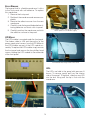
1
Service Manual
Specifications......................................................2
Operation.............................................................3
Installation...........................................................4
Theory of Operation............................................5
Wiring Diagram....................................................6
Troubleshooting...................................................7
Door and Vend Delays......................................10
Repair................................................................11
Parts List............................................................16
801330
02/2007
Easy120 Specifications
Footprint — 32”H x 20”W x 20”D
Panel Depth — 5”
Weight — 270 lbs (approx., empty); 320 lbs (approx. ship)
Boltwork — 5 Point
Hinge — Continuous, heavy duty full length
Manual Drop — Drawer, 4.5” x 1.5”
Inner Compartment — Key locked
Tube Capacity — 120 Tubes (10 columns, 12 tubes/column); Internally loaded
Vend Mechanism — Solenoid activated release for hand operated knob cycle vending
Vend Delay — 2 Minutes default (adjustable by DIP switch 0 to 15 minutes)
Alt Vend — 30 Second Vend Delay (MGR key must be ON)
Door Delay — 10 Minute default (adjustable by DIP switch 0 to 15 minutes)
Armor Car Support — Key override of door delay for instant access
Keys — MGR, VEND, ACO (Armored Car), and Inner Compartment
easy120 Operation
Loading Tubes
Opening the Outer Door
• Open the outer door.
• Put rolled coin or bills into empty tubes.
• Insert full tubes into appropriate columns.
Stickers on the interior of the vend assembly
indicate the number of tubes in each column.
Tubes may be loaded with either end facing
forward.
• Insert the MGR key and turn to ON.
• Press the DOOR button.
• The DELAY/READY indicator will turn red (this
indicates a delay is in progress).
• The MGR key may be removed during the delay
cycle if desired.
• At the end of delay cycle both indicators turn
green.
• Insert the MGR key and turn to ON.
• Press the DOOR button.
• The DOOR indicator will turn off.
• IMMEDIATELY turn the handle and open the
door.
• The door will automatically lock when you close
the outer door.
Vending Tubes
• Insert the VEND key and turn to ON.
• Press the number button corresponding to the
column you want to vend from.
• Rotate the release knob for the selected column.
• Collect your tube from the dispensing tray.
• The vend delay cycle must finish before you
may vend again (the default delay is 2 minutes
unless using the ALT VEND feature).
Armored Car Access
• Insert and turn the ACO key.
• While holding the ACO key, IMMEDIATELY turn
the handle and open the door.
• The door will automatically lock when you close
the outer door.
Alt-Vend feature
•
•
•
•
•
Note: This proceedure is used to enable a 30
second vend delay.
Insert the MGR key and turn to ON.
Press the ALT VEND button.
The vend delay switches to 30 seconds.
Press the ALT VEND button again to switch
back to the normal vend delay.
Switch the MGR key to OFF to disable the 30
second delay feature.
Opening the inner door
• Open the outer door by normal or Armored Car
proceedure.
• Insert the inner door key into the inner door
lock and turn.
• The inner door pulls down to allow access to
the inner compartment.
Manual Drops
• Pull out the manual drop drawer.
• Insert drop envelope into drawer.
• Push manual drop in fully. The drop envelope
will fall into a secure inner compartment.
easy120 installation
Site Preparation
2. Plug the power supply cable into the power
supply jack at the rear of the safe.
3. Plug the standard grounded power plug into a
standard 115VAC outlet.
4. Wait for the display to stabilize (about 10 seconds).
5. Using the OPENING OUTER DOOR procedure
(see Operating Instruction section), unlock the
outer door.
6. Using the VENDING TUBES procedure (see
Operating Instruction section), operate one
column’s vend knob as if a tube were present.
7. These steps verify operation of critical Easy120
features. If the door or vending system cannot
be operated, contact McGunn Technical Support
immediately prior to bolting the safe down (1-800452-4655).
Before installing, make sure there is adequate
clearance for the body and base of the safe as
well as proper electrical power.
Space Requirements
Space must be provided for mounting the safe,
plus required clearance for access. A minimum
gap of one inch must be provided on both sides
and four inches at the rear of the safe. Clearance
must be provided so that the safe door is allowed
to swing open at least 90°.
•1 Inch Side Clearance
• 4 Inches Rear Clearance
• 90° Door Swing Clearance
• Body Height Clearance
Power Requirements
A standard NEMA 15A 115VAC grounded outlet
must be provided within 6 feet of the hinge side of
the safe. The unit may share its AC circuit with other point of sale electronic equipment, but must not
be on the same circuit as rotating machinery such
as a cooler or other refrigeration equipment.
• Standard 115VAC Grounded Outlet
• No Rotating or Heavy Loads on AC Circuit
• Outlet Within Six Feet of Hinge Side
Safe Installation
1. Obtain the anchor wedge kit from inside the
safe and set aside.
2. Obtain the footprint template (shipped inside
the safe).
3. Using a pencil, mark the mounting hole locations on the floor.
4. Drill four 1/2 inch holes to a depth of 3 inches.
The holes must be clean. Use a vacuum to
clean the holes. Do not use water to clean the
holes.
5. Position the safe so that the bolt-holes align
with the holes drilled in the floor. While doing
so, feed the power supply cable and alarm
cable through cabinet openings (if applicable)
for routing access.
6. Drive each anchor wedge in until 1/4 inch to
1 inch of the top protrude through the floor of
the safe.
8. Slide the washers down over each anchor
wedge.
9. Put the nuts on each anchor wedge by hand
until finger tight. Turn approximately three to
four full turns by wrench to complete the tightening.
Installation Procedure
Before proceeding, make sure the space and
power requirements listed above are met for the
mounting location. The safe is shipped with the
outer door locked in the open position with rubber
bumpers preventing accidental door closure.
Remove the Safe From the Pallet
1. Remove wrapping material from the safe.
2. Remove the contents of the safe.
3. Unbolt the safe from the pallet.
Verify Safe Operation
1. Locate the power supply unit packaged inside
the unit. Unwrap the power supply.
Easy120 theory of operation
READY/WAIT LED
MGR KeySwitch
There is a Bi-Color (Red or Green) LED that serves
as the READY or WAIT LED. Any time the system
is in a delay, this LED will turn RED. When there is
no delay in progress this LED will be GREEN. This
LED also serves as a feedback for button presses. Since there is no buzzer on the system, each time
a key is pressed this LED will blink an ORANGE
color whether or not the LED was GREEN or RED
before the button was pressed.
This switch is a key controller switch that activates
all Manager functions. Manager functions include
enabling the ALT VEND function and opening the
outer door. When the key switch is ON you may
activate the ALT VEND function by simply pressing
the ALT VEND button. You may also open the door
by pressing the DOOR button while this key is ON.
This key does not enable normal vending.
Vend KeySwitch
Vend Buttons 1-10
This switch is a key controlled switch that activates
the vending feature. When this key is in the ON
position, a user can vend tubes from the safe. Each
time a tube is vended a delay must be satisfied
before another tube may be vended. When this
key is in the OFF position, no vending can take
place on this system.
If the VEND Key is in the ON position, when a
VEND button is pressed then (1) tube may be
vended from the associated column. After the tube
is vended, the system will then go into delay. The
duration of the delay depends on a DIP switch
setting (factory default is two minutes).
Door Button
ACO KeySwitch
If the MGR key is in the ON position, when the door
button is pressed the system will start the door
delay (if a delay is set on the dip switch). After the
delay has ended, when the door button is pressed
within a 10 minute period while the MGR key is
ON, the door will open.
This switch is a key controlled momentary switch
that allows an armored car carrier (or any other
user that has this key) to immediately open the
door by bypassing the door delay. When this key
is activated, the door will immediately unlock, the
DOOR LED will turn on, and you turn the handle
to open the safe. There is a 30 second interval
between periods this key can be used. So, if you
turn the key and do not open the door, you have
to wait 30 seconds to turn the key again.
Alt Vend Button
If the MGR key is in the ON position, when this
button is pressed the system will either have its
normal vend delay or a 30 second vend delay
(depending on which state it was in before the
press, it alternates states). While the system is in
the ALT VEND state, no matter what the dip switch
delay is set to, the vend delay will immediately go
to 30 seconds. It will continue in this state until
either power is removed, or the ALT VEND mode
is turned off.
DOOR LED
The DOOR LED on the display panel illuminates
when either the ACO key has been activated or the
door time delay has been reached and the door
is ready to be opened. If a manager presses the
DOOR button of the safe while the MGR key is in
the ON position, the door delay will begin. Once
this delay has been reached the DOOR LED will
illuminate and the manager will have 10 minutes
to come back to the safe and press the DOOR
button to open the door. Once the door has been
opened, or the 10 minutes period has expired, the
DOOR LED will then turn off.
Accounting
There is no accounting on the system. It does not
track door or vending events. The system will, however, only allow one tube to vend per request.
Easy120 wiring diagram
LCD DISPLAY MODULE
VEND
DOOR PANEL
KEYPAD MEMBRANE
READY/DELAY LED
DOOR LED
MGR
ACO
J23
J27 J22
JP7
HEARTBEAT
J5
J25
JP8
1 2 3 4 5 6 7 8
S2
J26
10 9 8 7 6 5 4
3 2 1LOCK
VEND SOLENOIDS
J21
LOCK
VEND DROP SENSOR
TRANSMITTER
VEND DROP
SENSOR
RECEIVER
ARMORED CABLE
(TO BACK PANEL)
Easy120 Wiring Diagram
Door LED: Black (top) and white wires to JP8.
Vend Solenoids: Blue wire pairs to associated J7
connector.
Lock: Orange and Black (top two wires of RJ45 at
lock) to J7 LOCK1 connector.
Vend Drop Sensor Transmitter: Yellow and Black wire
harness to J21.
Vend Drop Sensor Receiver: Yellow, Black, and Yellow
wire harness to J25.
Armored Cable: Red, Blue, and Black to J26; Red
and Black to LCD module.
Vend Key Switch: Orange wires to J27.
MGR Key Switch: White wires to J27.
ACO Key Switch: Red and black wires to J22.
LCD Module Data: Flat ribbon cable to J23.
Keypad Membrane: Flat ribbon cable to J5.
Ready/Delay LED: Red (top), black, white wires to
JP7.
Easy120 troubleshooting
introduction
Most problems will fall into one of these categories: mechanical/door operation, vending, power,
or electronics. If you can successfully determine
the nature of the problem you can greatly reduce
the number of possible causes.
Power
If the unit has no power, the display will be off, both
LEDs will be off, and there will be no response
from the keypad.
External Power
Power Supply Jack Wiring at Rear Inside of Safe
The unit is powered by an external DC power supply (Part 15000346). Measure the output voltage to
determine power supply operation up to the back
of the safe (only +12 VDC and +5 VDC and common
are used). If the problem is external verify the
outlet has power and replace the power supply
if faulty. If the power supply output is good and
everything is connected properly, the problem is
inside the safe.
1
3
4
2
5
1 = COM
2 = COM
3 = +5 VDC
4 = –12 VDC
5 = +12 VDC
Armored Cable Routing
Power Supply Output
Internal Power
Possible problems include the cable harness, the
LCD display module, or the main board.
Internally power runs on two sets of wires from
the rear of the safe through an armored cable to
the door.
Inside the back of the safe: two black wires carry
power common from Pin 1 of the jack to J26 (main
board) and the LCD module. A blue wire carries
+12 VDC from Pin 3 on the jack to J26 on the main
board. Two red wires carry +5 VDC from Pin 5 of the
jack to the LCD module and main board J26.
Power Wires from Armored Cable
To: J26 at Main Board
To: LCD Module via Molex Connector
Disconnect J26 and the molex connector to the
LCD panel and check for correct voltages at each
plug (blue = +12 VDC and red = +5 VDC relative to
black). If the armored cable is okay, the problem is
either the LCD module or the main board. Plug J26
in and see if the Heartbeat LED on the main board
blinks. If not, the problem is definitely the main
board. If the Heartbeat indicator does blink, the
problem is more likely to be the LCD module.
Vending
Vending problems may include an empty column,
a tube jam, a solenoid problem, a vend drop sensor problem, or an electronics problem.
Blue Wire Pairs from Solenoids to Main Board
Tube Jam or Empty Column
Open the door and visually inspect to make sure
there are tubes in the column and there is no jam.
If the column is jammed clear the jam.
Solenoid or Main Board
While attempting to vend from the problem column, verify the solenoid energizes (pin pulls up)
when the screen indicates it should. If the solenoid does not, check the connection to the main
board. Check the voltage to the solenoid at the
main board connection while attempting to vend
to determine if the problem is the solenoid or the
main board.
Vend Drop Sensor
If the safe vends properly but the tube count does
not decrement or if the solenoid remains energized even after you physically vend a tube there
is a problem with the vend drop sensor. Check
the physical mounting of the vend drop sensor
transmitter and receiver boards and check for
any obstructions of the beam across the tray area.
Check electrical connections at sensor boards
(transmitter on hinge side, receiver on open side)
and main board J21 and J25. Check continuity
of sensor cables. Replace both boards only if no
other problem is found.
Vend Drop Sensor (Receiver Side Shown)
Keypad Membrane
MGR Key Switch (far right)
VEND Key Switch (to the left)
Vend Key Switch
If the vend key switch or its wires fail, the keypad
will not respond to any attempts to vend even
though the display will work and the door will still
operate.
Keypad
If the keypad membrane is damaged one or more
columns may not respond when you attempt to
vend.
Outer Door
Possible outer door problems preventing operation
may include handle/cam failure, stuck or blocked
bolt work, lock failure, main board failure, key
switch failure, or a wiring problem with a switch
or the lock.
Mechanical
Pressure on the inside of the door from items
stuffed inside can make it very difficult to open the
door. The best solution if this happens is to apply
pressure to the front of the door while turning the
handle. Damaged or jammed bushings can cause
similar symptoms. If the handle cam is loose the
handle will turn without moving the bolt work.
Handle Shaft with Cam (left) and a Guide Bushing (right)
Electrical
Using the normal door procedure attempt to open
the door. If nothing happens when you press the
DOOR button, the problem is the keypad. If both
LEDs turn green at the end of the delay but the
DOOR LED does not go off when you turn the MGR
key, the problem is the MGR keyswitch. If either of
the above are the problem, the ACO key should
still be able to open the door. If the LEDs respond
properly to the MGR keyswitch yet you cannot
open the door using the Normal or Armored Car
Door Procedure the problem is probably either a
lock failure or lock cable.
Main Electronics
The main board is the heart of the Easy120. Component failure on the main board can manifest in
any number of ways ranging from intermittent door
or vending problems to complete display failure,
garbled display, inability to count tubes, or otherwise failure to properly respond. The main board
constantly checks itself as evidenced by a flash
of the Heartbeat LED about once per second. If
the Heartbeat LED does not blink the main board
should be replaced.
Outer Door Lock
Main Board (Heartbeat LED Highlighted)
Easy120 door and vend delays
JP7
J5
Configuring delays
Default Setting
By factory default it is configured with segments
2, 4, and 6 ON and all other segments OFF. This
combination sets a 10 minute DOOR DELAY with
a 2 minute VEND DELAY.
On the main circuit board you will find an eight
segment DIP switch marked S2. This DIP switch
is used to adjust the DOOR DELAY and VEND
DELAY values.
T
J25
JP8
Custom Setting
1 2 3 4 5 6 7 8
Delays are in units of minutes. With power off
change the DIP switches to obtain the desired
delay values. Turn power on and the electronics
will recognize the new delay settings.
S2
J26
S2 DIP Switch Sets Door and Vend Delays
4
DIP Switch Segments
1
2
3
4
OFF OFF OFF OFF
ON OFF OFF OFF
OFF ON OFF OFF
ON ON OFF OFF
OFF OFF ON OFF
ON OFF ON OFF
OFF ON ON OFF
ON ON ON OFF
OFF OFF OFF ON
ON OFF OFF ON
OFF ON OFF ON
ON ON OFF ON
OFF OFF ON ON
ON OFF ON ON
OFF ON ON ON
ON ON ON ON
DOOR DELAY
None
1 Minute
2 Minutes
3 Minutes
4 Minutes
5 Minutes
6 Minutes
7 Minutes
8 Minutes
9 Minutes
10 Minutes
11 Minutes
12 Minutes
13 Minutes
14 Minutes
15 Minutes
3 2 1LOCK
J21
S2 Segments 1 to 4 Set Door Delay
DIP Switch Segments
5
6
7
8
OFF OFF OFF OFF
ON OFF OFF OFF
OFF ON OFF OFF
ON ON OFF OFF
OFF OFF ON OFF
ON OFF ON OFF
OFF ON ON OFF
ON ON ON OFF
OFF OFF OFF ON
ON OFF OFF ON
OFF ON OFF ON
ON ON OFF ON
OFF OFF ON ON
ON OFF ON ON
OFF ON ON ON
ON ON ON ON
VEND DELAY
30 Seconds
1 Minute
2 Minutes
3 Minutes
4 Minutes
5 Minutes
6 Minutes
7 Minutes
8 Minutes
9 Minutes
10 Minutes
11 Minutes
12 Minutes
13 Minutes
14 Minutes
15 Minutes
S2 Segments 5 to 8 Set Vend Delay
LOCK
10
VEND DROP
Easy120 Repair
Warnings
Vend Assembly
The Vend Assembly must be removed in order to
access most of the electrical and electronic components on the inside of the door.
•ONLY FACTORY AUTHORIZED SAFE TECHNICIANS SHOULD ATTEMPT TO SERVICE THE
EASY120 SAFE.
•PROCEDURES AND TOOLS REQUIRED TO DRILL
OPEN THE SAFE ARE NOT IN THIS DOCUMENT.
AUTHORIZED TECHNICIANS WILL BE PROVIDED
WITH THE INFORMATION REQUIRED DIRECTLY
FROM THE FACTORY.
•UNAUTHORIZED SERVICE WILL VOID THE
WARRANTY AND MAY RESULT IN ADDITIONAL
DAMAGE.
•REMOVE POWER BY UNPLUGGING THE EXTERNAL POWER SUPPLY BEFORE CONNECTING OR
DISCONNECTING ANY ELECTRICAL COMPONENTS INSIDE THE SAFE.
•USE ANTI-STATIC PROTECTION AT ALL TIMES
WHEN HANDLING ELECTRONIC CIRCUIT
BOARDS AND COMPONENTS.
To Remove the Vend Assembly:
1. Pull off all ten of the vend knobs from the
front.
Tools
Vend Knobs Slide Off and On
Most repairs to the Easy120 safe require only
common tools. The T-25 Security Torx bit is only
required for accessing the front panel. Be sure to
use a grounding strap any time you are handling
any circuit boards. Standard service tools for the
Easy120 should include the following:
Phillips Screwdriver
3/8” Nut Driver / Wrench
7/16” Nut Driver / Wrench
1/2” Nut Driver / Wrench
T-25 Torx Security Bit
Pliers
Multi-Meter
Grounding Anti-Static Strap
2. Remove the Vend Drop Sensor Boards.
To remove the boards use a phillips screw
driver and remove the two mounting screws
from each board.
Replacement Parts
Always obtain all replacement parts from the factory. Using non-factory parts will void the warranty
and may damage your safe.
Disconnect Drop Sensor Boards (ex. shown left)
or Remove Drop Sensor Boards (ex. shown right)
11
Under the vend assembly
3. Using a 7/16” hex nut driver or wrench remove the six nuts (two on the right, four on
the left) holding the metal Vend Assembly
to the door. Gently slide the entire assembly
back and set it out of the way.
The vend assembly must be removed in order to
access and replace the main circuit board and all
other electronics in this section.
1/2” Nut
T-25 Torx
7/16” Nuts
LCD
Molex
7/16” Capture Nuts:
4 Hinge Side (shown left) and 2 Open Side (shown right)
Casting Repair
To repair any part of the casting assembly remove
all tubes and turn the vend assembly upside down.
Back off the set screw for the casting to service.
Slide out the casting spindle. Pull the front of the
casting free, then the front and rear casting bushing will come loose. Replace damaged parts and
reverse process to reinstall.
3/8” Nuts
Vend Assembly Must Be Removed to Access Most
Electronic Components Including Outer Door Panel Items
Main Board
Use a grounding strap to avoid static damage any
time you handle the main circuit board. Remove
power by unplugging the external power supply
before replacing the main circuit board. When
replacing the main board be sure to carefully
note where each plug to goes so you put them in
the correct jacks with the correct orientation on
the new board. Be sure to set the DIP switch (S2)
correctly and make sure jumper JP1 is installed
L to R: Rear Bushing, Casting, Front Bushing, Spindle
To Reinstall the Vend Assembly:
Reverse the above steps. Be sure the notches in
all of the vend casting spindles are facing up. Be
careful to avoid pinching any wires when mounting the assembly.
Casting Spindle Notches
Facing Up
Avoid Pinched Wires
(ACO Key Switch Wire)
New Main Board
12
and jumper JP9 is installed between its two lower
pins on the replacement board. You may need to
transfer the jumpers from the old board to the new
board. Six phillips screws hold the main circuit
board to the door.
Lock
The lock is mounted on a layer of hard plate with
phillips head screws. It connects to the door via
a short cable (orange and black wires only). The
cable has an RJ45 connector at the lock and a
snap-on plug for the LOCK1 jack at main board.
Solenoids
Each solenoid is held to
the bracket by its nut.
To replace a solenoid
remove first remove the
bracket and cover assembly. Care must be
taken to avoid twisting
and thus damaging the solenoid wires while removing solenoid nuts. Solenoid wires must be
routed through the bracket cover openings close
to the door. The bracket cover prevents anything
from weighing down the solenoid pins. Care must
also be taken to ensure each solenoid cable is
connected to the corresponding column connector
on the J7 jack set.
Lock Connected to Main Board
Solenoids Connect to J7 Jacks (bracket cover not shown)
Vend Drop Sensor Boards
The Receiver module is the one on the open side.
It has a three-pin jack and is electrically connected
to J25 on the main board. The Transmitter module
is mounted on the hinge side. It has a two-pin jack
and is electrically connected to J21 on the main
board.
ACO Key Switch from Interior (left) and Exterior (right)
ACO Key Switch
To Remove the Front Panel:
1. Disconnect the following main board items:
J27 (to key switches), J23 (to LCD module),
J5 (to keypad membrane), JP7 (to READY/
WAIT LED), JP8 (to DOOR LED).
2. Disconnect the power supply molex to the
LCD module.
3. Remove the T-25 Torx Security Head screws
holding the front panel to the door. Be careful to avoid damaging wires routed through
the door.
The ACO Key Switch is mounted directly to the
door, above the front panel and across from the
handle. It is electrically connected to J22 on the
main board.
Front Panel
The front panel must be removed to access and
replace the VEND and MGR key switches, the
DOOR LED, the READY/WAIT LED, LCD module,
or keypad membrane.
13
Keypad Membrane
The keypad itself is a flexible membrane. It sticks
to the front panel with self-adhesive. To replace
this membrane:
1. Remove the front panel.
2. Peel back the membrane and remove completely.
3. Remove the adhesive cover from the new
membrane.
4. Carefully route the keypad ribbon before allowing adhesive surface to stick to panel.
5. Carefully position the membrane and stick
the adhesive surface to the panel.
LCD Ribbon Cable Connection to J23 (left)
Power Input to LCD Module (right)
LCD Module
The LCD module is mounted under the front panel.
The ribbon cable to J23 and the portion of the
power supply wire harness from the LCD Molex to
the LCD module are part of the LCD module assembly. To replace the LCD module simply remove
the front panel and remove the four phillips head
screws holding the LCD module to the underside
of the front panel.
LCD Module Mounting Inside Front Panel
LEDs
Front Panel Exterior View
The LEDs are held to the panel with pressure fit
lenses. To remove, gently pull from the interior
side of the panel. To replace, slide the new LED
into the lens fitting until the tip is flush with the
membrane.
Keypad Ribbon Cable Connection to J5
READY/WAIT (left) and DOOR (right) LEDs
14
Inner Compartment Lock
VEND and DOOR Key Switches
The VEND and DOOR key switches are slotted to
ensure proper orientation and they are held on with
hex nuts. The J27 wire harness includes a pair of
orange wires and a pair of white wires. Each wire
is terminated with spade connectors. Connect the
orange wires to the MGR keyswitch (closest to the
side wall). Connect the white wires to the VEND
key switch.
The lock to the inner compartment is a simple
1/4 turn key lock. The inner compartment door is
attached by a simple hinge and swings down for
access to manual drops.
Inner Compartment Key Lock
Manual Drop Drawer
Keypad Ribbon Cable Connection to J5
The manual drop drawer includes an anti-phish
baffle and steel back stop. The drawer can be
replaced by removing the dual nuts holding the
back stop piece to the rear of the drawer.
Bolt Work
The T-Handle spindle is fitted through a stand-off
on the face of the door. On the inside the cam is
anchored by a 9/16” locknut. When the handle
turns the cam drives the
solid piece bolt work up on
its guides. 1/2” capture nuts
hold the bushings in place
which in turn hold the bolt
work piece flush against the
door. All moving parts are
greased to ensure smooth
Assembled Bolt Guide
operation.
Manual Drop Drawer Back Stop
Top C: Handle Spindle with Cam & Locknut
Bottom L to R: Guide Flatwasher, Nylon Washer, Bushing
15
easy120 Parts list
ELECTRONICS
DOOR HARDWARE
15200100Easy120 Main Board
15000346External Power Supply
15200153Armored Power Harness
15200157Spring-loaded Keyswitch: ACO
15200151Single Key Switch Cable (J22)
800316 Keyswitch (2): VEND & MGR
15200150Dual Key Switch Cable (J27)
801061 Keypad Touch Membrane
15200154LCD with Harness
15008102LED, Ready/Wait Bicolor Red/Green
15000389LED Cable, Ready/Wait (JP7)
15008004LED, Door Green
15000390LED Cable, Door (JP8)
15000391LED Lens (2)
15016000Outer Door Lock
15200152Lock Cable
15200200Drop Transmitter Board
15200251Drop Transmitter Cable (J21)
15200201Drop Receiver Board
15200250Drop Receiver Cable (J25)
801150 Solenoid, w/ nut and wires (10)
3914T-Handle
701327 Handle Spacer
701328 Handle Cam
G-3223 Locknut, Handle 9/16” Hex, 3/8-16
600828 Bolt, One-Piece
701323 Bolt Guide Bushing (3)
801096 Bolt Nylon Washer (3)
801097 Bolt Flat Washer (3)
G-3154 Bolt Locknut 1/2” Hex, 5/16-32 (3)
701362 Hinge Assembly
G-3222 Locknut, Hinge 7/16” Hex, ¼-20 (8)
600827 Drop Tray
701319 Drop Tray Support Bracket
G-3222 Locknut, Brkt/Body 7/16” Hex, ¼-20 (2)
801093 Locknut, Brkt/Tray 10-32 (2)
G-3222 Locknut, Vend Assby 7/16” Hex, ¼-20 (4)
801092 Screw, Main Board, 8-32 5/16 Pan Ph (6)
600876 Outer Panel
06030008Screw, Display Module 4-40 1/4 (4)
CONSUMABLES & STICKERS
801085
801154
801155
801159
801158
800332
800331
801156
801157
VENDING HARDWARE
701326
701428
801189
800303
600883
801057
801160
801062
801063
801058
801084
Solenoid Mounting Bracket
Solenoid Cover
Solenoid Lock Washer (10)
Drop Module Screw 7/16 6-32 (4)
Vend Assembly Chassis
Vend Casting (10)
Vend Casting Set Screw (10)
Vend Casting Rear Bushing (10)
Vend Casting Front Bushing (10)
Vend Casting Spindle (10)
Vend Knob (10)
INTERIOR HARDWARE
600884
701315
801109
600823
GN-4014
GN-1028
G-3223
800215
701334
801094
Inner Door
Inner Door Hinge Assembly
Key Lock, Inner Door
Manual Drop Drawer (w/ back stop parts)
Drawer Back Stop
Bolt, Drawer Back Stop
Locknut, Back Stop 9/16” Hex, 3/8-16 (2)
Cable Clamp 5/16 (4)
Rear Connector Plate
Connector Plate Screws (4)
16
Tube (each)
Column Stickers (for vend assby)
Vend Knob Stickers
Column Currency Decal Stickers
Label, Vend Key
Label, ACO Key
Label, MGR Key
Warning Label, Store Window
Warning Label, Safe