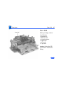
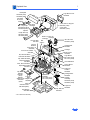
1
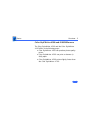
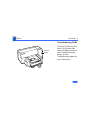
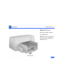
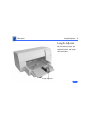
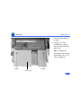
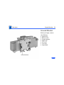
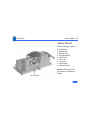
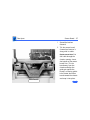
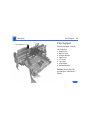
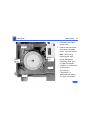
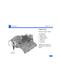
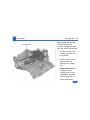
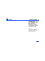
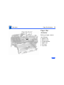
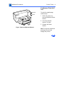
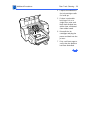
K Service Source
Color StyleWriter
4100 and 4500
K Service Source
Basics
Color StyleWriter 4000 Series
Basics
Overview - 1
Overview
The Color StyleWriter 4000
Series printers are desktop
color bubble-jet printers
for personal use.
Basics
Overview - 2
Color StyleWriter 4500 and 4100 Differences
The Color StyleWriter 4500 and the Color StyleWriter
4100 differ in the following ways:
• Color StyleWriter 4500 can produce photo-quality
prints.
• Color StyleWriter 4500 can print on banner (zfold) paper.
• Color StyleWriter 4500 prints slightly faster than
the Color StyleWriter 4100.
Basics
Overview - 3
Ink Cartridge Configurations
The Color StyleWriter 4500 and 4100 can be configured
with
• Color ink cartridge
• High-performance black ink cartridge
The Color StyleWriter 4500 can also be configured with
• Color ink cartridge
• PhotoGrade ink cartridge.
In the Color StyleWriter 4500, replace the black cartridge
with the PhotoGrade ink cartridge for photo-quality
printing.
Basics
Overview - 4
Troubleshooting LEDs
Resume
Power
The Color StyleWriter 4500
and 4100 have two LEDs,
Power and Resume, that can
aid in troubleshooting the
printer. See the
Troubleshooting chapter for
more information.
Basics
Overview - 5
Ink-jet Technology
Overview
Thermal ink-jet technology involves applying heat to a tiny
measure of ink until it expands and forms a bubble. As the
bubble continues to expand and burst, it is propelled
through one of the nozzles on the ink cartridge. This process
is repeated up to 8,000 times per second.
Each ink cartridge on the Color StyleWriter 4500 and 4100
has 48 nozzles. On the black ink cartridge, all 48 nozzles
are used for black ink. On the color and PhotoGrade
cartridges each color (cyan, magenta, and yellow) has 16
nozzles each.
Basics
Overview - 6
Photo Printing Technology
The Color StyleWriter 4500 uses multiple dye-load
technology to produce photorealistic print-outs. Two ink
cartridges are used to produce these results: the color and
the photo ink cartridges. The color cartridge contains cyan,
magenta, and yellow inks. The PhotoGrade cartridge contains
cyan, magenta, and yellow inks mixed with a black pigment.
The three additional colors in the PhotoGrade cartridge
quadruples the number of ink color ratios that can be
printed in a given area. The resulting colors produced from
the PhotoGrade cartridge are more subtle shades and hues.
The PhotoGrade cartridge also produces smaller ink
droplets, which can be layered on top of each other to vary
the intensity.
Basics
Ink Cartridge Identification - 7
Ink Cartridge
Identification
Caution: Do not get the
printer’s ink on your hands
or clothes. Although the ink
is water soluble, it contains
dyes that will stain.
Color Cartridge
Black Cartridge
Note: The Color
StyleWriter 4500 includes
three ink cartridges: black,
color, and PhotoGrade.
The Color StyleWriter 4100
includes only the black and
color cartridges.
Basics
Ink Cartridge Identification - 8
High-Performance, Black-Only Ink Cartridge
The black ink cartridge contains black ink only.
Color Ink Cartridge
The color ink cartridge contains cyan, magenta, and yellow
inks.
Color PhotoGrade Ink Cartridge
The PhotoGrade ink cartridge contains cyan, magenta, yellow
inks and black pigment.
Important: The Color StyleWriter 4500 includes the ink
cartridge and PhotoGrade paper. For photorealistic results,
the kit contents must be used together. These parts cannot be
used in the Color StyleWriter 4100.
Basics
Ink Cartridge Identification - 9
Identifying
Replacement Ink
Cartridges
6105
The ink cartridges used
with the Color StyleWriter
4100 and 4500 have a
generic cartridge labels.
There is no Apple logo or
Apple part number on the
cartridge. To identify a
cartridge, refer to the
small numeric part number
on the label. This number
can be cross-referenced to
the appropriate Apple
Marketing number in the
chart that follows.
Basics
Ink Cartridge Identification - 10
Identify ink cartridges by cross referencing the chart below.
Apple Marketing
Part Number
M5694G/A
M5693G/A
M5692G/A
Product Description
HP Cartridge
Color Ink Cartridge (CSW
4100 & 4500)
6107
Color PhotoGrade Ink
Cartidge (4500 only)
6104
Black Ink Cartridge (CSW
4100 & 4500)
6106
Note: Apple ink cartridges can be found at most Apple authorized dealers, as well as
most office product and computer superstores. Catalog and mail order houses which
specialize in Macintosh products, such as MacWarehouse, MacMall, and MacZone carry
a complete selection of genuine Apple Printer Supplies. You can also call the Apple
Reseller Referral number at 1-800-538-9696, which will refer you to an
authorized Apple dealer in your area.
Basics
Recommended Paper - 11
Recommended
Paper
Apple recommends Apple
Color Ink-Jet PREMIUM
PLUS Coated Paper. It is the
coated paper of choice to use
with the Color StyleWriter
4100 and 4500 ink-jet
printer.
• Letter size p/n M4792G/
A
• A4-size p/n M4791G/A.
Basics
Printing a Photograph - 12
Printing a Photograph
The Color StyleWriter 4500 has the capability to produce
photo-quality printouts. Follow these procedures
1
2
Remove the black print cartridge and replace it with the
PhotoGrade Ink cartridge.
Load the PhotoGrade paper into the sheet feeder so the
whiter side faces you.
Basics
Printing a Photograph - 13
3
4
5
6
Choose Page Setup from
the File menu.
In the Page Setup dialog
box, select PhotoGrade
from the Paper Type
pop-up menu.
Select the “Use Color
PhotoGrade Ink
Cartridge” option.
Click Print.
Basics
Printing a Banner - 14
Printing a Banner
Follow these steps to print
on banner (z-fold) paper
using the Color StyleWriter
4500.
1
2
Choose Page Setup from
the File menu.
In the Page Setup dialog
box, choose either
Banner US Letter or
Banner A4 from the
Paper Size pop-up
menu.
Basics
Printing a Banner - 15
3
4
5
Banner
Support
6
Banner Lever
Slide the banner lever
to the right until it
clicks into place.
Remove all paper from
the input tray.
Flip up the banner
support in the output
tray.
Put the paper in the
input tray, with a torn
edge at the top of the
stack, facing lengthwise
into the printer.
Basics
Printing a Banner - 16
7
8
Slide the paper width and
length adjusters so they
touch the edges of the
stack of paper.
Click Print.
Note: When printing
stops, press the Resume
button as many times as
necessary to advance the
remaining banner paper
out of the printer.
Basics
Special Servicing Considerations - 17
Special Servicing Considerations
Banner Calibration
After replacing the logic board or ink cartridges you must
re-calibrate the Color StyleWriter 4500 banner printing.
Performing this calibration requires using the Color
StyleWriter 4500 Banner Calibration utility found in the
Diagnostic folder on the Companion CD. Refer to Additional
Procedures for more information.
Capping Assembly Replacement
If a Color StyleWriter 4100 or 4500 printer is brought in
for service, and the customer has had the printer for
awhile, replace the capping unit.
Capping Assembly 4100: 922-3010
Capping Assembly 4500: 922-2855
Basics
- 18
Mechanical Assembly Screws
Important: Do not touch/remove mechancial assembly
screws (for any reason) that are not called out in the Take
Apart chapter for the Color StyleWriter 4000 Series.
Doing so will put the printer out of alignment and will
require installing a new mechanical assembly.
K Service Source
Specifications
Color StyleWriter 4000 Series
Specifications
Characteristics - 1
Characteristics
Print Methods
Throughput
Serial bubble jet ink-on-demand
Best:
Up to one page per minute with the black ink cartridge
Up to .3 page per minute for color
Normal:
Up to three pages per minute with the black ink cartridge
Up to .8 page per minute for color
Draft:
Up to five pages per minute with the black ink cartridge
Up to 1.7 pages per minute for color
Actual speed depends on the documents printed and the Macintosh
used.
Specifications
Characteristics - 2
Note: The Color StyleWriter 4100 prints at slightly slower
rates: up to four pages per minute with the black ink cartridge,
and up to 1.4 pages per minute for color.
Interfaces
• High-speed serial RS-422 port supports serial connection
• Printer can be hooked up to LocalTalk, but not as a shared
printer.
Specifications
Graphics - 3
Graphics
Resolution
Black:
Best: 600 x 600 dpi
Normal: 600 x 300 dpi
Draft: 300 x 300 dpi
Color & Black:
All Modes (plain paper): 300 x 300 dpi
All Modes (other media paper): 600 x 300 dpi
Color & Photo:
Best & Normal (photograde paper): 600 x 300 dpi
Note: The Color StyleWriter 4100 cannot print using the
photo ink cartridge.
Specifications
Print Media - 4
Print Media
Cut Sheets
Labels
Plain paper, coated (recommended for color picture output)
Color PhotoGrade paper (required for photorealistic color output)
LTR, LGL, Executive, A4, A5, B5
U.S. Letter (LTR): 8.5 x 11 in. (215.9 mm x 279.4 mm)
U.S. Legal (LGL): 8.5 x 14 in. (215.9 mm x 355.6 mm)
U.S. Executive: 7.25 x 10.5 in. (184.1 x 266.7 mm)
A4: 8.3 x 11.7 in. (210 mm x 297 mm)
A5: 5.8 x 8.3 in. (148.5 x 210 mm)
B5: 7.2 x 10.1 in. (182 x 257 mm)
Weight: 16-36 lb. Capacity: 100 sheets
Avery paper labels designed for inkjet printers
Letter, A4
Capacity: 25 sheets.
Specifications
Banner
Print Media - 5
U.S. Letter Banner: 8.5 x 11 in. (216 x 279 mm)
U.S. A4 Banner: 8.5 x 14 in. (216 x 356 mm)
Weight: 20 lbs. Capacity: 20 sheets
Note: The Color StyleWriter 4100 cannot print on banner
paper.
Cards
Transparencies
U.S. 4 x 6: 4 x 6 in. (101.6 x 152.4 mm)
U.S. 5 x 8: 5 x 8 in. (127 x 203.3 mm)
A6: 4.1 x 6 in. (105 x 148.5 mm)
Height: 3.9 x 5.8 in. (100 x 148 mm)
Weight: 29-53 lbs. Capacity: 30 cards
Coated transparencies, most inkjet transparencies
Capacity: 50 sheets
Specifications
Envelopes
Print Media - 6
#10: 9.5 x 4.12 in. (241.3 x 104.4 mm)
DL: 4.33 x 8.66 in. (110 x 220 mm)
C6: 4.49 x 6.38 in. (114 x 162 mm)
A2: 4.375 x 5.75 in. (111 x 146 mm)
Weight: 20-24 lbs. Capacity: 20 envelopes
Specifications
Printable Area - 7
Printable Area
Paper, Labels, &
Transparencies
U.S. Letter: 8.5 x 11 in. (215.9 mm x 279.4 mm)
U.S. Legal: 8.5 x 14 in. (215.9 mm x 355.6 mm)
U.S. Executive: 7.25 x 10.5 in. (184.1 x 266.7 mm)
A4: 8.3 x 11.7 in. (210 mm x 297 mm)
Top margin:.26 in. (6.6 mm)
Bottom margin:.59 in. (14.9 mm)
Left & right margins: .25 in. (6.4 mm)
A5: 5.8 x 8.3 in. (148.5 x 210 mm)
Top margin: 26 in. (6.6 mm)
Bottom margin: .84 in. (21.3 mm)
Left & right margins: .25 in. (6.4 mm)
B5: 7.2 x 10.1 in. (182 x 257 mm)
Top margin: 26 in. (6.6 mm)
Bottom margin: .59 in. (14.9 mm)
Left & right margins: .25 in. (6.4 mm)
Specifications
Envelopes
Cards
Printable Area - 8
#10: 9.5 x 4.12 in. (241.3 x 104.4 mm)
DL: 4.33 x 8.66 in. (110 x 220 mm)
C6: 4.49 x 6.38 in. (114 x 162 mm)
A2: 4.375 x 5.75 in. (111 x 146 mm)
Top margin: .84 in. (26 mm)
Bottom margin: .29 in. (6.6 mm)
Left & right margins: 0.125 in. (3.2 mm)
U.S. 4 x 6: 4 x 6 in. (101.6 x 152.4 mm)
U.S. 5 x 8: 5 x 8 in. (127 x 203.3 mm)
A6: 4.13 x 6 in. (105 x 148.5 mm)
Height: 3.9 x 5.8 in. (100 x 148 mm)
Top margin: 0.26 in. (6.6 mm)
Bottom margin: 21.3 in. (.84 mm)
Left & right margins: 0.25 in. (6.4 mm)
Specifications
Ink Cartridges - 9
Ink Cartridges
Type
Ink Color
Shelf Life
Black ink cartridge with integrated ink tank and print head
Three-color ink cartridge with three ink tanks (cyan, magenta,
yellow) and integrated print head
Color PhotoGrade ink cartridge with three ink tanks and integrated
print head
Black
Color (Cyan, magenta, yellow)
PhotoGrade (Cyan, magenta and yellow dyes, and Black pigment)
6 months (installed in printer)
18 months (in original package)
Specifications
Print Cartridge Life
Typical Usable Ink
Number of Nozzles
Ink Cartridges - 10
Black ink cartridge
650 pages at 5% coverage
Color ink cartridge
350 pages at 15% coverage
PhotoGrade ink cartridge
250 pages at 15% coverage
Black ink cartridge
40 ml
Color & PhotoGrade ink cartridges
7.6 ml per tank
Black ink cartridge
48 nozzles
Color and PhotoGrade ink cartridges
48 nozzles (16 per color)
Specifications
Environmental - 11
Environmental
Acoustic Noise Level
Best: 48 dB
Normal: 50 dB
Draft: 52 dB
Temperature
Operating: 41–104°F (5-40°C)
Storage: -40-140°F (-40-60°C)
Humidity
10–80% (noncondensing)
Specifications
Electrical - 12
Electrical
Electrical
Requirements
Power Consumption
AC power adapter
U.S./Japan: 102-132 VAC, 60 Hz ± 3%
UK/Australia: 204-264 VAC, 50 Hz
Europe: 196-253 VAC, 50 Hz
Powered Off (plugged in): 2 W
Powered On (non-printing): 4.5 W
Powered On (printing): 12 W
Specifications
Physical - 13
Physical
Dimensions
Weight
Height: 7.9 in. (199 mm)
Width: 17.2 in. (436 mm)
Depth: 16 in. (405 mm)
11.6 lb (5.3 kg)
K Service Source
Take Apart
Color StyleWriter 4000 Series
Take Apart
Output Tray - 1
Output Tray
Output Tray
Output Tray
1
Slide the output tray out
and remove it from the
printer.
Take Apart
Access Door
Access Door - 2
Access Door
No preliminary steps are
required before you begin
this procedure.
Note: Removing the access
door is not required, but it
may allow you to remove the
top cover more easily.
Take Apart
Access Door - 3
1
Hinge
Hinge
Access Door
Pull the access door off
of the two hinges on the
top cover.
Take Apart
Banner Lever - 4
Banner Lever
Before you begin, remove
the output tray.
Note: The Color StyleWriter
4100 does not include the
Banner Lever.
Banner Lever
Take Apart
Banner Lever - 5
1
2
Hole
3
4
5
Banner Lever
Rest the printer on its
side with the bottom
facing you.
Move the banner level to
the right.
Insert a small flatblade
screwdriver into the
access hole of the
printer’s base.
Push and release the
latch.
Pull the banner lever off
of the base.
Take Apart
Length Adjuster - 6
Length Adjuster
No preliminary steps are
required before you begin
this procedure.
Length Adjuster
Take Apart
Length Adjuster - 7
Opening #2
Opening #1
1
2
3
Latch
4
Length Adjuster
Latch
Rest the printer on its
side.
Pull the length adjuster
straight out until it
stops.
Press and release latch
at opening #1 with a
flatblade screwdriver.
while holding latch, pull
the length adjuster out
until is catches at
second opening.
Repeat step at opening
#2. Pull length
adjuster from top cover.
Take Apart
Input Tray - 8
Input Tray
Before you begin, remove
the output tray.
Take Apart
Input Tray - 9
1
2
Set the printer down on
its base.
Using a T-20 Torx
screwdriver, remove
the two screws from the
Input Tray.
Note: To remove all
remaining screws inside
the printer, use a T-10
Torx screwdriver.
Screw
Input Tray
Screw
Take Apart
I/O Cover - 10
I/O Cover
No preliminary steps are
required before you begin
this procedure.
I/O Cover
Take Apart
I/O Cover - 11
1
2
Hole
3
4
Hole
I/O Cover
Rest the printer on its
side.
Locate the two holes (A
and B) on the base near
the I/O cover.
Insert a jeweler’s
screwdriver into the
holes, and push the
latches straight in until
they unsnap from the
base.
Rotate the I/O cover
away from the base along
its hinges and lift it
from the top cover.
Take Apart
Top Cover
Top Cover - 12
Top Cover
Before you begin, remove
the following:
• Output tray
• Banner lever
• Length adjuster
• Input tray
• I/O cover
Note: Keypad and keypad
cable are part of the top
cover.
Take Apart
Top Cover - 13
Connector
1
Logic Board
Top Cover
Keypad
2
Rest the printer upright
on a flat surface.
Disconnect the keypad
cable from the
connector on the logic
board.
Note: To prevent damage to
the keypad cable, you must
disconnect it before
removing the top cover.
Take Apart
Top Cover - 14
3
4
Latch
Latch
Latch
Latch
Locate the five latches on
the base of the printer:
three on the right and
two on the left.
Starting with the latch
nearest the input tray,
use a small flatblade
screwdriver to
disconnect the latches.
Push the latches
towards the outside of
the printer, and at the
same time, pull the
cover away from the
bottom of the printer.
Note: It may be easier to
unlatch the right side
first.
Take Apart
Top Cover - 15
Top Cover
5
After all five latches are
released, lift off the top
cover.
Caution: Be careful when
lifting off the top cover.
The edges along the base
may be sharp.
Important: Do not remove
or loosen any screws
that are not described in
the following
procedures. Doing so
may affect print quality
and require replacement
of the entire mechanical
assembly.
Take Apart
Pressure Plate - 16
Pressure Plate
Before you begin, remove
the following:
• Output tray
• Banner lever
• Length adjuster
• Input tray
• I/O cover
• Top cover
Pressure Plate
Take Apart
Pressure Plate - 17
Pressure Plate
1
2
Pressure Plate Latch
3
Press the pressure
plate latch outward.
Lift up the left side of the
pressure plate.
Remove the pressure
plate.
Take Apart
Base - 18
Base
Before you begin, remove
the following:
• Output tray
• Banner lever
• Length adjuster
• Input tray
• I/O cover
• Top cover
Base
Take Apart
Base - 19
Paper Motor
Note: The printer is not
attached to the base by any
screws or retainer clips
1
2
Lift the printer from the
base.
Remove the ESD clip
from the base.
Replacement Note: The
ESD clip must touch the
bottom of the paper
motor to ensure proper
grounding.
Base
ESD Clip
Take Apart
Logic Board - 20
Logic Board
Before you begin, remove
the following:
• Output tray
• Banner lever
• Length adjuster
• Input tray
• I/O cover
• Top cover
Caution: Review the ESD
precautions in Bulletins/
Safety.
Logic Board
Take Apart
Logic Board - 21
Note: The logic board contains NVRAM, which contains the
information used to determine the position of the banner
lever. Replacing the logic board, mechanical assembly,
drive gear, or paper feed motor requires re-calibration of
the printer.
See “Banner Calibration” in Additional Procedures for more
information.
Note: The Color StyleWriter 4100 does not provide
banner printing. No calibration is required for that
printer.
Take Apart
Logic Board - 22
1
Ribbon cables
Screw
Screw
2
Disconnect the ribbon
cables by loosening each
end of the black plastic
tab securing the ribbon
cables to the logic board.
Disconnect the
remaining four cables:
• J9: Carriage Motor
• J10: Service Station
• J11: Sensor board
• J12: Paper motor
±
Screw
Screw
J9
J10
J11
J12
Warning: Connector
J9 should be removed
carefully to prevent the
connector from pulling
apart.
Take Apart
Logic Board - 23
3
Ribbon cables
4
Screw
Screw
Screw
Screw
Screw
J9
J10
J11
J12
Using a T-10 Torx
screwdriver, remove
the four mounting
screws.
Remove the logic board
from the printer.
Take Apart
Ground Bracket - 24
Ground Bracket
Before you begin, remove
the following:
• Output tray
• Banner lever
• Length adjuster
• Input tray
• I/O cover
• Top cover
• Logic board
Ground Bracket
Take Apart
Ground Bracket - 25
Screw
Screw
1
2
Remove the two screws
from the ground bracket.
Lift and remove the
bracket from the
printer.
Note: Once the ground
bracket is removed, the
remaining parts comprise
the mechanical assembly.
The base is not included with
the mechanical assembly.
Ground Bracket
Take Apart
Sensor Board - 26
Sensor Board
Before you begin, remove
the following:
• Output tray
• Banner lever
• Length adjuster
• Input tray
• I/O cover
• Top cover
• Logic board
• Ground Bracket
Sensor Board
Caution: Review the ESD
precautions in Bulletins/
Safety.
Take Apart
Sensor Board - 27
1
2
Latch
Latch
Sensor Board
Spread the latches
outward.
Tilt the sensor board
forward and remove it
along with its cable.
Replacement Note: Put
the cable through the
chassis opening. Insert
the bottom of the sensor
board first. Tilt the
board away from the
chassis and align the
guide pin against the
board’s centering guidehole. Rotate the sensor
board toward the chassis
and snap it into place.
Take Apart
Flex Support
Flex Support - 28
Flex Support
Before you begin, remove
the following:
• Output tray
• Banner lever
• Length adjuster
• Input tray
• I/O cover
• Top cover
• Logic board
• Ground Bracket
Caution: Review the ESD
precautions in Bulletins/
Safety.
Take Apart
Flex Support - 29
1
Flex Support
Pull the flex support
straight up and remove
it from the chassis.
Take Apart
Capping Assembly - 30
Capping Assembly
Capping Assembly
Before you begin, remove
the following:
• Output tray
• Banner lever
• Length adjuster
• Input tray
• I/O cover
• Top cover
Caution: Review the ESD
precautions in Bulletins/
Safety.
Take Apart
Capping Assembly
Capping Assembly - 31
Latch
Latch
1
2
Press and release the
two retaining latches.
Remove the capping
assembly from the
printer.
Caution: Do not touch the
rubber caps on the
capping assembly.
Finger oils can damage
the ink cartridge pens.
Note: Rubber cap parts
can crack and wear over
time causing premature
failure of the print
nozzles. Inspect the
capping assembly when
the unit is in for repair.
Take Apart
Purge Unit - 32
Purge Unit
Purge Unit
Before you begin, remove
the following:
• Output tray
• Banner lever
• Length adjuster
• Input tray
• I/O cover
• Top cover
• Capping assembly
Caution: Review the ESD
precautions in Bulletins/
Safety.
Take Apart
Purge Unit - 33
Note: You can remove the
purge unit without first
removing the encoder strip
and carriage belt only if you
use a long screwdriver.
Screw
1
2
3
Screw
Cable
Purge Unit
Disconnect the cable
attached to the motor.
Remove the two screws.
Lift the purge unit up
and out to remove it
from the printer.
Take Apart
Carriage Motor - 34
Carriage Motor
Before you begin, remove
the following:
• Output tray
• Banner lever
• Length adjuster
• Input tray
• I/O cover
• Top cover
• Capping assembly
• Purge Unit
Carriage Motor
Caution: Review the ESD
precautions in Bulletins/
Safety.
Take Apart
Carriage Motor - 35
Screws
2
Carriage Belt
Cable
Idler Hub
1
3
Carriage Motor
Relax tension on the
carriage belt by pushing
in on the idler hub.
Lift the carriage belt off
the carriage motor
pulley.
Disconnect the carriage
motor cable from the
logic board.
±Warning:
Connector
J9 should be removed
carefully to prevent the
connector from pulling
apart.
4
Remove the two screws
at the top of the carriage
motor.
Take Apart
Idler Hub - 36
Idler Hub
Idler Hub
Before you begin, remove
the following:
• Output tray
• Banner lever
• Length adjuster
• Input tray
• I/O cover
• Top cover
Caution: Review the ESD
precautions in Bulletins/
Safety.
Take Apart
Idler Hub - 37
1
Carriage Belt
2
Idler Hub
Idler Hub
Carriage Belt
Carriage Belt
3
Relax tension on the
carriage belt by pushing
in on the idler hub.
Lift the carriage belt off
the carriage motor
pulley.
Slide the idler hub out of
the tension bracket.
Take Apart
Tension Bracket - 38
Tension Bracket
Before you begin, remove
the following:
• Output tray
• Banner lever
• Length adjuster
• Input tray
• I/O cover
• Top cover
• Idler hub
Tension Bracket
Caution: Review the ESD
precautions in Bulletins/
Safety.
Take Apart
Tension Bracket - 39
1
Tension Bracket
2
3
Squeeze the tension
bracket together.
Once the spring tension
is relaxed, swing the
tension bracket and
spring clear of the
chassis.
Lift the tension bracket
and spring off the
chassis.
Take Apart
Paper Motor - 40
Paper Motor
Before you begin, remove
the following:
• Output tray
• Banner lever
• Length adjuster
• Input tray
• I/O cover
• Top cover
Caution: Review the ESD
precautions in Bulletins/
Safety.
Paper Motor
Note: The “Paper Motor”
topic includes the paper
motor and the cluster gear.
Take Apart
Paper Motor - 41
1
Screw
2
Drive
Gear
Paper
Motor
Screw
Cable
Disconnect the paper
motor cable.
Remove the two screws
and remove the paper
motor from the printer.
Note: (4500 only)
Replacing the logic
board, mechanical
assembly, drive gear,
or paper feed motor
requires re-calibration
of the printer.
See “Banner
Calibration” in
Additional Procedures
for more information.
Take Apart
Paper Motor - 42
3
Drive Gear
Remove the drive gear.
Take Apart
Rear Rail
Rear Rail - 43
Rear Rail
Before you begin, remove
the following:
• Output tray
• Banner lever
• Length adjuster
• Input tray
• I/O cover
• Top cover
Caution: Review the ESD
precautions in Bulletins/
Safety.
Take Apart
Rear Rail - 44
1
Screw
Rear Rail
Screw
2
Remove the two screws
attaching the real rail to
the chassis.
Remove the rear rail
from the chassis.
Replacement Note: The
access door sensor lever
must be installed before
replacing the rear rail.
Take Apart
Front Cover Actuator - 45
Front Cover Actuator
Front Cover
Actuator
Before you begin, remove
the following:
• Output tray
• Banner lever
• Length adjuster
• Input tray
• I/O cover
• Top cover
• Rear rail
Caution: Review the ESD
precautions in Bulletins/
Safety.
Take Apart
Front Cover Actuator - 46
1
Front Cover Actuator
Rotate the front cover
actuator forward and
pull it off.
Replacement Note: You
must put the front cover
actuator on before attaching
the rear rail. The actuator
must be in the up position
when attaching the rear rail.
Take Apart
Encoder Strip
Encoder Strip - 47
Encoder Strip
Before you begin, remove
the following:
• Output tray
• Banner lever
• Length adjuster
• Input tray
• I/O cover
• Top cover
Caution: Review the ESD
precautions in Bulletins/
Safety.
Take Apart
Encoder Strip - 48
1
Encoder
Spring
2
3
Encoder
Strip
Push in the encoder
spring to relax the
tension on the encoder
strip.
Disengage the strip
from the right carriage
rod bracket.
Slide the free end of this
strip through the
carriage and disconnect
it from the encoder
spring.
Replacement Note: The
encoder strip is
unidirectional, so there
is no specific back or
front orientation.
Take Apart
Shaft Clip - 49
Shaft Clip
Before you begin, remove
the following:
• Output tray
• Banner lever
• Length adjuster
• Input tray
• I/O cover
• Top cover
Caution: Review the ESD
precautions in Bulletins/
Safety.
Shaft Clip
Take Apart
Shaft Clip - 50
1
Flex the shaft clip away
from the chassis.
Replacement Note: The
shaft clip must be positioned
correctly to avoid paper
jams and to ensure proper
grounding. Position the clip
so the clip’s tab will fit into
the rod’s circular groove.
Apply downward force on the
clip until the clip latches
into place. On the base, make
sure the clip is inside and
touching the base.
Take Apart
Carriage Rod - 51
Carriage Rod
Shaft Clip
Before you begin, remove
the following:
• Output tray
• Banner lever
• Length adjuster
• Input tray
• I/O cover
• Top cover
• Rear rail
• Idler hub
• Tension bracket
• Encoder strip
• Shaft clip
Take Apart
Carriage Rod
Carriage Rod
Carriage Rod - 52
Note: Handle the carriage
rod and carriage unit
carefully. Damage to either
part can affect print quality.
1
2
Lift the left end of the
carriage rod from the
left bracket.
Pull the rod out of the
right bracket and
through the carriage
unit.
Replacement Note: The
carriage rod and
carriage unit are not
replaceable. You may
remove them only to
access other parts.
Take Apart
Carriage Belt
Carriage Belt - 53
Carriage Belt
Before you begin, remove
the following:
• Output tray
• Banner lever
• Length adjuster
• Input tray
• I/O cover
• Top cover
• Rear rail
• Idler hub
• Tension bracket
• Encoder strip
• Shaft retainer clip
• Carriage rod
Take Apart
Carriage Belt
Carriage Belt - 54
Carriage Unit
Caution: Review the ESD
precautions in Bulletins/
Safety.
Note: Handle the carriage
unit carefully. Damage to it
can affect print quality.
1
2
Turn the carriage unit
upside down and grasp
the belt.
Form a loop with the belt
and lift it free from the
carriage.
Replacement Note: The
carriage unit is not
replaceable. You may
remove it only to access
other parts.
Take Apart
Mechanical Assembly - 55
Mechanical
Assembly
Before you begin, remove
the following:
• Output Tray
• Banner lever
• Length adjuster
• Input Tray
• I/O cover
• Top cover
• Logic board
• Ground bracket
• Base
Take Apart
Mechanical Assembly - 56
Note: The base is not
included with the mechanical
assembly.
1
2
Remove the ESD clip
from the base.
Lift the mechanical
assembly from the base.
The mechanical
assembly is not attached
to the base by any
screws or retainer clip.
Important: See Replacement
Note on next page.
Base
ESD Clip
Take Apart
Mechanical Assembly - 57
Replacement Note: (4500
only) Replacing the logic
board, mechanical
assembly, drive gear, or
paper feed motor requires
re-calibration of the
printer.
See “Banner Calibration” in
Additional Procedures for
more information.
Take Apart
Paper Out Actuator - 58
Paper Out
Actuator
Before you begin, remove
the following:
• Output Tray
• Banner lever
• Length adjuster
• Input Tray
• I/O cover
• Top cover
Take Apart
Paper Out Actuator - 59
1
2
3
With a jeweler’s
screwdriver, very
gently pry the plastic
arm up and over the
metal tab on the chassis.
Note: The plastic is
extremely fragile.
With the arm disengaged,
slide the paper out
actuator to the right.
Free the actuator from
underneath the carriage
rod to remove it from
the printer.
K Service Source
Troubleshooting
Color StyleWriter 4000 Series
Troubleshooting
General - 1
General
The Symptom Charts included in this chapter will help you
diagnose specific symptoms related to your product. Because cures
are listed on the charts in the order of most likely solution, try
the first cure first. Verify whether or not the product continues to
exhibit the symptom. If the symptom persists, try the next cure.
(Note: If you have replaced a module, reinstall the original module
before you proceed to the next cure.)
If you are not sure what the problem is, or if the Symptom Charts
do not resolve the problem, refer to the Flowchart for the product
family.
For additional assistance, contact Apple Technical Support.
Troubleshooting
Error Messages and LEDs - 2
Error Messages and LEDs
The Color StyleWriter 4500 and Color StyleWriter 4100 have
two LEDs that can aid in troubleshooting the printer: Resume LED
and Power LED. To interpret these LEDs, refer to Symptom
Charts/LEDs later in this chapter.
Resume
Power
Troubleshooting
Error Messages and LEDs - 3
The printer software also gives error messages to pinpoint
errors.
Make sure the printer is hooked up to a Macintosh and that the
Color StyleWriter 4100/4500 printer driver software is
installed.
Troubleshooting
Diagnostic Tests and Sample Pages - 4
Diagnostic Tests and Sample Pages
The following table summarizes the diagnostic tests and sample
pages that you can run using the Power and Resume buttons.
Perform the tests with printer power on and plain paper in the
paper tray; press and hold down the Power button while pressing
the Resume button. For more information, refer to Additional
Procedures.
Diagnostic Test/Printout
Power Button
Resume Button
Sample Page
HOLD DOWN
Press once (hold briefly)
Continuous Sample Page
HOLD DOWN
Press 10 times
Diagnostic Self Test
HOLD DOWN
Press 5 times
Extended Diagnostic Test
HOLD DOWN
Press 12 times
Clean Print Heads/Ink Cartridges
HOLD DOWN
Press 7 times
Troubleshooting
Symptom Charts/Operation - 5
Symptom Charts
Operation
No power
1
2
3
4
Check power cable connections and recycle power to printer.
Replace power adapter and retest.
Reseat logic board connectors. Replace logic board.
Replace main cover with control panel board.
Does not print
1
2
3
4
5
6
Refer to LEDs later in this chapter.
Turn on printer and restart computer.
Check interface cable and connector. Replace interface cable.
Open Chooser and verify correct printer driver and port.
Replace printer driver.
Reseat logic board connectors. Replace logic board.
Troubleshooting
Symptom Charts/Operation - 6
Carriage unit does not
move to center when
front cover is open
and printer is on
1
2
Refer to “Fixing Carriage Stalls” in Additional Procedures.
Reseat logic board connectors. Replace logic board.
Carriage collides
with left side
1
Make sure clutch actuator is not interfering with carriage
movement. Reposition clutch actuator. See “Fixing Carriage
Stalls” in Additional Procedures for actuator location.
Remove obstructions from carriage and paper paths.
Clean excessive ink or oil from encoder strip, carriage
assembly, and carriage path components.
Replace encoder strip.
Check mechanical assembly for damage and proper operation.
Replace faulty or damaged mechanical assembly.
Reseat logic board connectors. Replace logic board.
2
3
4
5
6
Troubleshooting
Carriage collides
with right side
Symptom Charts/Operation - 7
1
5
6
7
Make sure purge unit and capping assembly do not interfere
with carriage movement.
Manually slide carriage. Remove obstructions from carriage
and paper paths.
Replace any part interfering with carriage movement.
Check mechanical assembly for damage and proper operation.
Replace faulty or damaged mechanical assembly.
Reseat logic board connectors. Replace logic board.
Check carriage motor cable connection.
Replace carriage motor.
1
2
3
Check interface cable and connector.
Replace interface cable.
Reseat logic board connectors. Replace logic board.
2
3
4
I/O failure
Troubleshooting
Ink cartridge won’t
lock in carriage
Symptom Charts/Operation - 8
1
2
3
4
Verify correct ink cartridge. Refer to Basics.
Replace ink cartridge.
Remove and reinstall capping assembly. If faulty replace
capping assembly.
Replace mechanism.
Short pen life
1
2
3
Replace ink cartridge.
Replace capping assembly.
Check purge unit connection. If connected, replace purge unit.
No print or printer
locks up
1
Recycle power to printer. This may require unplugging from
power outlet.
Replace mechanical assembly.
Reseat logic board connectors. Replace logic board.
Replace main cover with control panel board.
2
3
4
Troubleshooting
Stops printing
Leaky cartridge
Symptom Charts/Operation - 9
1
2
3
4
5
6
7
Make sure clutch actuator is not interfering with carriage
movement. Reposition clutch actuator. See “Fixing Carriage
Stalls” in Additional Procedures for actuator location.
Remove obstructions from carriage and paper paths.
Replace any part interfering with carriage movement.
Reseat logic board connectors and retest.
Replace logic board.
Replace carriage motor.
Replace mechanical assembly.
1
2
3
4
5
Clean ink damaged parts. Replace ink damaged parts.
Replace ink cartridge.
Replace mechanical assembly.
Reseat logic board connectors. Replace logic board.
Replace capping assembly.
Troubleshooting
Erratic or slow
movement
Symptom Charts/Operation - 10
1
2
3
4
5
6
7
8
9
10
11
12
13
Manually slide carriage. Remove obstructions from carriage
and paper paths.
Check mechanical assembly for damage and proper operation.
Replace faulty or damaged mechanical assembly.
Inspect carriage rod. If damaged, replace mechanical
assembly.
Reseat power adapter connectors and retest.
Perform “Fiber Track Cleaning” in Additional Procedures.
Inspect and clean purge unit. Check connection.
If problem persists, replace purge unit.
Reseat logic board connectors. Replace logic board.
Replace damaged carriage belt.
Replace mechanical assembly.
Verify that paper-out actuator contacts sensor board. If not,
replace paper-out actuator.
If actuator contacts sensor board, replace sensor board.
Replace carriage motor.
Troubleshooting
Rejects cartridge
Symptom Charts/Operation - 11
1
2
3
4
5
6
7
Paper feeds
continuously
1
2
3
4
Perform “Print Head Cleaning” in Additional Procedures.
Replace ink cartridge.
Clean flex contacts in carriage assembly and remove/
reinstall flex cable.
Verify that paper-out actuator contacts sensor board. If not,
replace actuator.
If actuator contacts board, replace sensor board.
Replace mechanical assembly.
Reseat logic board connectors. Replace logic board.
Manually slide carriage. Remove obstructions from carriage
and paper paths.
Verify that paper-out actuator contacts sensor board. If not,
replace actuator.
If actuator contacts board, replace sensor board.
Reseat logic board connectors. Replace logic board.
Troubleshooting
Grinding, squeaking
or scraping noise
Symptom Charts/Operation - 12
1
Manually slide carriage. Remove obstructions from carriage
and paper paths.
2 Replace any part interfering with carriage movement.
3 Inspect and replace frayed or cut carriage belt.
4 Inspect carriage rod. If damaged, replace mechanical
assembly.
5 Replace mechanical assembly.
6 Replace paper feed motor.
7 Replace drive gear.
8 Replace pivot spring.
9 Verify that paper-out actuator contacts sensor board. If not,
replace actuator.
10 If actuator contacts sensor board, replace sensor board.
11 Remove pressure plate and check for obstructions.
12 Reseat logic board connectors. Replace logic board.
Troubleshooting
Knocking or clicking
noise
Symptom Charts/Operation - 13
1
2
3
4
5
6
Bidirectional
misalignment
1
2
3
4
5
Manually slide carriage. Remove obstructions from carriage
and paper paths.
Check mechanical assembly for damage and proper operation.
Replace faulty or damaged mechanical assembly.
Inspect and replace frayed or cut carriage belt.
Inspect carriage rod. If damaged, replace mechanical
assembly.
Replace drive gear.
Replace carriage motor.
Make sure encoder strip is properly routed through carriage.
Manually slide carriage. Remove obstructions from carriage
and paper paths.
Replace any part interfering with carriage movement.
Make sure carriage motor screws are properly seated.
Replace carriage motor.
Troubleshooting
Paper bonding
Symptom Charts/Operation - 14
1
3
4
If problem is with PhotoGrade cartridge while printing over
LocalTalk, change to serial connection and print in
foreground.
Make sure paper adjustment levers are not applying too
much pressure to paper.
Make sure Input tray is properly installed.
Replace mechanical assembly.
Burning smell
1
2
3
Visually inspect motors. Replace damaged motor.
Reseat logic board connectors. Replace logic board.
Replace mechanical assembly.
No trouble found
1
2
Run Self Tests. Refer to Additional Procedures.
Perform Diagnostic Tests. Refer to Additional Procedures.
No response when
used with G3
computer
Upgrade to the Color StyleWriter 4500 driver, version 1.1 or
later. Refer to this URL online: http://www.apple.com/support/
2
Troubleshooting
Symptom Charts/Paper - 15
Paper
Paper sticks together
1
2
3
4
5
6
7
8
Fan paper and remove excess sheets from paper tray.
Verify that media meets specifications.
Stack media against right wall of In Tray.
Verify that paper-out actuator contacts sensor board. If not,
replace actuator.
If actuator does contact sensor board, replace board.
Remove pressure plate and check for obstructions.
Replace pressure plate.
Replace mechanical assembly.
Troubleshooting
Paper skews
Symptom Charts/Paper - 16
1
Perform diagnostic test to verify that print skew is out of
specification. Refer to Additional Procedures.
2 Keep stack of media between 1/4 and 3/4 inch high in Input
tray.
3 Verify that media meets specifications.
4 Make sure width adjuster is against media.
5 Make sure Input tray is firmly installed.
6 If margin on left side of page gets larger toward bottom of
paper, cause is likely Input tray. Try replacing width
adjuster.
7 Perform Banner Adjustment. See Additional Procedures.
8 If margin on right side of page gets larger near bottom of
paper, chassis is likely cause. Replace mechanical assembly.
9 Remove pressure plate and check for obstructions.
10 Replace pressure plate.
11 Replace mechanical assembly.
Troubleshooting
Paper jams
Symptom Charts/Paper - 17
1
2
3
4
5
6
7
Paper doesn’t load
completely
1
2
3
4
5
6
7
Remove media from paper path. Refer to Additional
Procedures.
Verify media meets specifications.
Check paper feed motor connection. If connected, replace
paper feed motor.
Remove pressure plate and check for obstructions.
Replace pressure plate.
Inspect pivot assembly for damage or obstructions.
Replace mechanical assembly.
Clean rollers.
Inspect paper-out actuator and verify contacts sensor board.
If damaged or not making contact, replace actuator.
If actuator does contact sensor board, replace board.
Remove pressure plate and check for obstructions.
Replace pressure plate.
Replace mechanical assembly.
Reseat logic board connectors. Replace logic board.
Troubleshooting
Paper doesn’t eject
Symptom Charts/Paper - 18
1
2
3
4
5
6
7
Inspect “wings” to be sure they are properly and completely
installed.
Remove and reinstall Out tray.
Remove media from paper path. Refer to Additional
Procedures.
Verify media meets specifications.
Inspect clutch actuator
Make sure clutch actuator is not interfering with carriage
movement. Reposition clutch actuator. See “Fixing Carriage
Stalls” in Additional Procedures for actuator location.
Replace logic board.
Troubleshooting
Paper feeds
continuously
Symptom Charts/Paper - 19
1
2
3
4
5
6
7
Inspect paper-out actuator and verify contacts sensor board.
If damaged or not making contact, replace actuator.
If actuator does contact sensor board, replace board.
Remove pressure plate and check for obstructions.
Replace pressure plate.
Check paper feed motor connection. If connected, replace
paper feed motor.
Check operation of mechanical assembly. If damaged, replace
mechanical assembly.
Reseat logic board connectors. Replace logic board.
Troubleshooting
Symptom Charts/Print Quality - 20
Print Quality
Missing dots
Carriage moves but
printer doesn’t print
1
2
3
4
5
6
Perform “Fiber Track Cleaning” in Additional Procedures.
Perform “Print Head Cleaning” in Additional Procedures.
Make sure ink cartridges are set firmly.
Use only specified paper, envelopes, transparencies, and
backprint film.
Replace ink cartridge. See Additional Procedures chapter.
Reseat logic board connectors. Replace logic board.
1
2
3
4
5
Be sure tape is removed from ink cartridges.
Perform “Print Head Cleaning” in Additional Procedures.
Replace ink cartridge. See Additional Procedures.
Reseat logic board connectors. Replace logic board.
Replace mechanical assembly.
Troubleshooting
Incomplete print
Symptom Charts/Print Quality - 21
1
2
3
4
5
6
Blurring or fuzzy
printing
1
2
3
4
5
6
7
8
Use only specified paper, envelopes, transparencies, and
backprint film.
Perform “Print Head Cleaning” in Additional Procedures.
Check that carriage clears clutch actuator. See “Fixing
Carriage Stalls” in Additional Procedures.
Replace ink cartridge. See Additional Procedures.
Reseat logic board connectors. Replace logic board.
Replace mechanical assembly.
Use only specified paper, envelopes, transparencies, and
backprint film.
Remove and reseat interface cable.
Perform “Fiber Track Cleaning” in Additional Procedures.
Perform “Print Head Cleaning” in Additional Procedures.
Replace ink cartridge. See Additional Procedures.
Reseat logic board connectors. Replace logic board.
Replace purge unit.
Replace mechanical assembly.
Troubleshooting
Underlines or streaks
Symptom Charts/Print Quality - 22
1
2
3
4
5
6
7
Prints wrong color
1
2
3
4
5
Use only specified paper, envelopes, transparencies, and
backprint film.
Perform “Fiber Track Cleaning” in Additional Procedures.
Perform “Print Head Cleaning” in Additional Procedures.
Replace ink cartridge. See Additional Procedures.
Reseat all connectors.
Replace logic board.
Check operation of mechanical assembly. If damaged, replace
mechanical assembly.
Perform “Print Head Cleaning” in Additional Procedures.
Replace ink cartridge. See Additional Procedures.
Reseat all connections.
Replace logic board.
Replace mechanical assembly.
Troubleshooting
Fails Printer Tests
Symptom Charts/Print Quality - 23
1
2
3
4
5
6
7
Use only specified paper, envelopes, transparencies, and
backprint film.
Perform “Fiber Track Cleaning” in Additional Procedures.
Perform “Print Head Cleaning” in Additional Procedures.
Replace ink cartridge. See Additional Procedures.
Reseat all connectors.
Replace logic board.
Check operation of mechanical assembly. If damaged, replace
mechanical assembly.
Troubleshooting
Symptom Charts/LEDs - 24
LEDs
Power and Resume
lights off
1
2
3
4
5
Check power connections and power source.
Recycle power to printer.
Replace power cord.
Replace power adapter and retest.
Reseat logic board connectors. Replace logic board.
Power and Resume
lights blinking in
unison, printer
won’t print
1
2
3
4
5
6
Verify printer has paper and ink cartridges.
Make sure ink cartridges are properly seated.
Check for carriage stall. Refer to Additional Procedures.
Check for paper jam. Refer to Additional Procedures.
Reseat logic board connectors. Replace logic board.
Check that paper out actuator properly contacts sensor
board. If not, replace actuator.
If paper-out actuator is properly positioned, replace sensor
board.
7
Troubleshooting
Power and Resume
lights flashing
alternately, printer
won’t print
Symptom Charts/LEDs - 25
1
2
3
4
Close top cover.
Check printer connections.
Verify proper printer driver and printer port are selected.
Perform printer self tests. Refer to “Printer Tests” in
Additional Procedures.
5 Send another file.
6 Replace printer cable.
7 Check for carriage stall. Refer to Additional Procedures.
8 Check for paper jam. Refer to Additional Procedures.
9 Reseat logic board connectors. Replace logic board.
10 Replace mechanical assembly.
11 Verify that paper-out actuator contacts sensor board. If not,
replace actuator.
12 If actuator contacts board, replace sensor board.
Troubleshooting
Symptom Charts/LEDs - 26
Power and Resume
lights on steady,
printer won’t print
1
2
3
Try recycling power to printer.
Reseat logic board connectors. Replace logic board.
Replace mechanical assembly.
Power light on but
Resume light
flashing, printer
won’t print
1
Install media. Make sure media is not buckled in IN tray and
paper length and width adjusters are firmly against media
stack.
Check for paper jam. See Additional Procedures.
Install ink cartridge or replace empty ink cartridge. Make
sure ink cartridge snaps into place and cover is closed. Refer
to Additional Procedures.
Reseat ink cartridge.
Press Resume button. Page should print and eject to OUT tray.
2
3
4
5
K Service Source
Additional Procedures
Color StyleWriter 4000 Series
Additional Procedures
Printer Tests - 1
Printer Tests
Resume
Power
Self Test
Follow these steps to print
the self test sample page.
1
Figure: Power and Resume Buttons
2
With the printer on,
press the Resume button
until the printer begins
printing.
Release the Resume
button.
The printer will print one
copy of the self test sample
page (see the following
pages).
Additional Procedures
Printer Tests - 2
The Color StyleWriter 4100
self test sample page is
shown at left.
Additional Procedures
Printer Tests - 3
The Color StyleWriter 4500
self test sample page is
shown at left.
Additional Procedures
Printer Tests - 4
Continuous Print Self
Test
Resume
Power
To print the sample page
continuously:
1
2
3
Figure: Power and Resume Buttons
With the printer on,
press and hold the Power
button.
Press the Resume
button 10 times.
Release the Power
button.
Note: To stop the continuous
printing test you must
unplug the printer.
Additional Procedures
Printer Tests - 5
Diagnostic Test
Resume
Power
To print the diagnostic selftest:
1
2
3
Figure: Power and Resume Buttons
With the printer on,
press and hold the Power
button.
Press the Resume
button 5 times.
Release the Power
button.
The printer will print out
the diagnostic self-test page
shown on the next page.
Additional Procedures
Printer Tests - 6
Print Skew Test upper
Nozzle
Pattern
Print Skew Test lower
Figure: Diagnostic Self-Test Page
Additional Procedures
Printer Tests - 7
Interpreting the Diagnostic Test
All interpretations refer to the Diagnostic Self-Test Page shown on the preceding page.
Nozzle Patterns
The black and colored diagonal test patterns verify that all dots on each cartridge are firing.
If dots are missing, refer to “Symptom Charts/Print Quality” in Troubleshooting.
Print Cartridge Identification
The letters identifies the cartridge type (K=black; C=color).
Model Name
The model name indicates the model of the printer, such as the Color StyleWriter 4500.
Model Number
Model number provides the part number of the printer.
Additional Procedures
Printer Tests - 8
Revision
Revision notes the firmware version installed.
Date
Date contains the date and time that the firmware was installed.
Pen State
Pen State is used after calibrating the printer. Refer to “Calibration” later in this chapter
for interpretation.
Status
Status indicates the printer’s status and any failures.
I/O
I/O identifies I/O serial type RS-422A for Macintosh.
Additional Procedures
Printer Tests - 9
Print Skew Test
A
A
OUT
C
Figure: Print Scew Test Page
C
C
A
IN
The Print Skew test
measures the print margins
to ensure that paper moves
through the printer
properly and printing does
not appear tilted. To test for
print skew:
1
2
Print the Diagnostic
Self-Test page.
Fold the top edge of the
page down towards the
bottom, aligning the left
edge of the paper without
creasing the paper.
Additional Procedures
Printer Tests - 10
3
A
A
OUT
C
C
C
A
IN
Note where the vertical
line left of the A falls in
relation to the two
vertical lines to the left
of the C.
• If the single vertical
line falls between the
two vertical lines, the
print skew is within
product specification.
• If these lines do not
match up, print skew
is out of specification.
See “Print Skew” in
Troubleshooting.
Additional Procedures
Printer Tests - 11
Extended Diagnostic Test
To print the Extended Diagnostic Test page:
1
With the printer on, press and hold the Power button.
3
Release the Power button.
2
Press the Resume button 12 times.
The printer will print out the Extended Diagnostic Test page
shown on the next page.
Additional Procedures
Printer Tests - 12
Nozzle
Pattern
NMV
Figure: Extended Diagnostic Test Page
Additional Procedures
Print Head Cleaning - 13
Print Head Cleaning
Use the following cleaning procedure to correct blurred
characters, horizontal white streaks, and missing dots. No
preliminary steps are required.
Caution: Do not get the printer’s ink on your hands or
clothes. Although the ink is water soluble, it contains dyes
that will stain.
Note: Cleaning the print head sprays quantities of ink. Do
this procedure sparingly if you wish to conserve ink.
Additional Procedures
Print Head Cleaning - 14
Cleaning Procedure
Follow these steps to clean
the print head.
Resume
Power
1
2
3
With the printer on,
press and hold the Power
button.
Press the Resume
button 7 times.
Release the Power
button.
The printer cleans the print
head and prints a test page in
the process.
Additional Procedures
Print Head Cleaning - 15
Alternatively, you may also
clean the print cartridges
as follows:
1
2
Select Page Setup from
any document, or select
File/Print Window
from the Finder, and
click Utilities.
From the Utilities
window, find Clean Print
Cartridges and click
Start.
Additional Procedures
Print Head Cleaning - 16
Verifying the Cleaning Procedure
The cleaning procedure produces a print-out like the one shown on the next page. This
print-out consists of three parts:
• Set of two groups of diagonal lines (black and colored) at the top of the page.
• Bands of black and color in the middle of the page.
• Set two groups of diagonal lines (black and colored) at the bottom of the page.
Nozzle
Pattern
Before
Cleaning
Nozzle
Pattern
After
Cleaning
Figure: Print-out After Cleaning Print Heads
Additional Procedures
Print Head Cleaning - 17
Use this information to verify whether the cleaning
procedure was successful:
1
2
Inspect the two diagonal lines (black and colored) at the
top of the page.
• If you see a gap in a line, one or more dots are clogged
in the ink cartridge that produced the line.
Inspect the bottom group of lines for gaps.
• If the gap present in the top group of lines is not
repeated in the bottom group of lines, the cleaning
routine was successful.
• If the gap remains in the bottom group of lines,
repeat the cleaning routine. If the problem persists
after repeating the cleaning procedure three times,
replace the cartridges.
Additional Procedures
Fiber Track Cleaning - 18
Fiber Track Cleaning
Small fibers can attach themselves to ink residue on the
carriage unit or ink cartridge and drag through the wet ink
on the page, causing fine streaks of ink or print smear.
These streaks are called "fiber tracks."
To clean ink and debris from around the ink cartridge nozzle
plate and the carriage unit, perform the following steps.
1
Remove the ink cartridges. Refer to “Replacing Ink
Cartridges” later in this chapter.
Caution: Do not leave the ink cartridges uncapped for
more than 8 minutes, or the nozzles may clog.
Additional Procedures
Fiber Track Cleaning - 19
2
3
Nozzle
Plate
Inspect the print head of
each ink cartridge for
ink and debris buildup.
If there is noticeable
ink buildup or even a
single fiber, clean each
nozzle with a moistened
foam rubber swab.
Note: Do not wipe across
or toward the nozzle
plate.
Note: Use distilled water
and a clean foam rubber
swab (or a clean, lintfree cloth) to clean the
print head nozzles.
Additional Procedures
Fiber Track Cleaning - 20
4
5
6
7
I nspect the underside of
the ink cartridge cradle
for build-up.
If there is noticeable
build-up of ink or a
single fiber, wipe each
black hook-shaped arm
with a clean, moistened
foam rubber swab.
Reinstall the ink
cartridges and plug the
power cord back into the
printer.
Print a self-test page to
verify that the problem
has been eliminated.
Additional Procedures
Replacing Ink Cartridges - 21
Replacing Ink Cartridges
Note: Replacement ink cartridges do not have an Apple logo
or Apple part number. To identify the correct replacement
cartridge you must cross-reference a small numeric part
number on the label to the Apple marketing number. Refer
to “Identifying Replacement Ink Cartridges” in Basics.
Caution: Each ink cartridge contains a print head that sprays
the ink onto the paper. Treat the print head gently so you
don’t damage its tiny nozzles.
Caution: The carrier holds the ink cartridges and moves
them back and forth when you are printing a document.
Don’t slide the carrier by hand or you will damage the
printer.
1
Turn on the printer, and open the access door. The
carriage moves to the center of the printer.
Additional Procedures
Replacing Ink Cartridges - 22
2
With the carriage in the
center position, unplug
the power cord at the
printer and remove the
ink cartridges.
Additional Procedures
Replacing Ink Cartridges - 23
3
Grasp each cartridge by
its sides and carefully
remove the tape from the
cartridge’s print head.
Make sure you remove
the tape from both
cartridges.
Note: You may safely
touch the colorful caps
or the black plastic, but
be careful not to touch
any other part.
Additional Procedures
Replacing Ink Cartridges - 24
4
Color Ink
Cartridge
Black Ink
Cartridge
Slide the color and black
ink cartridges down into
the carrier, and press
them into place. Press
until you hear a snap and
the cartridge fits snugly
into the carrier.
Note: The ink cartridges
should be difficult to
remove. If a cartridge
feels loose, it is not
seated properly.
Additional Procedures
Replacing Ink Cartridges - 25
5
Resume
Light
Plug in the power cord
and close the printer
cover. You should hear
the carrier move to the
right.
Note: If the resume light
blinks after you close
the cover, the ink
cartridges are not
installed properly. Turn
the printer off and
reseat the ink
cartridges.
Additional Procedures
Aligning the Ink Cartridges - 26
Aligning the Ink Cartridges
Whenever you install a new ink cartridge, follow the steps
below to align the cartridges.
1
2
Make sure there is plain paper in the paper tray and the
printer is on.
Note: If the resume light blinks, the ink cartridges are
not installed properly. Refer to “Replacing Ink
Cartridges” for additional information.
Select Page Setup from the File menu.
Additional Procedures
Aligning the Ink Cartridges - 27
3
4
In the Page Setup dialog
box, click Utilities.
In the Utilities dialog
box, find Align Print
Cartridges and click
Start.
Additional Procedures
Aligning the Ink Cartridges - 28
5
Read the message that
appears, and click Align.
Clicking Align produces a
print-out like the one
shown on the next page.
Additional Procedures
Aligning the Ink Cartridges - 29
Figure: Ink Cartridge Alignment Page
Additional Procedures
Aligning the Ink Cartridges - 30
6
Examine the patterns
that appear on the
print-out. From the
sets of parallel lines,
select the horizontal set
and the verticle set for
which the black and
magenta lines are most
closely aligned.
Note: If you cannot see
black lines, make sure
you have removed the
tape from the black ink
cartridge. If you cannot
see magenta lines, make
sure the tape is removed
from the color cartridge.
Additional Procedures
Aligning the Ink Cartridges - 31
7
I n the dialog window
shown at left, click the
number and letter
corresponding to the best
aligned sets of black and
magenta parallel lines,
and then click OK.
The printer produces
another print-out like
the one shown on the
next page. Use this
print-out to verify that
the alignment is
acceptable.
Additional Procedures
Aligning the Ink Cartridges - 32
Figure: Ink Cartridge Post-Alignment Page
Additional Procedures
Aligning the Ink Cartridges - 33
8
I f the pattern on the
second printed page is
acceptable, click OK in
the dialog window shown
at left. If the pattern is
not acceptable, click
Align to repeat the
alignment procedure.
Additional Procedures
Banner Calibration - 34
Banner Calibration
After replacing the logic board or mechanical assembly you
must re-calibrate the Color StyleWriter 4500 banner
printing. Note: Only the 4500 has banner printing.
Important: Performing this calibration requires using the
Color StyleWriter 4500 Banner Calibration utility found on
the Companion CD (path: Diagnostic Utilities/Color
SW4500 Banner Calibration).
1
2
Copy the Banner Calibration utility to the computer and
make sure the printer is on and connected to the
computer’s printer port.
Set the banner lever to the cut-sheet (left-most)
position. The banner lever must be in the cut-sheet
position or the paper may be misaligned and banner
paper may not be picked.
Additional Procedures
Banner Calibration - 35
3
4
5
Launch the “Color
SW4500 Banner
Calibration” utility.
Select the serial port
that is being used by the
printer, and click Send
File.
Wait until the utility
completes the
calibration routine and
prints the slightly
modified Diagnostic Test,
similar to one shown on
the next page.
Additional Procedures
Figure: Banner Calibration Page
Banner Calibration - 36
Additional Procedures
Banner Calibration - 37
6
Observe the Pen State value on the Diagnostic Test
printout.
The Bump value should fall within the range of 140230.
• If the number is less than 140, verify that the
banner lever is positioned all the way to the left.
• If the number is greater than 230, verify that the
pivot assembly is installed correctly in the printer.
Additional Procedures
Clearing Paper Jams - 38
Clearing Paper Jams
The paper jam error state occurs if the printer detects
paper at the platen after attempting to eject paper to the OUT
tray. The Power and Resume lights alternately blink to
indicate this condition.
Note: The Power and Resume lights alternately blink to
indicate other error conditions, such as a carriage stall.
Make sure this condition is caused by a paper jam.
Caution: Clear paper jams by feeding paper through the
paper path; do NOT pull paper out by force. Doing so could
damage the printer.
Additional Procedures
Clearing Paper Jams - 39
Follow these stpes to clear a
paper jam:
1
Resume
Power
2
With the printer on,
open the access door and
press the Resume button
repeatedly. This causes
the drive rollers to move
the paper forward, one
line at a time.
When you have removed
the paper, close the
access door to print.
Additional Procedures
Fixing Carriage Stalls - 40
Fixing Carriage Stalls
The carriage stalls error state occurs if the printer detects
a problem with the carriage movement. The Power and
Resume lights alternately blink to indicate this condition.
Note: The Power and Resume lights alternately blink to
indicate other error conditions, such as a paper jam. Make
sure this condition is not caused by a paper jam or another
data communications error.
Try these steps to fix a carriage stall:
1
With the printer off, open the access door and inspect the
carriage path for any obstructions that might interfere
with carriage movement. If the carriage is not locked in
the home position, try sliding it across the carriage rod.
Additional Procedures
Fixing Carriage Stalls - 41
2
3
Carriage
4
Belt
Rod
Clutch
Check that the white
plastic clutch actuator is
not interfering with
carriage movement.
Inspect the carriage belt.
If damaged, replace it.
Inspect the carriage
assembly, service
station, and carriage rod.
If any of these
mechanism components
appears damaged,
replace it.
K Service Source
Exploded View
Color StyleWriter 4000 Series
Exploded View
1
Nameplate
922-3008 (4100)
922-2858 (4500)
Logic Board Cover
922-2838
922-2859
AC Power
Adapter
Cover, Main w/ Keypad
922-3004 (4100)
Cover, Main
922-2835 (4500)
Holder Wing
Tray Paper 922-2837
922-3005 (4100)
922-2836 (4500)
Adjuster
Length with Cap
922-3012 (4100)
922-2860 (4500)
Color Ink
Black Ink
Cartridge
Cartridge
Bar
Encoder Strip
922-2841 Adjust *
Ink Tank Case
922-2857 (4500)
Tension
Bracket*
Pivot Spring
922-2842
Front Cover Actuator
922-2844
Pin, Idler 922-2840
Carriage Belt
922-2851
Carriage*
Pad, Friction
922-2849
Logic Board
661-1354 (4100)
661-1431 (4500)
Idler Hub 922-2845
Clip, Shaft 922-2850
Paper Feed Motor
922-2852
Gear, Drive 922-2843
Paper Motor Cable
922-2847
Cap, Width
Adjuster
922-3011
(4100)
Pressure
Adjuster
Plate
Width w/Cap w/Right Wall
922-3003
922-2853
(4500)
Ground Bracket*
Sensor Board
922-2834
Paper Out
Actuator
922-2848
Carriage Motor
922-2846
Mechanical
Assembly
661-1355 (4100)
661-1430 (4500)
Capping
Assembly
922-3009 (4100)
922-2854 (4500)
Paper
Selection Lever
922-2839 (4500)
Feet, Bottom
922-2856
* Part of Mechanical Assembly
Purge Unit
922-2855
Clip, ESD, Kit
922-2833