1
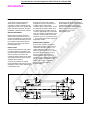
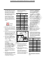
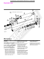
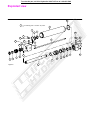
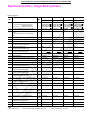
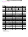
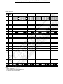
To order this part, call Lifco Hydraulics USA Toll Free at 1-800-952-7849
Vickers®
Service Data
Cylinders
Series TV Hydraulic Cylinders
Installation & Service Manual
5004.02/EN/0496/M
To order this part, call Lifco Hydraulics USA Toll Free at 1-800-952-7849
Contents
Introduction . . . . . . . . . . . . . . . . . . . . . . . . . . . . . . . . . . . . . . . . . . . . . . . . . . . . . . . . . . . . . . . . . . . . . . . . . . . . . . . . . . . . . . . . . 3
Cylinder Installation . . . . . . . . . . . . . . . . . . . . . . . . . . . . . . . . . . . . . . . . . . . . . . . . . . . . . . . . . . . . . . . . . . . . . . . . . . . . . . . . . . 4
Troubleshooting . . . . . . . . . . . . . . . . . . . . . . . . . . . . . . . . . . . . . . . . . . . . . . . . . . . . . . . . . . . . . . . . . . . . . . . . . . . . . . . . . . . . . 5
Service . . . . . . . . . . . . . . . . . . . . . . . . . . . . . . . . . . . . . . . . . . . . . . . . . . . . . . . . . . . . . . . . . . . . . . . . . . . . . . . . . . . . . . . . . . . . 6
Exploded View . . . . . . . . . . . . . . . . . . . . . . . . . . . . . . . . . . . . . . . . . . . . . . . . . . . . . . . . . . . . . . . . . . . . . . . . . . . . . . . . . . . . . . 8
Maintenance . . . . . . . . . . . . . . . . . . . . . . . . . . . . . . . . . . . . . . . . . . . . . . . . . . . . . . . . . . . . . . . . . . . . . . . . . . . . . . . . . . . . . . . . 8
Seal Kits . . . . . . . . . . . . . . . . . . . . . . . . . . . . . . . . . . . . . . . . . . . . . . . . . . . . . . . . . . . . . . . . . . . . . . . . . . . . . . . . . . . . . . . . . . 10
Replacement Parts . . . . . . . . . . . . . . . . . . . . . . . . . . . . . . . . . . . . . . . . . . . . . . . . . . . . . . . . . . . . . . . . . . . . . . . . . . . . . . . . . . 12
How to Order . . . . . . . . . . . . . . . . . . . . . . . . . . . . . . . . . . . . . . . . . . . . . . . . . . . . . . . . . . . . . . . . . . . . . . . . . . . . . . . . . . . . . . 18
Model Code (Cylinder Identification) . . . . . . . . . . . . . . . . . . . . . . . . . . . . . . . . . . . . . . . . . . . . . . . . . . . . . . . . . . . . . . . . . . . . 19
To order this part, call Lifco Hydraulics USA Toll Free at 1-800-952-7849
Introduction
Purpose of manual
Custom cylinders
Replacement parts
This manual has been prepared to
assist users of Vickers Series TV
cylinders for properly maintaining and
repairing their units. In the sections that
follow, instructions are given for proper
installation, maintenance and overhaul.
Although the model code has been
arranged to cover the vast majority of
available options, there will be
occasions when an option which cannot
be coded will be required. When such
an option has been specified, enter an
“X” for the appropriate item in the model
code. For example, an application which
requires a custom thread on the end of
the piston rod, an “X” is inserted for item
7. The cylinder will include a unique five
digit design number.
Each design number has a completed
bill of materials on file in a quick retrieval
computerized storage system. This
gives the Field Sales Representatives
rapid access in identifying and
specifying genuine Vickers
replacements parts.
General information
Model codes have many variations
within a basic model series. They are
covered by variables in the model code.
Service inquiries should always include
the complete model code number as
stamped on the head or cap and the
three digit plant code.
How to order
Vickers has developed an easy system
for ordering Series TV Cylinders. This
system has been developed to improve
ease of ordering. The model code
consists of sixteen alpha-numeric digits
which fully describe the most common
standard options offered.
To specify your Series TV cylinder,
review the Model Code section for a full
description of each option available and
corresponding code.
Replacement cylinders
Every custom cylinder is assigned a
unique design number. This number is
contained in the last five digits of the
sixteen digit model code. Item 12 is
always an alpha character. The “Stroke”
and “Extra Rod Projection” positions
(items 12 through 16) become the
“Design Number” items for custom
cylinders. When ordering a replacement
part or cylinder, give the sixteen digit
model code or the five digit design
number to your local Vickers
Representative.
Figure 1. TV Cylinder Section View
To order this part, call Lifco Hydraulics USA Toll Free at 1-800-952-7849
Cylinder Installation
All Vickers Series TV cylinders are
individually tested and inspected before
shipment to assure freedom from
defects. Plugs are inserted in the ports
to protect threads and keep foreign
matter from entering the cylinder prior to
installation.
Mounting and alignment
Position the cylinder loosely in the
mounting and check the alignment of
the piston rod with the load connection
at both ends of the stroke. If the
cylinder is too large to move by hand,
proceed with piping and installation and
operate cylinder throughout the stroke
prior to connection.
Trunnion and swivel mount bearings
should fit closely for the entire length of
the pin, and must be square with the
load connection throughout the stroke.
Flush or foot mounted cylinders may be
pinned or keyed to prevent shifting
during high shock loads.
Always use the wrench flats when
connecting piston rod to load to prevent
damage to the sealing surface. Tighten
piston rod against shoulder. If cylinder
has been pressurized, relieve all
pressure prior to turning the piston rod.
Piping connections
All piping connections should be
deburred and the system thoroughly
flushed to purge all contaminants prior
to connecting cylinder ports. Care
should be taken to prevent over
tightening of the piping connections.
Cylinder operation
Cycle cylinder a few times with reduced
load and pressure. Hydraulic cylinders
may be erratic due to trapped air, but
will normally purge themselves after
several cycles. Some cylinders may be
equipped with air bleed screws which
can be slowly loosened with a male
metric key wrench, then re-tightened
after air is purged.
Cushioned cylinders are adjusted and
tested prior to shipping, but usually
require additional adjustment after
connection to the work load. The
cushion adjustment screw has a retainer
plate to prevent inadvertent removal of
the screw. A male metric hex wrench is
required to adjust the cushion screw.
To increase effectiveness of the
cushion, turn the adjustment screw
clockwise. To provide less cushion, turn
the screw counterclockwise. Most
orifices are fully open with two full turns
of the screw from the closed position.
The final position of the screw should be
a balance between any shock or bounce
at the start of the cushion and the final
impact of the piston at the end of stroke.
To order this part, call Lifco Hydraulics USA Toll Free at 1-800-952-7849
Troubleshooting
Most problems in fluid power circuits
result in a gradual or sudden loss of
power in the work cylinders, which may
cause them to stall or move slower than
required. This chart assumes that all
other components of the circuit such as
the pump, relief valve, control valves,
hydraulic supply, etc. have been
checked and the problem has been
isolated to the cylinder.
Properly installed and maintained
cylinders should function for millions of
cycles. Premature cylinder failures are
usually caused by system or application
problems that can be prevented. The
purpose of this chart is to aid in identifying
and correcting the most common causes
of premature cylinder malfunction.
Check Cylinder for
Evidence of:
Caused By:
Action Required:
Excessive wear on
piston rod.
Side load due to misalignment between cylinder
and load.
Check alignment of rod with load connection at
all points in stroke.
Pivot mount cylinder without proper stop tubing.
Follow Vickers cylinder catalog design
recommendations.
Exceptionally dirty environment.
Clean and flush the entire system, deburr
connections.
Worn rod wiper.
Shield piston rod area from direct contact with
contaminant.
Lack of, or improperly adjusted cushions.
Reference adjustment instructions in this
manual.
Load and piston speed combination exceeds
cylinder cushion capacity.
Consult your VIckers Sales Engineer.
Lack of, or improperly adjusted speed controls.
Add or adjust flow controls to reduce piston speed.
Excessive system pressure.
Reduce pressure to minimum required to move
the load.
Contamination in
y
cylinder.
Impact damage or
broken parts.
Permanent deformation System pressure in excess of cylinder rating.
g static
or damaged
seals.
l
High pressure developed in cylinder cushion.
Seal damage such as
y,
loss of elasticity,
shape,
h
etc.
t
Table 1.
Follow Vickers cylinder catalog design
recommendations.
Consult your VIckers Sales Engineer.
Cylinder externally loaded while control valve is
closed.
Reduce load magnitude or resize cylinder.
Excessive temperature in environment or
system.
Install replacement sealing system with proper
rating.
Incompatible hydraulic fluid.
Refer to Vickers cylinder catalog for compatible
sealing system.
Cylinder stored in horizontal position for
extended period.
Replace seals, store vertically with rod up.
To order this part, call Lifco Hydraulics USA Toll Free at 1-800-952-7849
Service
The following instructions illustrate the
complete rebuilding of your Vickers
Series TV hydraulic cylinder.
Refer to Figure 4 exploded view.
4. Remove the elastomer wiper from
the outer most groove by carefully
prying it out of the groove with the
dull brass tool.
5. The non-metallic wear band can be
removed from the cartridge in a
similar fashion.
CAUTION
Before breaking a circuit connection,
make certain that power is OFF and
system pressure has been released.
Lower all vertical cylinders, discharge
accumulators, and block any load
whose movement could generate
pressure. Plug all removed units and
cap all lines to prevent the entry of dirt
into the system.
6. Lightly lubricate the new rod seal,
o-rings, wear band and wiper. Install
them in the cartridge as shown in
Figure 2. Carefully lead the outside
sealing edge into each groove. Be
careful not to damage the seal or
wiper.
3. Remove the rod seal from the
cartridge by carefully prying it out of
the groove with a dull brass (or other
soft material tool.)
35
70
Table 2.
Complete rebuild
1. Repeat steps 1, 2, 3, 4 and 5 in
Replacing rod seals section.
2. Remove the tie rod nuts, loosening
in a cross sequence pattern.
Carefully remove the cap or head
from the tie rods and inspect for
damage or signs of contamination.
Rod seal
4. The piston does not have to be
removed from the rod for normal
piston seal replacement. The piston
seal can be removed by inserting a
thin tool under the seal and running
it around the circumference of the
piston. The elastomer energizer
under the face seal should also be
removed.
Replacing rod seals
2. The Quick Change rod cartridge
allows rod seal replacement without
disturbing the tie rods. Remove any
burrs from the wrench flat area of the
piston rod. Place the cylinder in a vice,
rod end up if possible. Remove the rod
cartridge by rotating it counterclockwise
with a spanner wrench. (If an
appropriate spanner wrench is not
available, service is best performed by
disassembling the entire cylinder. The
cartridge can then be removed by
placing a bar such as a square
shanked screw driver in the cartridge
slots, after removing the rod from the
head.)
26
52
Wiper
Required tools
1. Once the cylinder is removed from
service, fully retract the piston rod
and remove all port connections.
Drain any hydraulic fluid by manually
cycling the cylinder. Large cylinders
can be carefully cycled with air
pressure.
110
140
3. Remove the cylinder body from the
head/cap. Slide the piston rod
assembly out of the cylinder body. It
is not normally necessary to remove
the tie rods if threaded into a tapped
head or cap for servicing, unless the
tapped head or cap is mechanically
damaged.
Wear band
Spanner wrench
Adjustable wrench
Soft brass tool
Thin tool
Copper padded vice
Rubber mallet
Torque wrench
160
200
5. Remove the nonmetallic wear band
which simply snaps into the groove
on the piston’s outer diameter.
Figure 2.
7. Carefully replace the cartridge on
the rod so that seal or wiper lips are
not damaged when placing them
over the piston rod. Threaded
cartridges should be turned
clockwise and tightened with a
spanner wrench.
8. The bolt cartridges on larger rods of
units produced prior to 1996 use a
retainer plate. Slide the retainer plate
into position. Replace the retainer
screws, and tighten in a cross
sequence pattern. Torque to the
values shown in
Table 2.
Bore
(mm)
125
Rod
(mm)
90
Torque
(ft. lb.) (Nm)
34
45
6. If piston removal is required, clamp
the piston rod securely in a copper
padded vice to protect the rod finish.
To order this part, call Lifco Hydraulics USA Toll Free at 1-800-952-7849
7. Heat the piston to approximately
175_C with a torch or oven to break
the anaerobic adhesive. Insert a
spanner wrench in the drilled holes
on the piston face and break the
seal by rapping the wrench with a
rubber mallet, rotating the piston in a
counterclockwise direction.
On small cylinders, an alternate
method not requiring a spanner
wrench is to clamp the piston in a
soft jawed vice and turn the rod,
using an adjustable wrench on the
rod flats.
CAUTION
THE PISTON IS HOT!
8. Unscrew the piston and set it aside.
9. Remove the cushion collar from the
rod, if the cylinder is cushioned on
the head end. Let the rod cool before
re-assembly.
energizer should be installed in the
bottom of the groove before
installing the plastic face seal, as
shown in Figure 3.
Rod ∅
(mm)
Piston Torque
(ft. lb.)
(Nm)
12
15
20
14
20
27
18
30
40
22
30
40
28
40
54
36
40
54
45
50
67
56
100
135
70
135
180
90
250
340
110
400
540
140
550
740
Table 3.
10. Snugly secure the rod into the vice.
Replace the cushion collar on the
rod (if required). Thoroughly clean
all metallic surfaces with a
non–petroleum based cleaner and a
wire brush, if necessary.
Plastic face seal
Elastomer
energizer
11. Apply anaerobic adhesive near the
rod shoulder (or collar) on the rod
threads and on the piston I.D.
threads.
12. Tighten the piston on the rod to the
torque listed in Table 3, using the
spanner wrench holes provided in
the piston.
13. Install new seals by placing one side
in the piston groove and stretching
the seal around the piston
circumference with the thin tool used
in disassembly. The elastomer
17. Snap the wear band on the piston
into the wide groove. Lubricate the
piston O.D. and seals. Carefully
insert the piston rod assembly into
the cylinder body. The body is
designed to easily accept the piston
with the sealing system in place.
18. Install the body O–ring in the head
body groove. When properly
installed, the O–ring should remain
in the head when inverted. Grease
will hold the o-ring in place if
required. Place the cylinder head
with tie rods on the body.
19. Repeat steps 6, 7 and 8 in
“Replacing rod seals” section.
20. Start the tie rod nuts until snug
against the head or cap and lay the
cylinder on its side. Secure the
cylinder horizontally into a vice or
clamped to a flat surface.
21. Tighten the tie rod nuts gradually in
a cross sequence pattern to equally
distribute forces around the cylinder
with a torque wrench. The required
torque values are listed in Table 4.
Check each nut a second time after
reaching full torque.
Rod ∅
(mm)
NOTE
Be sure to follow the adhesive
manufacturer’s
recommendations regarding
surface preparation, priming
requirements, proper adhesive
for the thread size, and cure time
prior to pressurization. Failure to
do so could result in improper
sealing and retention.
16. Shorter cylinders are more easily
assembled in a vertical position.
Insert the body O–ring in the cap
body groove and position the
cylinder body on the cap.
25
Figure 3.
14. Cylinder body O–rings are easily
removed using a thin blade tool.
Care should be taken to avoid
damaging the surface finish in the
groove with the tool.
15. Metallic cushion sleeves can be
replaced by removing the snap ring
sleeve retainers.
Note the sleeve orientation in the
groove before removal. Some
sleeves are not symmetrical and
new sleeves must be installed in the
groove in the same orientation.
Tie Rod Torque*
(ft. lb.)
(Nm)
4
5,5
32
7
11
40
14
19
50
33
45
63
50
68
80
105
140
100
150
205
125
340
460
160
690
935
200
1120
1520
Table 4.
*Recommended torque values using
MoS2 lubricant with 0.12 coefficient of
friction.
To order this part, call Lifco Hydraulics USA Toll Free at 1-800-952-7849
Exploded view
14
23
???? Retaining plate – ball Chk. Adj. screw
??
9
14
8
7
25
26
22
24
27
18
17
20
18
4
21
20
19
19
28
3
2
6
12
16
28
13
5
Figure 4.
11
15
10
1
Maintenance
Inspection
All parts in the unit must be kept clean
during the overhaul. Handle each part with
care and always work in a clean area.
Periodic inspection of the fluid condition
and tube or piping connections can save
time consuming breakdowns and
unnecessary parts replacement. The
following should be checked regularly:
1. All hydraulic connections must be
kept tight. A loose connection in a
pressure line will permit the fluid to
leak out. If the fluid level becomes
so low as to uncover the inlet pipe
opening in the reservoir, extensive
damage to the pump can result. In
suction or return lines, loose
connections permit air to be drawn
into the system resulting in noisy
and/or erratic operation.
2. Clean fluid is the best insurance for
long service life. Therefore, the
reservoir should be checked
periodically for dirt or other
contaminants. If the fluid becomes
contaminated, the system should be
drained and the reservoir cleaned
before new fluid is added.
3. Filter elements also should be checked
and replaced periodically. A clogged
filter element results in a higher
pressure drop. This can force particles
through the filter which would ordinarily
be trapped, or can cause the by-pass
to open, resulting in a partial or
complete loss of filtration.
4. Air bubbles in the reservoir can ruin
the pump and other components. If
bubbles are seen, locate the source
of the air and seal the leak.
To order this part, call Lifco Hydraulics USA Toll Free at 1-800-952-7849
Cleanliness
Thorough precautions should always be
observed to insure the hydraulic system is
clean:
1. Clean (flush) entire new system to
remove paint, metal chips, welding
shot, etc.
2. Filter each change of oil to prevent
introduction of contaminants into the
system.
3. Provide continuous oil filtration to
remove sludge and products of wear
and corrosion generated during the
life of the system.
4. Provide continuous protection of
system from entry of airborne
contamination by sealing the system
and/or by proper filtration of the air.
5. During usage, proper oil filling and
servicing of filter, breathers, reservoirs,
etc., cannot be over emphasized.
6. Thorough precautions should be taken
by proper system and reservoir
design, to insure that aeration of the
oil will be kept to a minimum.
Vickers supports and recommends the
hydraulic Systems Standards for
Stationary Industrial Machinery
advanced by the American National
Standards Institute; ANSI/(NFPA/JIC)
T2.24.1–1991. Key elements of this
Standard as well as other vital
information on the correct methods for
treating hydraulic fluid are included in
Vickers publication #561; “Vickers Guide
to Systemic Contamination Control,”
available from your local Vickers
distributor or by contacting Vickers.
Recommendations on filtration and the
selection of products to control fluid
condition are included in this publication.
Sound Level
Noise is only indirectly affected by the
fluid selection, but the condition of the
fluid is of paramount importance in
obtaining optimum reduction of system
sound levels.
Some of the major factors affecting the
fluid conditions that cause the loudest
noises in a hydraulic system are:
1. Very high viscosities at start–up
temperature can cause pump noises
due to cavitation.
2. Running with a moderately high
viscosity fluid will slow the release of
air captured in the fluid. The fluid will
not be completely purged of such air
in the time it remains in the reservoir
before recycling through the system.
3. Aerated fluid can be caused by
ingestion of air through the pipe
joints of inlet lines, high velocity
discharge lines, cylinder rod
packings or by fluid discharging
above the fluid level in the reservoir.
Air in the fluid causes a noise similar
to cavitation.
Hydraulic Fluid
Recommendations
Oil in a hydraulic system performs the
dual function of lubrication and
transmission of power. It constitutes a
vital factor in a hydraulic system, and
careful selection of it should be made
with the assistance of a reputable
supplier. Proper selection of oil assures
satisfactory life and operation of system
components with particular emphasis on
hydraulic pumps. Any oil selected for
use with pumps is acceptable for use
with valves, cylinders or motors.
Order literature #694 for oil selection
recommendations.
Adding Fluid to the System
When hydraulic fluid is added to the
system, it should be pumped through a
10 micron absolute filter. The use of a
Vickers Clean Cart portable filtering
transfer unit to filter clean fluid into the
system is recommended. For further
information on the Clean Cart transfer
unit, obtain service drawing #601.
It is important that the fluid be kept clean
and free from any substance that may
cause improper operation or wear to the
cylinder, pump and other hydraulic units.
Therefore, the use of cloth to strain the
fluid should be avoided to prevent lint
from entering the system.
Replacement Parts
Reliable operation throughout the
specified operating range is assured
only if genuine Vickers parts are used.
Sophisticated design processes and
materials are used in the manufacture of
our parts. Substitutes may result in early
failure.
Product Life
The service life of these products is
dependent on environment, duty cycle,
operating parameters and system
cleanliness. Since these parameters
vary from application to application, the
ultimate user must determine and
establish the periodic maintenance
required to maximize life and detect
potential component problems.
Fluids
Proper fluid condition is essential for
long and satisfactory life of hydraulic
components and systems. Hydraulic
fluid must have the correct balance of
cleanliness, materials and additives for
protection against wear of components,
elevated viscosity and inclusion of air.
Essential information on the correct
methods for treating hydraulic fluid is
included in Vickers publication 561;
“Vickers Guide to Systemic
Contamination control,” available from
your local Vickers distributor or by
contacting Vickers, Incorporated.
Recommendation of filtration and the
selection of products to control fluid
condition are included in #561.
Recommended cleanliness levels using
petroleum oil under common conditions
is based on the highest fluid pressure
levels in the system.
Fluids other than petroleum, severe
service cycles or temperature extremes
are cause for adjustment of these
cleanliness codes. See Vickers
Publication #561 for exact details.
System Pressure Level
Product
70
bar
Cylinders 20/18/15
140
bar
210+
bar
20/18/15 20/18/15
To order this part, call Lifco Hydraulics USA Toll Free at 1-800-952-7849
Seal Kits
Rod Cartridge Seals Kits (1)
“N” Normal
“L” Low
Friction
“T” High
Temperature
“N” Normal
“L” Low
Friction
“T” High
Temperature
Seal Kit No.
Seal Kit No.
Seal Kit No.
Seal Kit No.
Seal Kit No.
Seal Kit No.
6533N–TVBB
6533N–TVCE
6533L–TVBB
6533L–TVCE
6543T–TVBB
6543T–TVCE
6633N–TVBB
6633N–TVBB
6633L–TVBB
6633L–TVBB
6643T–TVBB
6643T–TVBB
14
22
6533N–TV2C
6533N–TVDG
6533L–TV2C
6533L–TVDG
6543T–TV2C
6543T–TVDG
6633N–TV2C
6633N–TV2C
6633L–TV2C
6633L–TV2C
6643T–TV2C
6643T–TV2C
18
22
28
6533N–TVCE
6533N–TVDG
6533N–TVEJ
6533L–TVCE
6533L–TVDG
6533L–TVEJ
6543T–TVCE
6543T–TVDG
6543T–TVEJ
6633N–TVCE
6633L–TVCE
6643T–TVCE
22
28
36
6533N–TVDG
6533N–TVEJ
6533N–TVGL
6533L–TVDG
6533L–TVEJ
6533L–TVGL
6543T–TVDG
6543T–TVEJ
6543T–TVGL
6633N–TVDG
6633L–TVDG
6643T–TVDG
28
36
45
6533N–TVEJ
6533N–TVGL
6533N–TVHN
6533L–TVEJ
6533L–TVGL
6533L–TVHN
6543T–TVEJ
6543T–TVGL
6543T–TVHN
6633N–TVEJ
6633L–TVEJ
6643T–TVEJ
36
45
56
6533N–TVGL
6533N–TVHN
6533N–TVKQ
6533L–TVGL
6533L–TVHN
6533L–TVKQ
6543T–TVGL
6543T–TVHN
6543T–TVKQ
6633N–TVGL
6633L–TVGL
6643T–TVGL
45
56
70
6533N–TVHN
6533N–TVKQ
6533N–TVLS
6533L–TVHN
6533L–TVKQ
6533L–TVLS
6543T–TVHN
6543T–TVKQ
6543T–TVLS
6633N–TVHN
6633L–TVHN
6643T–TVHN
56
70
90
6533N–TVKQ
6533N–TVLS
6533N–TVNU
6533L–TVKQ
6533L–TVLS
6533L–TVNU
6543T–TVKQ
6543T–TVLS
6543T–TVNU
6633N–TVKQ
6633L–TVKQ
6643T–TVKQ
70
90
110
6533N–TVLS
6533N–TVNU
6533N–TVLW
6533L–TVLS
6533L–TVNU
6533L–TVLW
6543T–TVLS
6543T–TVNU
6543T–TVLW
6633N–TVLS
6633L–TVLS
6643T–TVLS
90
110
140
6533N–TVNU
6533N–TVLW
6533N–TVNZ
6533L–TVNU
6533L–TVLW
6533L–TVNZ
6543T–TVNU
6543T–TVLW
6543T–TVNZ
6633N–TVNU
6633L–TVNU
6643T–TVNU
Bore
Size
Rod
Diameter
25
12
18
32
40
50
63
80
100
125
160
200
Piston Seal Kits (2)
(1) Rod Cartridge Seal Kits Include:
(2) Piston Seal Kits Include:
1
1
1
2
1
2
1
1
Rod wiper
Rod seal
Rod Wear band
O.D. Bearing seal
Back-up ring (when req’d)
Body O-rings
Piston wear band
Piston seal
To order this part, call Lifco Hydraulics USA Toll Free at 1-800-952-7849
Exploded view
14
23
???? Retaining plate – ball Chk. Adj. screw
??
9
14
7
8
25
26
22
24
27
18
17
20
18
4
21
20
19
19
28
3
2
6
12
13
5
Figure 5.
10
1
11
15
16
28
To order this part, call Lifco Hydraulics USA Toll Free at 1-800-952-7849
Replacement Parts - Single Rod Cylinders
Refer to Figure 5.
Key
No
No.
No
Req’
d
BORE SIZE 25
BORE SIZE 25
BORE SIZE 32
BORE SIZE 32
ROD 12
ROD 18
ROD 14
ROD 22
Piston rod
Non–cushioned
(# = rod end type) Cushioned head end
Cushioned cap end
Specify stroke
Cushioned both ends
1
1
1
1
TV82BVBA10B
TV82BVBF10B
TV82BVBC10B
Tv82BVBL10B
TV82EVBA10B
TV82EVBF10B
TV82EVBC10B
TV82EVBL10B
TV82CV2A10B
TV82CV2F10B
TV82CV2C10B
TV82CV2L10B
TV82GV2A10B
TV82GV2F10B
TV82GV2C10B
TV82GV2L10B
Rod wiper (Normal sealing system option)
1
7946–012
7946–018
7946–014
7946–022
Rod bearing- Place appropriate code into V in
part no.
A = Normal sealing; B = Low friction/high
temp.
1
TV81BV000
TV81EV000
TV81CV000
TV81GV000
*4
Rod seal (Normal sealing system option)
1
7942–012
7942–018
7942–014
7942–022
*5
Rod wear band
1
8126–012
8126–018
8126–014
8126–022
*6
Seal O.D. bearing
2
5145-019-A
5145-023-A
5145-023-A
5145-026-A
7
Cushion sleeve (Head end)
(Rod end cushion cylinders only)
1
N/A
N/A
N/A
N/A
8
Retainer ring (Head end)
(Rod end cushion cylinders only)
1
N/A
N/A
N/A
N/A
9
Body (Consult factory if intermediate
trunnion mount) Specify stroke
1
TV57BA
TV57BA
TV572A
TV572A
**1
*2
3
10
Part Name
Cushion collar
1
TV93BB1C
TV93EB1C
TV93C21C
TV93G21C
*11
Piston wear band
1
7949–025
7949–025
7949–032
7949–032
*12
Piston seal (Normal sealing system option)
1
7948–025
7948–025
7948–032
7948–032
Piston
1
TV53BF0B7
TV53BF0E7
TV532F0C7
TV532F0G7
13
*14
Body O–ring (Normal sealing system option)
2
5145-023-A
5145-023-A
5145-027-A
5145-027-A
15
Retainer ring (Cap end)
(Cap cushioned cylinders only)
1
N/A
N/A
N/A
N/A
16
Cushion sleeve (Cap end)
(Cap cushioned cylinders only)
1
N/A
N/A
N/A
N/A
17
Cushion adjusting screw
(2 req’d if cushioned both ends)
1 or 2
TV95–025
TV95–025A
TV95–025
TV95–025A
18
Cushion adjusting O–ring
(2 req’d if cushioned both ends)
1 or 2
5145-003-A
5145-003-A
5145-003-A
5145-003-A
19
Steel ball (1 req’d if cushioned head end)
1
02–152533
02–152533
02–152533
02–152533
20
***
Ball retainer
(1 req’d if cushioned head end)
1 or 2
TV98-025
TV98–025
TV98–025
TV98–025
*21
Back-up ring
1
N/A
N/A
N/A
N/A
22
***
Air bleeder screw
A/R
TV94–025
TV94–025
TV94–025
TV94–025
23
Retaining plate – Ball check adj. screw
1 per
screw
7971–025
7971–025
7971–025
7971–025
24
Retaining plate – Cushion adj. screw
1 per
screw
7972–025
7972–025
7972–025
7972–025
25
Retaining plate – Air bleed adj. screw
1 per
screw
7973–025
7973–025
7973–025
7973–025
26
Retaining plate drive screws
(Included with retaining plate)
A/R
27
Tie rods (Specify mtg. style/bore & stroke)
4
TV56
TV56
TV56
TV56
28
Tie rod nuts (Specify mtg. style/bore & stroke)
A/R
5305–003
Notes:
* Sold in seal kit only
** A four character suffix will appear at the end.
A
A
5305–003
B
5305–004
*** Order item #18 for O–rings req’d
B
5305–004
To order this part, call Lifco Hydraulics USA Toll Free at 1-800-952-7849
Replacement Parts
Refer to Figure 5.
Key
No
No.
No
Req’d
BORE SIZE 40
BORE SIZE 40
BORE SIZE 40
BORE SIZE 50
BORE SIZE 50
BORE SIZE 50
ROD 18
ROD 22
ROD 28
ROD 22
ROD 28
ROD 36
**1
1
1
1
1
TV82EVCA10B
TV82EVCF10B
TV82EVCC10B
TV82EVCL10B
TV82GVCA10B
TV82GVCF10B
TV82GVCC10B
TZ82GVCL10B
TV82JVCA10B
TV82JVCF10B
TV82JVCC10B
TV82JVCL10B
TV82GVDA10B
TV82GVDF10B
TV82GVDC10B
TV82GVDL10B
TV82JVDA10B
TV82JVDF10B
TV82JVDC10B
TV82JVDL10B
TV82LVDA10B
TV82LVDF10B
TV82LVDC10B
TV82LVDL10B
*2
1
7946–018
7946–022
7946–028
7946–022
7946–028
7946–033
3
1
TV81EV000
TV81GV000
TV81JV000
TV81GV000
TV81JV000
TV81LV000
*4
1
7942–018
7942–022
7942–028
7942–022
7942–028
7942–036
*5
1
8126–018
8126–022
8126–028
8126–022
8126–028
7944–036
*6
2
5145-023-A
5145-026-A
5145-029-A
5145-026-A
5145-029-A
5145-133-A
7
1
SH–92–R–15
N/A
N/A
N/A
N/A
N/A
8
1
5194–118–HD
N/A
N/A
N/A
N/A
N/A
9
1
TV57CA
TV57CA
TV57CA
TV57DA
TV57DA
TV57DA
10
1
TV93EC1C
TV93GC1C
TV93JC1C
TV93GD1C
TV93JD1C
TV93LD1C
*11
1
7949–040
7949–040
7949–040
7949–050
7949–050
7949–050
*12
1
7948–040
7948–040
7948–040
7948–050
7948–050
7948–050
13
1
TV53CF0E7
TV53CF0G7
TV53CF0J7
TV53DF0G7
TV53DF0J7
TV53DF0L7
*14
2
5145-030-A
5145-030-A
5145-030-A
5145-034-A
5145-034-A
5145-034-A
15
1
5194–75–DG
5194–75–DG
5194–75–DG
5194–100–DG-R
5194–100–DG-R
5194–100–DG-R
16
1
SH–92–B–15
SH–92–B–15
SH–92–B–15
TV920135A
SH–92–B–20
SH–92–B–20
17
1 or 2
TV95–040
TV95–040
TV95–040
TV95–040
TV95–040
TV95–040
18
1 or 2
5145-005-A
5145-005-A
5145-005-A
5145-005-A
5145-005-A
5145-005-A
19
1
N/A
02–157952
02–157952
02–157952
02–157952
02–157952
20
***
1
N/A
TV98–040
TV98–040
TV98–040
TV98–040
TV98–040
*21
1
N/A
N/A
N/A
N/A
N/A
N/A
22
***
A/R
TV94–040
TV94–040
TV94–040
TV94–040
TV94–040
TV94–040
23
1 per
screw
7971–040
7971–040
7971–040
7971–040
7971–040
7971–040
24
1 per
screw
7972–040
7972–040
7972–040
7972–040
7972–040
7972–040
25
1 per
screw
7973–040
7973–040
7973–040
7973–040
7973–040
7973–040
26
A/R
27
4
TV56
TV56
TV56
TV56
TV56
TV56
28
A/R
5305–006
C
C
5305–006
Notes:
* Sold in seal kit only
** A four character suffix will appear at the end.
*** Order item #18 for O–rings req’d.
C
5305–006
E
5305–010
E
5305–010
E
5305–010
To order this part, call Lifco Hydraulics USA Toll Free at 1-800-952-7849
Refer to Figure 5.
Key
No
No.
No
Req’
d
BORE SIZE 63
BORE SIZE 63
BORE SIZE 63
BORE SIZE 80
ROD 28
ROD 36
ROD 45
ROD 36
Piston rod
Non–cushioned
(# = rod end type) Cushioned head end
Cushioned cap end
Specify stroke
Cushioned both ends
1
1
1
1
TV82JVEA10B
TV82JVEF10B
TV82JVEC10B
TV82JVEL10B
TV82LVEA10B
TV82LVEF10B
TV82LVEC10B
TV82LVEL10B
TV82NVEA10B
TV82NVEF10B
TV82NVEC10B
TV82NVEL10B
TV82LVGA10B
TV82LVGF10B
TV82LVGC10B
TV82LVGL10B
Rod wiper (Normal sealing system option)
1
7946–028
7946–036
7946–045
7946–036
Rod bearing- Place appropriate code into # in
part no.
A = Normal sealing; B = Low friction/high
temp.
1
TV81JV000
TV81LV000
TV81NV000
TV81LV000
*4
Rod seal (Normal sealing system option)
1
7942–028
7942–036
7942–045
7942–036
*5
Rod wear band
1
8126–018
7944–036
7944–045
7944–036
*6
Seal O.D. bearing (2 req’d w/gland drain)
1
5145-029-A
5145-133-A
5145-141-A
5145-133-A
7
Cushion sleeve (Head end)
(Rod end cushion cylinders only)
1
SH-92-R-25
N/A
N/A
SH-92-R-32
8
Retainer ring (Head end)
(Rod end cushion cylinders only)
1
5194-200-HD-R
N/A
N/A
5194-250-DG-R
9
Body (Consult factory if intermediate
trunnion mount) Specify stroke
1
TV57EA
TV57EA
TV57EA
TV57GA
**1
*2
3
10
Part Name
Cushion collar
1
TV93JE1C
TV93LE1C
TV93NE1C
TV93LG1C
*11
Piston wear band
1
7949–063
7949–063
7949–063
7949–080
*12
Piston seal (Normal sealing system option)
1
7948–063
7948–063
7948–063
7948–080
Piston
1
TV53EF0J7
TV53EF0L7
TV53EF0N7
TV53GF0L7
13
*14
Body O–ring (Normal sealing system option)
2
5145-145-A
5145-145-A
5145-145-A
5145-152-A
15
Retainer ring (Cap end)
(Cap cushioned cylinders only)
1
5194-100-DG-R
5194-100-DG-R
5194-100-DG-R
5194-100-DG
16
Cushion sleeve (Cap end)
(Cap cushioned cylinders only)
1
SH-92-B-25
SH-92-B-25
SH-92-B-25
SH-92-B-32
17
Cushion adjusting screw
(2 req’d if cushioned both ends)
1 or 2
TV95–040
TV95–040
TV95–040
TV95–080
18
Cushion adjusting O–ring
(2 req’d if cushioned both ends)
1 or 2
5145-005-A
5145-005-A
5145-005-A
5335-020-A
19
Steel ball (1 req’d if cushioned head end)
1 or 2
N/A
02–157952
02–157952
N/A
20
***
Ball retainer
(1 req’d if cushioned head end)
1 or 2
N/A
TV98–040
TV98–040
N/A
*21
Back-up ring
1
N/A
N/A
N/A
N/A
22
***
Air bleeder screw
A/R
TV94–040
TV94–040
TV94–040
TV94–080
23
Retaining plate – Ball check adj. screw
1 per
screw
7971–040
7971–040
7971–040
7971–080
24
Retaining plate – Cushion adj. screw
1 per
screw
7972–040
7972–040
7972–040
7972–080
25
Retaining plate – Air bleed adj. screw
1 per
screw
7973–040
7973–040
7973–040
7973–080
26
Retaining plate drive screws
(Included with retaining plate)
A/R
27
Tie rods (Specify mtg. style/bore & stroke)
4
TV56
TV56
TV56
TV56
28
Tie rod nuts (Specify mtg. style/bore & stroke)
A/R
5305–010
Notes:
* Sold in seal kit only
** A four character suffix will appear at the end.
E
E
5305–010
E
5305–010
*** Order item #18 for O–rings req’d
F
5305–014
To order this part, call Lifco Hydraulics USA Toll Free at 1-800-952-7849
Refer to Figure 5.
Key
No
No.
No
Req’d
BORE SIZE 80
BORE SIZE 80
BORE SIZE 100
BORE SIZE 100
BORE SIZE 100
BORE SIZE 120
ROD 45
ROD 56
ROD 45
ROD 56
ROD 70
ROD 56
**1
1
1
1
1
TV82NVGA10B
TV82NVGF10B
TV82NVGC10B
TV82NVGL10B
TV82QVGA10B
TV82QVGF10B
TV82QVGC10B
TZ82QVGL10B
TV82NVHA10B
TV82NVHF10B
TV82NVHC10B
TV82NVHL10B
TV82QVHA10B
TV82QVHF10B
TV82QVHC10B
TV82QVHL10B
TV82SVHA10B
TV82SVHF10B
TV82SVHC10B
TV82SVHL10B
TV82QVKA10B
TV82QVKF10B
TV82QVKC10B
TV82QVKL10B
*2
1
7946–045
7946–056
7946–045
7946–056
7946–070
7946–056
3
1
TV81NV000
TV81QV000
TV81NV000
TV81QV000
TV81SV000
TV81QV000
*4
1
7942–045
7942–056
7942–045
7942–056
7942–070
7942–056
*5
1
7944–045
7944–056
7944–045
7944–056
7944–070
7944–056
*6
2
5145-141-A
5145-151-A
5145-141-A
5145-151-A
5145-154-A
5145-151-A
7
1
SH–92–R–32
N/A
N/A
N/A
N/A
N/A
8
1
5194–250–DG-R
N/A
N/A
N/A
N/A
N/A
9
1
TV57GA
TV57GA
TV57HA
TV57HA
TV57HA
TV57KA
10
1
TV93NG1C
TV93QG1C
TV93NH1C
TV93QH1C
TV93SH1C
TV93QK1C
*11
1
7949–080
7949–080
7949–100
7949–100
7949–100
7949–125
*12
1
7948–080
7948–080
7948–100
7948–100
7948–100
7948–125
13
1
TV53GF0N7
TV53GF0Q7
TV53HF0N7
TV53HF0Q7
TV53HF0S7
TV53KF0Q7
*14
2
5145-152-A
5145-152-A
5145-155-A
5145-155-A
5145-155-A
5145-251-A
15
1
5194–125–DG
5194–75–DG
N/A
N/A
N/A
N/A
16
1
SH–92–B–32
SH–92–B–32
N/A
N/A
N/A
N/A
17
1 or 2
TV95–080
TV95–080
TV95–080
TV95–080
TV95–080
TV95–080
18
1 or 2
5335-020-A
5335-020-A
5335-020-A
5335-020-A
5335-020-A
5335-020-A
19
1
02-157950
02–157950
02–157950
02–157950
02–157950
02–157950
20
***
1
TV98–080
TV98–080
TV98–080
TV98–080
TV98–080
TV98–080
*21
1
N/A
N/A
N/A
N/A
N/A
N/A
22
***
A/R
TV94–080
TV94–080
TV94–080
TV94–080
TV94–080
TV94–080
23
1 per
screw
7971–080
7971–080
7971–080
7971–080
7971–080
7971–080
24
1 per
screw
7972–080
7972–080
7972–080
7972–080
7972–080
7972–080
25
1 per
screw
7973–080
7973–080
7973–080
7973–080
7973–080
7973–080
26
A/R
27
4
TV56
TV56
TV56
TV56
TV56
TV56
28
A/R
5305–014
F
F
5305–014
Notes:
* Sold in seal kit only
** A four character suffix will appear at the end.
*** Order item #18 for O–rings req’d.
F
5305–014
F
5305–014
F
5305–014
H
5305–016
To order this part, call Lifco Hydraulics USA Toll Free at 1-800-952-7849
Refer to Figure 5.
Key
No
No.
No
Req’
d
BORE SIZE 125
BORE SIZE 125
BORE SIZE 160
BORE SIZE 160
ROD 70
ROD 90
ROD 70
ROD 90
Piston rod
Non–cushioned
(# = rod end type) Cushioned head end
Cushioned cap end
Specify stroke
Cushioned both ends
1
1
1
1
TV82SVKA10B
TV82SVKF10B
TV82SVKC10B
TV82SVKL10B
TV82UVKA10B
TV82UVKF10B
TV82UVKC10B
TV82UVKL10B
TV82SVLA10B
TV82SVLF10B
TV82SVLC10B
TV82SVLL10B
TV82UVLA10B
TV82UVLF10B
TV82UVLC10B
TV82UVLL10B
Rod wiper (Normal sealing system option)
1
7946–070
7946–090
7946–070
7946–090
Rod bearing- Place appropriate code into # in
part no.
A = Normal sealing; B = Low friction/high
temp.
1
TV81SV000
TV81UV000
TV81SV000
TV81UV000
*4
Rod seal (Normal sealing system option)
1
7942–070
7942–090
7942–070
7942–090
*5
Rod wear band
1
7944–070
7944–090
7944–070
7944–090
*6
Seal O.D. bearing
2
5145-154-A
5145-156-A
5145-154-A
5145-156-A
7
Cushion sleeve (Head end)
(Rod end cushion cylinders only)
1
N/A
N/A
N/A
N/A
8
Retainer ring (Head end)
(Rod end cushion cylinders only)
1
N/A
N/A
N/A
N/A
9
Body (Consult factory if intermediate
trunnion mount) Specify stroke
1
TV57KA
TV57KA
TV57LA
TV57LA
**1
*2
3
10
Part Name
Cushion collar
1
TV93SK1C
TV93UK1C
TV93SL1C
TV93UL1C
*11
Piston wear band
1
7949–125
7949–125
7949–160
7949–160
*12
Piston seal (Normal sealing system option)
1
7948–125
7948–125
7948–160
7948–160
Piston
1
TV53KF0S7
TV53KF0U7
TV53LF0S7
TV53LF0U7
13
*14
Body O–ring (Normal sealing system option)
2
5145-251-A
5145-251-A
5145-363-A
5145-363-A
15
Retainer ring (Cap end)
(Cap cushioned cylinders only)
1
N/A
N/A
N/A
N/A
16
Cushion sleeve (Cap end)
(Cap cushioned cylinders only)
1
N/A
N/A
N/A
N/A
17
Cushion adjusting screw
(2 req’d if cushioned both ends)
1 or 2
TV95–080
TV95–080
TV95–160
TV95–160
18
Cushion adjusting O–ring
(2 req’d if cushioned both ends)
1 or 2
5335-020-A
5335-020-A
5335-021-A
5335-021-A
19
Steel ball (1 req’d if cushioned head end)
1 or 2
02-157950
02–157950
02–157953
02–157953
20
***
Ball retainer
(1 req’d if cushioned head end)
1 or 2
TV98–080
TV98–080
TV98–160
TV98–160
*21
Back-up ring
1
N/A
TV80U0
N/A
TV80U0
22
***
Air bleeder screw
A/R
TV94–080
TV94–080
TV94–160
TV94–160
23
Retaining plate – Ball check adj. screw
1 per
screw
7971–080
7971–080
7971–160
7971–160
24
Retaining plate – Cushion adj. screw
1 per
screw
7972–080
7972–080
7972–160
7972–160
25
Retaining plate – Air bleed adj. screw
1 per
screw
7973–080
7973–080
7973–160
7973–160
26
Retaining plate drive screws
(Included with retaining plate)
A/R
27
Tie rods (Specify mtg. style/bore & stroke)
4
TV56
TV56
TV56
TV56
28
Tie rod nuts (Specify mtg. style/bore & stroke)
A/R
5305–016
Notes:
* Sold in seal kit only
** A four character suffix will appear at the end.
H
H
5305–016
J
5305–018
*** Order item #18 for O–rings req’d
J
5305–018
To order this part, call Lifco Hydraulics USA Toll Free at 1-800-952-7849
Refer to Figure 5.
Key
No
No.
No
Req’
d
BORE SIZE 160
BORE SIZE 200
BORE SIZE 200
BORE SIZE 200
ROD 110
ROD 90
ROD 110
ROD 140
Piston rod
Non–cushioned
(# = rod end type) Cushioned head end
Cushioned cap end
Specify stroke
Cushioned both ends
1
1
1
1
TV82WVLA10B
TV82WVLF10B
TV82WVLC10B
TV82WVLL10B
TV82UVNA10B
TV82UVNF10B
TV82UVNC10B
TV82UVNL10B
TV82WVNA10B
TV82WVNF10B
TV82WVNC10B
TV82WVNL10B
TV82ZVNA10B
TV82ZVNF10B
TV82ZVNC10B
TV82ZVNL10B
Rod wiper (Normal sealing system option)
1
7946–110
7946–090
7946–110
7946–140
Rod bearing- Place appropriate code into # in
part no.
A = Normal sealing; B = Low friction/high
temp.
1
TV81WV000
TV81UV000
TV81WV000
TV81ZV000
*4
Rod seal (Normal sealing system option)
1
7942–110
7942–090
7942–110
7942–140
*5
Rod wear band
1
7944–110
7944–090
7944–110
7944–140
*6
Seal O.D. bearing
2
5145-161-A
5145-156-A
5145-161-A
5145-163-A
7
Cushion sleeve (Head end)
(Rod end cushion cylinders only)
1
N/A
N/A
N/A
N/A
8
Retainer ring (Head end)
(Rod end cushion cylinders only)
1
N/A
N/A
N/A
N/A
9
Body (Consult factory if intermediate
trunnion mount) Specify stroke
1
TV57LA
TV57NA
TV57NA
TV57NA
**1
*2
3
10
Part Name
Cushion collar
1
TV93WL1C
TV93UN1C
TV93WN1C
TV93ZN1C
*11
Piston wear band
1
7949–160
7949–200
7949–200
7949–200
*12
Piston seal (Normal sealing system option)
1
7948–160
7948–200
7948–200
7948–200
Piston
1
TV53LF0W7
TV53NF0U7
TV53NF0W7
TV53NF0Z7
13
*14
Body O–ring (Normal sealing system option)
2
5145-363-A
5145-369-A
5145-369-A
5145-369-A
15
Retainer ring (Cap end)
(Cap cushioned cylinders only)
1
N/A
N/A
N/A
N/A
16
Cushion sleeve (Cap end)
(Cap cushioned cylinders only)
1
N/A
N/A
N/A
N/A
17
Cushion adjusting screw
(2 req’d if cushioned both ends)
1 or 2
TV95–160
TV95–160
TV95–160
TV95–160
18
Cushion adjusting O–ring
(2 req’d if cushioned both ends)
1 or 2
5335-021-A
5335-021-A
5335-021-A
5335-021-A
19
Steel ball (1 req’d if cushioned head end)
1 or 2
02-157953
02–157953
02–157953
02–157953
20
***
Ball retainer
(1 req’d if cushioned head end)
1 or 2
TV98–160
TV98–160
TV98–160
TV98–160
*21
Back-up ring
1
5138-161
5138-156
5138-161
5138-168
22
***
Air bleeder screw
A/R
TV94–160
TV94–160
TV94–160
TV94–160
23
Retaining plate – Ball check adj. screw
1 per
screw
7971–160
7971–160
7971–160
7971–160
24
Retaining plate – Cushion adj. screw
1 per
screw
7972–160
7972–160
7972–160
7972–160
25
Retaining plate – Air bleed adj. screw
1 per
screw
7973–160
7973–160
7973–160
7973–160
26
Retaining plate drive screws
(Included with retaining plate)
A/R
27
Tie rods (Specify mtg. style/bore & stroke)
4
TV56
TV56
TV56
TV56
28
Tie rod nuts (Specify mtg. style/bore & stroke)
A/R
5305–018
Notes:
* Sold in seal kit only
** A four character suffix will appear at the end.
J
L
5305–019
L
5305–019
*** Order item #18 for O–rings req’d
L
5305–019
To order this part, call Lifco Hydraulics USA Toll Free at 1-800-952-7849
How to Order
Standard Cylinders
Custom Cylinders
Vickers has created an easy system for
ordering Series TV Cylinders. This
system has been developed to improve
our service to you. The model code
consists of sixteen alpha-numeric digits
which fully describe the most common
standard options offered on Series TV
cylinders.
New Cylinders
To specify your Series TV cylinder,
review the following pages for a full
description of each option available and
select the desired code.
This model code system will:
D Simplify the re-order process.
Each Vickers Series TV cylinder is
assigned a sixteen digit model code.
That code is unique to a particular
cylinder description. That way, when
you re-order a Series TV cylinder,
you’re assured of exactly the same top
quality cylinder design.
D Improve identification.
Every Series TV cylinder has its
sixteen digit model code clearly
marked on the product, impression
stamped in the metal head or cap.
Each sixteen digit code completely
describes a specific cylinder. This
allows seals and replacement
components to be easily identified in
the field.
D Facilitate communications.
This fully descriptive model code
system allows you to work directly with
your local Vickers sales engineer to
identify and service your Vickers
cylinder.
Although the model code has been
arranged to cover the vast majority of
available options, there will be
occasions when you require an option
which cannot be coded. When
specifying such an option, enter an “X”
for the appropriate item in the sixteen
digit model code, then describe your
requirements. For example, if you have
an application which requires a custom
thread on the end of the piston rod,
enter an “X” for item 7. Then add a full
description at the end of the model
code, such as “With 3.25 inch total rod
projection and M22 x 1,5 thread 1.375
inches long.” The cylinder will then be
given a unique five digit design number
on receipt of order (as explained below).
Replacement Cylinders
Every Vickers custom cylinder is
assigned a unique design number. This
number is contained in the last five
digits of the sixteen digit model code,
and item 12 is always a alpha character
(see page 19). In other words, the
“Stroke” and “Extra Rod Projection”
locations (items 12 through 16) become
the “Design Number” items for custom
cylinders. When ordering a replacement
cylinder, simply give the sixteen digit
model code or the five digit design
number to your local Vickers Sales
Representative.
Replacement Parts
Each design number is stored in a quick
retrieval computerized storage system.
This gives our field sales
representatives rapid access to assist
you in identifying and specifying genuine
Vickers replacement parts.
To order this part, call Lifco Hydraulics USA Toll Free at 1-800-952-7849
Model Code
(All dimensions are in mm)
1,2
1,2 Series
TV – ISO 6020-2 / DIN 24554
Interchangeable hydraulic cylinder
3,4
5,6
7
8
9
10
11
12,13,14 15,16
Mounting style
Code
Mounting style
11D
Cap Rectangular Flange
(MP5D)
22
(MX3
)
Head Extended Tie Rod
23
(MX1
)
Both Ends Extended
Tie Rod
Code
3,4 Mounting style
Code
Mounting style
01D
(MS2D)
Side Lug
Cap Rectangular
14D
(ME6D)
Keyed Side Lug
Intermediate Trunnion
15D
(MT4D)
Head DIN Rectangular
16
(MT2)
Cap Trunnion
17
(MT1)
Head Trunnion
04
07D
(ME5D)
Flange
09
(ME5
)
Head ISO Rectangular
25
47
(MP3
)
Code
24
33
34
35
39
40
10
(MP1
)
D
Cap Clevis
Conforms to DIN 24554
21
(MX2
)
Cap Extended Tie Rod
41
Double Rod, Side Lug
Cap Fixed Eye
Other mounting styles
No Mount
Double Rod Rectangular
Double Rod Intermediate
Trunnion
Double Rod Head Trunnion
Double Rod Extended Tie Rod
Double Rod Both Ends
Extended Tie Rod
Double Rod No Mount
To order this part, call Lifco Hydraulics USA Toll Free at 1-800-952-7849
Model Code
(All dimensions are in mm)
1,2
5,6
Bore and rod diameters
3,4
5,6
7
7
8
9
10
11
12,13,14 15,16
Rod end type - metric
9
Ports
For maximum reliability, SAE ports are recommended.
Code
BB –
BE –
Bore
25
25
Rod
12
18
Code
Rod End Style
0
Intermediate
male metric thd.
2C –
2G –
32
32
14
22
CE –
CG –
CJ –
40
40
40
18
22
28
DG –
DJ –
DL –
50
50
50
22
28
36
Plain no
attachment
EJ –
EL –
EN –
63
63
63
28
36
45
Small male
metric thread
GL –
GN –
GQ –
80
80
80
36
45
56
HN –
HQ –
HS –
100
100
100
45
56
70
KQ –
KS –
KU –
125
125
125
56
70
90
LS –
LU –
LW –
160
160
160
70
90
110
NU –
NW –
NZ –
200
200
200
90
110
140
Code
Port Style
3
SAE/UN O-ring
Straight
thread O-ring
seal port
1
Short female
metric thread
4
Oversize
SAE/UN O-ring
When boss
is required
6
5
NFPA standard
SAE/UN O-ring
Straight
thread O-ring
seal port
7
6
SAE 4-bolt
manifold
L
Extended small
male metric
thread
7D
BSPP
N
Extended
intermediate male
metric thread
8
8
Oversize BSPP
Sealing system
Code
N–
L–
T–
When boss
is required
9
Metric
Fluid Type
Normal
Low friction and water glycol
High temperature
0
Oversize metric
A
ISO 6149-1 O-ring
When boss
is required
Straight
thread O-ring
seal port
B
Oversize
ISO 6149-1 O-ring
D
Conforms to DIN 24554
When boss
is required
To order this part, call Lifco Hydraulics USA Toll Free at 1-800-952-7849
10 Port location
11 Cushion location
Cushions are located as shown in
item 10 when viewing cylinder
from head end (mounting end of
double rod cylinders). “–” in table
indicates no cushion.
Ports are located as shown below
when viewing cylinder from head
end (mounting end of double rod
cylinder).
With some mounting styles,
certain port locations cannot be
selected due to interference with
the mounting.
1
4
2
3
Code
KD –
L–
M–
N–
P–
R–
S–
T–
U–
V–
W–
Y–
1–
2–
3–
4–
*
Head
1
1
1
1
2
2
2
2
3
3
3
3
4
4
4
4
Cap
1
2
3
4
1
2
3
4
1
2
3
4
1
2
3
4
Code
A–
B–
C–
D–
E–
F–
G–
H–
J–
K–
L–
M–
N–
P–
RD1 –
S–
T–
U–
V–
WD –
Y–
1–
2–
3–
4–
Head
–
–
–
–
–
1
2
3
4
1
1
1
1
2
2
2
2
3
3
3
3
4
4
4
4
12,13,14
Cap
–
1
2
3
4
–
–
–
–
1
2
3
4
1
2
3
4
1
2
3
4
1
2
3
4
Stroke length
Items 12, 13, 14 indicate stroke
length from 001 millimeters
through 999 millimeters.
Gland drain optional on Head only.
D Conforms to DIN 24554
D1 Conforms to DIN 24554 for TV01 (MS2) mounting only,
15,16 Enter applicable code
for either:
Extra rod projection (“C” dimension)
Item 15 and 16 indicate extra rod
projection from 00 through 99 mm.
– or –
Air bleed or proximity switch location
Item 15 indicates air bleeds (H)D
gland drains (G), or proximity
switches (P).
Item 16 indicates location of air
bleeds, gland drain*, or proximity
switches as shown in item 10
when viewing cylinder from head
end (mounting end of double rod
cylinders). “–” in table indicates no
air bleed or proximity switch.
Code
B–
C–
D–
E–
F* –
G* –
H* –
J* –
K–
L–
M–
N–
P–
RD1 –
S–
T–
U–
V–
WD –
Y–
1–
2–
3–
4–
Head
–
–
–
–
1
2
3
4
1
1
1
1
2
2
2
2
3
3
3
3
4
4
4
4
Cap
1
2
3
4
–
–
–
–
1
2
3
4
1
2
3
4
1
2
3
4
1
2
3
4