1
LIST No. H870
June 2010
PRODUCT NAME
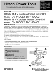
Hitachi 3.6 V Cordless Driver Drill
Model
DB 3DL2
D
MARKETING OBJECTIVE
The Model DB 3DL2 is a cordless driver drill equipped with a 3.6 V lithium-ion battery. The Model DB 3DL2 has
the following main features:
(1) Built-in verdischarge protection circuit and overcurrent protection circuit
(2) Equipped with newly developed lithium-ion battery (3.6 V, 1.5 Ah) that can be fully charged in 30 minutes.
(3) Flexibly changeable handle between L shape and straight shape
(4) Lightweight and compact
(5) White LED light
(6) Manual tightening mechanism. Screws are easily tightened manually thanks to the comfortable handle shape
and soft grip.
We aim to expand our market share with the new Model DB 3DL2.
APPLICATIONS
• Constructing electric facilities, assembling machines and servicing
• Tightening and loosening wood screws and machine screws
• Drilling into plastic and mild steel
SELLING POINTS
[NEW FEATURES]
Built-in verdischarge protection circuit and
overcurrent protection circuit
Lightweight and compact
White LED light
[SAME FEATURES AS THE CONVENTIONAL MODELS]
Equipped with lithium-ion battery
Flexibly changeable handle
Soft-grip handle
Manual tightening mechanism
21-stage clutch
Lock button
Blow-molded case
SPECIFICATIONS AND PARTS ARE SUBJECT TO CHANGE FOR IMPROVEMENT
International Sales Division
REMARK:
• For more information about HANDLING INSTRUCTIONS, visit our website at:
http://www.hitachi-koki.com/manual_view_export/
• Throughout this TECHNICAL DATA AND SERVICE MANUAL, a symbol(s) is(are) used in the place of
company name(s) and model name(s) of our competitor(s). The symbol(s) utilized here is(are) as follows:
Competitors
Symbols Utilized
C
Company Name
Model Name
DeWalt
DC600KA
CONTENTS
Page
SELLING POINTS -------------------------------------------------------------------------------------------------------------- 1
SPECIFICATIONS -------------------------------------------------------------------------------------------------------------- 4
1. Specifications------------------------------------------------------------------------------------------------------ 4
COMPARISON WITH SIMILAR PRODUCTS---------------------------------------------------------------------------- 5
1. Comparison of Specifications --------------------------------------------------------------------------------- 5
2. Comparison of Drilling and Fastening Performance per Charge ------------------------------------- 6
PRECAUTIONS ON SALES PROMOTION ------------------------------------------------------------------------------ 7
1. Safety Instructions ----------------------------------------------------------------------------------------------- 7
2. Inherent Drawbacks of Cordless Driver Drills Requiring Particular Attention during
Sales Promotion -------------------------------------------------------------------------------------------------- 8
REPAIR GUIDE---------------------------------------------------------------------------------------------------------------- 10
1. Precautions on Disassembly and Reassembly --------------------------------------------------------- 10
2. Precautions on Disassembly and Reassembly of the Battery Charger --------------------------- 18
STANDARD REPAIR TIME (UNIT) SCHEDULES-------------------------------------------------------------------- 19
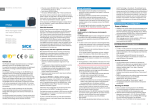
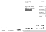
Assembly Diagram for DB 3DL2
SELLING POINTS
Built-in verdischarge protection circuit and
overcurrent protection circuit
The built-in verdischarge protection circuit and overcurrent protection circuit prevent any loss in battery
service life due to overdischarge (excessive use) and overcurrent (excessive load).
Lightweight and compact
The Model DB 3DL2 is compact and lightweight. It is easy to handle and convenient for operation in narrow spaces.
268 mm
210 mm
45 mm
134 mm
White LED light
The Model DB 3DL2 is equipped with a white LED light at the tip. This light can be used regardless of the
handle shape (L shape or straight shape).
• The light lights when the light switch is pushed.
see HANDLING INSTRUCTIONS
Light switch
White LED light
White LED light
Equipped with lithium-ion battery
The Type EBM 315 lithium-ion battery (3.6 V, 1.5 Ah) can be fully charged by the Model UC 3SFL Battery
Charger in just 30 minutes. The minus terminal has a cover to prevent improper short circuits. There is no
need to put on a battery cover as required for a conventional battery.
• Battery Charger Model UC 3SFL
• lithium-ion battery Type EBM 315
There is no need to put a
battery cover required for
a conventional battery.
Terminal cover
-1-
Flexibly changeable handle
The handle is flexibly changeable between the L shape and straight shape for various applications.
• Straight shape
Bent sections
• L shape
see HANDLING INSTRUCTIONS
Soft-grip handle
The handle is soft and slip-resistant. The end of the handle is also knobbed for a stable grip in manual
tightening.
The handle end is
knobbed for stable
gripping in manual
tightening.
Manual tightening mechanism
The Model DB 3DL2 can be used as a manual screwdriver. If a screw cannot be completely tightened with
the clutch setting, power off the Model DB 3DL2 and use it as a manual screwdriver by simply turning its
main body (maximum manual tightening torque: 5N·m {51 kgf·cm}).
• Power off the Model DB 3DL2 and use it as a
manual screwdriver by turning the main body.
see HANDLING INSTRUCTIONS
-2-
21-stage clutch
The torque can be finely adjusted by the 21-stage clutch.
• The tightening torque of this unit can be adjusted
according to the clutch dial position, at which the
clutch dial is set.
see HANDLING INSTRUCTIONS
Clutch dial
Triangle mark
Drill mark
Lock button
The lock button is provided to prevent inadvertent motor startup, even if the switch is mistakenly turned on.
• To activate the main switch lock, move the lock
switch to the “ LOCK ” position.
see HANDLING INSTRUCTIONS
Lock Switch
Unlock
Lock
“
LOCK “
Blow-molded case
The compact blow-molded case is convenient for carrying the tool.
-3-
SPECIFICATIONS
1. Specifications
Model
DB 3DL2
Item
Capacity
Screw driving
Machine screw------M 5 (1/5")
Wood screw ---------3.8 mm dia. x 38 mm (#8 x 1-1/2")
Drilling
Metal ------------------Mild steel ø 5 mm (13/64") [Thickness 1.0 mm (3/64")]
Tool retainer
6.35 mm (1/4") bit holder
Low: 200 min -1
High: 600 min -1
Rotation speed
Torque
Slip torque ------ 0.3 to 2.9 N·m (3 to 30 kgf·cm, 3 to 26 in-lbs.) [21 stages]
Max. torque----- 5 N·m (51 kgf·cm, 44 in-lbs.)
Type of motor
DC magnet motor
Type of switch
Tumbler switch with forward/reverse changeover pushing button
Enclosure
Body-------------------Glassfiber-reinforced nylon resin (black)
and thermoplastic elastomer (green)
Battery ----------------Polycarbonate resin (black)
Charger---------------ABS resin (black)
Type of battery
Sealed cylindrical lithium-ion storage battery
Nominal voltage
DC 3.6 V
Nominal life
Battery
Nominal capacity
(Type
EBM 315) Charging time
Charging/discharging: Approx. 500 times
1.5 Ah
30 minutes
(with standard accessory charger at ambient temperature of 20°C)
Charging
temperature
Charger
(Model UC 3SFL)
10°C to 40°C (50°F to 104°F)
• Overcharge prevention circuit:
A thermostat monitors the battery surface temperature and when
a rise in temperature is detected after the end of charging, the unit is
turned off automatically to prevent the battery from overcharge.
• Input capacity: 21 W
• Indication method: Pilot lamp indicates the charging state.
• Function: On ---------- During charging
Off ---------- Charging completed
Net
Main body (including Type EBM 315 battery) -------------- 0.4 kg (0.9 Ibs.)
Charger unit (including cord) ----------------------------------- 0.3 kg (0.7 Ibs.)
Gross
DB 3DL2 (2LCSK) (including Type EBM 315 battery) --- 1.8 kg (4.0 Ibs.)
Standard accessories
• Charger (UC 3SFL) ---------------------------------------------------------------1
• Battery (Type EBM 315) ---------------------------------------------------------2
• Phillips plus driver bit (No. 2) ---------------------------------------------------1
• Case-----------------------------------------------------------------------------------1
Weight
-4-
COMPARISON WITH SIMILAR PRODUCTS
1. Comparison of Specifications
Maker
Model
Item
Mild steel
Screw
driving
Wood screw
HITACHI
DB 3DL2
C
ø 5 mm (13/64")
Not indicated
3.8 mm dia. x 38 mm (#8 x 1-1/2")
Not indicated
Machine screw
M 5 (1/5")
Not indicated
Low
200 min -1
200 min -1
High
600 min -1
600 min -1
5 N·m (51 kgf·cm) (44 in-lbs.)
5 N·m (51 kgf·cm) (44 in-lbs.)
21 stages
8 stages
0.3 to 2.9 N·m
3 to 30 kgf·cm
(3 to 26 in-lbs.)
Not indicated
Equipped
Equipped
Driver chuck
Driver chuck
LED light
Equipped
Equipped
Soft-grip handle
Equipped
Equipped
Li-ion
Ni-Cd
Nominal capacity
1.5 Ah
1.2 Ah
Nominal voltage
3.6 V
3.6 V
Charging time*
30 min.
(Model UC 3SFL)
60 min.
Overall length
268 mm (10-9/32")
295 mm (11-39/64")
Overall height
45 mm (1-49/64")
67 mm (2-41/64")
Overall length
210 mm (8-17/64")
195 mm (7-43/64")
Overall height
134 mm (5-9/32")
170 mm (6-11/16")
45 mm (1-49/64")
46 mm (1-13/16")
0.45 kg (1.0 lbs.)
0.7 kg (1.5 lbs.)
Max. capacity
Drilling
(Superior specifications:
Rotation
speed
Max. torque
Slip torque
Spindle lock function
Tool tip mounting system
Dimensions
Battery
Battery type
Straightshape
L-shape
Width
Weight
*: Charging time may vary depending on the type of charger used.
-5-
)
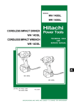
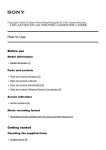
2. Comparison of Drilling and Fastening Performance per Charge
(Superior specifications:
Working capacity
Type of work
Maker
Model
*0 *250
0
ø 5 mm (13/64")
Mild steel
50
*500
*750
*1000
100
150
200
)
Drilling
speed
(sec./pc.)
T1.0 (3/64")
HITACHI
HSS drill bit
DB 3DL2
C
210
4.7
190
4.8
<High speed>
38 mm (1-1/2")
HITACHI
3.8 mm dia.
(#8)
Wood screw
DB 3DL2
70
6.5
60
6.7
American pine
C
<Low speed>
8 mm (5/16”)
Machine screw
M 5 (1/5")
HITACHI
DB 3DL2
C
*1000
0.8
760
0.8
<High speed>
[Working Capacity]
Without *: Number of holes or fasteners per charge
With *: Number of machine screws fastened per charge
The above table shows an example of test data obtained using the standard battery for this tool.
As actually measured values listed in the above table may vary depending on sharpness of the drill bit,
workpiece hardness (particularly in wood materials), moisture content of wood, charging condition, operator
skill, etc. This data should therefore only be used as a comparative guide.
-6-
PRECAUTIONS ON SALES PROMOTION
1. Safety Instructions
In the interest of promoting the safest and most efficient use of the Model DB 3DL2 Cordless Driver Drill by
all of our customers, it is very important when concluding a sale that the salesperson carefully ensure that
the buyer seriously recognizes the importance of the Handling Instructions, and fully understands the
meaning of precautions listed on the Caution Plate and Name Plate attached to each tool.
A. Handling instructions
Salespersons must be thoroughly familiar with the Handling Instructions in order to give pertinent advice to
the customer. In particular, they must have a thorough understanding of the precautions on using cordless
tools that differ from those of ordinary electric power tools.
(1) Before use, ensure that the unit is fully charged.
New units are not fully charged. Even if the units were fully charged at the factory, long periods of
inactivity, such as during shipping, cause the storage battery to lose its charge. Customers must be
instructed to fully charge the unit prior to use.
(2) When charging storage batteries, only use only the dedicated Model UC 3SFL Charger provided
with the tool.
Due to the designed rapid-charging feature (of about 30 minutes), the use of other battery chargers is
hazardous.
(3) Connect the charger to an AC power outlet only.
The use of any other power source (e.g., DC outlet, fuel powered generator) will cause the charger to
overheat and burn out.
(4) Do not use any voltage-increasing equipment (e.g., transformer) between the power source and
the charger.
Using the charger with voltage higher than that indicated on the unit will result in malfunction.
(5) Conduct battery charging at an ambient temperature range of 10°C to 40°C (50°F to 104°F).
Special temperature-sensitive devices are employed in the charger to permit rapid charging. Ensure
that customers are instructed to use the charger at the indicated ambient temperature range. At
temperature below 10°C (50°F) the thermostat will not function properly, and the storage battery may be
overcharged. At temperature above 40°C (104°F), the storage battery cannot be sufficiently charged.
The optimum temperature range is 20°C to 25°C (68°F to 77°F).
(6) The battery charger should not be used continuously.
Charging more than three storage batteries in succession at high ambient temperature will raise the
temperature of transformer coils and the temperature fuse inserted inside the transformer may
inadvertently melt. After charging one battery, please wait about 15 minutes before charging the next
battery.
(7) Do not insert foreign objects into the air vents on the charger.
The charger case is equipped with air vents to protect the internal electronic components from
overheating. Caution the customer not to allow foreign materials, such as metallic or flammable objects,
to be dropped or inserted into the air vents. This could cause electric shock, fire, or other serious
hazards.
-7-
(8) Do not attempt to disassemble the storage battery or the charger.
Special devices, such as a thermostat, are built into the storage battery and charger to permit rapid
charging. Incorrect parts replacement and/or wiring will cause malfunctions which could result in fire or
other hazards. Instruct the customer to bring these units to an authorized service center in the event
repair or replacement is necessary.
(9) Disposal of the storage battery (Type EBM 315)
Ensure that all customers understand that Type EBM 315 storage battery should be returned to the
Hitachi power tool sales outlet or authorized service center when no longer capable of being recharged
or repaired. If thrown into a fire, the battery may explode, or if discarded indiscriminately, leakage of the
cadmium compound contained in the battery may cause environmental pollution.
B. Caution plates
The following cautions are listed on the Name Plate attached to each Type EBM 315 storage battery.
[For Europe]
[For the USA and Canada]
2. Inherent Drawbacks of Cordless Driver Drills Requiring
Particular Attention during Sales Promotion
The cordless driver drill offers many advantages; it can be used in places where no power source is
available, the absence of a cord allows easy use, etc. However, any cordless tool has certain inherent
drawbacks.
Salespersons must be thoroughly familiar with these drawbacks in order to properly advise the customer in
the most efficient use of the tool.
A. Suggestions and precautions on efficient use of the tool
(1) Use the cordless driver drill for comparatively light work.
The motor output of battery driven cordless driver drills is rather low compared with conventional electric
power tools. Accordingly, they are not suitable for the continuous drilling of many holes in succession, or
for drilling into particularly hard material that imposes a heavy load. Salespersons should recommend
conventional electric power tools for such heavy work.
(2) Work requiring particularly strong torque should be conducted at low speed.
Instruct the customer to conduct work that requires particularly strong torque at low speed, as locking of
the motor may occur at high speed.
-8-
(3) Do not insert a foreign object into the body.
A foreign object inserted through a hole may cause failure. Please instruct customers to never insert a
foreign object into the main body of the tool.
(4) Avoid "Locking" of the motor.
Locking of the motor will generate an overload current that could result in motor burnout and/or rapid
battery deterioration. Salespersons should advise the customer to immediately release the switch and
stop operation if the motor becomes locked. (A jammed drill bit can be disengaged from the workpiece
material by setting the switch to reverse rotation, or by manually turning the main body of the tool.)
(5) Variation in amount of work possible per charge
Although the nominal chargeable capacity of the storage battery used with the Model DB 3DL2 is 1.5 Ah,
the actual capacity may vary within 10% of that value depending on ambient temperature during use
and charging, and the number of times the batteries have been recharged. It should be noted that other
factors that may affect the amount of work possible per charge are the working conditions (e.g., ambient
temperature, type and moisture content of the workpiece, sharpness of the drill bit) and the operational
skill of the user.
(6) Precautions on the use of HSS drill bits
For example, although the Model DB 3DL2 is designed for drilling capacities of 5 mm (13/64") in mild
steel, this capability is not as efficient as conventional electric power tools. In particular, the drill tends to
become locked when the drill bit penetrates a material. For this reason, the customer should be
cautioned to reduce the thrust on the main body of the drill when drilling completely through a material
to avoid locking the tool. Repeated locking of the drill causes excessive current to flow from the
batteries, thereby not only reducing the amount of work possible per charge, but also possibly resulting
in motor burnout.
B. Suggestions and precautions on efficient use of the charger and storage battery
If the Type EBM 315 storage battery is exposed to direct sunlight for an extended period or the tool has just
been operated for a long time, charging may not be possible if the battery temperature is above 40°C
(104°F). In such case, the customer should be advised to place the battery in a shaded area with good
airflow, and allow sufficient cooling before recharging. This phenomenon is common to all existing batteries
and chargers that employ temperature-sensitive overcharge protection devices. The cooling time
necessary before recharging can vary from a few minutes to about 30 minutes, depending on the load,
duration of use, and ambient temperature.
-9-
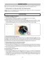
REPAIR GUIDE
Be sure to remove the storage batteries from the main body before servicing. Inadvertent triggering of the
switch with the storage battery connected imposes the danger of the motor accidently turning.
1. Precautions on Disassembly and Reassembly
[Bold] numbers in the descriptions below correspond to item numbers in the Parts List and exploded
assembly diagram for the Model DB 3DL2.
Disassembly
1. Removal of Handle (A).(B) Set
(1) Removal of the Clip [49] (2 pcs.).
Insert a flat-blade screwdriver in the indention of the Clip [49] and remove the Clip [49].
(2) Remove the Tapping Screw (W/Flange) D4 x 20 (Black) [43].
(3) Grip the battery insertion part and open Handle (A).(B) Set [50]. Since there are latches in Handle
(A).(B) Set [50], it is hard to open. Open Handle (A).(B) Set [50] from the LED button side. Then
remove the Button [44]. Do not remove the Steel Ball D3 [36] from Handle (A).(B) Set [50].
• Removal of the Clip
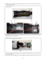
2. Removal of Housing (A).(B) Set
Remove the two Click Plate [37], Pan Hd. Tapping Screw D3 x 8 [34] and Handle Cover [39]. Since there
are latches in Housing (A).(B) Set [33], it is hard to open. Open Housing (A).(B) Set [33] from the Shift
Knob [38] side. After opening Housing (A).(B) Set [33], all internal parts (of the drive unit) can be removed.
Pull out the drive unit (consisting of the gear unit, Motor DC 3.6V [31] and power supply unit).
3. Disassembly of the drive unit (internal parts)
(1) Remove the Shift Arm [13] from the Gear Box Ass’y [1].
(2) Pull up the Motor DC 3.6V [31] and remove it from the Gear Box Ass’y [1]. Remove the two Machine
Screw (W/Sp. Washer) M2.6 x 6 [32], then remove the Motor Spacer [30] from the Motor DC 3.6V [31].
(3) Pull up the Switch (W/Lock) [41] and remove it from the Motor DC 3.6V [31]. If it is difficult to remove,
use a flat-blade screwdriver.
4. Disassembly of the gear unit
(1) Removal of the gear
Take out Washer (A) [29], First Ring Gear [28], Planet Gear (A) Set (3 pcs.) [27], Pinion (B) [26], Slide
Ring Gear [25], Planet Gear (B) Set (3 pcs.) [24] and Pinion (C) [23] one by one. Then remove the two
Needle [18] from the Gear Case [12]. Take out Washer (B) [22], Ring Gear [21], Planet Gear (C) Set (3
pcs.) [20], Carrier [19], Needle Roller Set (6 pcs.) [17], Lock Ring [16], three Steel Ball D3 [15] and Pin
Set (3 pcs.) [14] one by one.
-10-
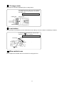
(2) Removal of Guide Sleeve (A) [6]
Remove the Retaining Ring [3], Washer (D) [4], Guide Spring [5] and Guide Sleeve (A) [6] in order by
following the procedure shown in Fig. 1-1 to 1-4.
Then slowly raise the other side of the retaining ring with the small flat-blade screwdriver until it is free.
Avoid quickly raising the retainer ring or it may fly out forcefully.
Socket
Small flat-blade
screwdriver
Washer (D) [4]
Retaining Ring [3]
Guide Sleeve (A) [6]
Fig.1-2
Fig.1-1
Hold the body and adjust the gap of the Retaining Ring [3]
to the groove of socket, then insert a small flat-blade
screwdriver into the groove at an angle.
Press down Washer (D) [4] with the small flat-blade
screwdriver.
Fig. 1-3
Fig. 1-4
Slide the small flat-blade screwdriver under one side of
the gap of the Retaining Ring [3].
Slowly raise the retaining ring using the end face of
Guide Sleeve (A) [6] as a fulcrum.
(3) Disassembly of the clutch unit
Remove the Clutch Dial [7] after removal of Guide Sleeve (A) [6]. Turn the Nut [8] counterclockwise and
remove it from the Gear Case [12]. Remove the Spring [9] and Washer (D) [10] from the Gear Case [12].
NOTE: Do not remove the Gear Case [12].
5. Disassembly of the power supply unit
The internal wires of the Switch (W/Lock) [41] and Terminal [46] are soldered to the Printed Circuit Board
[45]. Unsolder and remove the parts.
NOTE: Do not remove the Printed Circuit Board [45].
-11-
Reassembly
Conduct reassembly by reversing the disassembly procedures. However, special attention should be given
to the following items.
1. Reassembly of the power supply unit
• Perform wiring according to the wiring diagram
Switch (W/Lock) [41]
Printed Circuit Board [45]
Terminal [46]
2. Reassembly of the clutch unit
(1) Mount Washer (D) [10] and the Spring [9] to the Gear Case [12].
(2) Mount the Nut [8] to the Gear Case [12].
Align register mark (i) on the Nut [8] with the register mark on the Gear Case [12]. Turn the Nut [8] about 11/12 turns clockwise so that register mark (ii) on the Nut [8] is aligned with the register mark on the Gear
Case [12]. Check that the Y surface of the Nut [8] is aligned with the Z surface of the Gear Case [12].
• Mount the Nut to the Gear Case
Mounting start position
Mounting end position
Register mark (i)
Register mark (ii)
Register mark
Register mark
Nut [8]
Y surface
Y surface
Z surface
Gear Case [12]
Z surface
Nut [8]
Gear Case [12]
-12-
3. Reassembly of the manual tightening mechanism
(1) Mount the Lock Ring [16] to the Gear Case [12]
so that the protrusion of the Lock Ring [16] is
aligned with the concave portion of the Gear Case
[12]. At this time, mount the Lock Ring [16] so that
the stepped protrusion faces forward.
(2) Mount the Needle Roller Set (6 pcs.) [17].
• Mount the Lock Ring and the Needle Roller Set
Lock Ring [16]
Needle Roller Set
(6pcs.) [17]
Concave portion
NOTE: Do not apply grease to the Lock Ring [16]
and Needle Roller Set (6 pcs.) [17].
Gear Case [12]
Protrusion
Stepped portion
4. Reassembly of the deceleration mechanism
(1) Apply a sufficient amount of grease (Hitachi Motor Grease No. 29) to the engaging portions of each gear
and the needle roller unit, and the contacting surfaces of the steel balls of the ring gear.
(2) Mount the parts from the Pin Set (3 pcs.) [14] to Washer (A) [29] to the parts assembled in the following
(b) in order.
(a) Mount the Pin Set (3 pcs.) [14] and Steel Ball D3 [15].
(b) Pay attention to the mounting direction of the Ring Gear [21], Carrier [19], Pinion (C) [23] and Pinion
(B) [26].
• Mount the parts
Planet Gear (C) Set [20]
Gear Case [12]
Needle [18]
Pin Set [14]
Steel Ball D3 [15]
Lock Ring [16]
Carrier [19]
Ring Gear [21]
Washer (B) [22]
Pinion (C) [23]
Planet Gear (B) Set [24]
Slide Ring Gear [25]
Pinion (B) [26]
Planet Gear (A) Set [27]
Needle Roller Set [17]
First Ring Gear [28]
Washer (A) [29]
-13-
5. Reassembly of the drive unit
(1) Pay attention to the mounting direction of the Motor DC 3.6V [31] and Switch (W/Lock) [41]. Insert the
red marked terminal of the Motor DC 3.6V [31] into the terminal on the lock switch side of the Switch
(W/Lock) [41]. At this time, insert each terminal of the Motor DC 3.6V [31] between the terminal and the
convex portion of the Switch (W/Lock) [41].
• Insert the red marked terminal of the motor
Lock switch
Motor DC 3.6V [31]
Switch (W/Lock) [41]
Red mark
Enlarged section A
Terminal
Terminal
Terminal
Convex portions
(2) Mount the Motor Spacer [30] to the Motor DC 3.6V [31] with the two Machine Screw (W/Sp. Washer)
M2.6 x 6 [32]. Do not mistake the head and tail of the Motor Spacer [30]. Note that there is no
difference in circumferential direction. Pay attention to the mounting direction when mounting the Motor
DC 3.6V [31] to the Gear Box Ass’y [1].
• Mount the motor spacer
Convex portion
Shift Arm [13]
Motor Spacer [30]
Motor DC 3.6V [31]
Gear Case [12]
Switch (W/Lock) [41]
Machine Screw (W/Sp. Washer) M2.6 x 6 [32]
-14-
(3) Mount the Shift Arm [13] to the Shift Knob [38] by using a small flat-blade screwdriver to completely
push the Shift Arm [13] into the groove of the Shift Knob [38]. Insert the end of the Shift Arm [13] into
the hole of the Gear Case [12] and fit it in the groove of the Slide Ring Gear [25]. Pay attention to the
direction of the Gear Case [12]. Do not mount the Shift Arm [13] facing downward.
• Mount the Shift Arm
Shift Knob [38]
Slide Ring Gear [25]
Shift Arm [13]
Groove
Gear Case [12]
6. Mounting the Clutch Dial to the Gear Case
The Nut [8] has three protrusions. One
of these protrusions is wider than the
others. The Clutch Dial [7] has three
concave portions. One of these concave
portions is wider than the others. Mount
the Nut [8] to the Clutch Dial [7] by
aligning the wider protrusion of the Nut
[8] with the wider concave portion of the
Clutch Dial [7]. (The wider concave
portion in the Clutch Dial [7] is at the
position indicated with "1" on the outside
of the Clutch Dial [7].)
• Mounting the clutch dial
Indicated with "1"
Clutch Dial [7]
Wider
Concave portion
Wider Protrusion
Nut [8]
Protrusion
Protrusion
Concave portion
Concave portion
7. Reassembly of the housing unit
(1) Mount the Click Spring [40] to Housing (A).(B) Set [33] so that the convex portion of the Click Spring
[40] can be seen. Apply grease (Hitachi Motor Grease No. 29) to the Click Spring [40].
• Mount the click spring
Housing (A).(B) Set [33]
Click Spring [40]
Convex portion
-15-
(2) Mount the LED to Housing (A).(B) Set [33]. Put the internal wires of the LED between the ribs of
Housing (A).(B) Set [33].
• Mount the LED
B
A
Rib
A
B
Rib
(3) Mount the drive unit to Housing (A).(B) Set [33]. Put the internal wires of the LED and Switch (W/Lock)
[41] through the rib of the housing.
• Mount the drive unit and put the internal wires
Rib
(4) Close Housing (A).(B) Set [33] and mount the Handle Cover [39]. Tighten the four Pan Hd. Tapping
Screw D3 x 8 [34].
(5) Mount the two Click Plate [37] to Housing (A).(B) Set [33] and apply grease (Hitachi Motor Grease No. 29).
-16-
(6) Check for proper operation of the Clutch Dial [7].
When the reassembly procedure is completed up to step (5), ensure that every indication on the Clutch
Dial [7] from number "1" to the drill mark "
" can be aligned with the triangle mark on Housing
(A).(B) Set [33], respectively, and that the Clutch Dial [7] turns moderately. If any indication on the
Clutch Dial [7] cannot be aligned with the triangle mark on Housing (A).(B) Set [33], correctly remount
the improperly mounted Clutch Dial [7] according to step “2. Reassembly of the clutch unit (2).”
8. Reassembly of the handle unit
Mount either of Handle (A).(B) Set [50] to Housing (A).(B) Set [33]. Fit the Printed Circuit Board [45],
Terminal [46] and Terminal Support [47] in the grooves of the handle. Mount the Button [44] to the switch
of the Printed Circuit Board [45] and close Handle (A).(B) Set [50]. Tighten the Tapping Screw (W/Flange)
D4 x 20 (Black) [43]. Mount the two Clip [49] to the groove of Handle (A).(B) Set [50] by using a flat-blade
screwdriver.
• Mount either of handle (A).(B) set
Printed Circuit Board [45]
Terminal [46]
9. Mounting Guide Sleeve (A)
Put the Steel Ball D3.5 [11] in the hole of the
socket. Mount Guide Sleeve (A) [6], the Guide
Spring [5], and Washer (D) [4] in sequence. Fit
the Retaining Ring [3] in the groove of the
socket by using J295 jigs (A) and (B) for
retaining ring as illustrated.
NOTE: Be sure to replace the Retaining
Ring [3] with a new one because the
Retaining Ring [3] may be deformed
when removed. Guide Sleeve (A) [6]
may come off if the deformed
Retaining Ring [3] is used again.
Button [44]
Terminal Support [47]
• Fit the retaining ring in the groove of the socket
Push down.
Retaining Ring [3]
J295 jig (B)
for retaining ring
Washer (D) [4]
J295 jig (A)
for retaining ring
-17-
10. Other precautions on reassembly
After completing reassembly, set the storage battery and check for operation.
(1) Check the rotating direction of Guide Sleeve (A) [6].
Press the (R) side of the Switch (W/Lock) [41] to check that Guide Sleeve (A) [6] rotates clockwise as
viewed from behind.
(2) Check for proper operation of the Shift Knob [38].
Check that the speed properly changes between high and low by shifting the Shift Knob [38]. If the
speed does not change properly or moderately, correctly remount the improperly mounted Shift Knob
[38] according to step “5. Reassembly of the drive unit (3).”
(3) Check that the LED goes on and off by pushing the Button [44]. (Although the LED cannot react when
turned on/off too quickly, this is no failure.)
(4) Check for flexible change of the handle between the L-shape and straight shape.
Screw Tightening Torque
• Machine Screw (W/Sp. Washer) M2.6 x 6 [32]---------------------------- 0.1 to 0.29 N·m {1 to 3 kgf·cm}
• Pan Hd. Tapping Screw D3 x 8 [34] ----------------------------------------- 0.49 to 0.64 N·m {5 to 6.5 kgf·cm}
• Tapping Screw (W/Flange) D4 x 20 (Black) [43]-------------------------- 1.5 to 2.5 N·m {15 to 25 kgf·cm}
2. Precautions on Disassembly and Reassembly of the Battery Charger
Please refer to the Technical Data and Service Manual for precautions on disassembly and reassembly of
the Battery Charger Model UC 3SFL.
-18-
STANDARD REPAIR TIME (UNIT) SCHEDULES
MODEL
Variable
Fixed
10
20
30
Work Flow
Housing
(A).(B) Set
DB 3DL2
General assembly
Housing
(A).(B) Set
Click Plate
Guide
Sleeve Set
Motor
Shift Knob
Switch
Gear Box
Ass'y
Clutch Dial
Nut
Spring
Gear Case
Shift Arm
Lock Ring
Carrier
Planet Gear
(C) Set
Ring Gear
Pinion (C)
Planet Gear
(B) Set
Slide Ring
Gear
Pinion (B)
Planet Gear
(A) Set
First Ring
Gear
-19-
40
50
60 min.
LIST NO. H870
CORDLESS DRIVER DRILL
Model DB 3DL2
2010㨯6㨯14
(E1)
1
2
4
3
5
502
501
501
503
6
7
8
9
10
19
20
11
21
12
13
22
23
14
24
15
25
18
26
16
17
27
28
29
30
31
34
42
37
32
36
43
40
33
41
38
44
39
45
46
34
47
35
37
49
48
36
50
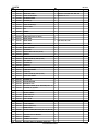
PARTS
ITEM
NO.
DB 3DL2
CODE NO.
DESCRIPTION
NO.
USED
REMARKS
*
1
332-759
GEAR BOX ASS'Y
1
INCLUD. 3-30
*
1
332-758
GEAR BOX ASS'Y
1
INCLUD. 3-30 FOR CHN, SIN, VIE
2
320-085
GUIDE SLEEVE SET
1
INCLUD. 3-6, 11
3
315-984
RETAINING RING
1
4
315-983
WASHER (D)
1
5
320-409
GUIDE SPRING
1
6
319-921
GUIDE SLEEVE (A)
1
7
332-762
CLUTCH DIAL
1
8
326-341
NUT
1
9
326-340
SPRING
1
10
326-339
WASHER (D)
1
11
319-535
STEEL BALL D3.5 (10 PCS.)
1
*
12
332-761
GEAR CASE
1
*
12
332-760
GEAR CASE
1
13
326-345
SHIFT ARM
1
14
326-338
PIN SET (3 PCS.)
3
15
317-788
STEEL BALL D3
3
16
326-323
LOCK RING
1
17
326-324
NEEDLE ROLLER SET (6PCS.)
6
18
326-329
NEEDLE
2
19
326-325
CARRIER
1
20
326-327
PLANET GEAR (C) SET (3 PCS.)
3
21
326-326
RING GEAR
1
22
326-328
WASHER (B)
2
23
332-768
PINION (C)
1
24
332-766
PLANET GEAR (B) SET (3 PCS.)
3
25
332-767
SLIDE RING GEAR
1
26
332-765
PINION (B)
1
27
326-335
PLANET GEAR (A) SET (3 PCS.)
3
28
326-334
FIRST RING GEAR
1
29
332-764
WASHER (A)
1
30
332-763
MOTOR SPACER
1
31
332-755
MOTOR DC 3.6V
1
32
330-755
MACHINE SCREW (W/SP. WASHER) M2.6 X 6
2
33
332-754
HOUSING (A). (B) SET
1
34
984-319
PAN HD. TAPPING SCREW D3 X 8
4
HITACHI LABEL
1
35
36
317-788
STEEL BALL D3
4
37
326-315
CLICK PLATE
2
38
332-757
SHIFT KNOB
1
39
332-975
HANDLE COVER
1
40
326-309
CLICK SPRING
1
41
332-769
SWITCH (W/LOCK)
1
NAME PLATE
1
1
42
*
43
302-086
TAPPING SCREW (W/FLANGE) D4 X 20 (BLACK)
44
332-756
BUTTON
1
45
332-770
PRINTED CIRCUIT BOARD
1
46
332-771
TERMINAL
2
47
326-316
TERMINAL SUPPORT
1
48
326-299
BATTERY EBM 315 (EUROPE, AUS, NZL)
2
-2-
*ALTERNATIVE PARTS
FOR CHN, SIN, VIE
6 - 10
PARTS
ITEM
NO.
DB 3DL2
CODE NO.
DESCRIPTION
NO.
USED
*
48
326-263
BATTERY EBM 315 (USA, CAN)
2
*
48
330-757
BATTERY EBM 315 (CHN)
2
49
326-318
CLIP
1
*
50
332-752
HANDLE (A). (B) SET (GREEN)
1
*
50
332-588
HANDLE (A) (B) SET (BLACK)
1
6 - 10
*ALTERNATIVE PARTS
REMARKS
-3-
STANDARD ACCESSORIES
ITEM
NO.
CODE NO.
DB 3DL2
DESCRIPTION
NO.
USED
*
501
992-671
+ DRIVER BIT (B) NO. 2 50L
1
*
501
983-006
+ DRIVER BIT NO. 2 65L
1
CHARGER (MODEL UC 3SFL)
1
332-844
CASE
1
502
503
REMARKS
FOR CHN, SIN, VIE
OPTIONAL ACCESSORIES
ITEM
NO.
CODE NO.
DESCRIPTION
NO.
USED
601
326-665
HOLSTER
1
602
992-670
+ DRIVER BIT (B) NO. 1 50L
1
603
992-672
+ DRIVER BIT (B) NO. 3 50L
1
604
992-675
- DRIVER BIT (B) 4MM X 50
1
605
992-676
- DRIVER BIT (B) 5MM X 50
1
606
992-677
- DRIVER BIT (B) 6MM X 50
1
607
321-823
DRILL CHUCK AND ADAPTER SET
1
608
307-543
CHUCK ADAPTER
1
609
987-575
CHUCK WRENCH FOR 10VLB-D, 10VLR-D
1
-4-
*ALTERNATIVE PARTS
REMARKS
INCLUD. 608, 609
Printed in Japan
(100614N)
6 - 10