1
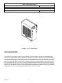
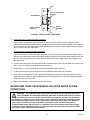
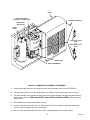
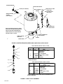
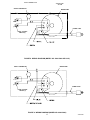
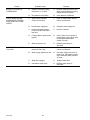
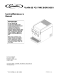
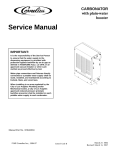
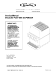
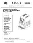
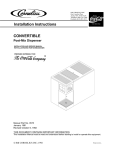
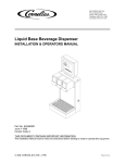
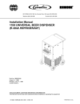
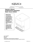
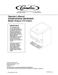
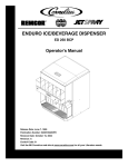
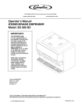
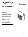
VA 13
CARBONATOR
Service Manual
IMPORTANT:
It is the responsibility of the Service Person
to ensure that the water supply to the
dispensing equipment is provided with
protection against backflow by an air gap as
defined in ANSI/ASME A112. 1.2-1979; or an
approved vacuum breaker or other such
method as proved effective by test.
Water pipe connections and fixtures directly
connected to a potable water supply shall be
sized, installed, and maintained according to
Federal, State, and Local laws.
When installing in an area regulated by the
City of Los Angeles Plumbing and/or
Mechanical Codes, a City of Los Angeles
approved reduced pressure principle
backflow preventer shall be installed on each
potable water supply to each carbonator.
Manual Part No. 318511005
EIMI Cornelius Inc.; 1982-1997
Control Code C
April 1,1982
Revised: March 11, 1997
TABLE OF CONTENTS
Page
SAFETY INFORMATION . . . . . . . . . . . . . . . . . . . . . . . . . . . . . . . . . . . . . . . . . . . . . . . . . . . .
1
RECOGNIZE SAFETY INFORMATION . . . . . . . . . . . . . . . . . . . . . . . . . . . . . . .
1
UNDERSTAND SIGNAL WORDS . . . . . . . . . . . . . . . . . . . . . . . . . . . . . . . . . . . .
1
FOLLOW SAFETY INSTRUCTIONS . . . . . . . . . . . . . . . . . . . . . . . . . . . . . . . . .
1
CO2 (CARBON DIOXIDE) WARNING . . . . . . . . . . . . . . . . . . . . . . . . . . . . . . . .
1
SHIPPING, STORING, OR RELOCATING UNIT . . . . . . . . . . . . . . . . . . . . . . .
1
GENERAL INFORMATION . . . . . . . . . . . . . . . . . . . . . . . . . . . . . . . . . . . . . . . . . . . . . . . . . .
3
TO THE USER OF THIS MANUAL . . . . . . . . . . . . . . . . . . . . . . . . . . . . . . . . . . . . . . .
3
CLAIMS INSTRUCTIONS . . . . . . . . . . . . . . . . . . . . . . . . . . . . . . . . . . . . . . . . . . . . . .
3
WARRANTY REFERENCE INFORMATION . . . . . . . . . . . . . . . . . . . . . . . . . . . . . . .
3
DESIGN DATA . . . . . . . . . . . . . . . . . . . . . . . . . . . . . . . . . . . . . . . . . . . . . . . . . . . . . . . .
3
UNIT DESCRIPTION . . . . . . . . . . . . . . . . . . . . . . . . . . . . . . . . . . . . . . . . . . . . . . . . . . .
4
THEORY OF OPERATION . . . . . . . . . . . . . . . . . . . . . . . . . . . . . . . . . . . . . . . . . . . . . .
5
SERVICE AND MAINTENANCE . . . . . . . . . . . . . . . . . . . . . . . . . . . . . . . . . . . . . . . . . . . . .
7
PREPARING UNIT FOR SHIPPING OR RELOCATING . . . . . . . . . . . . . . . . . . . . .
7
PERIODIC CLEANING . . . . . . . . . . . . . . . . . . . . . . . . . . . . . . . . . . . . . . . . . . . . . . . . .
8
LUBRICATION . . . . . . . . . . . . . . . . . . . . . . . . . . . . . . . . . . . . . . . . . . . . . . . . . . . . . . . .
8
ADJUSTMENTS . . . . . . . . . . . . . . . . . . . . . . . . . . . . . . . . . . . . . . . . . . . . . . . . . . . . . . .
8
ADJUSTING CARBONATOR CO2 REGULATOR . . . . . . . . . . . . . . . . . . . . . .
8
ADJUSTING CARBONATOR TANK LIQUID LEVELS . . . . . . . . . . . . . . . . . . . . . . .
8
WATER PUMP YEARLY MAINTENANCE (OR AFTER WATER SYSTEM
DISRUPTIONS) . . . . . . . . . . . . . . . . . . . . . . . . . . . . . . . . . . . . . . . . . . . . . . . . . . . . . . .
9
SERVICING WATER PUMP WATER INLET STRAINER SCREEN . . . . . . .
10
SERVICING LIQUID DUAL CHECK VALVE . . . . . . . . . . . . . . . . . . . . . . . . . . .
10
THE VENTED DUAL-CHECK VALVE ASSEMBLY . . . . . . . . . . . . . . . . . . . . .
13
REPAIR AND REPLACEMENT . . . . . . . . . . . . . . . . . . . . . . . . . . . . . . . . . . . . . . . . . .
13
LEVEL CONTROL SWITCH(S) . . . . . . . . . . . . . . . . . . . . . . . . . . . . . . . . . . . . . .
13
SAFETY THERMOSTAT . . . . . . . . . . . . . . . . . . . . . . . . . . . . . . . . . . . . . . . . . . . .
13
WATER PUMP . . . . . . . . . . . . . . . . . . . . . . . . . . . . . . . . . . . . . . . . . . . . . . . . . . . .
14
WATER PUMP MOTOR . . . . . . . . . . . . . . . . . . . . . . . . . . . . . . . . . . . . . . . . . . . .
14
VENTED DUAL–CHECK VALVE ASSEMBLY . . . . . . . . . . . . . . . . . . . . . . . . . .
15
TROUBLESHOOTING. . . . . . . . . . . . . . . . . . . . . . . . . . . . . . . . . . . . . . . . . . . . . . . . . . . . . .
19
WATER PUMP MOTOR WILL NOT OPERATE. . . . . . . . . . . . . . . . . . . . . . . . . . . . .
19
WATER PUMP MOTOR WILL NOT SHUT OFF. . . . . . . . . . . . . . . . . . . . . . . . . . . .
19
ERRATIC CYCLING OF CARBONATOR. . . . . . . . . . . . . . . . . . . . . . . . . . . . . . . . . .
20
WATER PUMP MOTOR OPERATES BUT WATER PUMP DOES NOT PUMP
WATER. . . . . . . . . . . . . . . . . . . . . . . . . . . . . . . . . . . . . . . . . . . . . . . . . . . . . . . . . . . . . . .
20
WATER PUMP CAPACITY TOO LOW. . . . . . . . . . . . . . . . . . . . . . . . . . . . . . . . . . . .
20
WARRANTY . . . . . . . . . . . . . . . . . . . . . . . . . . . . . . . . . . . . . . . . . . . . . . . . . . . . . . . . . . . . . .
21
LIST OF FIGURES
FIGURE 1. VA 13 CARBONATOR . . . . . . . . . . . . . . . . . . . . . . . . . . . . . . . . . . . . . . . .
4
FIGURE 2. LEVEL CONTROL SWITCHES . . . . . . . . . . . . . . . . . . . . . . . . . . . . . . . .
9
FIGURE 3. CARBONATOR ASSEMBLY COMPONENTS . . . . . . . . . . . . . . . . . . .
11
i
318511005
TABLE OF CONTENTS (cont’d)
Page
LIST OF FIGURES (CONT’D)
FIGURE 4. WATER STRAINER SCREEN AND LIQUID DUAL CHECK VALVE .
12
FIGURE 5. CHECK VALVE ASSEMBLY . . . . . . . . . . . . . . . . . . . . . . . . . . . . . . . . . .
12
FIGURE 6. VENTED DUAL CHECK VALVE LOCATION . . . . . . . . . . . . . . . . . . . .
16
FIGURE 7. BARBED VENTED POSITION . . . . . . . . . . . . . . . . . . . . . . . . . . . . . . . .
16
FIGURE 8. WIRING DIAGRAM (MODEL NO. 416411000 AND 1621) . . . . . . . . .
17
FIGURE 9. WIRING DIAGRAM (MODEL NO. 496411000) . . . . . . . . . . . . . . . . . . .
17
FIGURE 10. WIRING DIAGRAM (MODEL NO. 496411020) . . . . . . . . . . . . . . . . .
18
FIGURE 11. WIRING DIAGRAM (MODEL NO. 496411040) . . . . . . . . . . . . . . . . . .
18
LIST OF TABLES
TABLE 1. DESIGN DATA . . . . . . . . . . . . . . . . . . . . . . . . . . . . . . . . . . . . . . . . . . . . . . .
318511005
ii
3
SAFETY INFORMATION
Recognize Safety Information
This is the safety-alert symbol. When you see this
symbol on our machine or in this manual, be alert to
the possibility of personal injury.
Follow recommended precautions and safe operating
practices.
Understand Signal Words
A signal word - DANGER, WARNING, OR CAUTION
is used with the safety-alert symbol. DANGER identifies the most serious hazards.
Safety signs with signal word DANGER or WARNING
are typically near specific hazards.
General precautions are listed on CAUTION safety
signs. CAUTION also calls attention to safety messages in this manual.
DANGER
WARNING
CAUTION
Follow Safety Instructions
Carefully read all safety messages in this manual and on your machine safety signs. Keep safety signs in
good condition. Replace missing or damaged safety signs. Learn how to operate the machine and how to
use the controls properly. Do not let anyone operate the machine without instructions. Keep your machine in
proper working condition. Unauthorized modifications to the machine may impair function and/or safety and
affect the machine life.
CO2 (Carbon Dioxide) Warning
CO2 Displaces Oxygen. Strict Attention must be observed in the prevention of CO2 (carbon dioxide)
gas leaks in the entire CO2 and soft drink system. If a CO2 gas leak is suspected, particularly in a
small area, immediately ventilate the contaminated area before attempting to repair the leak. Personnel exposed to high concentration of CO2 gas will experience tremors which are followed rapidly by
loss of consciousness and suffocation.
Shipping, Storing, Or Relocating Unit
CAUTION: All water must be purged from the Unit if exposed to freezing temperature. A freezing ambient temperature will cause residual water remaining inside the Unit to freeze resulting in damage to
internal components of the Unit.
1
318511005
THIS PAGE LEFT BLANK INTENTIONALLY
318511005
2
GENERAL INFORMATION
TO THE USER OF THIS MANUAL
This Manual is a guide for servicing and maintaining this equipment. Refer to Table Of Contents for page location of detailed information pertaining to questions that may arise. A parts manual (P/N 318511005) for this
equipment is available upon request.
This Unit must be serviced by a qualified Service Person. This Unit contains no User serviceable parts.
CLAIMS INSTRUCTIONS
Claims: In the event of shortage, notify the carrier as well as IMI Cornelius immediately. In the event of damage, notify the carrier. IMI Cornelius is not responsible for damage occurring in transit, but will gladly
render assistance necessary to pursue your claim. Merchandise must be inspected for concealed damage within 15 days of receipt.
WARRANTY REFERENCE INFORMATION
Warranty Registration Date
(to be filled out by customer)
Unit Part Number:
Serial Number:
Install Date:
Local Authorized
Service Center:
DESIGN DATA
Table 1. Design Data
Model Numbers
115 VAC Unit (With liquid dual check valve)
115 VAC Unit (With vented dual check valve)
230 VAC Unit (With liquid dual check valve)
230 VAC Unit (With liquid dual check valve)
230 VAC Unit (With liquid dual check valve)
Overall Dimensions:
Width
Height
Depth
416411000
1621
496411000
496411020
496411040
6-3/8 inches
15 inches
14 inches
Weight:
Dry
Shipping
28-3/4 pounds
30-1/4 pounds
Ambient Operating Temperature
40° F to 100° F
3
318511005
Table 1. Design Data (cont’d)
Maximum Operating CO2 Pressure
125 PSI
Electrical Requirements:
Operating Voltage and Current Draw
See Unit Nameplate
FIGURE 1. VA 13 CARBONATOR
UNIT DESCRIPTION
The carbonator is a compact Unit that may be installed in a remote location from where its carbonated water
outlet is to be connected to a post-mix dispenser or a system. The purpose of the Unit is to mix plain water and
carbon dioxide (CO2) gas which results in and provides carbonated water for a post-mix dispenser or a system.
The Unit consists basically of a water pump, motor, and a carbonated water tank. The water pump has a liquid
dual check valve (Unit Model No. 416411000, 496411000, 496411020, and 496411040 or a Vented Dual Check
Valve (Unit Model No. 1621) on its outlet to prevent carbonated water from back flowing into the city water system. The Vented Dual Check Valve vents water and possibly CO2 gas out of a vent port on failure of the primary
check valves. Should such venting occur, the primary check valve should be replaced. The Unit CO2 inlet has a
single check valve to prevent carbonated water back flow into the CO2 regulator.
318511005
4
THEORY OF OPERATION
A CO2 cylinder delivers carbon dioxide (CO2) gas through an adjustable CO2 regulator to the carbonated water
tank. At the same time, plain water is pumped into the carbonated water tank by the water pump and is carbonated by CO2 gas also entering the tank. Carbonated water enters the tank until the weight of the water in the
tank forces the tank and balance control mechanism down to activate the level control switches. Activating the
level control switches disrupts electrical power to and stops the water pump motor. As carbonated water is dispensed from the tank, the tank becomes lighter allowing the tank and balance control mechanism to rise which
again activates the level control switches. Activating the level control switches restores electrical power to the
water pump motor allowing the carbonated water tank to be replenished.
5
318511005
THIS PAGE LEFT BLANK INTENTIONALLY
318511005
6
SERVICE AND MAINTENANCE
This section describes service and maintenance procedures to be performed on the Unit.
IMPORTANT: Only qualified personnel should service internal components or electrical wiring.
CAUTION: This Unit must not be installed in an unsheltered outdoor location where it will
be exposed to the elements.
WARNING: Disconnect electrical power to the carbonator to prevent personal injury before
attempting any internal maintenance.
CAUTION: Never operate the carbonator with the water inlet supply line shutoff valve
closed. “Dry running ” the water pump will burn out the pump. A pump damaged in this
manner is not covered by warranty.
CAUTION: To prevent a fire hazard, no object should be placed or stored on top of the Unit.
PREPARING UNIT FOR SHIPPING OR RELOCATING
CAUTION: Before shipping, storing, or relocating the carbonator, all water must be purged
from inside the carbonator. A freezing ambient environment will cause residual water
remaining inside the carbonator to freeze resulting in damage to it’s internal components.
Damage of this type will void the Factory warranty.
Perform the following procedure to purge water from inside the carbonator.
1. Disconnect electrical power from the Unit.
2. Close the plain water inlet line shutoff valve.
3. Disconnect plain water inlet line from the Unit.
4. Dispense from the Post-Mix Dispenser dispensing valve until all carbonated water has been dispensed
from the carbonated water tank.
5. Shut off CO2 supply to the Unit, then disconnect CO2 inlet supply line from the Unit.
6. Connect filtered dry compressed air (50-psi max) to the Unit water inlet. DO NOT USE CO2 GAS WHICH
COULD CAUSE A HEALTH HAZARD.
7. Dispense from Post-Mix Dispenser dispensing valve until all residual water has been blown from Unit and
lines.
8. Disconnect filtered dry compressed air from Unit water inlet.
7
318511005
9. Disconnect carbonated water outlet line from the Unit.
10. The Unit is now ready for shipping or relocating.
PERIODIC CLEANING
Clean all external surfaces of the Unit with a sponge. Rinse out the sponge with clean water, then wring excess
water out of the sponge and wipe off external surfaces of the Unit. Wipe the Unit dry with a clean soft cloth. DO
NOT USE ABRASIVE CLEANERS.
LUBRICATION
The water pump motor bearings must be oiled periodically. Refer to oiling instructions on the pump motor. DO
NOT OVER OIL.
ADJUSTMENTS
ADJUSTING CARBONATOR CO2 REGULATOR
To readjust the CO2 regulator to a lower setting, loosen adjusting screw lock nut, then turn the adjusting screw
to the left (counterclockwise) until pressure gage reads 5-psi lower than new setting will be. Turn the adjusting
screw to the right (clockwise) until the gage registers a new setting, then tighten the lock nut. Adjust the carbonator CO2 regulator to a nominal 80-psi.
ADJUSTING CARBONATOR TANK LIQUID LEVELS
(see Figures 2 and 3)
WARNING: To avoid possible electrical shock which may cause serious injury or death,
make sure electrical power is disconnected from the Unit before attempting to adjust the
level control switches.
The carbonator water tank liquid levels (pump cut-in and cut-out) were adjusted at the factory and should require no further adjustments. If an incorrect adjustment is suspected, check and make necessary adjustments
as follows:
1. Remove screws securing cover assembly on the Unit, then remove the cover.
2. With carbonated water tank full of water and water pump motor cycled off, disconnect electrical power from
the Unit.
3. Using container graduated in ounces, open dispensing valve and completely drain the carbonated water
tank. Total carbonated water dispensed should be 40 to 60-ounces.
318511005
8
SWITCH ADJUSTMENT
BRACKET
TANK BRACKET
SWITCH
ACTUATOR
(2)
LEVEL CONTROL
SWITCH (2)
FIGURE 2. LEVEL CONTROL SWITCHES
4. Under 40-ounces of carbonated water dispensed.
If total amount of carbonated water dispensed is under 40-ounces, loosen screw securing the switch
adjustment bracket and move the bracket up slightly. Moving the bracket up allows weight of more water in
the tank to push the tank further down before activating the level control switches which shuts off the water
pump. Tighten screw after adjustment.
Over 60-ounces of carbonated water dispensed.
If total measurement of carbonated water dispensed is over 60-ounces, loosen screw securing the switch
adjustment bracket and move the bracket down slightly. Moving the bracket down allows weight of less water in the tank to activate the level control switches which shuts off the water pump motor. Tighten screw
after adjustment.
5. Connect electrical power to the Unit and allow the carbonated water tank to fill with water. After water pump
motor cycles off, disconnect electrical power from the Unit.
6. Repeat steps 3, 4, and 5 preceding until correct switch adjustment is achieved.
7. Connect electrical power to the Unit and allow the carbonated water tank to fill with water.
8. Using container graduated in ounces, open Post-Mix Dispenser dispensing valve and dispense until the
water pump motor cycles on, then immediately close the dispensing valve. Total volume dispensed (differential) should be 8 to 20-ounces.
9. Install cover assembly on the Unit and secure with screws.
WATER PUMP YEARLY MAINTENANCE (OR AFTER WATER SYSTEM
DISRUPTIONS)
WARNING: The carbonator water pump water inlet strainer screen and liquid dual check
valve (Unit Model No. 416411000, 496411000, 496411020, and 496411040 must be inspected
and serviced at least once a year under normal circumstances, and after any disruptions
(plumbing work, earthquake, etc.) to the water supply system that might cause turbulent (erratic)
flow of water through the system. If the system has a Vented Dual–Check Valve (Unit Model No.
1621), clean the carbonator water pump water inlet strainer screen and flush the system. A
carbonator water pump with no screen or a defective screen in the strainer would allow foreign
particles to foul the liquid dual check valve. CO2 gas could then back flow into the water system
and create a health hazard in the water system.
9
318511005
SERVICING WATER PUMP WATER INLET STRAINER SCREEN
(see Figures 3 and 4)
1. Disconnect electrical power from the Unit.
2. Close plain water inlet line shutoff valve.
3. Note pressure setting on the carbonator CO2 regulator, then loosen CO2 regulator adjusting screw lock nut
and turn the screw to the left (counterclockwise) until the regulator gage reads 0-psi.
4. Remove screws securing cover assembly on the Unit, then remove the cover.
5. Pull up on the carbonated water tank relief valve to release CO2 pressure from inside the tank.
6. Loosen screen retainer, then pull the screen retainer and strainer screen from the water pump.
7. Pull strainer screen from the screen retainer. Clean any sediment from the screen retainer and water pump
screen retainer port.
8. Inspect the strainer screen for holes, restrictions, corrosion and other damage. Discard the damaged
strainer screen.
9. Check O-Ring on the screen retainer. Replace worn or damaged O-Ring (P/N 315349000).
Note: A strainer screen should always be used, otherwise particles could foul the double-liquid check
valve.
10. Install good or new strainer screen (P/N 315348000) in the screen retainer, then screw the retainer into the
water pump and tighten securely.
11. Service the liquid dual check valve (refer to next paragraph, SERVICING LIQUID DUAL CHECK VALVE).
SERVICING LIQUID DUAL CHECK VALVE
(see Figures 4 and 5)
1. Refer to steps 1 through 5 in SERVICING WATER PUMP WATER INLET STRAINER SCREEN to prepare the carbonator for servicing it’s liquid dual check valve.
2. Loosen screw on the pump-to-motor coupling, then turn the water pump for access to the liquid dual check
valve assembly.
3. Disconnect water tank inlet line from the liquid dual check valve assembly outlet. Remove the check valve
assembly from elbow fitting in the water pump outlet port.
4. Disassemble each check valve as shown in Figure 5.
5. Wipe each part with clean lint-free cloth. Inspect each part, especially the ball for burrs, nicks, corrosion,
deterioration, and other damage. Discard the ball seat and any damaged or suspicious parts and replace
with new parts during reassembly.
6. Reassemble the check valves as shown in Figure 5. ALWAYS INSTALL NEW BALL SEAT (O-RING) item 2
and FLAT WASHER (item 1).
NOTE: Make sure when assembling the check valves together, the FLAT WASHER (item 1) is in place
inside female end of the check valve.
7. Assemble check valves together. DO NOT OVER TIGHTEN.
8. Install the liquid dual check valve assembly on elbow fitting in the water pump outlet port.
318511005
10
COVER
WATER PUMP MOTOR
(ELECTRICAL CONNECTIONS)
RETAINING SCREWS (2)
CARBONATED
WATER TANK
RELIEF
VALVE
LIQUID DUAL CHECK
VALVE
OR
VENTED DUAL–CHECK
VALVE
WATER PUMP
SAFETY THERMOSTAT
FIGURE 3. CARBONATOR ASSEMBLY COMPONENTS
9. Connect water tank inlet line to the liquid dual check valve assembly outlet. DO NOT TIGHTEN).
10. Turn the water pump back into operating position, then tighten screw on the pump-to-motor coupling
11. Turn the carbonator CO2 regulator adjusting screw to the right (clockwise) until gage indicates pressure
setting noted in step 3 of SERVICING WATER PUMP WATER STRAINER SCREEN. Tighten adjusting
screw lock nut.
12. Open shutoff valve in the Unit plain water inlet line.
13. Connect electrical power to the Unit. The water pump will cycle on and fill the carbonated water tank.
Check for leaks and tighten any loose connections.
14. Pull up on the carbonated water tank relief valve to release trapped air from inside the tank.
11
318511005
SCREEN RETAINER
WATER PUMP MOTOR
WATER LINE TO TANK
O-RING (P/N 315349000)
WHITE TAPERED
GASKET
LIQUID DUAL
CHECK VALVE ASS’Y
(SEE NOTE)
WATER STRAINER
SCREEN
(P/N 315348000)
VENTED DUAL
CHECK VALVE
NOTE: CHUDNOW LIQUID DUAL CHECK
VALVE P/N 3253 (SEE FIGURE 5) MAY BE
USED TO REPLACE STANDARD DUAL
CHECK VALVE P/N 311765-001 USED IN
CONTROL CODE “A” UNITS.
SAFETY THERMOSTAT
(P/N 318040000)
PUMP-TO-MOTOR
COUPLING
ELBOW
WATER PUMP
FIGURE 4. WATER STRAINER SCREEN AND LIQUID DUAL CHECK VALVE
NOTE: USED IN CONTROL CODE “A” UNITS.
4
INDEX
NO.
PART
NO.
311765001
3
1
2
4
1
2
3
4
*560000480
*560000432
312419
560000 481
NAME
STANDARD DUAL CHECK
VALVE ASS’Y
(SEE NOTE)
FLAT WASHER
BALL SEAT (O- RING)
BALL
SPRING
* INSTALL NEW BALL SEAT (ITEM 2) AND FLAT WASHER (ITEM 1)
AT EACH SERVICING.
NOTE: USED IN CONTROL CODE “B” UNITS.
3
INDEX
NO.
3253
1
2
PART
NO.
1
3
2
4
*560000480
312419
*560000432
560000 481
NAME
CHUDNOW DUAL CHECK
VALVE ASS’Y
(SEE NOTE)
FLAT WASHER
BALL
BALL SEAT (O- RING)
SPRING
* INSTALL NEW BALL SEAT (ITEM 2) AND FLAT WASHER (ITEM 1)
AT EACH SERVICING.
FIGURE 5. CHECK VALVE ASSEMBLY
318511005
12
15. Install cover assembly on the Unit and secure with screws.
THE VENTED DUAL-CHECK VALVE ASSEMBLY
A vented dual-check valve assembly is installed in the carbonator between the water pump outlet and the water
inlet to the carbonated water tank as shown in Figure 3. The vented dual-check valve assembly vents carbonated water, and possibly CO2 gas out of a vent port upon failure of the primary check valves. Should such venting occur, the vented dual-check valve assembly must be replaced.
REPAIR AND REPLACEMENT
LEVEL CONTROL SWITCH(S)
(see Figure 2)
NOTE: If level control switch(s) are determined to be at fault, it will be necessary to test each switch
individually for proper operation and replace switch(s) as necessary.
Removal.
1. Disconnect electrical power from the Unit.
2. Remove screws securing the cover on the Unit, then remove the cover.
3. Tag level control switches electrical wires for identification, then disconnect the electrical wires from the
switches.
4. Remove two screws securing the level control switches, then remove switches from the Unit.
5. Individually check each level control switch for proper operation.
Installation.
1. Install the new switch(s) by reversing the Removal procedure.
2. Make sure electrical wiring is correct (see applicable Figure 8, 9, or10 ).
SAFETY THERMOSTAT
(see Figure 3 and 4)
IMPORTANT: If necessary to replace the safety thermostat, use only Replacement Safety Thermostat Kit
(P/N 318040088) with special additional installation instructions included with the Kit.
Removal.
1. Disconnect electrical power from the Unit.
2. Remove screws securing the cover on the Unit, then remove the cover.
3. Loosen two screws securing the wiring compartment cover on pump motor, then remove the cover.
4. Disconnect safety thermostat electrical wire from the electrical wire inside the motor wiring compartment
and terminal on level control switch.
5. Note position of the safety thermostat on the water pump outlet, then remove the thermostat.
6. Disconnect thermostat electrical wire from the motor wiring compartment and level switch, then remove
thermostat from the Unit.
13
318511005
Installation.
1. Install the new safety thermostat by reversing Removal procedure.
2. Make sure electrical wiring is correct (see applicable Figure 8, 9, or10 )..
WATER PUMP
(see Figure 4)
Removal.
1. Disconnect electrical power from the Unit.
2. Close CO2 cylinder shutoff valve, then close the shutoff valve in the plain water inlet line.
3. Remove screws securing the cover on the Unit, then remove the cover.
4. Pull up on the carbonated water tank relief valve to release CO2 pressure from inside the tank.
5. Loosen screw on the pump-to-motor coupling enough to turn the pump for access to the liquid dual check
valve assembly.
6. Disconnect the water inlet line from the water pump inlet. Be careful not to lose the black tapered gasket
inside the swivel nut.
7. Disconnect the water tank inlet line from the liquid dual check valve assembly.
8. Remove the liquid dual check valve or vented dual-check valve assembly from elbow in the water pump
outlet port.
9. Note position of the safety thermostat on the water pump outlet, then remove the thermostat.
10. Remove elbows from the water pump inlet and outlet ports.
11. Loosen screw on the water pump-to-motor coupling enough to remove the pump from the motor.
Installation.
1. Install the new water pump by reversing the Removal procedure and use the following instructions:
A.
Make sure pipe thread sealing compound is used on the elbows threads before installing them in inlet
ports of the new water pump.
B.
Make sure drive tang on the water pump and slot in pump motor shaft are properly lubricated and
aligned when installing the pump on the motor.
C.
Make sure applicable tapered gasket is installed at each connection.
2. Open CO2 cylinder valve, then open plain water inlet line shutoff valve.
3. Connect electrical power to the Unit.
4. Check the Unit for leaks during operation. Tighten any loose connections.
5. Install cover assembly on the Unit and secure with screws.
WATER PUMP MOTOR
(see Figure 4)
Removal.
1. Disconnect electrical power from the Unit.
2. Remove screws securing the cover on the Unit, then remove the cover.
318511005
14
3. Loosen screw on the water pump-to-motor coupling enough to remove the pump from the motor, then remove the pump.
4. Loosen the two motor access plate screws, then remove the access plate.
5. Tag the electrical wires for identification, then disconnect the wires from the terminals on the motor.
6. Remove the four screws securing the motor, then remove the motor from inside the Unit.
Installation.
1. Install the new water pump motor by reversing the Removal procedure.
2. Make sure tang on the water pump and the slot in the pump motor shaft are properly lubricated and aligned
when installing pump on the motor.
3. Make sure all wiring is correct (see applicable Figure 8, 9, or10 )..
VENTED DUAL–CHECK VALVE ASSEMBLY
(see Figures 3, 6, and 7)
Removal.
1. Disconnect electrical power from the Unit.
2. Close CO2 cylinder shutoff valve, and shutoff valve in the plain water inlet line.
3. Remove screws securing the cover on the Unit, then remove the cover.
4. Pull up on the carbonated water tank relief valve to release CO2 pressure from inside the tank.
5. Remove water pump outlet line from the top (outlet) fitting on the vented dual-check valve.
6. Remove the vent line from the barbed fitting on the side of the vented dual-check valve.
7. Remove the vented dual-check valve from the water pump outlet port.
Installation.
1. Apply food-grade thread sealant to the pipe thread fitting on the inlet end of the vented dual–check valve,
then install it in the water pump outlet port. Tighten the check valve so that the barbed vent fitting on it’s
side is in position as shown in Figure 7.
2. Connect the water pump outlet line to the top (outlet) fitting on the vented dual-check valve. Make sure a
white tapered gasket is used to seal the connection.
3. Reconnect the vent line to the barbed fitting on the side of the vented dual–check valve.
4. Turn on plain water and CO2 gas to the Unit.
5. Check for CO2 and water leaks and repair if evident.
6. Connect electrical power to the Unit.
7. Lift up on the carbonated water tank relief valve to bleed trapped air from inside the tank.
8. Allow the Unit to cycle on and off several times while observing for correct operation.
9. Install cover on the Unit and secure with screws.
15
318511005
VENT TUBE
(ROUTE TO
PERMANENT
DRAIN)
VENT PORT
VENTED DUAL–CHECK
VALVE ASS’Y
WATER PUMP
FIGURE 6. VENTED DUAL CHECK VALVE LOCATION
VENTED DUAL
CHECK VALVE
IN
OUT
BARBED VENT
ORIENT BARBED
VENT WITHIN
THIS AREA
WATER PUMP
FIGURE 7. BARBED VENTED POSITION
318511005
16
SAFETY THERMOSTAT
WATER PUMP
MOTOR
SAFETY THERMOSTAT
WATER PUMP
POWER CORD
LEVEL CONTROL
SWITCH (2)
FIGURE 8. WIRING DIAGRAM (MODEL NO. 416411000 AND 1621)
SAFETY THERMOSTAT
WATER PUMP
POWER CORD
LEVEL CONTROL
SWITCH (2)
FIGURE 9. WIRING DIAGRAM (MODEL NO. 496411000)
17
318511005
WATER PUMP
LEVEL CONTROL
SWITCH (2)
POWER CORD
FIGURE 10. WIRING DIAGRAM (MODEL NO. 496411020)
WATER PUMP
LEVEL CONTROL
SWITCH (2)
POWER CORD
FIGURE 11. WIRING DIAGRAM (MODEL NO. 496411040)
318511005
18
TROUBLESHOOTING
WARNING: Disconnect electrical power to the carbonator to prevent personal injury before
attempting any internal maintenance. Only qualified personnel should service the internal
components or the electrical wiring.
If repairs to the carbonated water or the plain water systems must be made, disconnect electrical
power to the Unit, then shut off CO2 and plain water sources. Dispense from dispensing valve until
carbonator tank CO2 pressure has been relieved.
Trouble
WATER PUMP MOTOR WILL
NOT OPERATE.
WATER PUMP MOTOR WILL
NOT SHUT OFF.
Probable Cause
Remedy
A.
Power cord unplugged or
circuit breaker open in panel
box.
A.
Plug in power cord or reset circuit
breaker.
B.
Inoperative water pump motor.
B.
Replace water pump motor as
instructed.
C.
Dirty balance mechanism.
C.
Clean balance mechanism.
D.
Loose connections and/or
open electrical circuit.
D.
Tighten connections and/or repair
open circuit. Check line voltage.
E.
Overheated motor cut off by
thermal overload protector.
E.
Check for proper line voltage.
Check for restricted pump
discharge.
F.
Inoperative level control
switches.
F.
Replace level control switches as
instructed.
G.
Binding or damaged balance
mechanism.
G.
Repair or replace balance
mechanism.
H.
Water pump binding (new or
replacement pumps only).
H.
Remove water pump from motor,
rotate pump or motor shaft 180
degrees, then recouple pump to
motor.
I.
Water pump damaged.
I.
Replace water pump as
instructed.
J.
Safety thermostat inoperative.
J.
Replace safety thermostat as
instructed.
K.
Low water pressure or
inoperative pressure switch
(Model No. 496411020)
K.
Restore water pressure or replace
pressure switch.
A.
Foreign object restricting tank
movement.
A.
Remove foreign object.
B.
Dirty balance mechanism.
B.
Clean balance mechanism.
C.
Leak in carbonated water line.
C.
Tighten or replace line.
D.
Inoperative level control
switches.
D.
Replace level control switches as
instructed.
E.
Binding or damaged balance
mechanism.
E.
Repair or replace balance
mechanism.
19
318511005
Trouble
ERRATIC CYCLING OF
CARBONATOR.
WATER PUMP MOTOR
OPERATES BUT WATER
PUMP DOES NOT PUMP
WATER.
WATER PUMP CAPACITY
TOO LOW.
318511005
Probable Cause
Remedy
A.
Balance mechanism spring
obstructed or ‘‘cocked’’.
A.
Remove obstruction. Make sure
spring is perpendicular to spring
release and is not twisted.
B.
Dirty balance mechanism.
B.
Clean balance mechanism.
A.
Water pump inlet water
strainer screen dirty.
A.
Clean or replace water strainer
screen as instructed.
B.
Kinked water supply line.
B.
Straighten water supply line.
C.
Restriction between water
pump outlet and carbonator
tank inlet.
C.
Remove restriction.
D.
Foreign object in water pump
bypass.
D.
Clean. (Note: Count number of
turns bypass screw makes when
removing and install same
number of turns.)
E.
Water pump worn out.
E.
Replace water pump as
instructed.
A.
Water pump inlet water
strainer screen dirty.
A.
Clean or replace water strainer
screen as instructed.
B.
Water supply capacity too low.
B.
Inlet water supply must be at a
minimum of 100-gallons per hour
with a maximum water pressure
of 70-psi.
C.
Water filter clogged.
C.
Replace water filter.
D.
Inoperative water pump.
D.
Replace water pump as
instructed.
20
WARRANTY
IMI Cornelius Inc. warrants that all equipment and parts are free from defects in material and workmanship under normal use and service. For a copy of the warranty applicable to your Cornelius, Remcor or Wilshire product, in your country, please write, fax or telephone the IMI Cornelius office nearest you. Please provide the
equipment model number, serial number and the date of purchase.
IMI Cornelius Offices
AUSTRALIA D P.O. 210, D RIVERWOOD, D NSW 2210, AUSTRALIA D (61) 2 533 3122 D FAX (61) 2 534 2166
AUSTRIA D AM LANGEN FELDE 32 D A-1222 D VIENNA, AUSTRIA D (43) 1 233 520 D FAX (43) 1-2335-2930
BELGIUM D BOSKAPELLEI 122 D B-2930 BRAASCHAAT, BELGIUM D (32) 3 664 0552 D FAX (32) 3 665 2307
BRAZIL D RUA ITAOCARA 97 D TOMAS COELHO D RIO DE JANEIRO, BRAZIL D (55) 21 591 7150 D FAX (55) 21 593 1829
ENGLAND D TYTHING ROAD ALCESTER D WARWICKSHIRE, B49 6 EU, ENGLAND D (44) 789 763 101 D FAX (44) 789 763 644
FRANCE D 71 ROUTE DE ST. DENIS D F-95170 DEUIL LA BARRE D PARIS, FRANCE D (33) 1 34 28 6200 D FAX (33) 1 34 28 6201
GERMANY D CARL LEVERKUS STRASSE 15 D D-4018 LANGENFELD, GERMANY D (49) 2173 7930 D FAX (49) 2173 77 438
GREECE D 488 MESSOGION AVENUE D AGIA PARASKEVI D 153 42 D ATHENS, GREECE D (30) 1 600 1073 D FAX (30) 1 601 2491
HONG KONG D 1104 TAIKOTSUI CENTRE D 11-15 KOK CHEUNG ST D TAIKOKTSUE, HONG KONG D (852) 789 9882 D FAX (852) 391 6222
ITALY D VIA PELLIZZARI 11 D 1-20059 D VIMARCATE, ITALY D (39) 39 608 0817 D FAX (39) 39 608 0814
NEW ZEALAND D 20 LANSFORD CRES. D P.O. BOX 19-044 AVONDALE D AUCKLAND 7, NEW ZEALAND D (64) 9 8200 357 D FAX (64) 9 8200 361
SINGAPORE D 16 TUAS STREET D SINGAPORE 2263 D (65) 862 5542 D FAX (65) 862 5604
SPAIN D POLIGONO INDUSTRAIL D RIERA DEL FONOLLAR D E-08830 SANT BOI DE LLOBREGAT D BARCELONA, SPAIN D (34) 3 640 2839 D FAX (34) 3 654 3379
USA D ONE CORNELIUS PLACE D ANOKA, MINNESOTA D (612) 421-6120 D FAX (612) 422-3255
LD004
4/21/98
21
318511005
IMI CORNELIUS INC.
CORPORATE HEADQUARTERS:
One Cornelius Place
Anoka, Minnesota 55303-6234
(612) 421-6120
(800) 238-3600