1
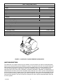
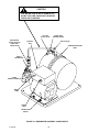
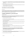
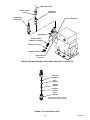
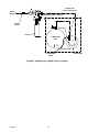
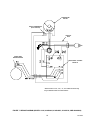
IMI CORNELIUS INC g One Cornelius Place g Anoka, MN 55303-6234 Telephone (800) 238-3600 Facsimile (612) 422-3246 LOW PROFILE LARGE RESERVE CARBONATOR Service Manual IMPORTANT: It is the responsibility of the Service Person to ensure that the water supply to the dispensing equipment is provided with protection against backflow by an air gap as defined in ANSI/ASME A112. 1.2-1979; or an approved vacuum breaker or other such method as proved effective by test. Water pipe connections and fixtures directly connected to a potable water supply shall be sized, installed, and maintained according to Federal, State, and Local laws. When installing in an area regulated by the City of Los Angeles Plumbing and/or Mechanical Codes, a City of Los Angeles approved reduced pressure principle backflow preventer shall be installed on each potable water supply to each carbonator. Part No. 319798006 April 4, 1985 Revised: March 11, 1997 Control Code B THIS MANUAL IS NOW “OBSOLETE”. SERVICE INFORMATION WAS INCORPORATED INTO THE INSTALLATION/ SERVICE MANUAL 319798001. LARRY POTTS WAS INFORMED. 5/17/00 THIS DOCUMENT CONTAINS IMPORTANT INFORMATION This Manual must be read and understood before installing or operating this equipment IMI CORNELIUS INC; 1998 PRINTED IN U.S.A TABLE OF CONTENTS Page SAFETY INFORMATION . . . . . . . . . . . . . . . . . . . . . . . . . . . . . . . . . . . . . . . . . . . . . . . . . . . . 1 RECOGNIZE SAFETY INFORMATION . . . . . . . . . . . . . . . . . . . . . . . . . . . . . . . 1 UNDERSTAND SIGNAL WORDS . . . . . . . . . . . . . . . . . . . . . . . . . . . . . . . . . . . . 1 FOLLOW SAFETY INSTRUCTIONS . . . . . . . . . . . . . . . . . . . . . . . . . . . . . . . . . 1 CO2 (CARBON DIOXIDE) WARNING . . . . . . . . . . . . . . . . . . . . . . . . . . . . . . . . 1 SHIPPING, STORING, OR RELOCATING UNIT . . . . . . . . . . . . . . . . . . . . . . . 1 GENERAL INFORMATION . . . . . . . . . . . . . . . . . . . . . . . . . . . . . . . . . . . . . . . . . . . . . . . . . . 3 TO THE USER OF THIS MANUAL . . . . . . . . . . . . . . . . . . . . . . . . . . . . . . . . . . . . . . . 3 CLAIMS INSTRUCTIONS . . . . . . . . . . . . . . . . . . . . . . . . . . . . . . . . . . . . . . . . . . . . . . 3 WARRANTY REFERENCE INFORMATION . . . . . . . . . . . . . . . . . . . . . . . . . . . . . . . 3 DESIGN DATA . . . . . . . . . . . . . . . . . . . . . . . . . . . . . . . . . . . . . . . . . . . . . . . . . . . . . . . . 3 UNIT DESCRIPTION . . . . . . . . . . . . . . . . . . . . . . . . . . . . . . . . . . . . . . . . . . . . . . . . . . . 4 THEORY OF OPERATION . . . . . . . . . . . . . . . . . . . . . . . . . . . . . . . . . . . . . . . . . . . . . . 5 SERVICE AND MAINTENANCE . . . . . . . . . . . . . . . . . . . . . . . . . . . . . . . . . . . . . . . . . . . . . 7 PREPARING UNIT FOR SHIPPING, STORING, OR RELOCATING . . . . . . . . . . 7 LUBRICATION . . . . . . . . . . . . . . . . . . . . . . . . . . . . . . . . . . . . . . . . . . . . . . . . . . . . . . . . 8 ADJUSTING CARBONATOR CO2 REGULATOR . . . . . . . . . . . . . . . . . . . . . . . . . . 8 WATER PUMP YEARLY MAINTENANCE (OR AFTER WATER SYSTEM DISRUPTIONS) . . . . . . . . . . . . . . . . . . . . . . . . . . . . . . . . . . . . . . . . . . . . . . . . . . . . . . . 8 SERVICING WATER PUMP WATER INLET STRAINER SCREEN . . . . . . . 8 SERVICING LIQUID DUAL CHECK VALVE . . . . . . . . . . . . . . . . . . . . . . . . . . . 10 THE VENTED DUAL CHECK VALVE ASSEMBLY . . . . . . . . . . . . . . . . . . . . . 11 CLEANING CARBONATOR CO2 GAS CHECK VALVE . . . . . . . . . . . . . . . . . . . . . 11 REPAIR AND REPLACEMENT . . . . . . . . . . . . . . . . . . . . . . . . . . . . . . . . . . . . . . . . . . 13 WATER PUMP . . . . . . . . . . . . . . . . . . . . . . . . . . . . . . . . . . . . . . . . . . . . . . . . . . . . 13 WATER PUMP MOTOR . . . . . . . . . . . . . . . . . . . . . . . . . . . . . . . . . . . . . . . . . . . . 14 CARBONATOR TANK LIQUID LEVEL CONTROL MODULE . . . . . . . . . . . . 15 SAFETY THERMOSTAT . . . . . . . . . . . . . . . . . . . . . . . . . . . . . . . . . . . . . . . . . . . . 15 VENTED DUAL CHECK VALVE . . . . . . . . . . . . . . . . . . . . . . . . . . . . . . . . . . . . . 16 TROUBLESHOOTING . . . . . . . . . . . . . . . . . . . . . . . . . . . . . . . . . . . . . . . . . . . . . . . . . . . . . . 21 CARBONATOR PUMP MOTOR WILL NOT OPERATE. . . . . . . . . . . . . . . . . . . . . . 21 CARBONATOR PUMP MOTOR WILL NOT SHUT OFF. . . . . . . . . . . . . . . . . . . . . 21 ERRATIC CYCLING OF CARBONATOR. . . . . . . . . . . . . . . . . . . . . . . . . . . . . . . . . . 21 CARBONATOR PUMP CAPACITY TOO LOW. . . . . . . . . . . . . . . . . . . . . . . . . . . . . . 22 CARBONATOR PUMP MOTOR OPERATES BUT CARBONATOR PUMP DOES NOT PUMP. . . . . . . . . . . . . . . . . . . . . . . . . . . . . . . . . . . . . . . . . . . . . . . . . . . . . . . . . . . . 22 WARRANTY . . . . . . . . . . . . . . . . . . . . . . . . . . . . . . . . . . . . . . . . . . . . . . . . . . . . . . . . . . . . . . 23 LIST OF FIGURES FIGURE 1. LOW PROFILE LARGE RESERVE CARBONATOR . . . . . . . . . . . . . . 4 FIGURE 2. CARBONATOR ASSEMBLY COMPONENTS . . . . . . . . . . . . . . . . . . . 9 FIGURE 3. LIQUID CHECK VALVE ASSEMBLY . . . . . . . . . . . . . . . . . . . . . . . . . . . 10 FIGURE 4. WATER STRAINER SCREEN AND LIQUID DUAL CHECK VALVE . 12 FIGURE 5. CO2 GAS CHECK VALVE . . . . . . . . . . . . . . . . . . . . . . . . . . . . . . . . . . . . 12 i 319798006 TABLE OF CONTENTS (cont’d) Page LIST OF FIGURES (CONT’D) FIGURE 6. VENTED DUAL CHECK VALVE LOCATION . . . . . . . . . . . . . . . . . . . . 17 FIGURE 7. WIRING DIAGRAM (MODELS 1624, 416424000, 41642400U, 411624102, AND 496424000) . . . . . . . . . . . . . . . . . . . . . . . . . . . . . . . . . . . . . . . . . . . . 18 FIGURE 8. WIRING DIAGRAM (MODEL NO. 8984, 49642400U, AND 496424040) . . . . . . . . . . . . . . . . . . . . . . . . . . . . . . . . . . . . . . . . . . . . . . . . . . . . . . . . . . . 19 LIST OF TABLES TABLE 1. DESIGN DATA . . . . . . . . . . . . . . . . . . . . . . . . . . . . . . . . . . . . . . . . . . . . . . . 319798006 ii 3 SAFETY INFORMATION Recognize Safety Information This is the safety-alert symbol. When you see this symbol on our machine or in this manual, be alert to the possibility of personal injury. Follow recommended precautions and safe operating practices. Understand Signal Words A signal word - DANGER, WARNING, OR CAUTION is used with the safety-alert symbol. DANGER identifies the most serious hazards. Safety signs with signal word DANGER or WARNING are typically near specific hazards. General precautions are listed on CAUTION safety signs. CAUTION also calls attention to safety messages in this manual. DANGER WARNING CAUTION Follow Safety Instructions Carefully read all safety messages in this manual and on your machine safety signs. Keep safety signs in good condition. Replace missing or damaged safety signs. Learn how to operate the machine and how to use the controls properly. Do not let anyone operate the machine without instructions. Keep your machine in proper working condition. Unauthorized modifications to the machine may impair function and/or safety and affect the machine life. CO2 (Carbon Dioxide) Warning CO2 Displaces Oxygen. Strict Attention must be observed in the prevention of CO2 (carbon dioxide) gas leaks in the entire CO2 and soft drink system. If a CO2 gas leak is suspected, particularly in a small area, immediately ventilate the contaminated area before attempting to repair the leak. Personnel exposed to high concentration of CO2 gas will experience tremors which are followed rapidly by loss of consciousness and suffocation. Shipping, Storing, Or Relocating Unit CAUTION: All water must be purged from the Unit if exposed to freezing temperature. A freezing ambient temperature will cause residual water remaining inside the Unit to freeze resulting in damage to internal components of the Unit. 1 319798006 THIS PAGE LEFT BLANK INTENTIONALLY 319798006 2 GENERAL INFORMATION TO THE USER OF THIS MANUAL CAUTION: This Unit must not be installed in an unsheltered outdoor location where it will be exposed to the elements. This Manual is a guide for performing service and maintenance procedures on this equipment. Refer to Table of Contents for page location of detailed service and maintenance procedures. A Parts Manual (P/N 319798003) for this equipment is available upon request. This Unit must be serviced by a qualified Service Person. This Unit contains no user serviceable parts. CLAIMS INSTRUCTIONS Claims: In the event of shortage, notify the carrier as well as IMI Cornelius immediately. In the event of damage, notify the carrier. IMI Cornelius is not responsible for damage occurring in transit, but will gladly render assistance necessary to pursue your claim. Merchandise must be inspected for concealed damage within 15 days of receipt. WARRANTY REFERENCE INFORMATION Warranty Registration Date (to be filled out by customer) Unit Part Number: Serial Number: Install Date: Local Authorized Service Center: DESIGN DATA Table 1. Design Data Unit Part Numbers: 115 VAC, 50/60 HZ Unit (Liquid dual check valve) 115 VAC, 50/60 HZ Unit (Liquid dual check valve) 115 VAC, 50/60 HZ Unit (Vented dual check valve) 115 VAC, 50/60 HZ Unit (Vented dual check valve) 220 VAC, 50 HZ/230 VAC, 60 Hz Unit (Liquid dual check valve) 230 VAC, 50 HZ Unit (Liquid dual check valve) 230 VAC, 50 HZ Unit (Vented dual check valve) 230 VAC, 50 HZ Unit (Liquid dual check valve) 3 41642400U 416424000 1624 411624102 496424000 496424040 8984 49642400U 319798006 Table 1. Design Data (cont’d) Overall Dimensions: Width Height Depth 15-1/2 inches 13 inches 11-1/4 inches Weight: Dry Shipping 27 pounds 32 pounds Ambient Operating Temperature 40° F to 100° F Maximum CO2 Operating Pressure 125-PSI Electrical Requirements: 115 VAC, 50/60 HZ Unit: Current Draw Operating Voltage 230 VAC, 50 HZ Unit Current Draw Operating Voltage 8.1/6.5 Amps 115VAC, 50/60 Hz 3.3 Amps 230VAC, 50 Hz FIGURE 1. LOW PROFILE LARGE RESERVE CARBONATOR UNIT DESCRIPTION The carbonator is a compact Unit that may be installed in a remote location from where its carbonated water outlet is to be connected to a post-mix dispenser or system. The purpose of the Unit is to mix plain water and carbon dioxide (CO2) gas which results in and provides carbonated water for a post-mix dispenser or system. The Unit consists basically of a water pump, motor, and a carbonator water tank. The water pump has a liquid dual check valve (Unit Part No. 41642400U, 416424000, 49642400U, 496424000, and 496424040) or a Vented Dual-Check Valve (Unit Part No.1624, 8984, and 411624102) on its outlet to prevent carbonated water from back flowing into the city water system. The Vented-Dual Check Valve vents water and possibly CO2 gas out of a vent port on failure of the Primary Check Valves. Should such venting occur, the Vented-Dual Check Valve should be replaced. The Unit CO2 inlet has a single check valve to prevent carbonated water back flow into CO2 regulator. 319798006 4 THEORY OF OPERATION A CO2 cylinder delivers CO2 (carbon dioxide) gas through an adjustable CO2 regulator to the carbonator water tank. At the same time, plain water is pumped into the carbonator water tank by the water pump and is carbonated by CO2 gas also entering the tank. When carbonator water tank carbonated water level has been satisfied, liquid level sensing device inside the tank signals the liquid level control module which in turn shuts off the water pump motor and the water pump. As carbonated water is drawn and carbonated water level in the tank drops to a certain level, the liquid level sensing device inside the water tank signals the liquid level control module that carbonated water must be replenished which in turn starts the water pump motor and the pump. 5 319798006 This manual is now obsolete. Service Information from this manual has been incorporated into the Installation Manual which is now an Installation/Service Manual 319798001. (5/10/00) THIS MANUAL IS NOW “OBSOLETE”. SERVICE INFORMATION WAS INCORPORATED INTO THE INSTALLATION/ SERVICE MANUAL 319798001. LARRY POTTS WAS INFORMED. 5/17/00 6 THIS PAGE LEFT BLANK INTENTIONALLY 7 319798006 SERVICE AND MAINTENANCE This section describes service and maintenance procedures to be performed on the Unit. IMPORTANT: Only qualified personnel should service internal components or electrical wiring. WARNING: Disconnect electrical power to the carbonator to prevent personnel injury before attempting any internal maintenance. CAUTION: Never operate the carbonator with the water inlet supply line shutoff valve closed. ‘‘Dry running’’ the water pump will burn out the pump. A pump damaged in this manner is not covered by warranty. WARNING: Strict attention must be observed in the prevention of CO2 (carbon dioxide) gas leaks in the entire CO2 soft drink system. If a CO2 gas leak is suspected, particularly in a small area, immediately ventilate the contaminated area before attempting to repair the leak. Personnel exposed to high concentrations of CO2 gas will experience tremors which are followed rapidly by loss of consciousness and suffocation. CAUTION: To prevent a fire hazard, no object should be placed or stored on top of the Unit. PREPARING UNIT FOR SHIPPING, STORING, OR RELOCATING IMPORTANT: All water must be purged from the Unit if exposed to a freezing temperature. A freezing ambient will cause residual water inside the Unit to freeze resulting in damage to internal components. Damage of this type will void the warranty. Perform the following procedure to purge water from the Unit. 1. Disconnect electrical power from the Unit. 2. Close water inlet supply line shutoff valve. 3. Disconnect water inlet supply line from the Unit. 4. Dispense from one of the dispensing valves until all carbonated water has been dispensed from the carbonator water tank. 5. Shut off CO2 supply to the Unit, then disconnect CO2 inlet supply line. 6. Connect filtered dry compressed air (50-psi max) to the Unit water inlet. DO NOT USE CO2 GAS WHICH COULD CAUSE A HEALTH HAZARD. 7. Dispense from one of the dispensing valves until all residual water has been blown from the Unit and lines. 8. Disconnect filtered dry compressed air from the Unit water inlet. 9. Disconnect carbonated water outlet line from the Unit. 10. The Unit is now ready for shipping or relocating. 319798006 8 LUBRICATION The water pump motor bearings must be oiled periodically. Refer to oiling instructions on the motor. DO NOT OVER OIL. ADJUSTING CARBONATOR CO2 REGULATOR NOTE: To readjust the CO2 regulator to a lower setting, loosen the adjusting screw lock nut, then turn the screw to the left (counterclockwise) until the pressure gage reads 5-psi lower than the new setting will be. Turn the adjusting screw to the right (clockwise) until the gage registers new setting, then tighten the lock nut. Loosen the CO2 regulator adjusting screw lock nut. Turn the carbonator CO2 regulator adjusting screw to the right (clockwise) until the regulator gage reads nominal 80-psig, then tighten the lock nut. DO NOT EXCEED 125-PSIG. WATER PUMP YEARLY MAINTENANCE (OR AFTER WATER SYSTEM DISRUPTIONS) WARNING: The carbonator water pump water inlet strainer screen and the liquid dual check valve (Unit Model No. 416424000, 41642400U, 496424000, 49642400U and 496424040) must be inspected and serviced at least once a year under normal circumstances, and after any disruptions (plumbing work, earthquake, etc.) to the water supply system that might cause turbulent (erratic) flow of water through the system. If the system has a Vented Dual–Check Valve (Unit Model No. 1624, 8984, and 411624102), clean the carbonator water pump water inlet strainer screen and flush the system. A carbonator water pump with no screen or a defective screen in the strainer would allow foreign particles to foul the double-check valve. CO2 gas could then back flow into the water system and create a health hazard in the water system. SERVICING WATER PUMP WATER INLET STRAINER SCREEN (see Figure 4) 1. Disconnect electrical power from the Unit. 2. Close the Unit water inlet supply line shutoff valve. 3. Note pressure setting on the carbonator CO2 regulator. Loosen the lock nut and turn the CO2 regulator adjusting screw to the left (counterclockwise) until the regulator gage reads 0-psi. 4. Remove quick disconnect from outlet side of the soft drink tank. 5. Place container under the applicable dispensing valve of syrup system soft drink tank was disconnected from. Open dispensing the valve and dispense carbonated water until the carbonator tank CO2 pressure has been released. 6. Loosen the screen retainer, then pull the screen retainer and strainer screen from the water pump. 7. Pull strainer screen from the screen retainer. Clean any sediment from the screen retainer and the water pump screen retainer port. 8. Inspect the strainer screen for holes, restrictions, corrosion, and other damage. Discard damaged strainer screen. 9 319798006 CAUTION THIS WATER TUBE IS NOT A HANDLE LIFTING BY THIS TUBE CAN RESULT IN WATER LEAKS AND FLOODING. CO2 GAS CHECK VALVE VENTED DUAL CHECK VALVE OR LIQUID DUAL CHECK VALVE LIQUID LEVEL SENSING DEVICE RELIEF VALVE CONTROL BOX CARBONATOR WATER TANK SAFETY THERMOSTAT COVER RETAIING SCREW (2) WATER PUMP POWER CORD WATER PUMP MOTOR FIGURE 2. CARBONATOR ASSEMBLY COMPONENTS 319798006 10 9. Check O-Ring on the screen retainer. Replace worn or damaged O-Ring (P/N 315349000). NOTE: A strainer screen should always be used, otherwise particles could foul the liquid double check valve. 10. Install good or new strainer screen (P/N 315348000) in the screen retainer, then screw the retainer into the water pump and tighten securely. 11. Service liquid double check valve (refer to next paragraph, SERVICING LIQUID DUAL CHECK VALVE). SERVICING LIQUID DUAL CHECK VALVE (see Figure 2 and 4) 1. Service the water strainer screen as instructed in previous paragraph, SERVICING WATER PUMP STRAINER SCREEN before servicing the liquid dual check valve. 2. Disconnect the water tank inlet line from the water tank inlet and from the liquid dual check valve assembly outlet. Remove the check valve assembly from the water pump outlet port. 3. Disassemble each check valve as shown in Figure 3. 4. Wipe each part with clean lint-free cloth. Inspect each part, especially the ball for burrs, nicks, corrosion, deterioration, and other damage. Discard the ball seat and any damaged or suspicious parts and replace with new parts during reassemble. 5. Reassemble check valves as shown in Figure 3. ALWAYS INSTALL NEW BALL SEAT (O-RING) ITEM 2 AND FLAT WASHER (ITEM 1). 4 3 INDEX NO. PART NO. 1 *560000480 4 312419000 560000481 2 *560000432 1 NAME FLAT WASHER BALL SPRING 2 4 3 1 2 BALL SEAT (O-RING) * INSTALL NEW BALL SEAT (ITEM 2) AND FLAT WASHER (ITEM 1) AT EACH SERVICING NOTE: Make sure when assembling the check valves together, the FLAT WASHER (item 1) is in place inside female end of the check valve. FIGURE 3. LIQUID CHECK VALVE ASSEMBLY 6. Assemble the check valves together. DO NOT OVERTIGHTEN. 7. Install the liquid dual check valve assembly in the water pump outlet port. 8. Connect the water tank water inlet line between the water tank water inlet and the liquid dual check valve assembly outlet. DO NOT OVER TIGHTEN. 11 319798006 9. Turn the carbonator CO2 regulator adjusting screw to the right (clockwise) until the gage indicates pressure setting noted in step 3 of SERVICING WATER PUMP WATER STRAINER SCREEN. Tighten the adjusting screw lock nut. 10. Open the Unit water inlet supply line shutoff valve. 11. Connect electrical power to the Unit. The water pump will start and fill the carbonator water tank. Check for water leaks and tighten any loose connections. 12. Install quick disconnect on the soft drink tank outlet. THE VENTED DUAL CHECK VALVE ASSEMBLY (see Figure 4) A vented dual check valve assembly is installed in the carbonator between the water pump outlet and the water inlet to the carbonator water tank as shown in Figure 6. The vented dual check valve assembly vents carbonated water, and possibly CO2 gas out of a vent port upon failure of the primary check valves. Should such venting occur, the vented dual check valve assembly must be replaced. CLEANING CARBONATOR CO2 GAS CHECK VALVE (see Figures 2 and 5) The carbonator tank CO2 gas check valve must be inspected and serviced at least once a year under normal conditions and after any servicing or disruption of the CO2 system. ALWAYS REPLACE QUAD RING SEAL EACH TIME GAS CHECK VALVE IS SERVICED. Proceed as follows: 1. Disconnect electrical power from the Unit. 2. Note pressure setting on the carbonator CO2 regulator. 3. Loosen the CO2 regulator adjusting screw lock nut, then turn the screw to the left (counterclockwise) until the pressure gage reads 0-psi. 4. Relieve CO2 pressure from the carbonator water tank by pulling up on the pressure relief valve plastic cap on top of the water tank. 5. Disconnect the CO2 inlet line from the CO2 check valve inlet, then remove the CO2 check valve from the carbonator water tank. 6. Disassemble check valve as shown in Figure 5. 7. Wipe each part with a clean lint-free cloth. Inspect each part, especially the ball for burrs, nicks, corrosion, deterioration, and other damage. 8. Reassemble the check valve as shown in Figure 5. ALWAYS INSTALL NEW QUAD RING SEAL. 9. Install CO2 check valve in the carbonator water tank inlet fitting. MAKE SURE THE SHORTEST THREADED END OF THE CHECK VALVE IS SCREWED INTO THE CARBONATOR WATER TANK INLET FITTING FOR PROPER VALVE OPERATION. 10. Connect CO2 inlet line to CO2 check valve. 11. Turn the carbonator CO2 regulator adjusting screw to the right (clockwise) until the pressure gage registers pressure noted in step 2 preceding, then tighten the adjusting screw lock nut. 12. Connect electrical power to the carbonator. 319798006 12 WATER LINE TO TANK WHITE TAPERED GASKET LIQUID DUAL CHECK VALVE VENTED DUAL CHECK VALVE SAFETY THERMOSTAT WATER PUMP WATER STRAINER SCREEN (P/N 315348000) O-RING (P/N 315349000) SCREEN RETAINER PUMP-TO-MOTOR COUPLING FIGURE 4. WATER STRAINER SCREEN AND LIQUID DUAL CHECK VALVE QUAD RING 183294000 BALL 183296000 SPRING 183297000 RETAINER 183298000 BODY 183295100 *Quad ring seal must be replaced each time check valve is serviced. FIGURE 5. CO2 GAS CHECK VALVE 13 319798006 REPAIR AND REPLACEMENT WATER PUMP (see Figures 2 and 4) Removal. 1. Disconnect electrical power from the Unit. 2. Close the CO2 cylinder shutoff valve, then close the shutoff valve in the water inlet supply line. 3. Pull up on the carbonator water tank relief valve plastic cap to release CO2 pressure from the water tank. 4. Disconnect the water inlet supply line from the water pump water inlet fitting. Be careful not to lose the black tapered gasket inside the swivel nut. 5. Disconnect the water tank water inlet line from the water tank inlet fitting and the liquid dual check valve assembly outlet or the vented dual check valve assembly outlet. 6. Remove the liquid dual check valve assembly or the vented dual check valve assembly from the water pump outlet port. 7. Note position of the safety thermostat on the water pump outlet, then remove the thermostat from the pump. 8. Remove fitting from the water pump inlet port. 9. Loosen screw on the pump-to-motor coupling enough to remove the water pump from the motor. Installation. 1. Disassemble and clean the liquid dual check valve assembly as instructed in steps 3 through 6 of SERVICING LIQUID DUAL CHECK VALVE. 2. Install the new water pump by reversing the Removal procedure and use the following instructions. A. Make sure pipe thread sealing compound is used on the fittings threads when installing the liquid dual check valve assembly or the vented dual check valve assembly and fitting in the inlet and outlet ports of the new water pump. B. Make sure drive tang on the water pump and slot in the pump motor shaft are properly lubricated and aligned when installing the water pump on the motor. 3. Open the CO2 cylinder shutoff valve, then open the Unit water inlet supply line shutoff valve. 4. Connect electrical power to the Unit. 5. Dispense carbonated water from one of the dispensing valves to make the Unit cycle on. Check for water leaks and tighten or repair any loose connections. 319798006 14 WATER PUMP MOTOR (see Figures 2 and 4) Removal. 1. Disconnect electrical power from the Unit. 2. Loosen screw on the pump-to-motor coupling to disconnect the water pump from the motor, then remove pump from the motor. 3. Remove screws securing the control box cover, then remove the cover. 4. Disconnect the black and white pump motor electrical wires from the L1 and L2 terminals on the control module. 5. Tag the pump motor electrical wires for identification, then disconnect wires from the motor terminals. 6. Remove conduit fitting securing the control box to the pump motor, then remove the control box from the motor and lay off to one side. 7. Remove screw and clamp securing the water pump motor to the base, then remove old motor. Installation. 1. Install new pump motor by reversing the Removal procedure. 2. Make sure tang on the water pump and slot in the pump motor shaft are properly lubricated and aligned when installing the water pump on the motor. 3. Make sure all wiring is correct (see Figure 7). 4. Install the control box cover and secure with screws. 5. Connect electrical power to the Unit. CARBONATOR TANK LIQUID LEVEL SENSING DEVICE (see Figure 2) Removal. 1. Disconnect electrical power from the Unit. 2. Close the Unit water inlet supply line shutoff valve. 3. Note pressure setting on the carbonator CO2 regulator, then loosen the lock nut and turn the CO2 regulator adjusting screw to the left (counterclockwise) until the regulator gage reads 0-psi. 4. Remove quick disconnect from outlet side of the soft drink tank. 5. Place container under the applicable dispensing valve of the syrup system the soft drink tank was disconnected from. Open the dispensing valve and dispense carbonated water until the carbonator water tank CO2 pressure has been released. 6. Disconnect electrical polarized plug from the liquid level sensing device electrical connector. 7. Remove the threaded liquid level sensing device from the carbonator water tank. 15 319798006 Installation. 1. Install new liquid level sensing device in the carbonator water tank by reversing the Removal procedure. 2. Connect the electrical polarized plug to the new liquid level sensing device electrical connector. 3. Restore the carbonator CO2 regulator to the pressure noted in step 3 of Removal. 4. Open the Unit water inlet supply line shutoff valve. 5. Connect electrical power to the Unit. CARBONATOR TANK LIQUID LEVEL CONTROL MODULE (see Figure 2) Removal. 1. Disconnect electrical power from the Unit. 2. Remove screws securing the control box cover, then remove the cover. 3. Remove screws securing the liquid level control module inside the control box. 4. Label the electrical wires connected to the liquid level control module for identification, then disconnect wires from the module. Installation. 1. Install new liquid level control module by reversing the Removal procedure. 2. Make sure electrical wires are correctly connected to the control module (see Figure 7). 3. Install the control box cover and secure with screws. 4. Connect electrical power to the Unit. SAFETY THERMOSTAT (see Figure 2) Removal. 1. Disconnect electrical power from the Unit. 2. Remove screws securing the control box cover, then remove the cover. 3. Disconnect safety thermostat wires from the control module terminals. 4. Pull safety thermostat wires out of the control box. 5. Note position of the safety thermostat on the water pump outlet, then remove the thermostat. 319798006 16 Installation. 1. Install new safety thermostat by reversing the Removal procedure. 2. Make sure the safety thermostat electrical wires are properly connected (see Figure 7). 3. Install the control box cover and secure with screws. 4. Connect electrical power to the Unit. VENTED DUAL CHECK VALVE (see Figure 4) Removal. 1. Disconnect electrical power from the unit. 2. Close the CO2 cylinder shutoff valve then close shutoff valve in the water inlet supply line. 3. Pull up on the carbonator water tank relief valve plastic cap to release CO2 pressure from the tank. 4. Disconnect water tank inlet line from the vented dual check valve assembly. 5. Remove vent line from the vented dual check valve assembly. 6. Remove the vented dual check valve assembly from the water pump outlet port. Installation. 1. Install new vented dual check valve in the water pump outlet port. (be sure flow direction arrow points up). 2. Using tapered gasket connect water line from the water tank to the top of the vented dual check valve. Tighten fittings. 3. Attach vent line to the vented dual check valve. 4. Open CO2 cylinder shutoff valve, then open water inlet supply line shutoff valve. 5. Check carefully for leaks and repair if evident. 6. Connect electrical power to the Unit. 7. Allow the Unit to cycle several times while observing for correct operation. 17 319798006 VENTED DUAL CHECK VALVE ASS’Y WATER SOURCE CARBONATOR ASS’Y (PARTIAL) SHUTOFF VALVE VENT PORT FILTER CARBONATOR TANK VENT TUBE TO PERMANENT DRAIN FIGURE 6. VENTED DUAL CHECK VALVE LOCATION 319798006 18 WATER PUMP WATER PUMP MOTOR SAFETY THERMOSTAT (P/N 317989-000) G CONTROL BOX LIQUID LEVEL SENSING DEVICE *LIQUID LEVEL CONTROL MODULE * Actual location of “HI”, “LO”, “C”, and “LOAD” terminals may vary on different brands of control modules. FIGURE 7. WIRING DIAGRAM (MODELS 1624, 416424000, 41642400U, 411624102, AND 496424000) 19 319798000 WATER PUMP MOTOR SAFETY THERMOSTAT (P/N 317989-000) CONTROL BOX LIQUID LEVEL SENSING DEVICE *LIQUID LEVEL CONTROL MODULE * Actual location of “HI”, “LO”, “C”, and “LOAD” terminals may vary on different brands of control modules. FIGURE 8. WIRING DIAGRAM (MODEL NO. 8984, 49642400U, AND 496424040) 19 319798006 THIS PAGE LEFT BLANK INTENTIONALLY 319798006 20 TROUBLESHOOTING IMPORTANT: Only qualified personnel should service internal components or electrical wiring. WARNING: If repairs are to be made to a product system, remove quick disconnects from the applicable product tank, then relieve the system pressure before proceeding. If repairs are to be made to the CO2 system, stop dispensing, shut off the CO2 supply, then relieve the system pressure before proceeding. If repairs are to be made to the refrigeration system, make sure electrical power is disconnected from the unit. Trouble CARBONATOR PUMP MOTOR WILL NOT OPERATE. CARBONATOR PUMP MOTOR WILL NOT SHUT OFF. ERRATIC CYCLING OF CARBONATOR. Probable Cause Remedy A. Unit power cord unplugged or circuit breaker open in panel box. A. Plug in Unit power cord or reset circuit breaker. B. Inoperable pump motor. B. Replace pump motor as instructed. C. Overheated motor cut off by thermal overload protector. C. Check for proper line voltage. Check for restricted pump discharge. D. Inoperative liquid level control module. D. Replace liquid level control module as instructed. E. Liquid level sensing device inside carbonator tank inoperable. E. Replace sensing device as instructed. F. Loose electrical connection and/or open electrical circuit. F. Tighten connection and/or repair open circuit. Check line voltage. G. Carbonator pump binding (new or replacement pumps only). G. Remove carbonator pump from motor, rotate pump or motor shaft 180 degrees, then recouple pump to motor. H. Carbonator pump damaged. H. Replace carbonator pump as instructed. A. Liquid level sensing device inside carbonator tank inoperable. A. Replace sensing device as instructed. B. Loose electrical connection and/or open electrical circuit. B. Tighten connection and/or repair open circuit. C. Inoperable liquid level control module. C. Replace liquid level control module as instructed. D. Leak in carbonated water system. D. Repair carbonated water system. A. Liquid level sensing device inside carbonator tank inoperable. A. Replace sensing device as instructed. B. Liquid level control module inoperable. B. Replace liquid level control module as instructed. 21 319798006 Trouble CARBONATOR PUMP CAPACITY TOO LOW. CARBONATOR PUMP MOTOR OPERATES BUT CARBONATOR PUMP DOES NOT PUMP. 319798006 Probable Cause Remedy A. Pump inlet water strainer screen dirty. A. Clean or replace water strainer screen as instructed. B. Kinked plain water inlet supply line. B. Straighten plain water inlet supply line. C. Foreign object in pump bypass. C. Clean. (Note: Count number of turns bypass screw makes when removing and install same number of turns). D. Water pump worn out. D. Replace water pump as instructed. E. Water filter clogged. E. Replace water filter. A. Water pump inlet water strainer screen dirty. A. Clean or replace water strainer screen as instructed. B. Water supply too low or turned off. B. Inlet water supply must be a minimum of 100-gallons per hour with a maximum water pressure of 70-psi. C. Water filter clogged. C. Replace water filter. D. Inoperative water pump. D. Replace water pump as instructed. 22 WARRANTY IMI Cornelius Inc. warrants that all equipment and parts are free from defects in material and workmanship under normal use and service. For a copy of the warranty applicable to your Cornelius, Remcor or Wilshire product, in your country, please write, fax or telephone the IMI Cornelius office nearest you. Please provide the equipment model number, serial number and the date of purchase. IMI Cornelius Offices AUSTRALIA D P.O. 210, D RIVERWOOD, D NSW 2210, AUSTRALIA D (61) 2 533 3122 D FAX (61) 2 534 2166 AUSTRIA D AM LANGEN FELDE 32 D A-1222 D VIENNA, AUSTRIA D (43) 1 233 520 D FAX (43) 1-2335-2930 BELGIUM D BOSKAPELLEI 122 D B-2930 BRAASCHAAT, BELGIUM D (32) 3 664 0552 D FAX (32) 3 665 2307 BRAZIL D RUA ITAOCARA 97 D TOMAS COELHO D RIO DE JANEIRO, BRAZIL D (55) 21 591 7150 D FAX (55) 21 593 1829 ENGLAND D TYTHING ROAD ALCESTER D WARWICKSHIRE, B49 6 EU, ENGLAND D (44) 789 763 101 D FAX (44) 789 763 644 FRANCE D 71 ROUTE DE ST. DENIS D F-95170 DEUIL LA BARRE D PARIS, FRANCE D (33) 1 34 28 6200 D FAX (33) 1 34 28 6201 GERMANY D CARL LEVERKUS STRASSE 15 D D-4018 LANGENFELD, GERMANY D (49) 2173 7930 D FAX (49) 2173 77 438 GREECE D 488 MESSOGION AVENUE D AGIA PARASKEVI D 153 42 D ATHENS, GREECE D (30) 1 600 1073 D FAX (30) 1 601 2491 HONG KONG D 1104 TAIKOTSUI CENTRE D 11-15 KOK CHEUNG ST D TAIKOKTSUE, HONG KONG D (852) 789 9882 D FAX (852) 391 6222 ITALY D VIA PELLIZZARI 11 D 1-20059 D VIMARCATE, ITALY D (39) 39 608 0817 D FAX (39) 39 608 0814 NEW ZEALAND D 20 LANSFORD CRES. D P.O. BOX 19-044 AVONDALE D AUCKLAND 7, NEW ZEALAND D (64) 9 8200 357 D FAX (64) 9 8200 361 SINGAPORE D 16 TUAS STREET D SINGAPORE 2263 D (65) 862 5542 D FAX (65) 862 5604 SPAIN D POLIGONO INDUSTRAIL D RIERA DEL FONOLLAR D E-08830 SANT BOI DE LLOBREGAT D BARCELONA, SPAIN D (34) 3 640 2839 D FAX (34) 3 654 3379 USA D ONE CORNELIUS PLACE D ANOKA, MINNESOTA D (612) 421-6120 D FAX (612) 422-3255 LD004 4/21/98 23 319798006 IMI CORNELIUS INC. CORPORATE HEADQUARTERS: One Cornelius Place Anoka, Minnesota 55303-6234 (612) 421-6120 (800) 238-3600


![Service Manual VA13 Carbonator [ 002818 ]](http://vs1.manualzilla.com/store/data/006013608_1-0f8f87056a0ab013b1dd01dac3912d47-150x150.png)