1
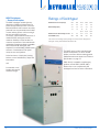
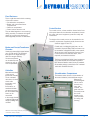
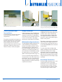
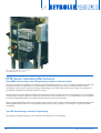
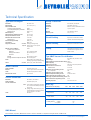
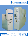
R E Y R O L L E PA C I F I C
Reliability and safety you can trust
LMVP 12 kV Indoor Switchgear
Wellington, New Zealand
P: + 64 4 568 3499 F: + 64 4 569 9688
Email: sales@reyrollepacif ic.co.nz
NZ
– Wellington
Australia – Brisbane
– Melbourne
Europe – Ireland
Asia
– Singapore
Africa
– Johannesburg
R E Y R O L L E PA C I F I C
LMVP Switchgear
– General Description
The LMVP switchgear enables the easy
distribution of Medium Voltage Electrical
Power through Networks to the Consumer.
Both the Networks and Consumer are safely
protected from any potentially harmful fault
currents utilising proven current sensing &
vacuum interrupter technology.
The simple, robust modular construction of
metalclad LMVP switchgear provides
maximum flexibility to meet variations in
customer requirements. New switchboards
and busbars systems are directly compatible
with all Reyrolle LM switchgear; with
emphasis on sound insulation, reliable service
and ease of maintenance. Each panel
comprises two main portions.
A fixed enclosure, or back part, housing
busbars, current transformers, relays and
instruments:
and
A removable circuitbreaker with integral
wheeled carriage.
2
Ratings of Switchgear
Rated Normal Current (Amps)
630
3.6
800
3.6
1250
3.6
2000
3.6
2500
3.6
Rated Voltage (kV)
7.2
7.2
7.2
7.2
7.2
12
12
12
12
12
Up to
Up to
Up to
31.5
584
31.5
914
31.5
914
Rated Short Circuit Breaking Current 25
Panel Width (mm)
584
25
584
The short-circuit breaking capacity ratings and normal current ratings of this
switchgear comply with Standards IEC 62271-100.
The LMVP range includes standard single
busbar feeder panels, as well as double
busbar, bus section and bus metering panels.
Outline dimensions are shown in the Technical
Specifications on page 13.
Other directly compatible complimentary
products include LMVC, LMLBS/LMFS.
Please refer to our complimentary LM
switchgear brochure for further information.
LMVP 12kV Indoor Switchgear
R E Y R O L L E PA C I F I C
Fixed Enclosure
This is a rigid sheet steel cubicle consisting
of four main sections:
• Circuit-breaker compartment
• Busbar and current transformer
compartments
• Cable box compartment
• Control section extension unit
They are bolted together in an accurate jig
during assembly, to maintain the highest
degree of accuracy with subsequent
interchangeability of similar circuit-breakers.
Control Section
The control section, a sheet metal box located at the front
of the panel above the circuit-breaker compartment, houses
the relays and control equipment, protection relays and
instruments.
The height of the control section can be extended to suit
customer requirements. Standard overall dimensions are
shown on pages 12 and 13.
Busbar and Current Transformer
Chamber
Contains the three-phase copper busbars
up to 3000A rating. Fully insulated
throughout their length with high
dielectric strength sleeving.
Current transformers
can be either Slip over
primary bar type or
resin encapsulated.
Control units, including the gear plate, can be
removed if required. Relays and instruments can
be mounted on a hinged door which, when opened,
allows access to the connections from the front.
Control switches and indicator lamps, when
required, are located on this door.
The fuses, terminals and other control equipment
are located behind the removable hinged door.
HRC fuses are fitted to control circuits as standard.
All secondary wiring is carried out in PVC insulated
cable with numbered ferrules.
Cable Box
Mounted at the back
of the currenttransformer chamber.
The air insulated
cable boxes for heat
shrink cable
termination, and
proprietary
terminations, as
standard. Modular
construction means
the air insulated cable
boxes can be
assembled
to form single, double
or triple arrangements
simply by adding extra
modules.
Circuit-breaker Compartment
The bottom section houses a circuit-breaker of
the vertical isolation, horizontal draw-out type.
Mounted on
substantial guide
rails to ensure
smooth, easy
entry and
removal. The
guide rails also
accurately locate
the circuitbreaker in the
correct position
for raising and
lowering.
LMVP Panel without voltage transformer, showing the
circuit-breaker partially withdrawn.
LMVP 12kV Indoor Switchgear
3
R E Y R O L L E PA C I F I C
Mk 1 Busbar chamber with interconnecting
Mk II busbar chamber
busbars and associated busbar shrouds in position.
Busbar connected VT risers can also be seen.
Busbar Chamber
The busbar chamber contains
three-phase copper busbars of
800A, 1250A, 1600A, 2000A,
2500A or 3000A rating, fully
insulated throughout their
length with high dielectric
strength sleeving. Direct panel
to panel busbar connections
are made without the use of
interconnecting links, the joints
being shrouded.
The busbar and feeder orifice
insulators, which also
incorporate the vertical
connectors, are moulded in
silica-filled epoxy resin which
combines high mechanical
strength with excellent
insulating properties. The
connectors terminate in silver
plated plug contacts which
engage with the self-aligning
sockets on the circuit-breaker.
4
Current transformer chamber top view
Interior view of control section
Current Transformer Chamber
Internal busbar end covers are
fitted, which enable extension
panels to be moved into their
final position, fixed, cabled up
and made ready before the
busbars on the existing gear
need to be made dead for the
connection of the extension set
of busbars.
This chamber houses current
transformers which may be low
voltage insulated mounted on
an insulated primary bar, or
silica-filled epoxy resin
insulated, and either bar or
wound primary type depending
on the ratios and outputs
required.
The current transformers have
the specified output and
accuracy under rated load
conditions, but are also capable
of withstanding, for a specified
time, the effects of the shortcircuit fault current within the
breaking capacity rating of the
switchgear.
This feature is important for
achieving a minimum of outage
time.
Current transformers comply
with IEC 60044-1 and AS
60044-1. One side of the
primary connection is solidly
connected to the vertical
connectors, with silver plated
contacts moulded into orifice
insulators as described in the
busbar chamber section. The
joints are shrouded. These plug
into the second set of sockets
on the circuit-breaker.
The minimum ratios available
are largely dependent upon
such factors as the short-circuit
fault current, the type and timesetting of the protection
specified, the total burden, and
the number of current
transformers to be
accommodated.
Primary bars without current
transformers fitted can also be
supplied.
LMVP 12kV Indoor Switchgear
R E Y R O L L E PA C I F I C
Selector gate mechanism for circuit-breaker
24 Way Plug & Socket for secondary isolation
Circuit-breaker compartment showing the orifice safety
shutters and associated operating mechanism.
Selector Gate
Secondary Connections
Selection of the circuit-breaker carriage
position for “busbar-earth”, “service” or
“circuit-earth” is achieved by a simple
selector gate mechanism located on the
inside right hand wall of the circuit-breaker
compartment.
This selector is linked to a shutter
mechanism which uncovers only one of
the three holes to allow the circuit-breaker
locating bolt to engage in the selected
position. Positions on the selector
mechanisms may be padlocked to ensure
that the correct key must be obtained
before the circuit-breaker position can be
changed.
Secondary connections between the circuitbreaker and the fixed portion are made by
means of a plug and socket which is
mounted on the right hand side of the
circuit-breaker. Up to 24 pins can be used
on this arrangement.
Safety interlocks ensure that the circuitbreaker cannot be raised into any operating
position until the secondary plug is engaged
in the socket. Electrical interlocks isolate
the trip circuit when the circuit-breaker is
raised into a busbar-earth or circuit-earth
position.
Alternatively, self-aligning secondary
isolating contacts can be fitted to the right
hand side of the circuit-breaker
compartment immediately below the
selector gate. Up to 24 contacts can be
fitted, although 12 or 18 are normally found
to be sufficient for most control circuits.
These contacts remain connected when
the circuit-breaker is locked in either the
raised or the lowered position. Since trip
circuit secondary isolating contacts are not
connected in the busbar-earth or circuitearth positions on the enclosure, the circuitbreaker is prevented from being
automatically tripped during closing into
or when closed in either earthing position.
(Note: padlocks are normally a user
responsibility, and are not supplied as
standard.)
Orifice Safety Shutters
Substantial safety shutters, actuated by
the raising or lowering of the circuit-breaker,
automatically expose or cover each threephase set of fixed isolating contacts. Each
shutter may be individually operated and
padlocked in the closed position.
Facilities are also provided to allow either
shutter to be fixed, but not padlocked, in
the open position for testing. Insertion of
the circuit-breaker into its enclosure cancels
this feature, and automatically restores the
normal operation of the shutters.
Busbar shutters are clearly labelled
BUSBARS, and are painted signal red
(BS381C colour 537). The circuit shutters
are labelled CIRCUIT, and painted lemon
(BS381C colour 255).
Circuit or Busbar Earthing
Busbar earthing is supplied as standard, with the option of Integral circuit and/or busbar earthing. Details should be specified when
ordering. These facilities are provided through the circuit-breaker without the use of loose attachments. The transfer-breaker method
is used whereby the circuit-breaker compartment, when fully raised, is connected to the main isolating plugs of the side to be earthed
and to the appropriate set of three fixed copper plug contacts solidly earthed by a common bonding strip. Closing the circuit-breaker
completes the operation.
For dependent power operation, secondary connections for the closing circuit are available in both earthing positions, but the circuitbreaker can only be tripped manually.
Integral circuit earthing switching of the cable can also be achieved with an earthing switch situated between the rear cable box
and circuit-breaker compartment. Its operation is managed by a rotating mechanical linkage assembly extending to the front of the
Circuit-Breaker Compartment for ease of operation. The integral Circuit method is rated to 20kA/3s.
LMVP 12kV Indoor Switchgear
5
R E Y R O L L E PA C I F I C
Control & Indication Cable Terminal Blocks
Circuit connected voltage transformer in the service position
Circuit connected voltage transformer in the isolated position
showing the secondary isolating contacts in the safety shutter
Control & Indication Cable
Terminal Blocks
Voltage-Transformers
Voltage transformers are in a three limb
configuration for directional protection. A
positively driven shutter automatically
covers the fixed isolating contacts when
the voltage transformer is isolated and
provision is made to allow padlocking the
shutter in this position.
Terminal blocks for external connections
are located at the top of the control
compartment.
The multicore terminal block location can
facilitate interpanel wiring. A small gland
plate is bolted to the top of the control
section extension unit in order to fix
multicore cables to the panel. At site this
gland plate is drilled to suit the size of
multicore cable (or cables) and glands.
Voltage transformers with silica-filled epoxy
resin encapsulated primary windings are
available as either fixed or withdrawable
units which can be connected to either the
circuit or to the busbars. The voltage
transformers comply with IEC, BS and AS.
Withdrawable voltage transformers
The withdrawable voltage transformers are
of the isolatable type and padlocking
facilities are provided in both the service
and isolated positions. Single phase or
three phase voltage transformers up to a
maximum of 3x1 phase assemblies can
be mounted onto a withdrawable carriage
for either busbar or circuit applications.
(Refer Technical Specifications, page 13.)
A circuit connected voltage transformer is
connected to the circuit side of the current
transformers so that it is included in the
zone of the protection equipment. Busbar
voltage transformer connectors are directly
coupled to the busbars.
6
This shutter is painted lemon and marked
CIRCUIT when the voltage transformer is
connected to the circuit side of the unit, it
is red marked BUSBARS when connected
to the busbars.
To protect the primary windings, high
voltage cartridge type fuses are fitted into
the primary bushings of the voltage
transformer. These can be removed only
when the transformer is isolated. Secondary
HRC fuses are mounted on the top of the
voltage transformer and are always readily
accessible.
Fixed Voltage Transformers
The fixed voltage transformers are in sets
of single phase units. Fixed voltage
transformers can be installed above the
current transformer chamber. Primary
fuses are fitted and are generally readily
accessible through a lockable shutter.
LMVP 12kV Indoor Switchgear
R E Y R O L L E PA C I F I C
Single cable box with circuit connected voltage transformer
housing fitted. (Covers removed to show internal details.)
Single Cable box without voltage transformer.
(Covers removed to show internal details.)
Cable Boxes
Cable Box type and Cable Options
Circuit cable boxes are mounted to the
back of the current-transformer
chamber. Air insulated cable boxes for
heat shrink cable termination, as used
with proprietary terminations, are
standard.
Modular construction means the air
insulated cable boxes can be
assembled to form single, double or
triple arrangements simply by adding
extra modules.
All cable boxes can be supplied with
gland arrangements to take cables of
various types and sizes for bottom, top
or angled entry.
Rated Normal Current (Amps)
Single box
Double box
Triple box
Single top entry cable box
630, 800, 1250
1x3 core up to 400mm2
or
3x1 core up to 630mm2
2x3 core up to 400mm2
or
6x1 core up to 630mm2
3x3 core up to 400mm2
or
12x1 core up to 630mm2
2000, 2500
6x1 core up to 630mm2
Up to 3x3 core up to 400mm2
or
Up to 12x1 core up to 630mm2
Note 1: Busbar end cable boxes, and 12x1 core cable boxes are available.
Note 2: Armoured cables can be accommodated up to:
1000mm2 for single core cable and 240mm2 for 3 core cable.
Maximum size of paper or plastic
insulated cables (vertically downwards
or vertically upwards) for air insulated
boxes with heat shrink terminations
are as follows:
LMVP 12kV Indoor Switchgear
7
R E Y R O L L E PA C I F I C
630/800 Amp LMVP vacuum circuit-breaker and integral
carriage
1250 Amp LMVP vacuum circuit-breaker and integral carriage
2000/2500 Amp LMVP vacuum circuit-breaker and integral
carriage
The LMVP vacuum circuit-breaker is
interchangeable with the Reyrolle LMT oil
circuit-breaker.
The interrupters have a typical life
expectancy of 10,000 mechanical
operations, 10,000 load current operations,
and between 30 to 100 fully rated shortcircuit operations.
LMVP Vacuum Circuit-Breaker
The circuit-breaker is mounted on a steel
carriage, having four flanged wheels to
facilitate location within the enclosure. A
central screw mechanism operated by a
removable handle is provided for raising
and lowering the circuit-breaker.
The RPM-series LMVP circuit-breaker has
3 separate dough moulded resin housings
containing the three vacuum interrupters
which are air insulated and separated by
perspex phase barriers. Primary through
bushings are also incorporated in the
housing and at their upper end
accommodate self-aligning multi-finger
isolating contacts. Guide pins are fitted to
the top plate to ensure correct location of
the circuit-breaker, and a copper contact
provides positive earthing of the unit.
8
The housing has moulded inserts which
provide accurate and simple location of
components. The main operating shaft is
coupled to the moving contacts of the
interrupters through a drive insulator.
Current transfer is through multi-laminated
sliding contacts and the added contact
load in the closed position is provided by
disc springs.
Copper-chrome contact material is used
in the interrupters to minimise contact
erosion. The added contact load spring
assembly gives indication that the erosion
limit has been reached.
Should interrupter replacement be required,
this and resetting are achieved without the
need for special tools.
There are three models of circuit-breaker
available, having ratings of 630/800 Amp,
1250 Amp and 2000/2500 Amp. The first
model is rated 630 Amp in a 630 Amp
enclosure, and 800 Amp in a 1250 Amp
enclosure. The 2000/2500 Amp model
has paralleled primary through bushings
and a single interrupter per phase.
LMVP 12kV Indoor Switchgear
R E Y R O L L E PA C I F I C
LMVP circuit-breaker top plate assembly 630, 800 or 1250A
VCB
Locating bolt and isolating mechanism
Handle for raising and lowering the circuit-breaker
Interlocks
Clearly labelled mechanical interlocks are
provided to prevent:
(a)A closed circuit-breaker from being
withdrawn from or inserted into the
isolating contacts.
(b)Tripping by attempted isolation since
access to the raising and lowering
mechanism is automatically prevented
when the circuit-breaker is closed.
(c)The closing of the circuit-breaker, except
when correctly located in the service,
earth, or isolated position or alternatively
when the circuit-breaker is withdrawn
from the enclosure.
(d)A circuit-breaker from being withdrawn
or replaced except when it is isolated
and in the appropriate location for
withdrawal or replacement.
(e)A circuit-breaker being closed in the
service position when the secondary
circuits between the fixed and moving
portions are not completed.
Interlocks (a), (b) and (c) are hand
controlled by a lever at the front of the
circuit-breaker, with positions labelled
Isolating Mechanism “free” or “locked”,
and Locating Bolt “free” or “locked”. This
locating bolt mechanism cannot be raised
except when the secondary circuits are
complete.
LMVP 12kV Indoor Switchgear
ISOLATING
CONTACTS
CIRCUIT BREAKER
GUIDE PINS
EPOXY RESIN
HOUSING
FIXED CONTACTBLOCK
VACUUM
INTERRUPTER
DOUGH
MOULDING
HOUSING
MOVING
SLIDING
CONTACT
CONNECTOR
BOTTOM
COVER
MECHANISM
OPERATING SHAFT
BUFFER
ASSEMBLY
MAIN OPERATING SHAFT
Cross section of a 1250A RPM Series vacuum circuit-breaker
9
R E Y R O L L E PA C I F I C
Motor charged spring mechanism – cover removed.
(Type QMRO, RPM series circuit-breaker.)
RPM Series Operating Mechanisms
Type QMRO: Stored energy, motor charged spring, manual or electrical release
The closing spring of this mechanism is charged by a small geared motor, either a.c. or d.c. To facilitate immediate reclosure after
tripping, the spring is recharged when the circuit-breaker is closed. Recharging of the spring is normally automatic with this
arrangement, but provision is made for emergency hand charging in the event of failure of the motor supply. The mechanism is
provided with mechanical and electrical releases for closing.
All mechanisms are trip free. With all mechanisms the opening springs are charged during the closing operations. The circuit-breaker
is opened with a mechanical actuator or electrically with a trip coil. Current transformer, a.c. or d.c. operated trip coils are available
as required. Padlocking facilities are provided to prevent manual trip and close operations.
Rotary spring loaded auxiliary switches are positively driven in both directions and are readily accessible to facilitate inspection and
cleaning. Additional limit switches can be provided to indicate closing spring “charged” or “discharged” on type QM or QMRO
mechanisms.
Type QM: Stored energy, manually charged spring
Type QM type operating mechanism is also available in the RPM Series of circuit-breaker.
10
LMVP 12kV Indoor Switchgear
R E Y R O L L E PA C I F I C
Hand charged spring mechanism – cover removed.
(Type QM, X Series circuit-breaker.)
Solenoid closing mechanism – cover removed.
(Type MO, X Series circuit-breaker.)
X Series Operating Mechanisms
Type QM: Stored energy, manually charged spring,
manual or electrical release
Type MO: Dependent power operation, solenoid
closing
The closing spring is charged by hand with a single upward stroke
of the operating handle, closing and tripping being effected by
means of a mechanical actuator. The spring can be recharged
with the circuit-breaker closed to permit an immediate reclosure
after any subsequent tripping. An electrical release can also be
provided.
The circuit-breaker is closed by a d.c. solenoid. Current for the
solenoid is usually supplied from a battery or a metal rectifier.
A silicon rectifier can be provided in the panel.
All RPM & X Series mechanisms are trip free. The opening spring is charged during the closing operations. The circuit-breaker is
opened with a mechanical actuator or electrically with a trip coil. Current transformer, a.c. or d.c. operated trip coils are available
as required. Padlocking facilities are provided to prevent manual trip and close operations.
Rotary spring loaded auxiliary switches are positively driven in both directions and are readily accessible to facilitate inspection and
cleaning.
LMVP 12kV Indoor Switchgear
11
R E Y R O L L E PA C I F I C
V
V
T
T
#
#
B*
C
C
A
A
G
E
F
B*
D
F
D
G
E
F
F
H
K
H
J
L
M
K
M
N
J
L
N
P
P
Q
P
Q
R
S
R
S
630-1250 Amp Panel
2000 Amp Panel
Cross-sectional View LMT/LMVP Switchgear
630-1250 AMP PANEL
A
B
Voltage transformer orifice housing
Voltage transformer.
Withdrawable type
* Also available with fixed type single
phase voltage transformers (1, 2 or
3).
# Also available as busbar connected
voltage transformer.
C Voltage transformer HV fuses
D Current transformer chamber (LV
insulated for bar primary and epoxy
resin encapsulated for wound primary
CTs)
E
Busbar Chamber
F
Connection shrouds
G Control Section
H Gear plate
J
Control gear mounted on control
section door
K Circuit earthing contacts
12
L
M
N
P
Q
R
S
T
V
Busbar earthing contacts
Orifice shutters
Selector gate mechanism controlling
circuit-breaker position
Circuit cable box, air insulated
Circuit-breaker
Circuit-breaker operating mechanism
Circuit-breaker carriage
Multicore terminal block
Multicore cable gland plate
2000 AMP PANEL
A
B
Voltage transformer housing
Voltage transformer.
Fixed type 1, 2 or 3 x single phase.
* Also available with withdrawable 3
phase voltage transformer, or 3 single
phase assembly. Refer to
630/1250A panel drawing.
# Also available as busbar connected
voltage transformer.
C
D
E
F
G
H
J
K
L
M
N
P
Q
R
S
T
V
Voltage transformer HV fuses
Current transformer chamber
Busbar Chamber
Connection shrouds
Control Section
Gear plate
Control gear mounted on control
section door
Circuit earthing contacts
Busbar earthing contacts
Orifice shutters
Selector gate mechanism controlling
circuit-breaker position
Circuit cable box, air insulated
Circuit-breaker
Circuit-breaker operating mechanism
Circuit-breaker carriage
Multicore terminal block
Multicore cable gland plate
LMVP 12kV Indoor Switchgear
R E Y R O L L E PA C I F I C
201 403
NOTE 3
533
734
N
O
T
E
N
O
T
E
1
1
152
NOTE 2
403
533
734
NOTE 3
Single Busbar
Double Cable Box
152
NOTE 2
Single Busbar
Single Cable Box
N
O
T
E
1
301
308
1268
152
NOTE 3
Double Busbar
Single Cable Box
NOTE 2
23
23
538
584
868
914
23
For special configurations of panels, refer to Reyrolle Pacific
Overall Dimensions
Widths shown apply to both single and double busbar panels.
Note 1:
2,100mm small height control section
2,400mm medium height control section
LMVP 12kV Indoor Switchgear
Note 2:
Distance required for circuit-breaker
removal:
700mm for 630-1250 Amp panels
1,200mm for 2000-2500 Amp panels
Note 3:
Distance required for access depends on
cabling requirements.
13
R E Y R O L L E PA C I F I C
Technical Specification
Voltage Transformer
Type LMVP Switchgear
Standards
Rated voltage
Rated insulation level:
Lightning impulse withstand
1 minute power-frequency withstand
Additional tests
Rated frequency
Rated short-time withstand current
Rated peak withstand current
Rated duration of short-circuit
Additional test
Internal fault (type tested)
Construction
Degree of protection
Standard
Optional
Normal service conditions
Ambient air temperatures:
Maximum
Average over 24 hours
Minimum
Altitude
Average relative humidity over 24 hours
Finish
Colour
IEC 62271-100
up to 12kV (r.m.s.)
95kVp
28kV (r.m.s.)
42kV (r.m.s.)
50Hz
up to 31.5kA
up to 79 kAp
3 seconds
4 seconds
25kA/0.1 sec
Metal clad
IP3X (approaching IP4X)
IP4X or higher to suit specific
requirements
Indoor
40 C (without derating)
o
Not exceeding 35 C
o
-5 C
Not exceeding 1,000m
Not exceeding 95%
Epoxy powder paint coating after
derusting, degreasing and phosphating
Standard Pipeline grey shade AS2700-N43
Silica-filled epoxy resin
Tinned copper. Heat shrink insulated.
Shrouded. Epoxy filled or unfilled
Up to 3000A
Current Transformer
Standards
Orifice insulators
Current transformers
Joints
IEC 60044-2, AS 60044-2
Silica-filled epoxy resin
Busbar or circuit; withdrawable or fixed
Up to 3x1 phase
Burdens
Accuracy class
up to 200VA per phase
0.2, 0.5 or 1.0
Circuit Earthing
By transfer circuit-breaker method
Optional interlocked earthing switch
Busbar Earthing
By transfer circuit-breaker method
Testing
High voltage test bushings can be
inserted into de-energised circuit or
busbar orifices
o
Busbar Chamber
Orifice insulators
Busbars
Joints
Rated normal current
Standards
Insulation
Connected
Types
IEC 60044-1, AS 60044-1
Silica-filled epoxy resin
Either a) Low voltage insulated type mounted
on a screened silica-filled epoxy resign
primary bar.
Or b) High voltage silica-filled epoxy resin
encapsulated type including multi-turn
primary designs for low ratios
Shrouded
Type LMVP Vacuum Circuit-Breaker
Standards
IEC 62271-100, AS 2006 - 1980
Rated voltage
12kV
Rated lightening impulse withstand voltage 95kVp
Rated frequency
50/60Hz
Rated normal current
630/800, 1250, 2000/2500A
Rated duration of short-circuit
3 seconds
Additional test
4 seconds
Rated short-circuit breaking current
25, 31.5kA
d.c. component
34%
Rated short-circuit making current
79kAp
Rated out-of-phase breaking current
6.25kA at 13.9kV
Rated cable charging breaking current
25A
Rated single capacitor bank breaking current 400A
Rated transformer magnetising current
6.3A
Operating sequence
O-0.3s-CO-15sec-CO
Mass (kg)
Rated normal current (Amp)
630
800 1250
Circuit-breaker on carriage
200
200
Enclosure complete with circuit-breaker
– Single busbar
520
Enclosure complete with circuit-breaker
– Double busbar
700
Extra for voltage transformer
including housing
3 phase
3 x 1 phase
2000
2500
230
315
315
550
580
930
940
730
760
1450
1460
160
90
These masses are approximate as current transformers and relays can vary as much as 250kg.
IOMS Manual
The Installation, Operation, Maintenance Service manual is available on request from Reyrolle Pacific in PDF format.
14
LMVP 12kV Indoor Switchgear
R E Y R O L L E PA C I F I C
NOTES
LMVP 12kV Indoor Switchgear
15
R E Y R O L L E PA C I F I C
Offices
New Zealand
LMVP Switchboard Installation
Reyrolle Pacific
Switchgear Ltd
7-17 Bouverie Street
Petone
Private Bag 39811
Wellington Mail Centre
New Zealand
Tel: + 64 4 568 3499
Fax: + 64 4 569 9688
[email protected]
www.reyrollepacific.co.nz
Australia
Melbourne
Reyrolle Pacific
Switchgear Pty Ltd
Office 8 – 11,
2187 Princes Highway
Clayton, Victoria 3168
Australia
Tel: +61 3 8558 7200
Fax: +61 3 9548 4833
[email protected]
Brisbane
Reyrolle Pacific
Switchgear Pty Ltd
1/26 Argyle St
Albion 4010
Queensland
Australia
Tel: +61 7 3862 1499
Fax: +61 7 3862 3545
[email protected]
Europe
Powerco – Main St Substation
Reyrolle Pacific Switchgear Limited
Manufactures and supplies a range of high voltage electrical distribution and circuit-breaker switchgear.
The family includes motor starters, switch disconnectors and combination switch fuse units.
Reyrolle Pacific switchgear, manufactured in Petone, New Zealand, is tested for full compliance with relevant
British, Australian and IEC Standards. The switchgear is marketed in Australia, New Zealand, Europe, Africa,
South East Asia, Hong Kong and China through local offices, agents and licensees.
In addition, Reyrolle Pacific, as the distribution specialist, complements its manufacturing operations with
a complete range of customer services including product development, design, installation and maintenance
servicing, through out the Asia-Pacific region.
Reyrolle Pacific Switchgear
3 Glen Ailinne
Drumshanbo
Co. Leitrim
Ireland
Tel/Fax: +353 71 964 0561
Mobile: +353 86 810 5788
[email protected]
South Africa
Reyrolle Pacific Switchgear
PO Box 1498
Walkerville 1876
South Africa
Tel/Fax: +27 11 949 1565
Mobile: +27 83 676 3988
[email protected]
Please refer to your local representative
PRINTCRAFT 0800 774 683
Reyrolle Pacific Switchgear
LMVP Indoor Switch June07.
This brochure is intended as
a guide only and the latest
data should be obtained from
our sales department.
Reyrolle Pacific Switchgear Ltd
Marketing and distribution extend throughout Australia, New Zealand, Europe, Africa, South East Asia, Hong Kong and China.
Manufacturing operations are complemented by a comprehensive range of customer services throughout Australia, New Zealand,
Europe, Africa, South East Asia, Hong Kong and China.
LMVP FAMILY 06/07