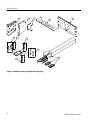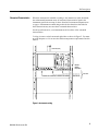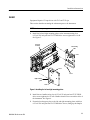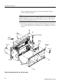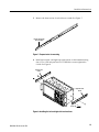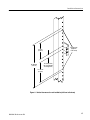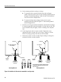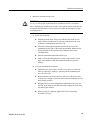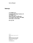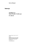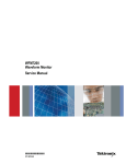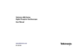
1
Instructions
RM4000
Tektronix 4000 Series Rackmount Kit
071-2134-01
Warning
The servicing instructions are for use by qualified
personnel only. To avoid personal injury, do not
perform any servicing unless you are qualified to
do so. Refer to all safety summaries prior to
performing service.
www.tektronix.com
*P071213401*
071213401
Copyright © Tektronix. All rights reserved. Licensed software products are owned by Tektronix or its subsidiaries or
suppliers, and are protected by national copyright laws and international treaty provisions.
Tektronix products are covered by U.S. and foreign patents, issued and pending. Information in this publication supercedes
that in all previously published material. Specifications and price change privileges reserved.
TEKTRONIX and TEK are registered trademarks of Tektronix, Inc.
Contacting Tektronix
Tektronix, Inc.
14200 SW Karl Braun Drive
P.O. Box 500
Beaverton, OR 97077
USA
For product information, sales, service, and technical support:
H In North America, call 1-800-833-9200.
H Worldwide, visit www.tektronix.com to find contacts in your area.
Service Safety Summary
Only qualified personnel should perform service procedures. Read this Service
Safety Summary and the General Safety Summary in the product service manual
or the instruction manual.
Do Not Service Alone. Do not perform internal service or adjustments of this
product unless another person capable of rendering first aid and resuscitation is
present.
To prevent the instrument and rack from falling onto the operator, two or more
installers should install the instrument into the rack cabinet. After completing the
installation procedure, the installers should verify that the instrument and rack
cabinet will not tip forward while the instrument is in the extended position.
Disconnect Power. To avoid electric shock, switch off the instrument power, then
disconnect the power cord from the mains power.
Use Care When Servicing With Power On. Dangerous voltages or currents may
exist in this product. Disconnect power and disconnect test leads before
removing protective panels, soldering, or replacing components.
To avoid electric shock, do not touch exposed connections.
RM4000 Rackmount Kit
1
Service Safety Summary
2
RM4000 Rackmount Kit
Kit Description
This introduction describes the installation of the rackmount kit to your standard
bench-top instrument.
The rackmount kit is a collection of parts that, once installed, configure the
instrument for mounting into a standard 19-inch equipment rack.
This document supports Tektronix modification: ECR31404.
Products
DPO4000 Series
MSO4000 Series
All Serial Numbers
All Serial Numbers
Kit Parts List
Table 1 lists the parts included in this rackmount kit. The parts are shown in
Figure 1.
Table 1: RM4000 Rackmount kit (see figure 1 on page 4)
Quantity
Part number
-1
1 each
386-7420-xx
PLATE, MOUNTING; RACKMOUNT LEFT
-2
1 each
386-7421-xx
PLATE, MOUNTING; RACKMOUNT RIGHT
-3
2 each
367-0525-xx
HANDLE, CARRYING; 0.375 AL, POWDER
COAT, PEKING GRAY
-4
1 each
386-7466-xx
PLATE, SUPPORT; RACKMOUNT TOP
-5
1 each
386-7467-xx
PLATE, SUPPORT; RACKMOUNT BACK
-6
12 each
211-0722-xx
SCREW, MACHINE; 6-- 32 X 0.250, PNH, 410 SS
PASSIVATED, T-- 15 TORX DR
-7
4 each
212-0577-xx
SCREW, MACHINE; 10-- 32 X 0.625, TRH, 410
SS, PASSIVATE, POZ
-8
4 each
212-0681-xx
SCREW, MACHINE; 10-- 32 X 0.25, PNH, 410
SS, PASSIVATE, T25 TORX
-9
4 each
361-1832-xx
SPACER, RECTANGULAR WASHER .888 X
1.000 X .225
-10
1 each
351-1095-xx
SLIDE ASSY; PAIR, W/STD HARDWARE KIT
AND REAR BRACKET
-11
4 each
211-0734-xx
SCREW, MACHINE; 6-- 32 X 0.250, FLH100, 410
SS PASSIVATED, T-- 10 TORX
1 each
071-2134-01
TECH MANUAL: INSTRUCTIONS, RACKMOUNT KIT, TEKTRONIX 4000 SERIES
Item
---------
RM4000 Rackmount Kit
Description
3
Kit Description
2
1
6
11
3
5
4
7
9
8
10
Figure 1: Rackmount kit parts (part appearance may vary)
4
RM4000 Rackmount Kit
Kit Description
Warranted Characteristics
When the instrument is installed according to the instructions in this document,
the rackmounted instrument meets all warranted characteristics listed in the
instrument specification except for those listed in Environmental Requirements
on page 6. Instruments mounted using methods other than those described in
these instructions may not meet their warranted characteristics.
See the specifications for your instrument model for tables of the warranted
characteristics.
Cooling air enters on the bottom and right sides as shown in Figure 2. You must
provide adequate cool air to meet the ambient temperature requirements listed in
Table 2.
Hot air out (rear)
Measure
input air
temperature
Cool air in
Figure 2: Instrument cooling
RM4000 Rackmount Kit
5
Kit Description
Environmental
Requirements
The following environmental characteristics supercede those listed in the
specifications and performance verification sections of the manual for your
instrument.
Table 2: Warranted characteristics
Characteristic
Description
Temperature, Inside Rack Cabinet
Operating
+10 _C to +45 _C (+50 _F to +113 _F)
Nonoperating
- 22 _C to +60 _C (-- 7.6 _F to +140 _F)
Shock
Operating and Non-operating
20 g, 11 ms, half sine, each axis, 3 drops
each
Clearance Requirements
The rack in which the rack adapted instrument is mounted must provide the
following clearance requirements:
H
A minimum of 8.75 in (222.25 mm) of vertical space
H
A minimum width of 17.72 in (450.09 mm) between the left- and right-front
rails in the rack
H
A minimum depth of 12.75 in (323.85 mm)
CAUTION. Adhering to these clearance requirements provides the rack-mounted
instrument with sufficient clearance for air circulation and accommodation of
the power cord and mounting hardware. Failure to provide these clearances can
result in overheating and can cause instrument faults or failure.
6
RM4000 Rackmount Kit
Kit Description
429.51 mm
(16.910 in)
559.56 mm
(22.030 in)
179.32 mm
(7.060 in)
57.84 mm
(2.277 in)
486.03 mm
(19.135 in)
480.37 mm
(18.912 in)
26.77 mm
(1.054 in)
177.80 mm
(7.00 in)
218.36 mm
(8.597 in)
465.02 mm
(18.308 in)
Figure 3: Instrument with rack adapter installed
RM4000 Rackmount Kit
7
Kit Description
8
RM4000 Rackmount Kit
Installation Instructions
This section contains the procedures needed to rackmount a DPO4000 or an
MSO4000 series instrument.
Minimum Tool and Equipment List
The following tools are required to attach the rack-adapter kit hardware, install
cabling hardware, and mount the rack-adapted instrument into a standard
equipment cabinet. All tools are standard tools that are readily available.
Table 3: Tools required for rackmount installation
Name
Description
Screwdriver handle (magnetic)
Accepts 1/4-inch hexagonal head driver tips
No. 2 Phillips or PoziDriv tip
Phillips or PoziDriv-driver tip for number 2 size screw heads
T-10 TORX tip
TORX-driver tip for T-10 size screw heads (flathead)
T-15 TORX tip
TORX-driver tip for T-15 size screw heads
T-25 TORX tip
TORX-driver tip for T-25 size screw heads
1/4-inch wrench
Wrench or nut driver can be used to install slides
Torque driver
6.5 in long shaft; accepts 1/4-inch hexagonal head driver tips
These instructions are for qualified service personnel who are familiar with
servicing the product. If you need further details for disassembling or reassembling the product, refer to the appropriate product manual. Contact your nearest
Tektronix Service Center or Tektronix Factory Service for installation assistance.
WARNING. To prevent the rackmounted instrument from tipping forward onto the
operator, install the instrument so that the operator will be able to access all of
its rear-panel connectors without pushing down on the instrument.
Verify that the rack does not become unstable with the instrument fully extended.
Do not leave the instrument extended when finished accessing the rear panel.
WARNING. To avoid electric shock, disconnect the power cord from the mains
power before removing the cover. Failure to do so could result in injury or death.
RM4000 Rackmount Kit
9
Installation Instructions
Remove
Equipment Required: Screwdriver handle with T-15 tip.
This procedure prepares the instrument for installation of the rackmount parts.
NOTE. Retain all parts removed from the instrument for later use. Some of those
parts will be reinstalled as you perform this rack conversion; store the remainder in case reconversion to a standard instrument configuration is desired at a
later time.
1. Disconnect the power cord from the rear of the instrument.
2. Remove the four T-15 TORX screws that secure the rear cover to the front
case assembly. See Figure 4.
3. Remove the rear cover.
Remove 4
screws
Front case
assembly
Rear case cover
Figure 4: Removal of rear case cover
10
RM4000 Rackmount Kit
Installation Instructions
Install
Equipment Required: Torque driver with T-15 and T-25 tips.
This section describes mounting the rackmount parts to the instrument.
NOTE. Rackmount part appearance may vary from the illustrations.
1. Install the left and right mounting plates on the instrument using four
6-32 x 0.250 inch pan head T-15 TORX-drive screws tightened to 8 in-lb.
See Figure 5.
Front case
assembly
Left mounting
plate
Screw
Screw
Screw
Right mounting
plate
Screw
Figure 5: Installing the left and right mounting plates
2. Install the two handles using four 10-32 x 0.25 inch pan head T-25 TORXdrive screws tightened to 16 in-lb. Handles should curve towards the sides of
the instrument. See Figure 6.
3. Fasten the back support plate to the left and right mounting plates with four
6-32 x 0.250 inch pan head T-15 TORX-drive screws, lining up the dimples
RM4000 Rackmount Kit
11
Installation Instructions
in the back support plate with the slots in the mounting plates. Tighten
screws to 8 in-lb. See Figure 6.
NOTE. The back support plate and top support plate have holes to facilitate
mounting optional accessories. For example, Figure 6 shows the TEK-USB-488
GPIB to USB Adapter mounted to the back support with screws. (You can also
use nylon straps to mount accessories.)
4. Install the top support plate on the left and right mounting plates using four
6-32 x 0.250 inch flathead T-10 TORX-drive screws tightened to 8 in-lb. See
Figure 6.
Top support plate
Flathead
screws (4)
Optional
accessory
Handle (2)
Back support
plate
Screws (4)
Screws (4)
LIne up
Figure 6: Installing the handles, top, and back support
12
RM4000 Rackmount Kit
Installation Instructions
5. Remove the front section of each of the two tracks. See Figure 7.
Remove this section
from each track.
Figure 7: Prepare tracks for mounting
6. Install the front left- and right-side track sections on the instrument using
four 6-32 x 0.250 inch pan head T-15 TORX-drive screws tightened to
8 in-lb. See Figure 8.
Left-- side rack
mount
Right-- side rack
mount
Screws (4)
Figure 8: Installing the left- and right-side track sections
RM4000 Rackmount Kit
13
Installation Instructions
WARNING. To ensure that the rackmount track locks, make sure the track button
latches are oriented correctly: the right-side latch is located toward the bottom
of the rackmount panel and the left-side latch is located toward the top of the
rackmount panel. Refer to Figure 9. If the button latches are not oriented
correctly the instrument could slide from the rack, which could cause injury or
damage to the instrument.
Note: Button latch is
located near the bottom
edge of right-side track,
top edge for left-side track.
Mount the tracks on the
sides of the instrument.
Figure 9: Track orientation
This completes the installation of the rack-adapter hardware to the instrument. To
complete the installation, do the following procedure: Rackmount the RackAdapted Instrument.
14
RM4000 Rackmount Kit
Installation Instructions
Rackmount the Rack-Adapted Instrument
This procedure assembles and installs the slide-out tracks in the equipment rack,
and then installs the rack-adapted instrument in the rack.
The slide-out tracks permit the rack-adapted instrument to be extended out of the
rack for rear-panel and connector maintenance without removing the instrument
from the rack.
WARNING. To prevent the rackmounted instrument from tipping forward onto the
operator, install the instrument so that the operator will be able to access all of
its rear devices without pushing down on the instrument.
Verify that the rack does not become unstable with the instrument fully extended.
Do not leave the instrument extended when finished accessing the rear panel.
Install Track Assembly
and Instrument into the
Rack
Equipment Required: One screwdriver handle, one number two PoziDriv tip, and
one torque driver.
NOTE. The rack hardware kit contains hardware for mounting the instrument in
several configurations. Not all of the hardware in the kit will be needed.
A standard equipment rack has rails with universal hole spacing. If you use a
rack with other than universal hole spacing, you may have to drill additional
mounting holes in the rack.
Procedure:
1. Assemble the slide-out track:
a. Measure the distance between the front and rear rail of the equipment
rack.
b. Align the rear bracket to the right slide-out track as shown in Figure 10.
Note that the rear bracket has multiple pairs of mount-through holes.
When aligning the bracket and track, be sure to select a pair of holes that
mount the rear bracket so that the flange-to-flange distance matches the
distance between the front rail and rear rail measured in step a.
c. Using a screwdriver with a number two PoziDriv tip, secure the rear
bracket to the right slide-out track using two screws (10-32) and a bar
nut as illustrated. Leave the screws loose so that the overall length of the
slide-out track assembly can be adjusted when installing it in the rack.
d. Repeat steps b and c to assemble the left slide-out track assembly.
RM4000 Rackmount Kit
15
Installation Instructions
2. Mount the slide-out track assemblies, using the slide drawer hardware listed
in the kit parts list, Figure 1-10:
a. Select the mounting position in rack: Select two 0.5 inch-spaced holes in
the front rail. Verify that the 4.36 inch and 10.500 inch clearances exist
relative to those mounting holes. See Figure 11 on page 17.
Rear flange (mounts to
rear rail of rack)
Bar nut
Flange-to-Flange: 514.4 mm (20.25 in) minimum
to 673.1 mm (26.50 in) maximum
Rear bracket
Right slide-out track assembly
Outer track
Round cut out
Front flange (mounts to
front rail of rack)
Inner track
Left slide-out track assembly
Figure 10: Assembly of slide-out track assemblies
16
RM4000 Rackmount Kit
Installation Instructions
Securing holes
(tapped for
10-32 screws)
76.2 mm
(3.000 in)
12.7 mm (0.50 in)
(for correct position
of securing holes)
221.488 mm
(8.720 in)
111.125 mm
(4.375 in)
Figure 11: Vertical clearances for rack installation (left-front rail shown)
RM4000 Rackmount Kit
17
Installation Instructions
b. Select mounting method according to rack type:
H
To mount the slide-out tracks with their front and rear flanges
outside of the front and rear rails, use the mounting method A shown
in Figure 12 when doing substep c. Add a bar nut to the installation
only if the rails have untapped holes.
H
To mount with front and rear flanges inside of rails, use the
mounting method B outlined in Figure 12. This mounting method
assumes untapped holes.
c. Install in rack: Using the method and hardware determined from substep
b, secure the right slide-out track assembly to its front and rear rails. The
screws should be fully, but lightly, seated so mounting can be adjusted
later.
d. Fix the length of the slide-out track assembly: Tighten the screws,
applying 28 inch-lb of torque, left loose in step 1, substep c to fix the
front to rear flange spacing of the slide-out track assembly.
e. Mount the left slide-out track assembly: Repeat substeps c through d to
mount the left slide-out track assembly.
Outer track
Outer track
Use a bar nut if front rails
are not tapped
Use a bar nut
Front flange
Front flange
Left-front
rack rail
English
10-32 Pan-head
screws (4)
# 12
# 10
Metric
M6
Left-front
rack rail
M5
10-32 Flat-head
screws (4)
10-32 Pan-head
screws (4)
Use two flat-head screws if the cabinet rails have
countersunk mounting holes; otherwise use two
pan-head screws
Mounting Method A
Mounting Method B
Figure 12: Installation of slide-out track assemblies in rack (top view)
18
RM4000 Rackmount Kit
Installation Instructions
3. Mount the instrument in the rack:
WARNING. To prevent the instrument from tipping or dropping onto the installers, two or more people should install this instrument into the rack cabinet.
After completing the installation procedure, the installers should verify that the
instrument and rack cabinet will not tip forward while the instrument is in the
extended position.
a. Install the instrument:
H
Working from the front of the rack, slide the inner track of each
slide-out track assembly until it extends out the front of the rack.
Continue to slide them out until they lock.
H
Insert the left and right tracks that extend from the rear of the
instrument into the ends of the tracks just extended. Make sure the
tracks mounted on the instrument slip inside the inner tracks
extended earlier.
H
Slide the instrument backwards until it stops.
H
Push to release the button latches, located on the outside of each
track, and continue to slide the instrument all the way into the
cabinet.
b. Level the rackmounted instrument:
RM4000 Rackmount Kit
H
Tighten the four screws that were left loose at the rear of the rack
when you did step 2, substep c, and then pull the instrument part
way out of the rack.
H
Be sure that the four screws that were left loose at the front of the
rack are loose enough to allow the slide-out track assemblies to seek
their normal positions.
H
Retighten the four screws and push the instrument all the way into
the rack. If the tracks do not slide smoothly, readjust the level using
the method just detailed.
H
When leveling is completed, tighten the 10-32 screws using
28 inch-lb of torque.
19
Installation Instructions
Finishing the Installation
It is recommended that you secure the instrument to the rack.
WARNING. To prevent the rackmounted instrument from sliding forward and
causing personal injury or instrument damage, always secure the instrument to
the rack if the rack is moved (for example, if the rack is repositioned or relocated
to another room).
4. Secure the instrument to the rack:
a. Secure the instrument in the rack using four 10-32 x 0.625 in screws and
rectangular washer spacers as shown in Figure 13.
Rectangular
washer
spacer (4)
Screws (4)
Figure 13: Securing the instrument to the rack
g
20
End of document g
RM4000 Rackmount Kit