1
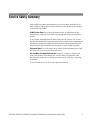
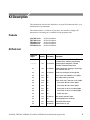
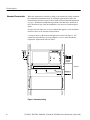
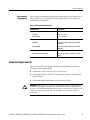
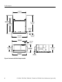
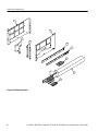
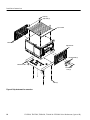
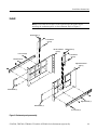
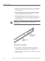
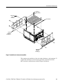
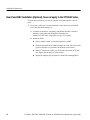
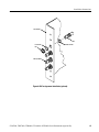
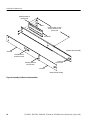
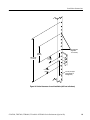
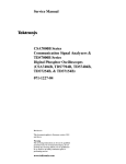
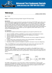
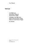
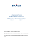
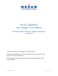
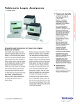
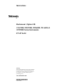
Instructions
Rackmount (Option 1R)
CSA7000, TDS7000, TDS6000, TLA600, &
OTS9000 Series Instruments
071-0716-04
Warning
The servicing instructions are for use by qualified
personnel only. To avoid personal injury, do not
perform any servicing unless you are qualified to
do so. Refer to all safety summaries prior to
performing service.
www.tektronix.com
*P071071604*
071071604
Copyright © Tektronix, Inc. All rights reserved.
Tektronix products are covered by U.S. and foreign patents, issued and pending. Information in this publication supercedes
that in all previously published material. Specifications and price change privileges reserved.
Tektronix, Inc., P.O. Box 500, Beaverton, OR 97077
TEKTRONIX and TEK are registered trademarks of Tektronix, Inc.
Service Safety Summary
Only qualified personnel should perform service procedures. Read this Service
Safety Summary and the General Safety Summary in the product service manual
or the instruction manual.
Do Not Service Alone. Do not perform internal service or adjustments of this
product unless another person capable of rendering first aid and resuscitation is
present.
To prevent the instrument and rack from falling onto the operator, two or more
installers should install the instrument into the rack cabinet. After completing the
installation procedure, the installers should verify that the instrument and rack
cabinet will not tip forward while the instrument is in the extended position.
Disconnect Power. To avoid electric shock, switch off the instrument power, then
disconnect the power cord from the mains power.
Use Care When Servicing With Power On. Dangerous voltages or currents may
exist in this product. Disconnect power, remove battery (if applicable), and
disconnect test leads before removing protective panels, soldering, or replacing
components.
To avoid electric shock, do not touch exposed connections.
CSA7000, TDS7000, TDS6000, TLA600 & OTS9000 Series Rackmount (Option 1R)
1
Service Safety Summary
2
CSA7000, TDS7000, TDS6000, TLA600 & OTS9000 Series Rackmount (Option 1R)
Kit Description
This introduction describes the installation of option 1R (rackmount kit) to your
standard bench-top instrument.
The rackmount kit is a collection of parts that, once installed, configure the
instrument for mounting into a standard 19-inch equipment rack.
Products
All Serial Numbers
All Serial Numbers
All Serial Numbers
All Serial Numbers
All Serial Numbers
CSA7000 Series
TDS7000 Series
TDS6000 Series
TLA600 Series
OTS9000 Series
Kit Parts List
Figure 3 on
page 8
Quantity
Part number
Description
---------
1 ea
016-1790-XX
Rackmount Kit: CSA7000, TDS7000, TDS6000
& TLA600 Series, consisting of the following:
---------
1 ea
071-0716-XX
Technical manual: Instructions, CSA7000,
TDS7000, TDS6000 &TLA600 Series
3-1
1 ea
441-2229-00
Rackmount panel set consisting of: left and right
side; and lower cover trim
3-2
1 ea
351-0313-01
Guide rack, consisting of: left and right side
3-3
4 ea
NS
Screw, mach: 10-32, panhead, 0.5 in l, phillips
3-3
7 ea
NS
Nut, locking washer: 10-32 assem
3-3
14 ea
NS
Screw, mach: 10-32, Truss-head, 0.5 in l, phillips
3-3
4 ea
NS
Screw, mach: M6 x 20 ovl head, phillips
3-3
4 ea
NS
Screw, mach: M5 x 20 ovl head, phillips
3-3
4 ea
NS
Screw, mach: 10-32 x 0.75 ovl head, phillips
3-3
4 ea
NS
Screw, mach: 12-32 x 0.75 ovl head, phillips
3-3
5 ea
NS
Washer: flat, nylon
3-4
1 ea
351-0241-01
Slide, drawer, extenders: Sliders
3-4
1 ea
NS
Rack: Mounting screws, nut blocks
3-5
2 ea
386-7279-00
Plate: ABS, bracket spacer
3-6
2 ea
367-0525-00
Handle: bracket, al, gray
NS - Not Saleable
CSA7000, TDS7000, TDS6000, TLA600 & OTS9000 Series Rackmount (Option 1R)
3
Kit Description
Warranted Characteristics
When the instrument is installed according to the instructions in this document,
the rackmounted instrument meets all warranted requirements listed in the
instrument specification except for those listed in Environmental Requirements
on page 5. Instruments mounted using methods other than those described in
these instructions may cause the instrument to not meet its warranted requirements.
See Specification in the user or service manual that applies to your instrument
model for tables of the warranted characteristics.
Cooling air enters on the bottom and right sides as shown in Figure 1. You
assume the responsibility to provide adequate cool air to meet the ambient
temperature requirements listed in Table 1.
Hot air out
Measure
input air
temperature
Cool air in
Figure 1: instrument cooling
4
CSA7000, TDS7000, TDS6000, TLA600 & OTS9000 Series Rackmount (Option 1R)
Kit Description
Environmental
Requirements
The following environmental characteristics supercede those listed in the user or
service manual for your instrument. The following table does not apply to the
OTS9000 Series instruments.
Table 1: Warranted characteristics
Characteristic
Description
Temperature, Inside Rack Cabinet
Operating
+10_ C to +45_ C
Non-operating
- 22_ C to +60_ C
Vibration
Operating
0.24 g rms, from 5 to 500 Hz, 10 minutes
each axis
Non-operating
2.22 g rms, from 5 to 500 Hz, 10 minutes
each axis
Shock
Operating and Non-operating
20 g, 11 ms, half sine, each axis, 3 drops
each
Clearance Requirements
The rack in which the rack adapted instrument is mounted must provide the
following clearance requirements:
H
A minimum of 266.7 mm (10.5 in) of vertical space.
H
A minimum width of 448 mm (17 5/8 in) between the left- and right-front
rails in the rack.
H
A minimum inside height depth of at least 508 mm (20 in).
WARNING. Adhering to these clearance requirements mounts the rack-adapted
instrument with sufficient clearance for air circulation and accommodation of
the power cord and mounting hardware. Failure to provide these clearances can
result in overheating and can cause the instrument to not operate properly
and/or fail.
CSA7000, TDS7000, TDS6000, TLA600 & OTS9000 Series Rackmount (Option 1R)
5
Kit Description
421.64 mm
(16.80 in)
531.925 mm
(20.925 in)
471.170 mm
(18.550 in)
424.053 mm
(16.695 in)
50.80 mm
(2.00 in)
500.024 mm
(19.686 in)
482.600 mm
(19.000 in)
161.925 mm
(6.375 in)
60.325 mm
(2.375 in)
30.480 mm
(1.200 in)
258.639 mm
(10.160 in)
265.938 mm
(10.470 in)
465.480 mm
(18.326 in)
29.72 mm
(1.170 in)
Figure 2: instrument with Rack Adapter Installed
6
CSA7000, TDS7000, TDS6000, TLA600 & OTS9000 Series Rackmount (Option 1R)
Installation Instructions
This section contains all procedures needed to rackmount the CSA7000,
TDS7000, TDS6000 and TLA600 Series instruments.
Minimum Tool and Equipment List
The following tools are required to attach the rack-adapter kit hardware, install
cabling hardware, and mount the rack-adapted instrument into a standard
equipment cabinet. All tools are standard tools that are readily available.
Table 2: Tools required for rackmount installation
Item
no.
Name
Description
1
Screwdriver handle
(magnetic)
Accepts 1@4 inch hex-head driver tips
2
No. 2 Phillips or
Pozidriv tip
Phillips or Pozidriv-driver tip for number 2 size screw heads
3
T-15 Torx tip
TorxR-driver tip for T-15 size screw heads
4
3/
8
Wrench or nutdriver can be used to install slides
inch wrench
These instructions are for personnel who are familiar with servicing the product.
If you need further details for disassembling or reassembling the product, refer to
the appropriate product manual. Contact your nearest Tektronix Service Center
or Tektronix Factory Service for installation assistance.
WARNING. To prevent the rackmounted instrument from tipping forward onto the
operator, install the instrument so that the operator will be able to access all of
its rear devices without pushing down on the instrument.
Verify that the rack does not become unstable with the instrument fully extended.
Do not leave the instrument extended when finished accessing the rear panel.
CSA7000, TDS7000, TDS6000, TLA600 & OTS9000 Series Rackmount (Option 1R)
7
Installation Instructions
1
1
6
5
2
2
3
4
4
Figure 3: Rackmount kit parts
8
CSA7000, TDS7000, TDS6000, TLA600 & OTS9000 Series Rackmount (Option 1R)
Installation Instructions
Remove
Strip the Instrument for
Conversion
Equipment Required:Torxdriver with T-15 tip (Items 1 and 3).
NOTE. All parts removed from the instrument in this procedure should be
retained for later use. Some of those parts will be reinstalled as you perform this
rack conversion. The remainder should be stored in case reconversion to a
standard instrument configuration is desired at a later time.
Right-side or left-side references in these instructions assume you are viewing
the instrument from the front panel.
1. Remove the Line Cord.
2. Remove the four T-15 Torxdrive screws and snap studs that secure the top
cover, and then remove the top cover by lifting the back up while pulling
towards the rear.
3. Remove the left-side cover by sliding the cover towards the rear of the
instrument.
4. Remove the two T-15 Torxdrive screws that secure the carrying handle to the
right-side trim panel. Remove the handle and the trim panel.
5. Remove the five T-15 Torxdrive screws that secure the cabinet bottom to the
instrument. Remove the bottom-cover trim from the instrument.
CSA7000, TDS7000, TDS6000, TLA600 & OTS9000 Series Rackmount (Option 1R)
9
Installation Instructions
Screws (4)
Snap studs (4)
Top cover trim
Left-side trim
Right-side trim
Carrying handle (1)
Bottom cover trim
T-20 Torx drive
screw (2)
Screw (5)
Figure 4: Strip instrument for conversion
10
CSA7000, TDS7000, TDS6000, TLA600 & OTS9000 Series Rackmount (Option 1R)
Installation Instructions
Install
NOTE. Preassemble all sub-parts on the right and left-side panels before
installing the rackmount panels on the instrument. Refer to Figure 5.
Bracket spacer (1)
10-32 Panhead
screw (2)
Left-side rackmount
panel (1)
10-32 Lock nut (3)
Bracket spacer (1)
10-32 Panhead
screw (2)
Left inside track (1)
Right-side rackmount
panel (1)
Bracket handle (1)
Right inside track (1)
Bracket handle (1)
10-32 Lock nut (3)
Figure 5: Rackmount panel preassembly
CSA7000, TDS7000, TDS6000, TLA600 & OTS9000 Series Rackmount (Option 1R)
11
Installation Instructions
1. Reinstall the top cover by placing the front of the cover onto the instrument
first, then lower the back into place. Secure using the four T-15 Torxdrive
screws and snap studs.
2. Install the bracket handle and bracket spacer to the right-side rackmount
panel. Secure by using the two 10-32 panhead, Phillips screws, applying
15 inch-lbs of torque. Refer to Figure 5, on page 11.
3. Install the right-side rackmount track over the three screw posts on the
right-side rackmount panel. Use the six 8-32 locking-nut washer assemblies
to secure the right-side rack track onto the rackmount panel, applying
28 inch-lbs of torque.
CAUTION. To prevent the rackmount track from not locking, make sure the track
button latch is located towards the bottom of the rackmount panel.
Refer to Figure 6.
Note button latch is located
near the bottom edge of
track.
Right track
(mount on the right side of
instrument).
Figure 6: Right inside track identification
4. Install the right-side rackmount panel assembly to the right side of the
instrument. Secure it by using the four 10-32 Truss-head phillips screws,
applying 28 inch-lbs of torque. Refer to Figure 7, on page 13.
5. Repeat steps 2 through 4 to install the left-side rackmount panel, substituting
right-side to left-side.
12
CSA7000, TDS7000, TDS6000, TLA600 & OTS9000 Series Rackmount (Option 1R)
Installation Instructions
Screws (4)
Snap studs (4)
Truss head
10-32-.5
screws (8)
Top cover trim
Left-side
rackmount
assembly (1)
Right-side
rackmount
assembly (1)
Figure 7: Installation of rackmount assemblies
This completes the installation of the rack-adapter hardware to the instrument. To
complete the installation, do the following procedure: Optional Rear-Panel
BNC installation and Rackmount the Rack-Adapted Instrument.
CSA7000, TDS7000, TDS6000, TLA600 & OTS9000 Series Rackmount (Option 1R)
13
Installation Instructions
Rear-Panel BNC Installation (Optional). Does not apply to the OTS9000 Series
Perform this procedure if you wish to route the front-panel inputs to the rear
panel.
1. Orient the oscilloscope: Set the instrument so its bottom is down with the
rear of the instrument facing you.
a. Assemble the hardware: Unpackage and identify the BNC connector
hardware in the cable feed-through kit (Tektronix part
number 103-0070-XX) using Figure 8, page 15 as a guide.
b. Mount the BNCs:
14
H
Insert a rubber washer over the threaded end of a BNC.
H
Insert the threaded end of a BNC through one of the four holes in the
right rear bracket so it protrudes out the back of the bracket.
H
Install a 5@8 inch lock washer over the threads; the install the 5@8 inch
nut. Tighten the nut using a 5@8 inch wrench.
H
Repeat the subparts just performed to mount the remaining BNCs.
CSA7000, TDS7000, TDS6000, TLA600 & OTS9000 Series Rackmount (Option 1R)
Installation Instructions
Rear bracket
BNC
Lock washer
Rubber washer
Nut
BNC (installed)
Figure 8: BNC and grommet installation (optional)
CSA7000, TDS7000, TDS6000, TLA600 & OTS9000 Series Rackmount (Option 1R)
15
Installation Instructions
Rackmount the Rack-Adapted Instrument
This procedure assembles and installs the slide-out tracks in the equipment rack,
and then installs the rack-adapted instrument in the rack.
The slide-out tracks permit the rack-adapted instrument to be extended out of the
rack for rear-panel and connector maintenance without removing the instrument
from the rack.
WARNING. If slide-out track assemblies are disassembled for maintenance, do
not interchange the left and right inner tracks when reinstalling them in the left
and right outer tracks. If you do so, you will defeat the extension stop (safety
latch) feature of the tracks. Equipment could, when extended, come out of the
slides and fall from the rack, possibly causing personal injury and equipment
damage.
WARNING. To prevent the rackmounted instrument from tipping forward onto the
operator, install the instrument so that the operator will be able to access all of
its rear devices without pushing down on the instrument.
Verify that the rack does not become unstable with the instrument fully extended.
Do not leave the instrument extended when finished accessing the rear panel.
NOTE. The rack hardware kit contains hardware needed for mounting the
instrument in several configurations. All of the hardware in the kit will not be
needed.
NOTE. A standard equipment rack has rails with universal hole spacing. If you
use a rack with other than universal hole spacing, you may have to drill
additional mounting holes in the rack.
16
CSA7000, TDS7000, TDS6000, TLA600 & OTS9000 Series Rackmount (Option 1R)
Installation Instructions
Install Track Assembly
and Instrument into the
Rack
Equipment Required: One screwdriver handle (Item1), one number two pozidriv
tip (Item 2).
NOTE. The slide-out track assemblies that are included in this kit (Figure 3-4.
page 8) come partially assembled with the inner tracks inside of the outer
tracks. Leave them partially assembled to simplify their installation and to avoid
accidental swapping of their inner tracks. (See WARNING on the previous page.)
If assemblies are disassembled, use Figure 9, page 18, to match left and right
slides. (Note that when the left and right tracks are oriented as shown, the round
cutout is below the square cutout at the end of the both inner tracks.)
Procedure:
1. Assemble the slide-out track:
a. Identify the right verses left slide-out track assemblies: find the date
code label on each assembly. The assembly to be mounted in the left side
of the equipment rack (the side nearest the left side of the instrument
when it is rackmounted) has a date code that ends with “LH,” for left
hand. The right assembly has a date code ending with “RH.”
b. Measure the distance between the front and rear rail of the equipment
rack.
c. Align the rear bracket to the right slide-out track as shown in Figure 9.
Note the rear bracket has multiple pairs of mount-through holes. When
aligning the bracket and track, be sure to select a pair of holes that mount
the rear bracket so the flange-to-flange distance (see figure) matches the
front-rail to rear rail spacing of the rackmount rack just measured.
d. Using a screwdriver with a number two pozidriv tip, secure the rear
bracket to the right slide out track using two screws (10-32) and a bar
nut as illustrated. Leave the screws loose so that the overall length of the
slide-out track assembly can be adjusted when installing it in the rack.
e. Repeat substeps c and d to assemble the left slide-out track assembly.
2. Mount the slide-out track assemblies, using the slide drawer hardware listed
in the kit parts list, Figure 3-4:
a. Select the mounting position in rack: Select two ½ inch spaced holes in
the front rail. Verify that the 4.36 inch and 10.500 inch clearances exist
relative to those mounting holes. See Figure 10, page 19.
CSA7000, TDS7000, TDS6000, TLA600 & OTS9000 Series Rackmount (Option 1R)
17
Installation Instructions
Rear flange (mounts to
rear rail of rack)
Bar nut
Flange-to-Flange: 514.4 mm
(20.25 in) min to 673.1 mm
(26.50 in) max
Rear bracket
Right slide-out track assembly
Outer track
Note button latch is
closest to top of track.
Round and
square cut outs
Front flange (mounts to
front rail of rack)
Inner track
Left slide-out track assembly
Figure 9: Assembly of slide-out track assemblies
18
CSA7000, TDS7000, TDS6000, TLA600 & OTS9000 Series Rackmount (Option 1R)
Installation Instructions
Securing holes
(tapped for
10-32 screws)
162 mm
(6.375 in)
266.700 mm
(10.500 in)
29.8 mm
(1.14 in)
21.081 mm
(.830 in)
12.7 mm (.50 in).(for
correct position of
securing holes)
Figure 10: Vertical clearances for rack installation (left-front rail shown)
CSA7000, TDS7000, TDS6000, TLA600 & OTS9000 Series Rackmount (Option 1R)
19
Installation Instructions
b. Select mounting method according to rack type:
H
To mount the slide-out tracks with their front and rear flanges
outside of the front and rear rails, use method A shown in Figure 11
when doing substep c. Add a bar nut to the installation only if the
rails have untapped holes.
H
To mount with front and rear flanges inside of rails, use mounting
method B outlined in Figure 11. This mounting method assumes
untapped holes.
c. Install in rack: Using the method and hardware determined from
substep b, secure the right slide-out track assembly to its front and rear
rails. The screws should be fully, but lightly, seated so mounting can be
adjusted later.
d. Fix the length of the slide-out track assembly: Tighten the screws,
applying 28 inch-lbs of torque, left loose in step 1, substep d to fix the
front to rear flange spacing of the slide-out track assembly.
e. Mount the left slide-out track assembly: Repeat substeps a through d to
mount the left slide-out track assembly.
Left slide-out track
Left slide-out track
Use a bar nut if front rails
are not tapped
Left-front rail
English
10-32 Panhead
screws (4)
# 12
# 10
Metric
M6
Left-front rail
M5
10-32 Flat head
screws (4)
10-32 Panhead
screws (4)
Use two flat head screws if the cabinet rail have
countersunk mounting holes; otherwise use two
pan head screws
Mounting Method A
Mounting Method B
Figure 11: Installation of slide-out track assemblies in rack (top view)
20
CSA7000, TDS7000, TDS6000, TLA600 & OTS9000 Series Rackmount (Option 1R)
Installation Instructions
3. Mount instrument in rack:
WARNING. To prevent the instrument from tipping or dropping onto the installers, two or more people should install this instrument into the rack cabinet.
After completing the installation procedure, the installers should verify that the
instrument and rack cabinet will not tip forward while the instrument is in the
extended position.
a. Install the instrument:
H
Working from the front of the rack, slide the inner track of each
slide-out track assembly until it extends out the front of the rack.
Continue to slide them out until they lock.
H
Insert the left and right tracks that extend from the rear of the
instrument into the ends of the tracks just extended. Make sure the
tracks mounted on the instrument slip inside the inner tracks
extended earlier.
H
Slide the rear of the instrument backwards until it stops.
H
Push to release the button latches, located on the outside of each
track, and continue to slide the instrument all the way into the
cabinet.
b. Level the rackmounted instrument:
H
Tighten the four screws that were left loose at the rear of the rack
when you did step 2, substep c, and then pull the instrument part
way out of the rack.
H
Be sure the four screws that were left loose at the front of the rack
are loose enough to allow the slide-out track assemblies to seek their
normal positions.
H
Retighten the four screws and push the instrument all the way into
the rack. If the tracks do not slide smoothly, readjust the level using
the method just detailed.
H
When leveling is completed, tighten the 10-32 screws using
28 inch-lbs of torque.
c. Secure the instrument and install the line cord:
H
Locate and use one of the following types: 10-32 or 12-24 or M5-20
or M6-20 oval head screws. Insert each screw through its nylon
finish washer as shown on the data sheet included with the hardware
kit.
CSA7000, TDS7000, TDS6000, TLA600 & OTS9000 Series Rackmount (Option 1R)
21
Installation Instructions
g
22
H
Using a number two phillips screwdriver, install the screw/washer
assembly in one of the two mounting holes in the right front bracket.
Repeat for the second mounting hole. Tighten both screws using
25 inch-lbs of torque.
H
Install the two remaining screw/washer assemblies in the left front
bracket using the method just described.
H
Reinstall the power cord.
End of document g
CSA7000, TDS7000, TDS6000, TLA600 & OTS9000 Series Rackmount (Option 1R)