1
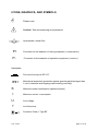
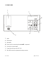
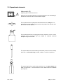
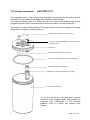
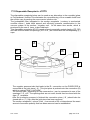
Suction- / Irrigation unit
PURGATOR 5100
MANUAL
Date: 10/2001
page 1 of 24
This manual contains proprietary information that is
protected by copyright. All rights are reserved. This
manual or excerpts thereof may not be reproduced by
photocopy, microfilm, or other means, or otherwise
distributed without the express written consent of
Tontarra Medizintechnik GmbH
Names that are registered trademarks have not been
identified as such. The absence of such identification
should not be regarded as evidence that a name is not
registered as a trademark.
Tontarra Medizintechnik GmbH would appreciate any
comments from users regarding possible errors or
unclear passages in this manual.
Since the improvement of our products is an ongoing
process, we reserve the right to make design changes
without notice.
CE - Identification as per Directive 93 / 42 / EEC
Your Dealer
Manufacturer:
GmbH • Kantstr. 33
D-78532 Tuttlingen/Germany
Tel.: +49 (0) 74 61 / 9 65 76 – 0
Fax +49 (0) 74 61 / 9 65 76 – 26
e-mail [email protected]
Internet: www.tontarra.de
Date: 10/2001
page 2 of 24
PURPOSE
The intended use of this device is to rinse and aspirate cleaning
solution during endoscopic surgical procedures.
CAUTION:
Federal (U.S.A.) law restricts this device to sale by or on the order of a
physician or other licensed practitioner
WARNINGS
•
This unit
may only be operated by properly qualified persons who have been trained in its use. Endoscopic
instruments and equipment may only be used by physicians who have completed appropriate
training.
•
Explosion Hazard
Do not use this unit in the presence of flammable gases, i.e. anesthetics.
•
Electrical Shock Hazard
Refer servicing and calibration to qualified service personnel.
•
.
•
When this device is used along with High Frequency units only non conductive
rinsing solution ( electrolyt - free ) is permitted to be used.
Due to different vicosity, the performance of suction of gas differs strongly from the
performance of suction of liquids !
•
When this unit is used in M.I.S. it is strongly recommended to use an insufflator
with audible and optical overpressure alarm capability.
•
Only fully leak proof instruments with self neutralising valves may be used in
combination with this suction / irrigation unit
.
CONTRAINDICATIONS:
* This device must not either be used for intrauterine distension nor for the
distension of other cavities in human beings
* The use of this device is contraindicated whenever forced suction and irrigation is
contraindicated.
Date: 10/2001
page 3 of 24
ICONS, GRAPHICS, AND SYMBOLS
Please note!
Caution! See accompanying documentation!
Hydrophobic, sterile filter
P+
Connector for the adaption of rinsing equipment ( overpressure )
P-
Connector for the adaption of aspiration equipment ( vacuum )
Nameplate:
Fine-wire fuse as per IEC 127
IP41
Mechanical protection (protection against granular particles larger than
1 mm in diameter and dripping water entering vertically)
S
Maximum power consumption (apparent power)
I
U
f
Maximum current consumption
Line voltage
Line frequency
Protection Class I, Type BF
Date: 10/2001
page 4 of 24
Dear customer,
Please read these instructions carefully before you put your new unit into operation for the first time.
This will prevent damage that can result from the wrong electrical connection or improper use.
Use the suction / irrigation unit only for the purposes described in these instructions. We will assume no
liability for damage caused by using the unit for purposes other than those for which it was designed.
THIS MANUAL DOES NOT CONTAIN A DETAILED DESCRIPTION OF
ENDOSCOPY AND IS NOT SUITABLE FOR INTRODUCING A BEGINNER TO THIS
SURGICAL TECHNIQUE.
. . . . . . . . . . . . . . . . . . . . . . . . . . . . . . . . . . . . . . . . . . . . . . . . . . .
CONTENTS
Page
1. PURPOSE
6
2. INITIAL USE
7
3. USING THE UNIT
9
4. FUNCTION CHECK
12
5. APPLICATION / NOTES
13
6. CARE, MAINTENANCE, AND SERVICE
16
7. ACCESSORIES
18
8. TECHNICAL DATA
23
9. TECHNICAL DOCUMENTATION
24
Date: 10/2001
page 5 of 24
1. PURPOSE
According to the regulations of classical surgery, this unit is intended to issue rinsing
solutions ( which preferably have been pre-heated to body temperature ) in order to
maintain a clear view of the operation field for the operator and also to aspirate
secretions and blood / or tissue particles with the contaminated rinsing solutions.
This manual describes an irrigation / aspiration pump that gives the user various
methods of use but is simple to handle.
.
. . . . . . . . . . . . . . . . . . . . . . . . . . . . . . . . . . . . . . . . . . . . . . . . . . .
This device must not be used for intrauterine distension
nor for the distension of other cavities in human beings
. . . . . . . . . . . . . . . . . . . . . . . . . . . . . . . . . . . . . . . . . . . . . . . . . . .
. . . . . . . . . . . . . . . . . . . . . . . . . . . . . . . . . . . . . . . . . . . . . . . . . . .
The user is responsible for selecting a suitable wash.
. . . . . . . . . . . . . . . . . . . . . . . . . . . . . . . . . . . . . . . . . . . . . . . . . . .
Hint:
The unit is tested according to and complies with DIN EN 60601-1-2. Nevertheless we
recommend to turn off unused equipment around.
Date: 10/2001
page 6 of 24
2. INITIAL USE
Receiving Inspection Inspect the unit and accessories included for obvious
damage or missing parts immediately after receiving them.
Damage claims can only be acknowledged if the supplier is
notified immediately (within 24 hours).
Always use the original packaging if you must return the
unit or accessories.
Describe the fault or malfunction, and name a person who
we may contact in the event of any questions.
Setting up the Unit
Place the unit on a clean and level surface. Ambient
temperature should be between 10 0C and 40 0C and
relative humidity between 30% and 85%.
. . . . . . . . . . . . . . . . . . . . . . . . . . . . . . . . . . . . . . . . . . . . . . . . . .
Do NOT use the unit in areas where there is danger of explosion.
. . . . . . . . . . . . . . . . . . . . . . . . . . . . . . . . . . . . . . . . . . . . . . . . . .
The suction / irrigation unit can also be attached to an
approved stand such as Item #0500 instead of setting it up
on a tower or carrier cart.
The control unit is fastened to the bearing plate #0510 with
two M 4x16 milled screws (with 12 to 16 mm of thread).
To ensure stability, all components should be fastened
below the sleeve.
The bottle holders can be fastened to the side of the unit
case with the wheel screws included. If the pump is fitted
onto an infusion stand the bottle holder should not be
screwed onto the unit for stability reason.
By means of a optional fitting kit, the bottle holder can
alternatively be fixed directly onto the groove of various
common unit trolleys. The latter method has the advantage
that, the containers are more easily accessible if the suction
/ rinsing pump is integrated into a tower system.
Date: 10/2001
page 7 of 24
Connection to Power Supply
. . . . . . . . . . . . . . . . . . . . . . . . . . . . . . . . . . . . . . . . . . . . . . . . . .
BEFORE beginning operation for the first time, check
whether the site voltage matches the voltage range
specified on the nameplate.
. . . . . . . . . . . . . . . . . . . . . . . . . . . . . . . . . . . . . . . . . . . . . . . . . .
The power connection must have a grounding contact.
Please use the power cord supplied with the unit or an
equivalent cord.
The insufflator is equipped with a rear panel socket that
complies with DIN 42801. Use this socket to ground the unit
according to local safety regulations.
Units of the SYSTEM
line can be cascaded from the
power supply (i.e., each additional unit may be connected to
the previous one). This reduces the number of cords
required and allows you to switch all connected units on or
off at the same time.
. . . . . . . . . . . . . . . . . . . . . . . . . . . . . . . . . . . . . . . . . . . . . . . . . .
The TOTAL connected loads of all cascaded units (see
nameplates) may not exceed the connected load specified on the
rear panel of the unit.
. . . . . . . . . . . . . . . . . . . . . . . . . . . . . . . . . . . . . . . . . . . . . . . . . .
. . . . . . . . . . . . . . . . . . . . . . . . . . . . . . . . . . . . . . . . . . . . . . . . . .
Authorized service personal must verify that the cascade complies
with electrical threshold values specified by IEC 601-1-1 BEFORE
you begin operation with cascaded units for the first time ( use
units ).
ONLY SYSTEM
. . . . . . . . . . . . . . . . . . . . . . . . . . . . . . . . . . . . . . . . . . . . . . . . . .
Connectors
At ist front panel, the unit is equipped with Luer Lock
connectors for the adaption of irrigation and aspiration
vessels.
In order to avoid unintended interchange the tubing set as
well as the connectors at the front panel are coded:
Luer Lock male:
Luer Lock female:
Date: 10/2001
Aspiration ( Vacuum outlet )
Irrigation ( Pressure outlet )
page 8 of 24
3. OPERATING THE UNIT
3.1 FRONT VIEW
A
P
B
C
A - Graphics of application
B - Luer Lock connector male ( vacuum )
C - Luer Lock connector female ( overpressure )
P - Power switch
Date: 10/2001
page 9 of 24
3.2 REAR VIEW
T
V
W
Max.
Anschlußleistung
300 VA
Y
EXHAUST
Netzanschluß
VOR
Öffnen des Gehäuses
IMMER erst Netzstecker ziehen!
X
Z
U
T - Label
U - Exhaust port
V - Nameplate
W - Power outlet for connecting other SYSTEM
components
X - Connection to power supply
Y - Fuses (fine-wire fuse as per IEC 127)
Z - DIN 42801 socket for equipotential bonding conductor
Date: 10/2001
page 10 of 24
3.3 Operational elements
Mains switch ( P )
Lights up green when the unit is on.
When the unit has been switched on the pump begins to run immediately if
at least one of the two luer lock connections is open
This symbol stands for hydrophobic sterile filter that must always be on
both luer lock connections in order to protect the patient from infection and
the suction unit from pollution.
.
This symbol stands for the original glass suction receptacle. Other vacuum
resistant suction containers, that are suitable for medicine technical
disciplines may also be used.
The symbol stands for suction/rinsing instruments (common on the market)
that have a self neutralising ( trumpet ) valve to contol the liquid flow..
The symbol stands for a sterile rinsing solution in a 1 litre glass bottle with
fitted puncture tube. Puncture tubes for other bottle sizes are available
upon request.
Date: 10/2001
page 11 of 24
4. FUNCTION CHECK
The function check helps to ensure that the unit is ready for
use. This should be done prior to any clinical application.
Control Unit
Connect unit to power supply and switch on power switch.
• Power switch lights up in green.
•
When even one of the Luer Lock connectors is left open, the
pump is working ( humming sound )
Close both luer lock connections so that they are airtight. (e.g. with
moistened finger)
• Pumping noise immediately stops ( pump becomes turned off )
• Free the connections alternately. The pump begins to operate
again.( Pump noise can be heared )
Suction lid
Turn the suction cap - without connected tubing set and secretion
collection bottle 180°. (i.e. upside down)
• The suction lid must be dry.
• If there is an integrated mechanical valve (e.g. a swimmer) this
must be easily movable and must close itself due to the force of
gravity.
Close the secretion receptacle with the suction lid.
• Make sure that the suction lid fits tightly.
• The suction lid should fit into the bottle neck smoothly (maybe
the O-rings on the suction lid need to be lubricated with silicon
oil - if so, take care of sterile conditions !
Complete System
Build up the complete system according to the graphic on the front
of the unit ( don’t forget the filters! ) and turn on the unit.
• The pressure ratings must be reached within 45 seconds and
the pump is turned off - if not check for leakage !
• The irrigation tubings must be flushed by the instigation of a
rinsing process (outside the body)
• Check the suction process in the atmosphere (sucking noise,
pump begins again)
. . . . . . . . . . . . . . . . . . . . . . . . . . . . . . . . . . . . . . . . . . . . . . . . . . .
Do not use the unit if , faults or malfunctions are present or
suspected, or the unit is obviously damaged.
Have the unit repaired by authorized service personnel.
. . . . . . . . . . . . . . . . . . . . . . . . . . . . . . . . . . . . . . . . . . . . . . . . . . .
Date: 10/2001
page 12 of 24
5. APPLICATION / NOTES
5.1 Functional principles
Rinsing:
The filter frees the air from bacteria, and this is pressed onto the surface of a
sterile rinsing liquid which is in a pressure resistant container ( bottle ) and thus
this solution is forced out of the rinsing solution container in the direction of the
patient
-
If the rinsing solution container is empty, the unit carries sterile air
(approx. 4 ltr./min.) to the patient ( that is if the sterile filter is fitted
correctly ! )
. . . . . . . . . . . . . . . . . . . . . . . . . . . . . . . . . . . . . . . . . . . . . . . . . . .
No alarm signal is evident !
. . . . . . . . . . . . . . . . . . . . . . . . . . . . . . . . . . . . . . . . . . . . . . . . . . .
-
This means, that if an unsuitable or faulty Instrument is used (e.g. if the
closing mechanism is not closed properly or leaks) and even if the
rinsing solution is used up, this can result in an unwanted insufflation
source , which may not have been noticeable at first.
. . . . . . . . . . . . . . . . . . . . . . . . . . . . . . . . . . . . . . . . . . . . . . . . . . .
Only suction and rinsing tubes with self neutralizing ( trumpet- ) valves may be
used !
. . . . . . . . . . . . . . . . . . . . . . . . . . . . . . . . . . . . . . . . . . . . . . . . . . .
Suction:
An (under) pressure secretion reception container is partly evacuated by a pump.
If the suction conduit is open (e.g. by means of a trumpet valve) the under
pressure maintains a suction process in the direction of the container.
- Because of the different densities of the suction material ( gas / liquids ),
the suction capacity varies considerably. In order to avoid an uncontrolled collapse of the pneumoperitoneum, gas should only be sucked off
periodically.
. . . . . . . . . . . . . . . . . . . . . . . . . . . . . . . . . . . . . . . . . . . . . . . . . . .
Please take care to notice the pressure indication of the insufflator used during
the operation by endoscopic or laparoscopic surgical operations !
. . . . . . . . . . . . . . . . . . . . . . . . . . . . . . . . . . . . . . . . . . . . . . . . . . .
Date: 10/2001
page 13 of 24
5.2 How to proceed
. . . . . . . . . . . . . . . . . . . . . . . . . . . . . . . . . . . . . . . . . . . . . . . . . . .
Do not use the unit if possible contamination is suspected, faults or
malfunctions are present or suspected, or the unit is obviously
damaged.
Have the unit repaired by authorized service personnel.
. . . . . . . . . . . . . . . . . . . . . . . . . . . . . . . . . . . . . . . . . . . . . . . . . . .
The procedure for conventional, open surgical operations and endoscopic surgical operations, using
suction / rinsing units is documented in the appropriate literature. This section is only intended to draw
your attention to some unit specific procedures:
•
Make yourself familiar with this system ahead of any initial operation.
•
Perforation with the puncture tube should not be done when the rinsing liquid bottle is in the
bottle holder, but the bottle should be placed on a stable surface.
•
Easy replacement of an empty bottle. Simply remove the puncture tube from the empty bottle,
without disconnecting the adapter tubings, and puncture a new one.
. . . . . . . . . . . . . . . . . . . . . . . . . . . . . . . . . . . . . . . . . . . . . . . . . . .
TAKE CARE OF STERILE CONDITIONS !
. . . . . . . . . . . . . . . . . . . . . . . . . . . . . . . . . . . . . . . . . . . . . . . . . . .
•
Always begin each OP with a fresh, and for this full and sterile, solution bottle.
•
Always have a reserve bottle with rinsing solution (preferably pre-warmed to body
temperature) ready, near the unit.
•
When the suction/rinsing apparatus has been turned off at the mains the ( under- ) pressure
conditions remain in the connected bottles / receptacles.
Therefore always remove the tubes that lead towards the apparatus first ( so that the
connected bottles can release pressure). The same applies when bottles are exchanged
during an operation.
•
The adaption of hydrophobic sterile filters at the inlet ( P- ) and outlet ( P+ ) of the apparatus is
obligate to avoid contamination of saline solution and of the vacuum system of the apparatus.
•
Rinsing pressure and suction vacuum are always permanently existent when the unit is
switched on. This means, that only suction and aspiration instruments with integrated (i.e. self
neutralising ) valves can be used.
•
The surgeon must choose the type and model of suction and aspiration instruments
respectively the instrument combination, depending on the intended use. (e.g. stronger or
softer spray etc.)
Date: 10/2001
page 14 of 24
•
The suction tube used must at least have a bypass opening that prevent tissue being sucked
up.
•
If only either suctioning or rinsing is required, the function that is not needed can be
„switched off “ by permanently closing the unused Luer Lock connector ( e.g. with a Luer Lock
cap ). The pressure or vacuum control will then only occur at the activated connection.
NOTES:
Date: 10/2001
page 15 of 24
6. CARE, MAINTENANCE, AND SERVICE
Care
In addition to proper operation and servicing, effective protection of the unit
against damage includes setting the unit up safely at the site. This means
securely setting up the unit on its supporting surface but also includes
protecting the unit from moisture, dirt, and contact with flammable or
explosive materials.
To ensure that the heat generated during use dissipates properly, do not
cover the ventilation slits.
Cleaning
. . . . . . . . . . . . . . . . . . . . . . . . . . . . . . . . . . . . . . . . . . . . . . . . . . .
Unplug the unit before cleaning.
. . . . . . . . . . . . . . . . . . . . . . . . . . . . . . . . . . . . . . . . . . . . . . . . . . .
The exterior surface may be treated with a cleaning agent or disinfectant
that does not damage the paint. Avoid using flammable or explosive
agents. If you must use such an agent, wait until it has completely
evaporated before switching the unit on again. Make sure that no cleaning
agents ever get inside the unit.
. . . . . . . . . . . . . . . . . . . . . . . . . . . . . . . . . . . . . . . . . . . . . . . . . . .
The unit CANNOT be sterilized.
. . . . . . . . . . . . . . . . . . . . . . . . . . . . . . . . . . . . . . . . . . . . . . . . . . .
The following procedures must be performed after each use of the unit and
its accessories:
Disposable filters, tube sets and/or instruments are designed for one-time
use and must be disposed of according to the appropriate regulations.
Sterilization
Silicone tubes, Luer lock adapters, the supplied receptacle made of glass,
the suction lid ( dismantled ), the puncture tube and metal instruments are
sterilizable after being cleaned of coarse contaminants and then rinsed in
clean water and carefully dried inside and outside. For the treatment of
the polycarbonat receptacle refer to item 7.21.
They can be sterilized:
- in an autoclave ( dry air ) at 134 C or by steam sterilization at 134 C
( See the respective manufacturer's operating instructions for details ).
CAUTION:
Date: 10/2001
Silicone tubings should only be sterilized as often as labeled on its
package. Never exceed the number of uses recommended by the
manufacturer.
page 16 of 24
Inspection
The unit must be inspected by an authorized service technician at least
once a year.
In accordance with the special safety regulations for medical appliances, all
service work, such as annual inspection, repair, alterations, calibration, etc.
may be performed only by the manufacturer or persons expressly
authorized by the manufacturer.
If the user opens and endeavours to repair the unit or alterations are
carried out by unauthorized persons, this shall release us from any liability
for the operating safety of the unit.
If desired, we will provide additional technical descriptions on request or
where we feel it is required for service and repair work.
Enter all service work performed in the table Technical Service Information.
Repairing and Returning the Unit
If repairs are required, please inform us or your authorized dealer.
Pack the cleaned ( uncontaminated * ) unit ( use only the original
packaging ) and return it to us postpaid. Describe the fault or the
malfunction and name the person who we may contact in the event of any
questions.
*)
For the protection of the service personnel, and for safety during
transportation, all devices and accessories that are sent in to be repaired
must be prepaired for shipment as described in the manual. If this is not
possible, the product must be clearly marked with a contamination warning
and should be double-sealed in safety foil.
The manufacturer has the right to refuse to carry out repairs if the product
is contaminated.
Warranty
Our products are warranted to be free from defects in workmanship and
materials for 3 years from date of sale. Costs and risks of transportation
are not included in this warranty.
The manufacturer declines all liability for the operational liability and safety
of the product if it is opened, repaired, modified or in any way tampered
with by an unauthorized person. During the warranty period such actions
would render any warranty claim null and void.
. . . . . . . . . . . . . . . . . . . . . . . . . . . . . . . . . . . . . . . . . . . . . . . . . . .
When it reaches the end of its service life, this unit should be
disposed of according to the appropriate regulations.
. . . . . . . . . . . . . . . . . . . . . . . . . . . . . . . . . . . . . . . . . . . . . . . . . . .
Date: 10/2001
page 17 of 24
7. ACCESSORIES
7.1 Overview
Item NO.
SI 5100
Description
Suction / Irrigation unit
Operating Manual
Power cord, 2.5 m angled as per CEE7 Standard Sheet VII
Bottle holder for secretion receptacle 2 liters ( Polycarbonat )
Bottle holder for for 1 liter rinsing liquid bottle
Suction receptacle, 2 liters, made of Polycarbonat
Hydrophobic sterile filter with LL-connectors at both sides ( 2 pcs. )
Puncture tube
Set of silicon tubing
(4 pcs.: 1x 0,8m LL- female, 1x 0,8m LL male; 2 x 2,5m )
Optional Equipment / Replacement Parts
Item NO.
Date: 10/2001
Description
Service Manual
Power cord 0.25m, straight acc. to EN 60320
Luer Lock connector male for tubing ID 5mm
Luer Lock connector female for tubing ID 5mm
Disposable receptacle , 2 L, type HI-TEC
Bottle holder for disposable receptacle
Bottle holder for secretion bottle 2l #5114
Secretion bottle 2l ( Schott ) made of glass
Suction lid complete for #5114
Hydrophobic sterile filter with LL-connectors at both sides
page 18 of 24
7.2 Suction receptacle
# ACC3011-13
The integrated valve in the suction lid is intended as protection for the pump, so that
secretion is not sucked into the apparatus, causing contamination.
The aforementioned valve is a floater and can be found in the guiding cage that is
plugged opposite of the Luer connector at the bottom side of the the suction lid.
The suction lid can be dismantled into 3 parts and this is done by pulling off the cage
that guides the floater ( as shown below ).
Stud for the connection of suction tubing
Luer Lock connector “VAKUUM“ for the connection
of suction pump
Suction lid
Internal suction tube ( foam absorber )
washer ( do NOT remove for cleaning purposes )
overflow protection valve ( floater )
guidance for overflow protection valve ( cage )
suction container, scaled
To put the suction lid with integrated overflow
protection valve together again, just proceed the
reversed way. Lubrication of the included
washers, once in a while, will improve their
lifetime.
Date: 10/2001
page 19 of 24
7.21 Cleaning and Disinfection
Do not use disinfectants, solvants or scrubbing products for cleaning the
suction container as this may irreversibly damage the components made of
plastic.
• Do not submerge the container in disinfectant solution
• Do not use flammable or explosive agents
Cleaning
The plastic components of the suction container are made of Polycarbonat,
that resists humidity and water. Despite of this being submerged in water at
a temperature that exceeds 60 oC this may result in chemical destruction
which affects stability and reduces shock resistance capability of the product.
> Dismantle the main components of the secretion receptacle as shown in
the sketch.
> Clean the surfaces of the components with warm and sterile water from
coarse contaminants ( maximum temperature 60 oC ) and then dry
carefully with a soft and smooth clothing.
> Maximum cycle time for sterilization ( steam or dry ) is 15 minutes at a
temperature of 121 oC at 1 bar overpressure ( 100 kPa ).
Please ensure that the opening of the container is positioned downwards.
During sterilization the components mustn’t be squeezed by any kind
of loads or weights !
> After sterilization in an autoclave, the components should be allowed to
receive ambient ( room ) temperature before being used again.
> Before reassembling, visually check the components on obvious damages.
> The receptacle is now prepared für being used anew.
. . . . . . . . . . . . . . . . . . . . . . . . . . . . . . . . . . . . . . . . . . . . . . . . . . .
The suction container may be sterilized, according to the said
procedures. Maximum is 20 cycles.
. . . . . . . . . . . . . . . . . . . . . . . . . . . . . . . . . . . . . . . . . . . . . . . . . . .
Date: 10/2001
page 20 of 24
7.22 Functional check
The suction receptacle is to be checked at least every 6
months, or according to hosptal guidelines, by trained
personnel.
Overflow valve
> Connect the receptacle according to the graphic shown on the front panel
of the pump..
> Suc distilled water from a vessel, using the tubing that leads to the patient,
until the overflow protection valve becomes activated.
> Continue suction for about 2 minutes ( do not stop the pump ). The level of
water in the scaled receptacle should not become altered any more within
this timespan.
e.g. if there should be a leaking washer of the overflow protection
valve, the level of water in the receptacle would continue rising.
Check
imperviousness
> Connect the receptacle according to the graphics shown on the front panel
of the suction pump.
> Close the Luer Lock connector P+ airtight ( e.g. by a wet thumb or a Luer
Lock cap )
> Close the connector of the receptacle that leads to the patient airtight.
> Switch on the pump:
The sounding from the pump has to stop at least after 40 seconds
( using a airtight 2 liter receptacle ) and may not be repeated in
intervals of less than 30 seconds.
. . . . . . . . . . . . . . . . . . . . . . . . . . . . . . . . . . . . . . . . . . . . . . . . . . .
If there should be any detected or supposed damages to the
secretion receptacle – it mustn’t be used and has to be replaced by
a new one !
. . . . . . . . . . . . . . . . . . . . . . . . . . . . . . . . . . . . . . . . . . . . . . . . . . .
Date: 10/2001
page 21 of 24
7.3 Disposable Receptacle
# 5115
The disposable receptacle below can be used as an alternative to the reusable (glass
or Polycarbonat ) bottles.This eliminates the reconditioning of the reusable bottle and
the suction cap, preventing the noso-cosmic infection risk.
The hydrophobic filter integrated in the suction receptacle ( contrary to mechanical
overflow valves ) holds back aerosol and efficiently prevents contamination in the
vacuum system of the suction / irrigation unit. At the same time smoke, which is
produced by the use of laser, is also held back.
This disposable receptacle #5115 is made of environmentally neutral plastics (PP, PE)
and can be burnt when all openings ( B-C-D-E ) are closed with the corresponding (F)
caps.
A
E
D
B
C
F
The negative pressure tube that leads to the P- connection on the PURGATOR is
connected at the joint piece ( A ). This joint piece is pushed onto the connection (B)
which is marked "ONLY VACUUM".
The suction tube ( depending on the cross-section ) can be connected to one of the
openings C, D, or E. The openings that are not used, should then be closed with the
caps ( F ) available.
After the suctioning process is finished the connection piece ( B ) should also be
closed with a ( F ) cap, after the joint piece has been removed.
The suction receptacle ( volume 2 liter ) has a scale of 50 ml intervals and the exact
amount of secretion quantity that has been removed can be established.
Date: 10/2001
page 22 of 24
8. TECHNICAL DATA
- Line voltage:
230 Vac
- Maximum power consumption:
120 VA
- Frequency:
50 / 60 Hz
- Protection class:
1
- Protection symbol:
BF –
- Classification as per Annex IX
of Directive 93/42/EEC
IIa
- Weight:
5,0 kg
- Dimensions (H x W x D):
30 x 14.5 x 32 cm
- Operating environment:
10o ... 40o C
30% ... 80%
ambient temperature
relative humidity
- Storage and transportation environment:
– 400 C ... +700C
10% ... 90%
ambient temperature
relative humidity
- Noise emission
< 70 dB (A)
- Rinsing performance:
up to 3000 ml/min
( depending on the instruments
and tunbing used)
- Aspiration performance ( liquids ) :
( e.g. NaCl-solution ):
up to 3 l/min
(depending on the instruments
and tubing used)
- Aspiration performance (gas) :
> 20 l/min
short term
with 2 Liter secretion bottle
≈ 8 l/min
permanent
- Pressure in Rinsing bottle:
0.5 ... 1.0 bar
overpressure
- Vacuum in Secretion receptacle:
-0.3 ... -0.7 bar
vacuum
- Manufactured and tested according to:
VDE 0750-1, DIN EN 60601-1
control unit
The nameplate contains technical data such as the type and serial number of your unit, which must
always be specified when ordering replacement parts or requesting other information.
.
Date: 10/2001
page 23 of 24
9. TECHNICAL DOCUMENTATION
The unit with serial number: ________ was released to the customer on _________.
Training was conducted by Mr./Ms.: _______________________________________
The following person(s) received training:
________________________ Function: ____________________________________
________________________ Function: ____________________________________
9.1 SERVICE TABLE
Date
Description
Signature
Use additional sheet if necessary.
Further technical information only upon request for authorized persons!
Date: 10/2001
page 24 of 24