1
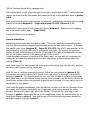
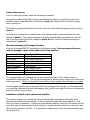
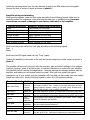
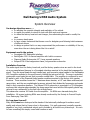
Dali Racing’s NSX Audio System
System Overview
Our design objectives were……
q to maintain the cosmetic integrity and aesthetics of the vehicle
q to enable the vehicle to return to stock with little work and expense
q to utilize the factory head unit and changer, thus eliminating the need to modify the
dash
q to conserve trunk space
q to have a basic framework that leaves room for budgetary and listening habit variances
of different drivers
q to design a system that in no way compromised the performance or reliability of the car,
even when the car is being driven like it is a rental!
Equipment used in the system
q Soundgate LOC Audiophile interface
q EarthQuake 120.2 4 channel amplifier with built-in crossover
q Diamond Audio Motorsports 6.5” 2-way separate speakers
q Eclipse 8708.4 Cast magnesium frame, long-excursion subwoofer
Installation Overview
The audio signal from the factory head unit, and the factory speaker wires are sent to the trunk
via a pre-manufactured harness to a Soundgate interface mounted in the trunk that massages the
signal. Then the signal heads through twisted pair, gold connector signal cables to the Earthquake
120.2 amplifier mounted in the area formerly holding the jack and tool kit. The amp is protected
underneath a perforated shroud that is powder-coated black. The amplifier is configured to send
85 watts to each of the Diamond Audio speaker modules mounted in the factory door speaker
locations. These modules house the 1” aluminum dome tweeter, a 6.5” cast frame mid-bass/midrange driver, and the very sophisticated crossover network that divides the frequencies and sends
them to their respective speakers. The Eclipse 8708.4 subwoofer is mounted in a CF & fiberglass
enclosure that occupies approximately the same space that once held the little spindly plastic bag
referred to as a subwoofer by the fine folks at Bose/Acura.
This subwoofer receives 200 watts from the amplifier. No NSXs were harmed during this
installation. All scenes involving NSXs were closely monitored by the Society to Prevent People
From Destroying Their NSX.
So, how does it sound?
Many NSXs have been destroyed at the hands of the technically challenged to achieve sound
quality and volume that isn’t even close to this system. It is well engineered, sonically accurate,
capable of very high, undistorted output, and is invisible to all but the very trained eye. It is rare
to have something this simple, sound and function so well!
Dali Racing’s NSX Audio System
Installation Instructions
Given the proper tools, some degree of mechanical aptitude and a little patience, this system
should be able to be installed over a weekend. Take your time, follow the directions carefully, and
be thorough and you should have no problems. If you have any doubts about your ability to do a
good job, **STOP** and contact your local high-end car stereo shop to schedule an appointment.
The following tools are recommended for the installation.
-electric or cordless drill
-#2 phillips screwdriver
-a set of drill bits
-8mm, 10mm, 12mm sockets
-pick tool set
-diagonal cutters (dykes)
Start your installation by reading through the entire installation instructions to mentally get a
picture of the entire process. Next, unpack the entire system and familiarize yourself with all of
the different components. Now you’re ready to start the installation. This is the recommended
sequence for performing the installation.
Remove the passenger seat
Set the climate control system to “Floor/Defrost”
Remove the negative battery terminal
Disassembly Instructions
The next step is the disassembly of all areas
Next, remove the following interior trim pieces by following diagram A, reprinted from the NSX
service manual.
(Bottom of page 20-38)
1. Side sill pad
2. Side sill trim
3. Rear trim panel
4. Right rear trim panel
5. Rear upper trim panel
Pull the floorboard carpet kit on passenger side.
Pull carpeted panel on side of console back far enough to access back of radio. To accomplish this,
remove the screw from the floor heater vent located at the top of the panel and shown in photos
A & E.
Next, remove the aluminum panel covering the subwoofer, and then the subwoofer and mounting
bracket by following diagram B. (Right side of page 23-238) (Photos B, C, D)
Remove the 3-piece carpet kit in the trunk by following diagram C. Make sure not to misplace
any of the plastic retainer clips.
(Page 20-66)
Remove the factory tool and jack kit
Harness installation
Remove the factory radio plug from back of radio. There are 2 methods of accomplishing this.
The first, follow the service manual instructions and remove the dash and the radio. If choosing
this painful route, follow (diagram D) Pages 23-232-233) This is NOT recommended, as it is
time consuming, and quite often leads to a scratched dash bezel. The second, and preferred
method will take a little patience and finesse. To accomplish this, grab a flashlight and your pick
tool set and position yourself on the passenger side of the console.
Locate the plastic connector on the back of the factory radio, use your pick tool to depress the
locking tab, and slide plug towards front of vehicle, and pull out to the passenger side of the
console. (Photo E)
Next, insert plug of the new harness that is the same as the factory plug, into the radio, and plug
the factory radio harness into the female jack.
Next, it’s time to route the harness to the trunk. Follow the route pictured in (photos: F, G)
The harness will pass through the front firewall in the right corner, in the large, oval grommet
pictured in photo H. The grommet would be over your right shoulder if seated in the passenger
seat. Make sure to run the harness through the top of the grommet, over the factory harness. Be
careful when cutting a slice in the grommet to pass the wires through. It is very easy to cut in to
the harness, or your fingers!
Once inside the engine compartment, route the harness over the top of the fan, securing it to the
fan bracket, and tie wrap wire securely out of harms way, while routing towards the rubber
grommet located at the upper right side of rear firewall. You can see the trunk side of this
grommet in photo I. Once inside the rear trunk compartment, secure the harness under the top
trunk lip as detailed in photo I. Note that the end of the harness ends up passing behind the
trunk latch support as shown in photo J.
Power cable harness
Prior to routing the harness, make the following connections.
Connect the positive cable (Red) to the power distribution center by removing the nut on the
farthest forward, large distribution stud shown in photo K. Make sure this connection is tight
before moving on.
Connect the ground cable (black) to the bolt on the block that holds the engine ground, shown in
photo K.
Now that your connections are made, secure your harness with tie wraps and follow the route
detailed in photo L. Your harness will pass through the unused rubber grommet at the top left
side of the front wall of the trunk, detailed in photo M. Next, route the harness following the
route shown in photo N.
Wire and mounting of Soundgate interface
Wire the Soundgate EXACTLY according to the following legend. Incorrect connections can
result in damage to your factory radio and/or the amplifier.
Harness wire colors
Unused
Blue w/white
Green w/white
Black (Connected)
Black (Connected)
Green w/black
Blue w/black
Unused
Soundgate LOC connections
Left positive lo input
Left positive high input
Left negative input
Left ground
Right ground
Right negative input
Right positive high input
Right positive lo input
The 18 gauge black wire connected to the two ground terminals on the interface must be
connected to chassis ground. This can be accomplished by securing them via the bolt on the trunk
latch support strut. Failure to connect this can result in severe engine whine through your system.
The Soundgate interface can be mounted either by screwing to the rear wall, (not recommended),
or by pushing it between the trunk latch support strut, and the rear wall of the trunk, and securing
with the enclosed, long tie-wrap.
Installation of black carpet underneath amplifier
The carpet’s purpose is to conceal the wiring to the amplifier, and make it look pretty when
showing your friends your new system. It can be secured in place with spray adhesive, or left
loose, as it can’t go anywhere. If using the spray adhesive method, spray both the carpet, and the
trunk floor with an even coating, allow to set-up for several minutes or until dry to the touch, and
then press the carpet to the floor. It is important to make sure you have the wires routed through
the opening first.
Insert the remaining wires from the main harness as well as the RCA cables from Soundgate
through the hole in center of carpet as shown in photo O.
Amplifier wiring and mounting
Next insert the speaker wires into their plugs according to the following legend. Make sure to
carefully confirm the orientation of the plug into the amp prior to installing wires. Incorrect
connections can result in damage to your factory radio and/or the amplifier.
Harness wire colors
White
Orange
White w/black
Orange w/black
Blue
Red w/white & red w/black
Black w/white & green
Amplifier speaker plug connections
Left positive on front plug
Left negative on front plug
Right positive on front plug
Right negative on front plug
REM on front plug
Left positive on rear plug
Right negative on rear plug
Next insert the power cables into their plug according to the following legend
Red: +
Black: -Next insert the RCA signal cable into the “Front” inputs
Position the amplifier in the center of the well and secure using the provided screws as shown in
photo P.
The amplifier will arrive at your door with the crossover, gain and switch settings in the optimum
positions, however, some of us like to play, so read the instructions provided with your amplifier
very carefully before touching the adjustments. Incorrect settings can damage speakers and the
amplifier, and make your new system sound very bad! After you have gotten the urge to
experiment out of your system, and the frustration with how bad you have made your new system
sound has really set in, use the following legend to return it to the optimum settings.
Function/Control
Rear xover Freq.
Rear HP/LP
Rear gain
Q-bass
Front gain
-12db
Combine
Front HP freq.
Setting
Notes
18 clicks
from full
counterclockwise
Switch out
90%
clockwise
Fully
counterclockwise
45%
clockwise
Out
In
19 clicks
from full
This is the lowpass frequency of your subwoofers. The optimum setting for
most styles of music is 73hz. Lowering it can mean less output, and poor
system frequency response. Raising it, can mean boomy, directional sub
bass that will not help create a realistic sound stage.
This switch determines whether your subwoofer is low pass or high pass.
This is the level control for the subwoofer. Adjust sparingly. Too much
gain can cause distortion and possibly damage the subwoofer and/or amp.
This dangerous control serves no purpose in your system. DON’T TOUCH
UNLESS OTHERWISE INSTRUCTED.
This is the level control of the door speakers. Adjust sparingly. Too much
gain can induce noise and distortion.
This is used when running a speaker level input to the amplifier.
This sends the output of the Soundgate to all four channels of the amp
This is the high-pass frequency of your Diamond Audio door speakers.
They are set to 80 hz. Lowering this frequency can cause distortion and
counterclockwise
possibly damage the speakers. Raising it will make the sound thinner and
less detailed.
Subwoofer installation
Next, install the subwoofer enclosure and connect its harness into the 2 pin connector on main
harness that mates with the sub connector. Attach the enclosure using the supplied blots, and the
lower two factory mounting holes.
Door speaker installation (This applies to both doors)
Remove the door panel and factory speaker units by following diagrams E-1, 2. (Pages 20-7-8)
On the speaker unit harness that remains in the door, cut the orange and white wires 1.5” from
the plug.
Next, screw the new speaker module into the door using the supplied (6) 3” long sheet metal
screws. Use the factory ½” sheet metal screws to align the unit via the factory mounting
locations, and then use the 3” screws to secure the pod as shown in photo Q.
Strip ¼” of insulation from the orange and white wires and connect to crossover mounted on door
pod according to the following diagram
Wire
Orange
White
Connect to
Negative input
Positive input
Incorrect connections will cause phase cancellation and negatively impact the sound quality of the
system.
Repeat on other door.
Turn on procedures
Reconnect the negative battery cable.
Verify amplifier settings according to the legend to make sure no buttons were accidentally
depressed.
Insert the supplied Maxi-fuse into fuse holder on main power harness
Turn the system on and proceed through the following tests.
-balance test: verify that left is left and right is right. If incorrect, reverse the RCA cables into the
amplifier.
-engine noise test: Roll up the windows, shut the doors, start the engine, and listen for any type
of whine, squeal or tic through the system. If present, make sure battery connections are tight. If
still present, contact the ThunderWorks Technical Support Hotline at (619) 596-1925.
-volume test: Turn the system on and with the bass and treble controls set to flat, and a well
recorded CD playing, turn the volume up and listen for adequate volume, good relationship
between the subwoofer and door speakers, and distortion. If needed, make adjustments, and reevaluate.
If all tests are positive, mount the perforated amplifier shroud with the ½” self-tapping screws as
shown in photo R.
Finally, reinstall the door panels, trunk carpet kit, and interior and go for a drive.