1
GE Medical Systems
Kretz Ultrasound
Technical
Publication
Direction KTI105947
Revision 2
GE Medical Systems - Kretztechnik
Voluson® 730Pro / 730ProV (BT´04)
Service Manual
• Voluson® 730Pro / 730ProV systems with Serial number A31501 - A33999
• Voluson® 730Pro / 730ProV systems with Software version SW 4.x.x
• Voluson® 730Pro / 730ProV systems that were upgraded to BT´04
• Voluson® 730Pro / 730ProV systems, upgraded to BT´05 (SW 5.x.x)
0123
Copyright© 2004, 2005 by General Electric Co.
GE MEDICAL SYSTEMS - KRETZTECHNIK
DIRECTION KTI105947, REVISION 2
VOLUSON® 730PRO / 730PROV (BT´04)
SERVICE MANUAL
Important Precautions
WARNING
AVERTISSEMENT
WARNUNG
• THIS SERVICE MANUAL IS AVAILABLE IN ENGLISH ONLY.
• IF A CUSTOMER’S SERVICE PROVIDER REQUIRES A LANGUAGE OTHER THAN
ENGLISH, IT IS THE CUSTOMER’S RESPONSIBILITY TO PROVIDE
TRANSLATION SERVICES.
• DO NOT ATTEMPT TO SERVICE THE EQUIPMENT UNLESS THIS SERVICE
MANUAL HAS BEEN CONSULTED AND IS UNDERSTOOD.
• FAILURE TO HEED THIS WARNING MAY RESULT IN INJURY TO THE SERVICE
PROVIDER, OPERATOR OR PATIENT FROM ELECTRIC SHOCK, MECHANICAL
OR OTHER HAZARDS.
• CE MANUEL DE MAINTENANCE N’EST DISPONIBLE QU’EN ANGLAIS.
• SI LE TECHNICIEN DU CLIENT A BESOIN DE CE MANUEL DANS UNE AUTRE
LANGUE QUE L’ANGLAIS, C’EST AU CLIENT QU’IL INCOMBE DE LE FAIRE
TRADUIRE.
• NE PAS TENTER D’INTERVENTION SUR LES ÉQUIPEMENTS TANT QUE LE
MANUEL SERVICE N’A PAS ÉTÉ CONSULTÉ ET COMPRIS.
• LE NON-RESPECT DE CET AVERTISSEMENT PEUT ENTRAÎNER CHEZ LE
TECHNICIEN, L’OPÉRATEUR OU LE PATIENT DES BLESSURES DUES À DES
DANGERS ÉLECTRIQUES, MÉCANIQUES OU AUTRES.
• DIESES KUNDENDIENST-HANDBUCH EXISTIERT NUR IN ENGLISCHER
SPRACHE.
• FALLS EIN FREMDER KUNDENDIENST EINE ANDERE SPRACHE BENÖTIGT, IST
ES AUFGABE DES KUNDEN FÜR EINE ENTSPRECHENDE ÜBERSETZUNG ZU
SORGEN.
• VERSUCHEN SIE NICHT, DAS GERÄT ZU REPARIEREN, BEVOR DIESES
KUNDENDIENST-HANDBUCH NICHT ZU RATE GEZOGEN UND VERSTANDEN
WURDE.
• WIRD DIESE WARNUNG NICHT BEACHTET, SO KANN ES ZU VERLETZUNGEN
DES KUNDENDIENSTTECHNIKERS, DES BEDIENERS ODER DES PATIENTEN
DURCH ELEKTRISCHE SCHLÄGE, MECHANISCHE ODER SONSTIGE
GEFAHREN KOMMEN.
Important Precautions
i
GE MEDICAL SYSTEMS - KRETZTECHNIK
DIRECTION KTI105947, REVISION 2
AVISO
ATENÇÃO
AVVERTENZA
ii
VOLUSON® 730PRO / 730PROV (BT´04)
SERVICE MANUAL
• ESTE MANUAL DE SERVICIO SÓLO EXISTE EN INGLÉS.
• SI ALGÚN PROVEEDOR DE SERVICIOS AJENO A GEMS SOLICITA UN IDIOMA
QUE NO SEA EL INGLÉS, ES RESPONSABILIDAD DEL CLIENTE OFRECER UN
SERVICIO DE TRADUCCIÓN.
• NO SE DEBERÁ DAR SERVICIO TÉCNICO AL EQUIPO, SIN HABER
CONSULTADO Y COMPRENDIDO ESTE MANUAL DE SERVICIO.
• LA NO OBSERVANCIA DEL PRESENTE AVISO PUEDE DAR LUGAR A QUE EL
PROVEEDOR DE SERVICIOS, EL OPERADOR O EL PACIENTE SUFRAN
LESIONES PROVOCADAS POR CAUSAS ELÉCTRICAS, MECÁNICAS O DE OTRA
NATURALEZA.
• ESTE MANUAL DE ASSISTÊNCIA TÉCNICA SÓ SE ENCONTRA DISPONÍVEL EM
INGLÊS.
• SE QUALQUER OUTRO SERVIÇO DE ASSISTÊNCIA TÉCNICA, QUE NÃO A
GEMS, SOLICITAR ESTES MANUAIS NOUTRO IDIOMA, É DA
RESPONSABILIDADE DO CLIENTE FORNECER OS SERVIÇOS DE TRADUÇÃO.
• NÃO TENTE REPARAR O EQUIPAMENTO SEM TER CONSULTADO E
COMPREENDIDO ESTE MANUAL DE ASSISTÊNCIA TÉCNICA.
• O NÃO CUMPRIMENTO DESTE AVISO PODE POR EM PERIGO A SEGURANÇA
DO TÉCNICO, OPERADOR OU PACIENTE DEVIDO A‘ CHOQUES ELÉTRICOS,
MECÂNICOS OU OUTROS.
• IL PRESENTE MANUALE DI MANUTENZIONE È DISPONIBILE SOLTANTO IN
INGLESE.
• SE UN ADDETTO ALLA MANUTENZIONE ESTERNO ALLA GEMS RICHIEDE IL
MANUALE IN UNA LINGUA DIVERSA, IL CLIENTE È TENUTO A PROVVEDERE
DIRETTAMENTE ALLA TRADUZIONE.
• SI PROCEDA ALLA MANUTENZIONE DELL’APPARECCHIATURA SOLO DOPO
AVER CONSULTATO IL PRESENTE MANUALE ED AVERNE COMPRESO IL
CONTENUTO.
• NON TENERE CONTO DELLA PRESENTE AVVERTENZA POTREBBE FAR
COMPIERE OPERAZIONI DA CUI DERIVINO LESIONI ALL’ADDETTO ALLA
MANUTENZIONE, ALL’UTILIZZATORE ED AL PAZIENTE PER FOLGORAZIONE
ELETTRICA, PER URTI MECCANICI OD ALTRI RISCHI.
Important Precautions
GE MEDICAL SYSTEMS - KRETZTECHNIK
DIRECTION KTI105947, REVISION 2
VOLUSON® 730PRO / 730PROV (BT´04)
SERVICE MANUAL
Important Precautions
iii
GE MEDICAL SYSTEMS - KRETZTECHNIK
DIRECTION KTI105947, REVISION 2
VOLUSON® 730PRO / 730PROV (BT´04)
SERVICE MANUAL
DAMAGE IN TRANSPORTATION - FOR USA ONLY
All packages should be closely examined at time of delivery. If damage is apparent write “Damage In
Shipment” on ALL copies of the freight or express bill BEFORE delivery is accepted or “signed for” by
a GE representative or hospital receiving agent. Whether noted or concealed, damage MUST be
reported to the carrier immediately upon discovery, or in any event, within 14 days after receipt, and the
contents and containers held for inspection by the carrier. A transportation company will not pay a claim
for damage if an inspection is not requested within this 14 day period.
CERTIFIED ELECTRICAL CONTRACTOR STATEMENT - FOR USA ONLY
All electrical Installations that are preliminary to positioning of the equipment at the site prepared for the
equipment shall be performed by licensed electrical contractors. Other connections between pieces of
electrical equipment, calibrations and testing shall be performed by qualified GE Healthcare personnel.
In performing all electrical work on these products, GE will use its own specially trained field engineers.
All of GE’s electrical work on these products will comply with the requirements of the applicable
electrical codes.
The purchaser of GE equipment shall only utilize qualified personnel (i.e., GE’s field engineers,
personnel of third-party service companies with equivalent training, or licensed electricians) to perform
electrical servicing on the equipment.
OMISSIONS & ERRORS
If there are any omissions, errors or suggestions for improving this documentation, please contact the
GE Healthcare Global Documentation Group with specific information listing the system type, manual
title, part number, revision number, page number and suggestion details.
Mail the information to:
Service Documentation, 4855 W. Electric Ave (EA-53), Milwaukee, WI 53219, USA.
GE Healthcare employees should use the iTrak System to report all documentation errors or omissions.
iv
Important Precautions
GE MEDICAL SYSTEMS - KRETZTECHNIK
DIRECTION KTI105947, REVISION 2
VOLUSON® 730PRO / 730PROV (BT´04)
SERVICE MANUAL
LEGAL NOTES
The contents of this publication may not be copied or duplicated in any form, in whole or in part, without
prior written permission of GE Medical Systems.
GE Medical Systems may revise this publication from time to time without written notice.
PROPRIETARY TO GE MEDICAL SYSTEMS
Permission to use this Advanced Service Software and related documentation (herein called the
material) by persons other than GE Medical Systems employees is provided only under an Advanced
Service Package License relating specifically to this Proprietary Material. This is a different agreement
from the one under which operating and basic service software is licensed. A license to use operating
or basic service software does not extend to or cover this software or related documentation.
If you are a GE Medical Systems employee or a customer who has entered into such a license
agreement with GE Medical Systems to use this proprietary software, you are authorized to use this
Material according to the conditions stated in your license agreement.
However, you do not have the permission of GE Medical Systems to alter, decompose or reverseassemble the software, and unless you are a GE employee, you may not copy the Material.
The Material is protected by Copyright and Trade Secret laws; the violation of which can result in civil
damages and criminal prosecution.
If you are not party to such a license agreement or a GE Medical Systems Employee, you must exit this
Material now.
TRADEMARKS
All products and their name brands are trademarks of their respective holders.
COPYRIGHTS
All Material Copyright© 2005 by General Electric Inc. All Rights Reserved.
Important Precautions
v
GE MEDICAL SYSTEMS - KRETZTECHNIK
DIRECTION KTI105947, REVISION 2
VOLUSON® 730PRO / 730PROV (BT´04)
SERVICE MANUAL
This page was intentionally left blank.
vi
Important Precautions
GE MEDICAL SYSTEMS - KRETZTECHNIK
DIRECTION KTI105947, REVISION 2
VOLUSON® 730PRO / 730PROV (BT´04)
SERVICE MANUAL
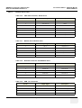
Revision History
Revision
Date
1
September 30, 2004
Initial Release (from Software Version 4.0.x onwards)
August xx, 2005
general update and modification + implementation of service conditions
for systems upgraded to BT´05 (SW 5.x.x)
2
Reason for change
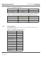
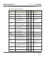
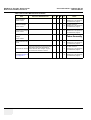
List of Effected Pages
Pages
Revision
Pages
Revision
Pages
Revision
Chapter 2 - Pre-Installation
pages 2-1 to 2-10
2
Chapter 7 - Diagnostics/Troubleshooting
pages 7-1 to 7-32
2
Title Page
2
Important Precautions
pages i to vi
2
Chapter 3 - Installation
pages 3-1 to 3-52
2
Chapter 8 - Replacement Procedures
pages 8-1 to 8-24
2
Rev History/LOEP
pages vii to viii
2
Chapter 4 - Functional Checks
pages 4-1 to 4-46
2
Chapter 9 - Replacement Parts
pages 9-1 to 9-36
2
Table of Contents
pages ix to xxvi
2
Chapter 5 - Theory
pages 5-1 to 5-56
2
Chapter 10 - Care & Maintenance
pages 10-1 to 10-26
2
Chapter 1 - Introduction
pages 1-1 to 1-12
2
Chapter 6 - Service Adjustments
pages 6-1 to 6-6
2
Index
pages I to IV
2
Back Cover
2
Revision History
vii
GE MEDICAL SYSTEMS - KRETZTECHNIK
DIRECTION KTI105947, REVISION 2
VOLUSON® 730PRO / 730PROV (BT´04)
SERVICE MANUAL
This page was intentionally left blank.
viii
Revision History
GE MEDICAL SYSTEMS - KRETZTECHNIK VOLUSON® 730PRO / 730PROV (BT´04)
DIRECTION KTI105947, REVISION 2
SERVICE MANUAL
Table of Contents
CHAPTER 1
Introduction
Overview . . . . . . . . . . . . . . . . . . . . . . . . . . . . . . . . . . . . . . . . . . . . . . . . . . . . . . . . . 1 - 1
Purpose of Chapter 1 . . . . . . . . . . . . . . . . . . . . . . . . . . . . . . . . . . . . . . . . . . 1 - 1
Purpose of Service Manual . . . . . . . . . . . . . . . . . . . . . . . . . . . . . . . . . . . . . 1 - 1
Typical Users of the Basic Service Manual . . . . . . . . . . . . . . . . . . . . . . . . . 1 - 2
Models Covered by this Manual . . . . . . . . . . . . . . . . . . . . . . . . . . . . . . . . . . 1 - 2
Purpose of Operator Manual(s) . . . . . . . . . . . . . . . . . . . . . . . . . . . . . . . . . . 1 - 2
Important Conventions. . . . . . . . . . . . . . . . . . . . . . . . . . . . . . . . . . . . . . . . . . . . . . . 1 - 3
Conventions Used in Book . . . . . . . . . . . . . . . . . . . . . . . . . . . . . . . . . . . . . . 1 - 3
Standard Hazard Icons . . . . . . . . . . . . . . . . . . . . . . . . . . . . . . . . . . . . . . . . 1 - 4
Product Icons . . . . . . . . . . . . . . . . . . . . . . . . . . . . . . . . . . . . . . . . . . . . . . . . 1 - 5
Safety Considerations . . . . . . . . . . . . . . . . . . . . . . . . . . . . . . . . . . . . . . . . . . . . . . . 1 - 7
Introduction . . . . . . . . . . . . . . . . . . . . . . . . . . . . . . . . . . . . . . . . . . . . . . . . . 1 - 7
Human Safety . . . . . . . . . . . . . . . . . . . . . . . . . . . . . . . . . . . . . . . . . . . . . . . 1 - 7
Mechanical Safety
..........................................1-7
Electrical Safety . . . . . . . . . . . . . . . . . . . . . . . . . . . . . . . . . . . . . . . . . . . . . . 1 - 8
Safe Practices . . . . . . . . . . . . . . . . . . . . . . . . . . . . . . . . . . . . . . . . . . 1 - 8
Probes . . . . . . . . . . . . . . . . . . . . . . . . . . . . . . . . . . . . . . . . . . . . . . . . 1 - 8
Labels Locations . . . . . . . . . . . . . . . . . . . . . . . . . . . . . . . . . . . . . . . . . . . . . 1 - 9
Dangerous Procedure Warnings . . . . . . . . . . . . . . . . . . . . . . . . . . . . . . . . . 1 - 9
Lockout/Tagout Requirements (For USA Only) . . . . . . . . . . . . . . . . . . . . . . 1 - 10
Returning/Shipping Probes and Repair Parts . . . . . . . . . . . . . . . . . . . . . . . 1 - 10
Electromagnetic Compatibility (EMC) . . . . . . . . . . . . . . . . . . . . . . . . . . . . . . . . . . . 1 - 10
What is EMC? . . . . . . . . . . . . . . . . . . . . . . . . . . . . . . . . . . . . . . . . . . . . . . . 1 - 10
Compliance . . . . . . . . . . . . . . . . . . . . . . . . . . . . . . . . . . . . . . . . . . . . . . . . . 1 - 11
Electrostatic Discharge (ESD) Prevention . . . . . . . . . . . . . . . . . . . . . . . . . 1 - 11
Customer Assistance . . . . . . . . . . . . . . . . . . . . . . . . . . . . . . . . . . . . . . . . . . . . . . . . 1 - 11
Contact Information . . . . . . . . . . . . . . . . . . . . . . . . . . . . . . . . . . . . . . . . . . . 1 - 11
System Manufacturer . . . . . . . . . . . . . . . . . . . . . . . . . . . . . . . . . . . . . . . . . . 1 - 12
ix
Table of Contents
GE MEDICAL SYSTEMS - KRETZTECHNIK
DIRECTION KTI105947, REVISION 2
VOLUSON® 730PRO / 730PROV (BT´04)
SERVICE MANUAL
CHAPTER 2
Pre-Installation
Overview . . . . . . . . . . . . . . . . . . . . . . . . . . . . . . . . . . . . . . . . . . . . . . . . . . . . . . . . . 2 - 1
Purpose of Chapter 2 . . . . . . . . . . . . . . . . . . . . . . . . . . . . . . . . . . . . . . . . . . 2 - 1
General Console Requirements. . . . . . . . . . . . . . . . . . . . . . . . . . . . . . . . . . . . . . . . 2 - 2
Console Environmental Requirements . . . . . . . . . . . . . . . . . . . . . . . . . . . . . 2 - 2
Cooling . . . . . . . . . . . . . . . . . . . . . . . . . . . . . . . . . . . . . . . . . . . . . . . 2 - 2
Lighting . . . . . . . . . . . . . . . . . . . . . . . . . . . . . . . . . . . . . . . . . . . . . . . 2 - 2
Electrical Requirements . . . . . . . . . . . . . . . . . . . . . . . . . . . . . . . . . . . . . . . . 2 - 2
Voluson® 730Pro / 730ProV Power Requirements . . . . . . . . . . . . . . 2 - 2
Inrush Current . . . . . . . . . . . . . . . . . . . . . . . . . . . . . . . . . . . . . . . . . . 2 - 2
Site Circuit Breaker . . . . . . . . . . . . . . . . . . . . . . . . . . . . . . . . . . . . . . 2 - 3
Site Power Outlets . . . . . . . . . . . . . . . . . . . . . . . . . . . . . . . . . . . . . . . 2 - 3
Unit Power Plug . . . . . . . . . . . . . . . . . . . . . . . . . . . . . . . . . . . . . . . . . 2 - 3
EMI Limitations . . . . . . . . . . . . . . . . . . . . . . . . . . . . . . . . . . . . . . . . . . . . . . . 2 - 4
Scan Probe Environmental Requirements . . . . . . . . . . . . . . . . . . . . . . . . . . 2 - 5
Time and Manpower Requirements . . . . . . . . . . . . . . . . . . . . . . . . . . . . . . . 2 - 5
Facility Needs . . . . . . . . . . . . . . . . . . . . . . . . . . . . . . . . . . . . . . . . . . . . . . . . . . . . . 2 - 6
Purchaser Responsibilities . . . . . . . . . . . . . . . . . . . . . . . . . . . . . . . . . . . . . . 2 - 6
Required Features . . . . . . . . . . . . . . . . . . . . . . . . . . . . . . . . . . . . . . . . . . . . 2 - 6
Desirable Features . . . . . . . . . . . . . . . . . . . . . . . . . . . . . . . . . . . . . . . . . . . . 2 - 7
Minimal Floor Plan Suggestion . . . . . . . . . . . . . . . . . . . . . . . . . . . . . . . . . . 2 - 8
Networking Pre-installation Requirements . . . . . . . . . . . . . . . . . . . . . . . . . . 2 - 9
Purpose of the DICOM Network Function . . . . . . . . . . . . . . . . . . . . . 2 - 9
DICOM Option Pre-installation Requirements . . . . . . . . . . . . . . . . . . 2 - 9
x
Table of Contents
GE MEDICAL SYSTEMS - KRETZTECHNIK
DIRECTION KTI105947, REVISION 2
VOLUSON® 730PRO / 730PROV (BT´04)
SERVICE MANUAL
CHAPTER 3
Installation
Overview. . . . . . . . . . . . . . . . . . . . . . . . . . . . . . . . . . . . . . . . . . . . . . . . . . . . . . . . . 3 - 1
The Purpose of Chapter 3 . . . . . . . . . . . . . . . . . . . . . . . . . . . . . . . . . . . . . 3 - 1
Installation Reminders . . . . . . . . . . . . . . . . . . . . . . . . . . . . . . . . . . . . . . . . . . . . . .
Average Installation Time . . . . . . . . . . . . . . . . . . . . . . . . . . . . . . . . . . . . . .
Installation Warnings . . . . . . . . . . . . . . . . . . . . . . . . . . . . . . . . . . . . . . . . .
Brake Pedal Operation . . . . . . . . . . . . . . . . . . . . . . . . . . . . . . . . . . .
Operator I/O Panel Position . . . . . . . . . . . . . . . . . . . . . . . . . . . . . . .
Safety Reminders . . . . . . . . . . . . . . . . . . . . . . . . . . . . . . . . . . . . . . . . . . . .
3-1
3-1
3-2
3-2
3-2
3-3
Receiving and Unpacking the Equipment. . . . . . . . . . . . . . . . . . . . . . . . . . . . . . . . 3 - 4
Preparing for Installation. . . . . . . . . . . . . . . . . . . . . . . . . . . . . . . . . . . . . . . . . . . . .
Verify Customer Order . . . . . . . . . . . . . . . . . . . . . . . . . . . . . . . . . . . . . . . .
Physical Inspection . . . . . . . . . . . . . . . . . . . . . . . . . . . . . . . . . . . . . . . . . . .
System Voltage Settings . . . . . . . . . . . . . . . . . . . . . . . . . . . . . . . . .
EMI Protection . . . . . . . . . . . . . . . . . . . . . . . . . . . . . . . . . . . . . . . . . . . . . .
3-6
3-6
3-6
3-6
3-6
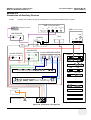
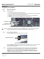
Connection of Auxiliary Devices . . . . . . . . . . . . . . . . . . . . . . . . . . . . . . . . . . . . . . .
Monitor Connection . . . . . . . . . . . . . . . . . . . . . . . . . . . . . . . . . . . . . . . . . . .
Foot Switch Connection . . . . . . . . . . . . . . . . . . . . . . . . . . . . . . . . . . . . . . .
ECG-preamplifier Connection . . . . . . . . . . . . . . . . . . . . . . . . . . . . . . . . . . .
Global Modem Connection . . . . . . . . . . . . . . . . . . . . . . . . . . . . . . . . . . . . .
S-VHS Video Recorder Connection . . . . . . . . . . . . . . . . . . . . . . . . . . . . . .
Mitsubishi HS-MD3000 . . . . . . . . . . . . . . . . . . . . . . . . . . . . . . . . . .
Sony SVO-9500MD . . . . . . . . . . . . . . . . . . . . . . . . . . . . . . . . . . . . .
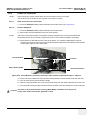
B/W Video Printer Connection . . . . . . . . . . . . . . . . . . . . . . . . . . . . . . . . . .
Line Printer Connection . . . . . . . . . . . . . . . . . . . . . . . . . . . . . . . . . . . . . . .
Digital Color Printer Connection . . . . . . . . . . . . . . . . . . . . . . . . . . . . . . . . .
Bluetooth Printer Connection . . . . . . . . . . . . . . . . . . . . . . . . . . . . . . . . . . .
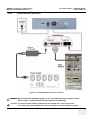
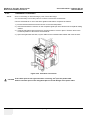
External USB-Devices . . . . . . . . . . . . . . . . . . . . . . . . . . . . . . . . . . . . . . . .
Connection . . . . . . . . . . . . . . . . . . . . . . . . . . . . . . . . . . . . . . . . . . . .
Disconnection . . . . . . . . . . . . . . . . . . . . . . . . . . . . . . . . . . . . . . . . .
3-7
3-9
3-9
3 - 10
3 - 11
3 - 12
3 - 12
3 - 13
3 - 14
3 - 15
3 - 16
3 - 17
3 - 18
3 - 18
3 - 18
Completing the Installation . . . . . . . . . . . . . . . . . . . . . . . . . . . . . . . . . . . . . . . . . . .
Power On / Boot Up . . . . . . . . . . . . . . . . . . . . . . . . . . . . . . . . . . . . . . . . . .
Scanner Power On . . . . . . . . . . . . . . . . . . . . . . . . . . . . . . . . . . . . . .
Back-end Processor Boot Up . . . . . . . . . . . . . . . . . . . . . . . . . . . . . .
Power Off/ Shutdown . . . . . . . . . . . . . . . . . . . . . . . . . . . . . . . . . . . . . . . . .
Back-end Processor Power Down . . . . . . . . . . . . . . . . . . . . . . . . . .
Scanner Shutdown . . . . . . . . . . . . . . . . . . . . . . . . . . . . . . . . . . . . . .
3 - 20
3 - 20
3 - 20
3 - 20
3 - 21
3 - 21
3 - 21
Table of Contents
xi
GE MEDICAL SYSTEMS - KRETZTECHNIK
DIRECTION KTI105947, REVISION 2
VOLUSON® 730PRO / 730PROV (BT´04)
SERVICE MANUAL
Transducer Connection . . . . . . . . . . . . . . . . . . . . . . . . . . . . . . . . . . . . . . . . 3 - 22
Printer Installation . . . . . . . . . . . . . . . . . . . . . . . . . . . . . . . . . . . . . . . . . . . . . . . . . . 3 - 23
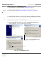
Installing Line Printer HP 990cxi or HP 995c . . . . . . . . . . . . . . . . . . . . . . . . 3 - 24
Install the HP 990cxi or HP 995c printer software/driver . . . . . . . . . . 3 - 24
Installing Digital Color Printer Sony UP-D21MD or UP-D23MD . . . . . . . . . . 3 - 26
Install the UP-D21MD / UP-D23MD printer software/driver . . . . . . . 3 - 26
Printer Installation manually . . . . . . . . . . . . . . . . . . . . . . . . . . . . . . . . . . . . . 3 - 28
Adjustment of Printer Settings . . . . . . . . . . . . . . . . . . . . . . . . . . . . . . . . . . . 3 - 33
HP 990cxi / HP 995c- Printer Settings . . . . . . . . . . . . . . . . . . . . . . . 3 - 34
UP-D21MD / UP-D23MD - Printer Settings . . . . . . . . . . . . . . . . . . . . 3 - 35
HP 5600 Series / Olivetti Job Jet 210 - Printer Settings . . . . . . . . . . 3 - 37
Printer Remote Control Selection . . . . . . . . . . . . . . . . . . . . . . . . . . . . . . . . . 3 - 38
System Configuration. . . . . . . . . . . . . . . . . . . . . . . . . . . . . . . . . . . . . . . . . . . . . . . . 3 - 39
System Specifications . . . . . . . . . . . . . . . . . . . . . . . . . . . . . . . . . . . . . . . . . 3 - 39
Physical Dimensions of Voluson® 730Pro / 730ProV . . . . . . . . . . . . 3 - 39
Weight without Monitor and Peripherals . . . . . . . . . . . . . . . . . . . . . . 3 - 39
Acoustic Noise Output . . . . . . . . . . . . . . . . . . . . . . . . . . . . . . . . . . . . 3 - 39
Electrical Specifications . . . . . . . . . . . . . . . . . . . . . . . . . . . . . . . . . . . . . . . . 3 - 39
System Setup . . . . . . . . . . . . . . . . . . . . . . . . . . . . . . . . . . . . . . . . . . . . . . . . 3 - 40
How to enter Date and Time . . . . . . . . . . . . . . . . . . . . . . . . . . . . . . . 3 - 41
How to enter Hospital Name . . . . . . . . . . . . . . . . . . . . . . . . . . . . . . . 3 - 41
How to change Language (and/or EUM Language) . . . . . . . . . . . . . 3 - 41
How to change Video Norm . . . . . . . . . . . . . . . . . . . . . . . . . . . . . . . 3 - 42
On-Board Optional Peripherals . . . . . . . . . . . . . . . . . . . . . . . . . . . . . . . . . . 3 - 43
External I/O Connection Panel (GES) . . . . . . . . . . . . . . . . . . . . . . . . . . . . . 3 - 44
External I/O Pin Outs . . . . . . . . . . . . . . . . . . . . . . . . . . . . . . . . . . . . . 3 - 45
Video Specification . . . . . . . . . . . . . . . . . . . . . . . . . . . . . . . . . . . . . . . . . . . . 3 - 46
Available Probes . . . . . . . . . . . . . . . . . . . . . . . . . . . . . . . . . . . . . . . . . . . . . . . . . . . 3 - 47
Software/Option Configuration. . . . . . . . . . . . . . . . . . . . . . . . . . . . . . . . . . . . . . . . . 3 - 48
Connectivity Installation Worksheet . . . . . . . . . . . . . . . . . . . . . . . . . . . . . . . . . . . . . 3 - 49
Network IP Address Configuration. . . . . . . . . . . . . . . . . . . . . . . . . . . . . . . . . . . . . . 3 - 50
Map Network Drive . . . . . . . . . . . . . . . . . . . . . . . . . . . . . . . . . . . . . . . . . . . . 3 - 51
Paperwork . . . . . . . . . . . . . . . . . . . . . . . . . . . . . . . . . . . . . . . . . . . . . . . . . . . . . . . . 3 - 52
Product Locator Installation . . . . . . . . . . . . . . . . . . . . . . . . . . . . . . . . . . . . . 3 - 52
User Manual(s) . . . . . . . . . . . . . . . . . . . . . . . . . . . . . . . . . . . . . . . . . . . . . . . 3 - 52
xii
Table of Contents
GE MEDICAL SYSTEMS - KRETZTECHNIK
DIRECTION KTI105947, REVISION 2
VOLUSON® 730PRO / 730PROV (BT´04)
SERVICE MANUAL
CHAPTER 4
Functional Checks
Overview . . . . . . . . . . . . . . . . . . . . . . . . . . . . . . . . . . . . . . . . . . . . . . . . . . . . . . . . 4 - 1
Purpose of Chapter 4 . . . . . . . . . . . . . . . . . . . . . . . . . . . . . . . . . . . . . . . . . 4 - 1
Required Equipment. . . . . . . . . . . . . . . . . . . . . . . . . . . . . . . . . . . . . . . . . . . . . . . . 4 - 1
General Procedure . . . . . . . . . . . . . . . . . . . . . . . . . . . . . . . . . . . . . . . . . . . . . . . . .
Power On / Boot Up . . . . . . . . . . . . . . . . . . . . . . . . . . . . . . . . . . . . . . . . . .
Scanner Power On . . . . . . . . . . . . . . . . . . . . . . . . . . . . . . . . . . . . . .
Power Off / Shutdown . . . . . . . . . . . . . . . . . . . . . . . . . . . . . . . . . . . . . . . .
Scanner Shutdown . . . . . . . . . . . . . . . . . . . . . . . . . . . . . . . . . . . . . .
System Features . . . . . . . . . . . . . . . . . . . . . . . . . . . . . . . . . . . . . . . . . . . . .
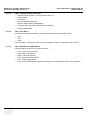
Control Panel . . . . . . . . . . . . . . . . . . . . . . . . . . . . . . . . . . . . . . . . .
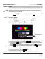
Menu Control . . . . . . . . . . . . . . . . . . . . . . . . . . . . . . . . . . . . . . . . . .
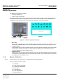
Monitor Display . . . . . . . . . . . . . . . . . . . . . . . . . . . . . . . . . . . . . . . .
4-2
4-2
4-2
4-3
4-3
4-4
4-4
4-5
4-6
Functional Checks . . . . . . . . . . . . . . . . . . . . . . . . . . . . . . . . . . . . . . . . . . . . . . . . .
2D Mode Checks . . . . . . . . . . . . . . . . . . . . . . . . . . . . . . . . . . . . . . . . . . . .
M Mode Checks . . . . . . . . . . . . . . . . . . . . . . . . . . . . . . . . . . . . . . . . . . . . .
MCFM Mode Check . . . . . . . . . . . . . . . . . . . . . . . . . . . . . . . . . . . .
Spectral Doppler Mode Checks . . . . . . . . . . . . . . . . . . . . . . . . . . . . . . . . .
Color Doppler Mode Checks . . . . . . . . . . . . . . . . . . . . . . . . . . . . . . . . . . .
Volume Mode Checks . . . . . . . . . . . . . . . . . . . . . . . . . . . . . . . . . . . . . . . .
Pre-Volume Mode Functions . . . . . . . . . . . . . . . . . . . . . . . . . . . . . .
Functions after the 3D Acquisition . . . . . . . . . . . . . . . . . . . . . . . . . .
Sub Menu . . . . . . . . . . . . . . . . . . . . . . . . . . . . . . . . . . . . . . . . . . . .
Using Cine . . . . . . . . . . . . . . . . . . . . . . . . . . . . . . . . . . . . . . . . . . . . . . . . .
Activating Cine . . . . . . . . . . . . . . . . . . . . . . . . . . . . . . . . . . . . . . . . .
Cine-Split Function (Multiple Format) . . . . . . . . . . . . . . . . . . . . . . .
Activating 2D Auto Cine . . . . . . . . . . . . . . . . . . . . . . . . . . . . . . . . . .
Spectral Doppler- or M Cine Loop . . . . . . . . . . . . . . . . . . . . . . . . . .
Activating 3D Rotation Cine . . . . . . . . . . . . . . . . . . . . . . . . . . . . . . .
Activating 4D Cine . . . . . . . . . . . . . . . . . . . . . . . . . . . . . . . . . . . . . .
Generic Measurements . . . . . . . . . . . . . . . . . . . . . . . . . . . . . . . . . . . . . . .
Distance and Tissue Depth Measurements (2D and M Mode) . . . .
Circumference/Area Measurements . . . . . . . . . . . . . . . . . . . . . . . .
Volume Measurements . . . . . . . . . . . . . . . . . . . . . . . . . . . . . . . . . .
Multiplane Measurements . . . . . . . . . . . . . . . . . . . . . . . . . . .
Measurements in Spectral Doppler Mode . . . . . . . . . . . . . . . . . . . .
Auto Trace . . . . . . . . . . . . . . . . . . . . . . . . . . . . . . . . . . . . . . .
Manual Trace . . . . . . . . . . . . . . . . . . . . . . . . . . . . . . . . . . . .
Heart Rate . . . . . . . . . . . . . . . . . . . . . . . . . . . . . . . . . . . . . . .
Calculations . . . . . . . . . . . . . . . . . . . . . . . . . . . . . . . . . . . . . . . . . . . . . . . .
4-7
4-8
4 - 11
4 - 12
4 - 13
4 - 15
4 - 17
4 - 17
4 - 18
4 - 20
4 - 21
4 - 21
4 - 21
4 - 21
4 - 21
4 - 21
4 - 21
4 - 22
4 - 22
4 - 23
4 - 23
4 - 23
4 - 24
4 - 24
4 - 24
4 - 24
4 - 25
Table of Contents
xiii
GE MEDICAL SYSTEMS - KRETZTECHNIK
DIRECTION KTI105947, REVISION 2
VOLUSON® 730PRO / 730PROV (BT´04)
SERVICE MANUAL
Worksheet (Report) Pages . . . . . . . . . . . . . . . . . . . . . . . . . . . . . . . . 4 - 25
Probe/Connectors Usage . . . . . . . . . . . . . . . . . . . . . . . . . . . . . . . . . . . . . . . 4 - 26
Connecting a probe . . . . . . . . . . . . . . . . . . . . . . . . . . . . . . . . . . . . . . 4 - 26
Activating the probe . . . . . . . . . . . . . . . . . . . . . . . . . . . . . . . . . . . . . . 4 - 26
Deactivating the probe . . . . . . . . . . . . . . . . . . . . . . . . . . . . . . . . . . . 4 - 26
Disconnecting the probe . . . . . . . . . . . . . . . . . . . . . . . . . . . . . . . . . . 4 - 26
Image Management (Sonoview) . . . . . . . . . . . . . . . . . . . . . . . . . . . . . . . . . 4 - 27
Using the MOD (Magneto-Optical Drive) . . . . . . . . . . . . . . . . . . . . . . . . . . . 4 - 28
Formatting Media . . . . . . . . . . . . . . . . . . . . . . . . . . . . . . . . . . . . . . . 4 - 29
Adjusting the Write Speed of the DVD/CD Recorder . . . . . . . 4 - 30
Backup and Restore Database, Preset Configurations and Images . . . . . . . . . . . . 4 - 31
Save User Settings Only (Application Settings) . . . . . . . . . . . . . . . . . . . . . . 4 - 32
Load User Settings Only (Application Settings) . . . . . . . . . . . . . . . . . . . . . . 4 - 33
Save Full Backup (Presets, Configurations & Application Settings) . . . . . . 4 - 35
Load Full Backup (Presets, Configurations & Application Settings) . . . . . . . 4 - 37
Delete Full Backup (Presets, Configurations & Application Settings) . . . . . 4 - 39
Archiving Images . . . . . . . . . . . . . . . . . . . . . . . . . . . . . . . . . . . . . . . . . . . . . 4 - 40
Software Configuration Checks . . . . . . . . . . . . . . . . . . . . . . . . . . . . . . . . . . . . . . . . 4 - 41
Peripheral Checks . . . . . . . . . . . . . . . . . . . . . . . . . . . . . . . . . . . . . . . . . . . . . . . . . . 4 - 42
ECG Check Out . . . . . . . . . . . . . . . . . . . . . . . . . . . . . . . . . . . . . . . . . . . . . 4 - 42
Power Supply Adjustment . . . . . . . . . . . . . . . . . . . . . . . . . . . . . . . . . . . . . . 4 - 42
Mechanical Function Checks . . . . . . . . . . . . . . . . . . . . . . . . . . . . . . . . . . . . . . . . . 4 - 43
Rotation of the Control Console . . . . . . . . . . . . . . . . . . . . . . . . . . . . . . . . . . 4 - 43
Brakes and Direction Locks . . . . . . . . . . . . . . . . . . . . . . . . . . . . . . . . . . . . . 4 - 43
Site Log . . . . . . . . . . . . . . . . . . . . . . . . . . . . . . . . . . . . . . . . . . . . . . . . . . . . . . . . . . 4 - 44
Site Log - System (Service Database) . . . . . . . . . . . . . . . . . . . . . . . . . . . . . 4 - 44
Site Log - Paper Documentation . . . . . . . . . . . . . . . . . . . . . . . . . . . . . . . . . 4 - 45
xiv
Table of Contents
GE MEDICAL SYSTEMS - KRETZTECHNIK
DIRECTION KTI105947, REVISION 2
VOLUSON® 730PRO / 730PROV (BT´04)
SERVICE MANUAL
CHAPTER 5
Components and Functions (Theory)
Overview. . . . . . . . . . . . . . . . . . . . . . . . . . . . . . . . . . . . . . . . . . . . . . . . . . . . . . . . . 5 - 1
Purpose of Chapter 5 . . . . . . . . . . . . . . . . . . . . . . . . . . . . . . . . . . . . . . . . . 5 - 1
General Information . . . . . . . . . . . . . . . . . . . . . . . . . . . . . . . . . . . . . . . . . . . . . . . .
Description of Voluson® 730Pro / 730ProV Operating Modes . . . . . . . . . .
B-Mode or 2D-Mode . . . . . . . . . . . . . . . . . . . . . . . . . . . . . . . . . . . .
Coded Harmonic Imaging (HI) . . . . . . . . . . . . . . . . . . . . . . .
M-Mode . . . . . . . . . . . . . . . . . . . . . . . . . . . . . . . . . . . . . . . . . . . . . .
MCFM Mode (M Mode + Color Flow Mode) . . . . . . . . . . . . .
Color Doppler Mode . . . . . . . . . . . . . . . . . . . . . . . . . . . . . . . . . . . . .
Color Flow Mode . . . . . . . . . . . . . . . . . . . . . . . . . . . . . . . . . .
Power Doppler . . . . . . . . . . . . . . . . . . . . . . . . . . . . . . . . . . .
Tissue Doppler . . . . . . . . . . . . . . . . . . . . . . . . . . . . . . . . . . .
Pulsed (PW) Doppler . . . . . . . . . . . . . . . . . . . . . . . . . . . . . . . . . . . .
3D Imaging . . . . . . . . . . . . . . . . . . . . . . . . . . . . . . . . . . . . . . . . . . . . . . . . .
3D Data Collection and Reconstruction . . . . . . . . . . . . . . . . . . . . . .
3D Image Presentation . . . . . . . . . . . . . . . . . . . . . . . . . . . . . . . . . .
3D Rendering . . . . . . . . . . . . . . . . . . . . . . . . . . . . . . . . . . . . . . . . . .
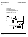
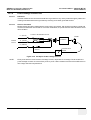
Block diagram Voluson® 730Pro / 730ProV . . . . . . . . . . . . . . . . . . . . . . . .
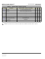
Dataflow Control Description . . . . . . . . . . . . . . . . . . . . . . . . . . . . . . . . . . .
B-Mode . . . . . . . . . . . . . . . . . . . . . . . . . . . . . . . . . . . . . . . . . . . . . .
Special B Mode Techniques . . . . . . . . . . . . . . . . . . . . . . . . .
M-Mode . . . . . . . . . . . . . . . . . . . . . . . . . . . . . . . . . . . . . . . . . . . . . .
D-Mode (Pulsed Wave- and Continuous Wave Doppler) . . . . . . . .
D-Mode Autotrace (draws PC-calculated envelope to D-Spectrum)
CFM-Mode (Color Flow Mode) . . . . . . . . . . . . . . . . . . . . . . . . . . . .
3D-Mode (Freezes after 1 volume sweep) . . . . . . . . . . . . . . . . . . . .
Real Time 4D-Mode (nonstop volume rendering) . . . . . . . . . . . . . .
XBeam CRI-Mode (CrossBeam Compound Resolution Imaging)* .
Extern-Video-Mode (display Video from Video-Recorder) . . . . . . . .
Sonoview write mode (store Image to Sonoview) . . . . . . . . . . . . . .
Description of Software Options . . . . . . . . . . . . . . . . . . . . . . . . . . . . . . . .
Real Time 4D . . . . . . . . . . . . . . . . . . . . . . . . . . . . . . . . . . . . . . . . . .
DICOM . . . . . . . . . . . . . . . . . . . . . . . . . . . . . . . . . . . . . . . . . . . . . . .
XBeam CRI - CrossBeam Compound Resolution Imaging* . . . . . .
VOCAL II - Virtual Organ Computer-aided Analysis* . . . . . . . . . . . .
Real Time 4D Biopsy* . . . . . . . . . . . . . . . . . . . . . . . . . . . . . . . . . . .
SRI - Speckle Reduction Imaging* . . . . . . . . . . . . . . . . . . . . . . . . . .
STIC (Spatio-Temporal Image Correlation)* . . . . . . . . . . . . . . . . . .
VCI - Volume Contrast Imaging* . . . . . . . . . . . . . . . . . . . . . . . . . . .
TUI - Tomographic Ultrasound Imaging* . . . . . . . . . . . . . . . . . . . . .
Description of Hardware Options . . . . . . . . . . . . . . . . . . . . . . . . . . . . . . . .
CW - Continuous Wave Doppler . . . . . . . . . . . . . . . . . . . . . . . . . . .
Table of Contents
5-2
5-6
5-6
5-6
5-6
5-6
5-7
5-7
5-7
5-7
5-7
5-8
5-8
5-8
5-8
5-9
5 - 11
5 - 11
5 - 12
5 - 12
5 - 13
5 - 13
5 - 14
5 - 14
5 - 14
5 - 14
5 - 14
5 - 15
5 - 15
5 - 15
5 - 16
5 - 16
5 - 16
5 - 16
5 - 16
5 - 17
5 - 17
5 - 17
5 - 18
5 - 18
xv
GE MEDICAL SYSTEMS - KRETZTECHNIK
DIRECTION KTI105947, REVISION 2
VOLUSON® 730PRO / 730PROV (BT´04)
SERVICE MANUAL
ECG Preamplifier . . . . . . . . . . . . . . . . . . . . . . . . . . . . . . . . . . . . . . . 5 - 18
MOD (Magneto-Optical Drive) . . . . . . . . . . . . . . . . . . . . . . . . . . . . . . 5 - 18
Scan/Freeze Foot switch . . . . . . . . . . . . . . . . . . . . . . . . . . . . . . . . . 5 - 18
Global Modem . . . . . . . . . . . . . . . . . . . . . . . . . . . . . . . . . . . . . . . . . . 5 - 18
Location in the Unit . . . . . . . . . . . . . . . . . . . . . . . . . . . . . . . . . 5 - 19
LEDs . . . . . . . . . . . . . . . . . . . . . . . . . . . . . . . . . . . . . . . . . . . . 5 - 19
Main board Chassis GEF Module . . . . . . . . . . . . . . . . . . . . . . . . . . . . . . . . . . . . . . 5 - 20
FrontEnd Processor . . . . . . . . . . . . . . . . . . . . . . . . . . . . . . . . . . . . . . . . . . . . . . . . . 5 - 21
FrontEnd - Board Descriptions . . . . . . . . . . . . . . . . . . . . . . . . . . . . . . . . . . . 5 - 22
CPU - Probe Connector Board . . . . . . . . . . . . . . . . . . . . . . . . . . . . . 5 - 22
CPR - Beamformer-Motherboard . . . . . . . . . . . . . . . . . . . . . . . . . . . 5 - 22
CPD-Beamformer-Sub-board . . . . . . . . . . . . . . . . . . . . . . . . . . . . . . 5 - 23
CRW - CW-Doppler Board (optional) . . . . . . . . . . . . . . . . . . . . . . . . 5 - 24
CPZ - Cover Board . . . . . . . . . . . . . . . . . . . . . . . . . . . . . . . . . . . . . . 5 - 24
CPK - Motherboard of GEF-Module . . . . . . . . . . . . . . . . . . . . . . . . . 5 - 24
CRS - Signal Processor Board . . . . . . . . . . . . . . . . . . . . . . . . . . . . . 5 - 25
CPP- Power Supply Secondary Board + Motor Power stage . . . . . . 5 - 25
BackEnd Processor . . . . . . . . . . . . . . . . . . . . . . . . . . . . . . . . . . . . . . . . . . . . . . . . 5 - 27
Block diagram CKV . . . . . . . . . . . . . . . . . . . . . . . . . . . . . . . . . . . . . . . . . . . 5 - 28
BackEnd - Board Descriptions . . . . . . . . . . . . . . . . . . . . . . . . . . . . . . . . . . 5 - 29
SBC - Single Board Computer . . . . . . . . . . . . . . . . . . . . . . . . . . . . . 5 - 29
PCI VGA Card . . . . . . . . . . . . . . . . . . . . . . . . . . . . . . . . . . . . . . . . . . 5 - 29
CKV - DMA-Controller / Video-Card . . . . . . . . . . . . . . . . . . . . . . . . . 5 - 29
Hard Disk Drive . . . . . . . . . . . . . . . . . . . . . . . . . . . . . . . . . . . . . . . . . 5 - 29
CPE - Back Panel I/O-Card . . . . . . . . . . . . . . . . . . . . . . . . . . . . . . . . 5 - 29
CPM - PC-Motherboard Card . . . . . . . . . . . . . . . . . . . . . . . . . . . . . . 5 - 29
CPP- Power Supply Secondary Board + Motor Power stage . . . . . . 5 - 30
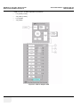
Internal I/O . . . . . . . . . . . . . . . . . . . . . . . . . . . . . . . . . . . . . . . . . . . . . . . . . . . . . . . . 5 - 31
Top Console. . . . . . . . . . . . . . . . . . . . . . . . . . . . . . . . . . . . . . . . . . . . . . . . . . . . . . . 5 - 34
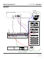
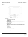
Monitor . . . . . . . . . . . . . . . . . . . . . . . . . . . . . . . . . . . . . . . . . . . . . . . . . . . . . . . . . . . 5 - 39
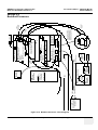
External I/O . . . . . . . . . . . . . . . . . . . . . . . . . . . . . . . . . . . . . . . . . . . . . . . . . . . . . . . 5 - 40
Peripherals. . . . . . . . . . . . . . . . . . . . . . . . . . . . . . . . . . . . . . . . . . . . . . . . . . . . . . . . 5 - 41
General Information . . . . . . . . . . . . . . . . . . . . . . . . . . . . . . . . . . . . . . . . . . . 5 - 41
ECG-preamplifier (MAN6 - optional) . . . . . . . . . . . . . . . . . . . . . . . . . 5 - 41
DVD/CD+(R)W Drive . . . . . . . . . . . . . . . . . . . . . . . . . . . . . . . . . . . . . 5 - 41
Magneto-Optical Drive (optional) . . . . . . . . . . . . . . . . . . . . . . . . . . . . 5 - 41
Power Distribution . . . . . . . . . . . . . . . . . . . . . . . . . . . . . . . . . . . . . . . . . . . . . . . . . . 5 - 42
CPN6 - Primary Power Module . . . . . . . . . . . . . . . . . . . . . . . . . . . . . . . . . . 5 - 42
xvi
Table of Contents
GE MEDICAL SYSTEMS - KRETZTECHNIK
DIRECTION KTI105947, REVISION 2
VOLUSON® 730PRO / 730PROV (BT´04)
SERVICE MANUAL
Mechanical Concept and Overview . . . . . . . . . . . . . . . . . . . . . . . . .
Major Functions of CPN6 . . . . . . . . . . . . . . . . . . . . . . . . . . . . . . . . .
Fuses on Rear Panel (CPN6) . . . . . . . . . . . . . . . . . . . . . . . . . . . . .
Fuses inside CPN6 . . . . . . . . . . . . . . . . . . . . . . . . . . . . . . . . . . . . .
CPN80 - Primary Power Module . . . . . . . . . . . . . . . . . . . . . . . . . . . . . . . . .
Mechanical Concept and Overview . . . . . . . . . . . . . . . . . . . . . . . . .
Major Functions of CPN80 . . . . . . . . . . . . . . . . . . . . . . . . . . . . . . . .
Fuses on Rear Panel (CPN80) . . . . . . . . . . . . . . . . . . . . . . . . . . . .
Fuses inside CPN80 . . . . . . . . . . . . . . . . . . . . . . . . . . . . . . . . . . . .
Disk Drive Module (GEM) . . . . . . . . . . . . . . . . . . . . . . . . . . . . . . . . . . . . . .
Fuses on CPE-Board for Disk Drive Module (GEM) . . . . . . . . . . . .
5 - 42
5 - 42
5 - 43
5 - 43
5 - 44
5 - 44
5 - 44
5 - 45
5 - 45
5 - 45
5 - 45
Mechanical Descriptions. . . . . . . . . . . . . . . . . . . . . . . . . . . . . . . . . . . . . . . . . . . . .
Physical Dimensions . . . . . . . . . . . . . . . . . . . . . . . . . . . . . . . . . . . . . . . . . .
Monitor . . . . . . . . . . . . . . . . . . . . . . . . . . . . . . . . . . . . . . . . . . . . . . . . . . . .
Top Console Positioning . . . . . . . . . . . . . . . . . . . . . . . . . . . . . . . . . . . . . . .
Rotation of the Control Console . . . . . . . . . . . . . . . . . . . . . . . . . . . . . . . . .
Assembly Drawing GW & GEU & Monitor . . . . . . . . . . . . . . . . . . . . . . . . .
5 - 46
5 - 46
5 - 47
5 - 47
5 - 47
5 - 48
Air Flow Control . . . . . . . . . . . . . . . . . . . . . . . . . . . . . . . . . . . . . . . . . . . . . . . . . . . 5 - 49
Air Flow Distribution . . . . . . . . . . . . . . . . . . . . . . . . . . . . . . . . . . . . . . . . . . 5 - 49
Air Flow Distribution Overview . . . . . . . . . . . . . . . . . . . . . . . . . . . . 5 - 49
Service Platform . . . . . . . . . . . . . . . . . . . . . . . . . . . . . . . . . . . . . . . . . . . . . . . . . . .
Introduction . . . . . . . . . . . . . . . . . . . . . . . . . . . . . . . . . . . . . . . . . . . . . . . . .
Access / Security . . . . . . . . . . . . . . . . . . . . . . . . . . . . . . . . . . . . . . . . . . . .
iLinq Interactive Platform . . . . . . . . . . . . . . . . . . . . . . . . . . . . . . . . . . . . . .
5 - 50
5 - 50
5 - 50
5 - 51
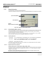
Service Page . . . . . . . . . . . . . . . . . . . . . . . . . . . . . . . . . . . . . . . . . . . . . . . . . . . . .
Introduction . . . . . . . . . . . . . . . . . . . . . . . . . . . . . . . . . . . . . . . . . . . . . . . . .
Access / Security . . . . . . . . . . . . . . . . . . . . . . . . . . . . . . . . . . . . . . . . . . . .
Service Login . . . . . . . . . . . . . . . . . . . . . . . . . . . . . . . . . . . . . . . . . . . . . . .
Video Norm . . . . . . . . . . . . . . . . . . . . . . . . . . . . . . . . . . . . . . . . . . .
Auto Tester File . . . . . . . . . . . . . . . . . . . . . . . . . . . . . . . . . . . . . . . .
Service Viewer . . . . . . . . . . . . . . . . . . . . . . . . . . . . . . . . . . . . . . . . .
Delete all Patients . . . . . . . . . . . . . . . . . . . . . . . . . . . . . . . . . . . . . .
Export System Data . . . . . . . . . . . . . . . . . . . . . . . . . . . . . . . . . . . . .
Maintenance Report . . . . . . . . . . . . . . . . . . . . . . . . . . . . . . . . . . . . .
Monitor Test . . . . . . . . . . . . . . . . . . . . . . . . . . . . . . . . . . . . . . . . . . .
Printer . . . . . . . . . . . . . . . . . . . . . . . . . . . . . . . . . . . . . . . . . . . . . . .
Update . . . . . . . . . . . . . . . . . . . . . . . . . . . . . . . . . . . . . . . . . . . . . . .
NLS . . . . . . . . . . . . . . . . . . . . . . . . . . . . . . . . . . . . . . . . . . . .
EUM . . . . . . . . . . . . . . . . . . . . . . . . . . . . . . . . . . . . . . . . . . .
UIS . . . . . . . . . . . . . . . . . . . . . . . . . . . . . . . . . . . . . . . . . . . .
SSW . . . . . . . . . . . . . . . . . . . . . . . . . . . . . . . . . . . . . . . . . . .
5 - 52
5 - 52
5 - 52
5 - 52
5 - 53
5 - 53
5 - 54
5 - 54
5 - 54
5 - 54
5 - 55
5 - 56
5 - 56
5 - 56
5 - 56
5 - 56
5 - 56
Table of Contents
xvii
GE MEDICAL SYSTEMS - KRETZTECHNIK
DIRECTION KTI105947, REVISION 2
VOLUSON® 730PRO / 730PROV (BT´04)
SERVICE MANUAL
CHAPTER 6
Service Adjustments
Overview . . . . . . . . . . . . . . . . . . . . . . . . . . . . . . . . . . . . . . . . . . . . . . . . . . . . . . . . . 6 - 1
Purpose of Chapter 6 . . . . . . . . . . . . . . . . . . . . . . . . . . . . . . . . . . . . . . . . . . 6 - 1
Regulatory . . . . . . . . . . . . . . . . . . . . . . . . . . . . . . . . . . . . . . . . . . . . . . . . . . . . . . . . 6 - 1
Monitor Adjustment . . . . . . . . . . . . . . . . . . . . . . . . . . . . . . . . . . . . . . . . . . . . . . . . . 6 - 2
Monitor Calibration . . . . . . . . . . . . . . . . . . . . . . . . . . . . . . . . . . . . . . . . . . . . 6 - 2
Degauss . . . . . . . . . . . . . . . . . . . . . . . . . . . . . . . . . . . . . . . . . . . . . . 6 - 3
Color Temp - Calibration . . . . . . . . . . . . . . . . . . . . . . . . . . . . . . . . . . 6 - 3
Contrast and Brightness . . . . . . . . . . . . . . . . . . . . . . . . . . . . . . . . . . 6 - 4
Geometry . . . . . . . . . . . . . . . . . . . . . . . . . . . . . . . . . . . . . . . . . . . . . . 6 - 4
Convergence . . . . . . . . . . . . . . . . . . . . . . . . . . . . . . . . . . . . . . . . . . . 6 - 4
Color temperature . . . . . . . . . . . . . . . . . . . . . . . . . . . . . . . . . . . . . . . 6 - 4
B-Mode Quality . . . . . . . . . . . . . . . . . . . . . . . . . . . . . . . . . . . . . . . . . 6 - 4
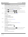
Control Console, Transport Lock . . . . . . . . . . . . . . . . . . . . . . . . . . . . . . . . . . . . . . . 6 - 5
Control Console . . . . . . . . . . . . . . . . . . . . . . . . . . . . . . . . . . . . . . . . . . . . . . 6 - 5
Transport Lock . . . . . . . . . . . . . . . . . . . . . . . . . . . . . . . . . . . . . . . . . . . . . . . 6 - 5
Trackball Adjustment . . . . . . . . . . . . . . . . . . . . . . . . . . . . . . . . . . . . . . . . . . . . . . . . 6 - 6
xviii
Table of Contents
GE MEDICAL SYSTEMS - KRETZTECHNIK
DIRECTION KTI105947, REVISION 2
VOLUSON® 730PRO / 730PROV (BT´04)
SERVICE MANUAL
CHAPTER 7
Diagnostics/Troubleshooting
Overview. . . . . . . . . . . . . . . . . . . . . . . . . . . . . . . . . . . . . . . . . . . . . . . . . . . . . . . . . 7 - 1
Purpose of Chapter 7 . . . . . . . . . . . . . . . . . . . . . . . . . . . . . . . . . . . . . . . . . 7 - 1
Overview . . . . . . . . . . . . . . . . . . . . . . . . . . . . . . . . . . . . . . . . . . . . . . . . . . . 7 - 1
Collect Vital System Information. . . . . . . . . . . . . . . . . . . . . . . . . . . . . . . . . . . . . . . 7 - 2
Needed Data - in case of System crash or Errors . . . . . . . . . . . . . . . . . . . 7 - 3
Check Points Voltages . . . . . . . . . . . . . . . . . . . . . . . . . . . . . . . . . . . . . . . . . . . . . . 7 - 4
How to check power . . . . . . . . . . . . . . . . . . . . . . . . . . . . . . . . . . . . . . . . . 7 - 4
Screen Captures and Logs. . . . . . . . . . . . . . . . . . . . . . . . . . . . . . . . . . . . . . . . . . .
Capturing a screen . . . . . . . . . . . . . . . . . . . . . . . . . . . . . . . . . . . . . . . . . . .
Export Log’s and System Data . . . . . . . . . . . . . . . . . . . . . . . . . . . . . . . . . .
Export System Data (by pressing the ALT + D key) . . . . . . . . . . . .
Export Log´s and System Data (via Service Page) . . . . . . . . . . . . .
Dump-file . . . . . . . . . . . . . . . . . . . . . . . . . . . . . . . . . . . . . . . .
7-5
7-5
7-5
7-6
7-7
7-7
How to use the Auto Tester program . . . . . . . . . . . . . . . . . . . . . . . . . . . . . . . . . . . 7 - 8
Minimum Configuration to Boot/Scan . . . . . . . . . . . . . . . . . . . . . . . . . . . . . . . . . . . 7 - 11
Booting without using the Ultrasound Hardware . . . . . . . . . . . . . . . . . . . . . 7 - 11
Minimum Configuration to Scan . . . . . . . . . . . . . . . . . . . . . . . . . . . . . . . . . 7 - 12
Troubleshooting Trees and Instructions . . . . . . . . . . . . . . . . . . . . . . . . . . . . . . . . .
System Does Not Power On / Boot Up . . . . . . . . . . . . . . . . . . . . . . . . . . . .
Noise disturbs the Image . . . . . . . . . . . . . . . . . . . . . . . . . . . . . . . . . . . . . .
Trackball . . . . . . . . . . . . . . . . . . . . . . . . . . . . . . . . . . . . . . . . . . . . . . . . . . .
System Does Not Power Off / Shutdown . . . . . . . . . . . . . . . . . . . . . . . . . .
Monitor Troubleshooting . . . . . . . . . . . . . . . . . . . . . . . . . . . . . . . . . . . . . . .
Unable to Record to VCR . . . . . . . . . . . . . . . . . . . . . . . . . . . . . . . . . . . . . .
Printer Troubleshooting . . . . . . . . . . . . . . . . . . . . . . . . . . . . . . . . . . . . . . .
DVD/CD+(R)W Troubleshooting (DVD/CD Drive) . . . . . . . . . . . . . . . . . . .
MOD Troubleshooting . . . . . . . . . . . . . . . . . . . . . . . . . . . . . . . . . . . . . . . . .
Network Troubleshooting . . . . . . . . . . . . . . . . . . . . . . . . . . . . . . . . . . . . . .
No Connection to the Network at All . . . . . . . . . . . . . . . . . . . . . . . .
GE remote service connection . . . . . . . . . . . . . . . . . . . . . . . . . . . . .
7 - 13
7 - 13
7 - 14
7 - 15
7 - 16
7 - 17
7 - 18
7 - 19
7 - 21
7 - 21
7 - 22
7 - 22
7 - 22
Error Messages . . . . . . . . . . . . . . . . . . . . . . . . . . . . . . . . . . . . . . . . . . . . . . . . . . . 7 - 23
Table of Contents
xix
GE MEDICAL SYSTEMS - KRETZTECHNIK
DIRECTION KTI105947, REVISION 2
VOLUSON® 730PRO / 730PROV (BT´04)
SERVICE MANUAL
CHAPTER 8
Replacement Procedures
Overview . . . . . . . . . . . . . . . . . . . . . . . . . . . . . . . . . . . . . . . . . . . . . . . . . . . . . . . . . 8 - 1
Purpose of Chapter 8 . . . . . . . . . . . . . . . . . . . . . . . . . . . . . . . . . . . . . . . . . . 8 - 1
Returning/Shipping Probes and Repair Parts . . . . . . . . . . . . . . . . . . . . . . . 8 - 2
Ultrasound Application Software (UIS) Installation Procedure. . . . . . . . . . . . . . . . . 8 - 2
Introduction . . . . . . . . . . . . . . . . . . . . . . . . . . . . . . . . . . . . . . . . . . . . . . . . . 8 - 2
Manpower . . . . . . . . . . . . . . . . . . . . . . . . . . . . . . . . . . . . . . . . . . . . . . . . . . 8 - 2
Tools . . . . . . . . . . . . . . . . . . . . . . . . . . . . . . . . . . . . . . . . . . . . . . . . . . . . . . 8 - 2
Preparations . . . . . . . . . . . . . . . . . . . . . . . . . . . . . . . . . . . . . . . . . . . . . . . . . 8 - 2
Software - Installation Procedure (via Service Page) . . . . . . . . . . . . . . . . . . 8 - 5
User Settings Only (Application Settings) Loading Procedure. . . . . . . . . . . . . . . . . 8 - 8
Introduction . . . . . . . . . . . . . . . . . . . . . . . . . . . . . . . . . . . . . . . . . . . . . . . . . 8 - 8
Loading Procedure . . . . . . . . . . . . . . . . . . . . . . . . . . . . . . . . . . . . . . . . . . . . 8 - 8
Full Backup (Presets, Configurations & Appl. Settings) Loading Procedure . . . . . . 8 - 8
Introduction . . . . . . . . . . . . . . . . . . . . . . . . . . . . . . . . . . . . . . . . . . . . . . . . . 8 - 8
Loading Procedure . . . . . . . . . . . . . . . . . . . . . . . . . . . . . . . . . . . . . . . . . . . . 8 - 8
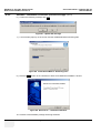
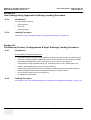
Service Platform (SSW) Upgrade Procedure. . . . . . . . . . . . . . . . . . . . . . . . . . . . . . 8 - 9
Manpower . . . . . . . . . . . . . . . . . . . . . . . . . . . . . . . . . . . . . . . . . . . . . . . . . . 8 - 9
Tools . . . . . . . . . . . . . . . . . . . . . . . . . . . . . . . . . . . . . . . . . . . . . . . . . . . . . . 8 - 9
Upgrade Procedure . . . . . . . . . . . . . . . . . . . . . . . . . . . . . . . . . . . . . . . . . . . 8 - 9
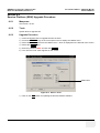
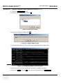
Electronic User Manual (EUM) Upgrade Procedure . . . . . . . . . . . . . . . . . . . . . . . . 8 - 11
Manpower . . . . . . . . . . . . . . . . . . . . . . . . . . . . . . . . . . . . . . . . . . . . . . . . . . 8 - 11
Tools . . . . . . . . . . . . . . . . . . . . . . . . . . . . . . . . . . . . . . . . . . . . . . . . . . . . . . 8 - 11
Preparations . . . . . . . . . . . . . . . . . . . . . . . . . . . . . . . . . . . . . . . . . . . . . . . . . 8 - 11
EUM - Upgrade Procedure . . . . . . . . . . . . . . . . . . . . . . . . . . . . . . . . . . . . . . 8 - 12
Software and Functional Checks after the Upgrade . . . . . . . . . . . . . . . . . . . . . . . . 8 - 14
Replacement or Activation of Options . . . . . . . . . . . . . . . . . . . . . . . . . . . . . . . . . . . 8 - 15
Operation for activating Options . . . . . . . . . . . . . . . . . . . . . . . . . . . . . . . . . . 8 - 15
Operation for installing a “Demo Key” or a “Permanent Key”: . . . . . . 8 - 16
Transfer of Patient Database and Images from System-to-System. . . . . . . . . . . . . 8 - 17
Introduction . . . . . . . . . . . . . . . . . . . . . . . . . . . . . . . . . . . . . . . . . . . . . . . . . 8 - 17
Transfer of Patient Database and Images via Sonoview . . . . . . . . . . . . . . . 8 - 18
Introduction . . . . . . . . . . . . . . . . . . . . . . . . . . . . . . . . . . . . . . . . . . . . 8 - 18
Manpower . . . . . . . . . . . . . . . . . . . . . . . . . . . . . . . . . . . . . . . . . . . . . 8 - 18
xx
Table of Contents
GE MEDICAL SYSTEMS - KRETZTECHNIK
DIRECTION KTI105947, REVISION 2
VOLUSON® 730PRO / 730PROV (BT´04)
SERVICE MANUAL
Tools . . . . . . . . . . . . . . . . . . . . . . . . . . . . . . . . . . . . . . . . . . . . . . . . 8 - 18
Backup all Exams of the “old” system . . . . . . . . . . . . . . . . . . . . . . . 8 - 18
Restore all Exams (of the “old” system) to the “new” system . . . . . 8 - 19
Replacement of the Monitor Task Lamp. . . . . . . . . . . . . . . . . . . . . . . . . . . . . . . . .
Manpower . . . . . . . . . . . . . . . . . . . . . . . . . . . . . . . . . . . . . . . . . . . . . . . . . .
Tools . . . . . . . . . . . . . . . . . . . . . . . . . . . . . . . . . . . . . . . . . . . . . . . . . . . . . .
Preparations . . . . . . . . . . . . . . . . . . . . . . . . . . . . . . . . . . . . . . . . . . . . . . . .
Task Lamp - Removal Procedure . . . . . . . . . . . . . . . . . . . . . . . . . . . . . . . .
Task Lamp - Installation Procedure . . . . . . . . . . . . . . . . . . . . . . . . . . . . . .
8 - 22
8 - 22
8 - 22
8 - 22
8 - 22
8 - 22
Replacement of the Trackball top fixation ring . . . . . . . . . . . . . . . . . . . . . . . . . . . . 8 - 23
Manpower . . . . . . . . . . . . . . . . . . . . . . . . . . . . . . . . . . . . . . . . . . . . . . . . . . 8 - 23
Trackball top fixation ring - Replacement Procedure . . . . . . . . . . . . . . . . . 8 - 23
Replacement of Digipots and TGC Slider controls . . . . . . . . . . . . . . . . . . . . . . . . .
Manpower . . . . . . . . . . . . . . . . . . . . . . . . . . . . . . . . . . . . . . . . . . . . . . . . . .
Tools . . . . . . . . . . . . . . . . . . . . . . . . . . . . . . . . . . . . . . . . . . . . . . . . . . . . . .
Cap and/or Spring - Replacement Procedure . . . . . . . . . . . . . . . . . . . . . . .
Table of Contents
8 - 23
8 - 23
8 - 23
8 - 23
xxi
GE MEDICAL SYSTEMS - KRETZTECHNIK
DIRECTION KTI105947, REVISION 2
VOLUSON® 730PRO / 730PROV (BT´04)
SERVICE MANUAL
CHAPTER 9
Renewal Parts
Overview . . . . . . . . . . . . . . . . . . . . . . . . . . . . . . . . . . . . . . . . . . . . . . . . . . . . . . . . . 9 - 1
Purpose of Chapter 9 . . . . . . . . . . . . . . . . . . . . . . . . . . . . . . . . . . . . . . . . . . 9 - 1
List of Abbreviations. . . . . . . . . . . . . . . . . . . . . . . . . . . . . . . . . . . . . . . . . . . . . . . . . 9 - 2
Parts List Groups . . . . . . . . . . . . . . . . . . . . . . . . . . . . . . . . . . . . . . . . . . . . . . . . . . 9 - 3
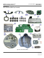
Housing (GW) and additional Console Hardware . . . . . . . . . . . . . . . . . . . . . . . . . . 9 - 4
User Interface (GEU Top Console) . . . . . . . . . . . . . . . . . . . . . . . . . . . . . . . . . . . . . 9 - 7
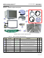
Monitor + Monitor replacement parts . . . . . . . . . . . . . . . . . . . . . . . . . . . . . . . . . . . . 9 - 9
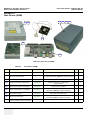
Disk Drives (GEM) . . . . . . . . . . . . . . . . . . . . . . . . . . . . . . . . . . . . . . . . . . . . . . . . . . 9 - 10
Main Power Module (CPN) . . . . . . . . . . . . . . . . . . . . . . . . . . . . . . . . . . . . . . . . . . . 9 - 11
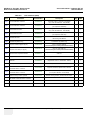
Main Board Module (GEF) . . . . . . . . . . . . . . . . . . . . . . . . . . . . . . . . . . . . . . . . . . . . 9 - 13
FrontEnd (US-Part) . . . . . . . . . . . . . . . . . . . . . . . . . . . . . . . . . . . . . . . . . . . 9 - 14
BackEnd Processor (PC-Part) . . . . . . . . . . . . . . . . . . . . . . . . . . . . . . . . . . . 9 - 16
Options and Upgrades . . . . . . . . . . . . . . . . . . . . . . . . . . . . . . . . . . . . . . . . . . . . . . . 9 - 18
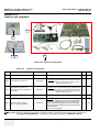
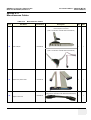
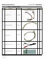
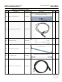
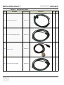
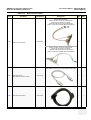
Miscellaneous Cables . . . . . . . . . . . . . . . . . . . . . . . . . . . . . . . . . . . . . . . . . . . . . . . 9 - 19
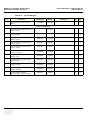
Optional Peripherals and Accessories . . . . . . . . . . . . . . . . . . . . . . . . . . . . . . . . . . . 9 - 25
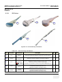
Probes . . . . . . . . . . . . . . . . . . . . . . . . . . . . . . . . . . . . . . . . . . . . . . . . . . . . . . . . . . . 9 - 29
2D-Probes . . . . . . . . . . . . . . . . . . . . . . . . . . . . . . . . . . . . . . . . . . . . . . . . . . 9 - 29
9-13-1 . . . . . . . . . . . . . . . . . . . . . . . . . . . . . . . . . . . . . . . . . . . . . . . . . . . . . .2DProbes (cont’d) . . . . . . . . . . . . . . . . . . . . . . . . . . . . . . . . . . . . . . . . . . . . . . . . . . . . . . . . . . 9 - 30
Real-Time 4D Volume Probes . . . . . . . . . . . . . . . . . . . . . . . . . . . . . . . . . . . 9 - 31
CW-Pencil Probes . . . . . . . . . . . . . . . . . . . . . . . . . . . . . . . . . . . . . . . . . . . . 9 - 33
Biopsy Needle Guides . . . . . . . . . . . . . . . . . . . . . . . . . . . . . . . . . . . . . . . . . . . . . . 9 - 34
xxii
Table of Contents
GE MEDICAL SYSTEMS - KRETZTECHNIK
DIRECTION KTI105947, REVISION 2
VOLUSON® 730PRO / 730PROV (BT´04)
SERVICE MANUAL
CHAPTER 10
Care & Maintenance
Overview. . . . . . . . . . . . . . . . . . . . . . . . . . . . . . . . . . . . . . . . . . . . . . . . . . . . . . . . . 10 - 1
Periodic Maintenance Inspections . . . . . . . . . . . . . . . . . . . . . . . . . . . . . . . 10 - 1
Purpose of Chapter 10 . . . . . . . . . . . . . . . . . . . . . . . . . . . . . . . . . . . . . . . . 10 - 1
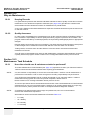
Why do Maintenance . . . . . . . . . . . . . . . . . . . . . . . . . . . . . . . . . . . . . . . . . . . . . . . 10 - 2
Keeping Records . . . . . . . . . . . . . . . . . . . . . . . . . . . . . . . . . . . . . . . . . . . . 10 - 2
Quality Assurance . . . . . . . . . . . . . . . . . . . . . . . . . . . . . . . . . . . . . . . . . . . . 10 - 2
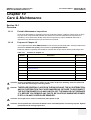
Maintenance Task Schedule . . . . . . . . . . . . . . . . . . . . . . . . . . . . . . . . . . . . . . . . . 10 - 2
How often should care & maintenance tasks be performed? . . . . . . . . . . . 10 - 2
Tools Required . . . . . . . . . . . . . . . . . . . . . . . . . . . . . . . . . . . . . . . . . . . . . . . . . . . . 10 - 5
Special Tools, Supplies and Equipment . . . . . . . . . . . . . . . . . . . . . . . . . . . 10 - 5
Specific Requirements for Care & Maintenance . . . . . . . . . . . . . . . 10 - 5
System Maintenance . . . . . . . . . . . . . . . . . . . . . . . . . . . . . . . . . . . . . . . . . . . . . . .
Preliminary Checks . . . . . . . . . . . . . . . . . . . . . . . . . . . . . . . . . . . . . . . . . . .
Functional Checks (see also Chapter 4) . . . . . . . . . . . . . . . . . . . . . . . . . . .
System Checks . . . . . . . . . . . . . . . . . . . . . . . . . . . . . . . . . . . . . . . .
Peripheral/Option Checks . . . . . . . . . . . . . . . . . . . . . . . . . . . . . . . .
Input Power . . . . . . . . . . . . . . . . . . . . . . . . . . . . . . . . . . . . . . . . . . . . . . . . .
Mains Cable Inspection . . . . . . . . . . . . . . . . . . . . . . . . . . . . . . . . . .
Cleaning . . . . . . . . . . . . . . . . . . . . . . . . . . . . . . . . . . . . . . . . . . . . . . . . . . .
General Cleaning . . . . . . . . . . . . . . . . . . . . . . . . . . . . . . . . . . . . . . .
Physical Inspection . . . . . . . . . . . . . . . . . . . . . . . . . . . . . . . . . . . . . . . . . . .
Optional Diagnostic Checks . . . . . . . . . . . . . . . . . . . . . . . . . . . . . . . . . . . .
Probe Maintenance . . . . . . . . . . . . . . . . . . . . . . . . . . . . . . . . . . . . . . . . . . .
Probe Related Checks . . . . . . . . . . . . . . . . . . . . . . . . . . . . . . . . . . .
Basic Probe Care . . . . . . . . . . . . . . . . . . . . . . . . . . . . . . . . . . . . . . .
Basic Probe Cleaning . . . . . . . . . . . . . . . . . . . . . . . . . . . . . . . . . . .
10 - 6
10 - 6
10 - 7
10 - 7
10 - 8
10 - 8
10 - 8
10 - 8
10 - 8
10 - 9
10 - 10
10 - 10
10 - 10
10 - 10
10 - 10
Using a Phantom . . . . . . . . . . . . . . . . . . . . . . . . . . . . . . . . . . . . . . . . . . . . . . . . . . 10 - 11
Electrical Safety Tests . . . . . . . . . . . . . . . . . . . . . . . . . . . . . . . . . . . . . . . . . . . . . .
Safety Test Overview . . . . . . . . . . . . . . . . . . . . . . . . . . . . . . . . . . . . . . . . .
GEMS Leakage Current Limits . . . . . . . . . . . . . . . . . . . . . . . . . . . . . . . . . .
Outlet Test - Wiring Arrangement - USA & Canada . . . . . . . . . . . . . . . . . .
Grounding Continuity . . . . . . . . . . . . . . . . . . . . . . . . . . . . . . . . . . . . . . . . .
Meter Procedure . . . . . . . . . . . . . . . . . . . . . . . . . . . . . . . . . . . . . . .
Chassis Leakage Current Test . . . . . . . . . . . . . . . . . . . . . . . . . . . . . . . . . .
Definition . . . . . . . . . . . . . . . . . . . . . . . . . . . . . . . . . . . . . . . . . . . . .
Table of Contents
10 - 11
10 - 11
10 - 12
10 - 13
10 - 14
10 - 14
10 - 15
10 - 15
xxiii
GE MEDICAL SYSTEMS - KRETZTECHNIK
DIRECTION KTI105947, REVISION 2
VOLUSON® 730PRO / 730PROV (BT´04)
SERVICE MANUAL
Generic Procedure . . . . . . . . . . . . . . . . . . . . . . . . . . . . . . . . . . . . . . 10 - 15
Data Sheet for Chassis Source Leakage Current . . . . . . . . . . . . . . . 10 - 17
Isolated Patient Lead (Source) Leakage–Lead to Ground . . . . . . . . . . . . . . 10 - 17
Definition . . . . . . . . . . . . . . . . . . . . . . . . . . . . . . . . . . . . . . . . . . . . . . 10 - 17
Generic Procedure . . . . . . . . . . . . . . . . . . . . . . . . . . . . . . . . . . . . . . 10 - 18
Isolated Patient Lead (Source) Leakage–Lead to Lead . . . . . . . . . . . . . . . . 10 - 18
Isolated Patient Lead (Sink) Leakage-Isolation Test . . . . . . . . . . . . . . . . . . 10 - 19
Data Sheet for ECG Leakage Current . . . . . . . . . . . . . . . . . . . . . . . . 10 - 20
Probe Leakage Current Test . . . . . . . . . . . . . . . . . . . . . . . . . . . . . . . . . . . . 10 - 21
Definition . . . . . . . . . . . . . . . . . . . . . . . . . . . . . . . . . . . . . . . . . . . . . . 10 - 21
Generic Procedure . . . . . . . . . . . . . . . . . . . . . . . . . . . . . . . . . . . . . . 10 - 21
No Meter Probe Adapter Procedure . . . . . . . . . . . . . . . . . . . . . . . . . 10 - 22
Data Sheet for Transducer Source Leakage Current . . . . . . . . . . . . 10 - 23
When There's Too Much Leakage Current... . . . . . . . . . . . . . . . . . . . . . . . . . . . . . . 10 - 24
xxiv
Table of Contents
GE MEDICAL SYSTEMS - KRETZTECHNIK
DIRECTION KTI105947, REVISION 2
DRAFT
VOLUSON® 730PRO / 730PROV (BT´04)
SERVICE MANUAL
Chapter 1
Introduction
Section 1-1
Overview
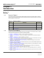
1-1-1
Purpose of Chapter 1
This chapter describes important issues related to safely servicing the Voluson® 730Pro / 730ProV
scanner. The service provider must read and understand all the information presented in this manual
before installing or servicing a unit.
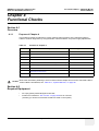
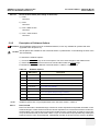
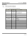
Table 1-1
Contents in Chapter 1
Section
1-1-2
Description
Page Number
1-1
Overview
1-1
1-2
Important Conventions
1-3
1-3
Safety Considerations
1-7
1-4
Electromagnetic Compatibility (EMC)
1-10
1-5
Customer Assistance
1-11
Purpose of Service Manual
This Service Manual provides installation and service information for the Voluson® 730Pro / 730ProV
Ultrasound Scanning System and contains the following chapters:
1.) Chapter 1 - Introduction: Contains a content summary and warnings.
2.) Chapter 2 - Pre-Installation: Contains pre-installation requirements for the Voluson® 730Pro /
730ProV.
3.) Chapter 3 - Installation: Contains installation procedures.
4.) Chapter 4 - Functional Checks: Contains functional checks that are recommended as part of the
installation, or as required during servicing and periodic maintenance.
5.) Chapter 5 - Components and Functions (Theory): Contains block diagrams and functional
explanations of the electronics.
6.) Chapter 6 - Service Adjustments: Contains instructions on how to make available adjustments to
the Voluson® 730Pro / 730ProV.
7.) Chapter 7 - Diagnostics/Troubleshooting: Provides procedures for running diagnostic or related
routines for the Voluson® 730Pro / 730ProV.
8.) Chapter 8 - Replacement Procedures: Provides disassembly procedures and reassembly
procedures for all changeable Field Replaceable Units (FRU).
9.) Chapter 9 - Renewal Parts: Contains a complete list of field replaceable parts for the Voluson®
730Pro / 730ProV.
10.)Chapter 10 - Care & Maintenance: Provides periodic maintenance procedures for the Voluson®
730Pro / 730ProV.
Chapter 1 - Introduction
1-1
GE MEDICAL SYSTEMS - KRETZTECHNIK
DIRECTION KTI105947, REVISION 2
1-1-3
1-1-4
RAFT
VOLUSON® 730PRO / 730PROV (BT´04)
SERVICE MANUAL
Typical Users of the Basic Service Manual
•
Service Personnel (installation, maintenance, etc.).
•
Hospital’s Service Personnel
•
Contractors (Some parts of Chapter 2 - Pre-Installation)
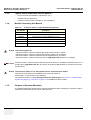
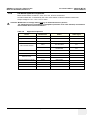
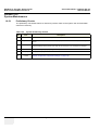
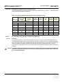
Models Covered by this Manual
Table 1-2
Voluson® 730Pro / 730ProV Model Designations
Part Number
Description
H48651BA
Voluson® 730Pro / 730ProV (BT´04) Console 230V/50Hz
H48651BB
Voluson® 730Pro / 730ProV (BT´04) Console 115V USA
H48651BC
Voluson® 730Pro / 730ProV (BT´04) Console 115V
H48651BD
Voluson® 730Pro / 730ProV (BT´04) Console 100V JAPAN
H48651BE
Voluson® 730Pro / 730ProV (BT´04) Console 230V KOREA
H48651BF
Voluson® 730Pro / 730ProV (BT´04) Console 230V CHINA
NOTICE This manual applies to:
• Voluson® 730Pro / 730ProV systems with Serial number A31501 - 33999,
• Voluson® 730Pro / 730ProV systems with Software version 4.x.x installed,
• Voluson® 730Pro / 730ProV systems that were upgraded to BT´04, and/or
• Voluson® 730Pro / 730ProV systems that were upgraded to BT´05 (SW 5.x.x installed)
BT Version: Voluson® 730Pro / 730ProV systems with serial number less than < A34000 and software version 5.x.x
(simply called: upgraded to BT´05), do have BT´05 software, but hardware is the same than BT´04
systems have!
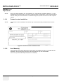
NOTICE The Voluson® 730Pro V is a downgraded version of the Voluson® 730Pro.
That means not all options are available on the Voluson® 730Pro V
(marked with * in the sections of the Manuals).
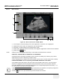
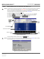
The Voluson® 730Pro V is only distinguished by the System type, see: Figure 7-1: System Setup System Info page (e.g. V730 Pro) on page 7-2; it has NO own serial number!
1-1-5
Purpose of Operator Manual(s)
The Operator Manual(s) should be fully read and understood before operating the Voluson® 730Pro /
730ProV and also kept near the unit for quick reference.
1-2
Section 1-1 - Overview
GE MEDICAL SYSTEMS - KRETZTECHNIK
DIRECTION KTI105947, REVISION 2
DRAFT
VOLUSON® 730PRO / 730PROV (BT´04)
SERVICE MANUAL
Section 1-2
Important Conventions
1-2-1
Conventions Used in Book
Icons
Pictures, or icons, are used wherever they reinforce the printed message. The icons, labels and
conventions used on the product and in the service information are described in this chapter.
Safety Precaution Messages
Various levels of safety precaution messages may be found on the equipment and in the service
information. The different levels of concern are identified by a flag word that precedes the precautionary
message. Known or potential hazards are labeled in one of following ways:
DANGER
DANGER IS USED TO INDICATE THE PRESENCE OF A HAZARD THAT WILL
CAUSE SEVERE PERSONAL INJURY OR DEATH IF THE INSTRUCTIONS ARE
IGNORED.
WARNING
WARNING
WARNING IS USED TO INDICATE THE PRESENCE OF A HAZARD THAT CAN CAUSE
SEVERE PERSONAL INJURY AND PROPERTY DAMAGE IF INSTRUCTIONS ARE
IGNORED.
CAUTION Caution is used to indicate the presence of a hazard that will or can cause minor personal injury
and property damage if instructions are ignored.
NOTICE Equipment Damage Possible
Notice is used when a hazard is present that can cause property damage but has absolutely no
personal injury risk.
Example: Disk drive will crash.
NOTE:
Notes provide important information about an item or a procedure.
Information contained in a NOTE can often save you time or effort.
Chapter 1 - Introduction
1-3
GE MEDICAL SYSTEMS - KRETZTECHNIK
DIRECTION KTI105947, REVISION 2
1-2-2
RAFT
VOLUSON® 730PRO / 730PROV (BT´04)
SERVICE MANUAL
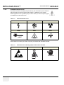
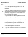
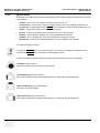
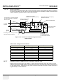
Standard Hazard Icons
Important information will always be preceded by the exclamation point contained
within a triangle, as seen throughout this chapter. In addition to text, several
different graphical icons (symbols) may be used to make you aware of specific types
of hazards that could cause harm.
Table 1-3
Standard Hazard Icons
ELECTRICAL
MECHANICAL
RADIATION
LASER
HEAT
PINCH
LASER
LIGHT
Other hazard icons make you aware of specific procedures that should be followed.
Table 1-4
Standard Icons Indicating a Special Procedure be Used
AVOID STATIC ELECTRICITY
TAG AND LOCK OUT
TAG
&
LOCKOUT
Signed
1-4
Date
Section 1-2 - Important Conventions
WEAR EYE PROTECTION
EYE
PROTECTION
GE MEDICAL SYSTEMS - KRETZTECHNIK
DIRECTION KTI105947, REVISION 2
1-2-3
DRAFT
VOLUSON® 730PRO / 730PROV (BT´04)
SERVICE MANUAL
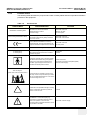
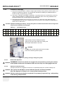
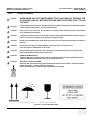
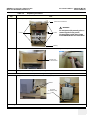
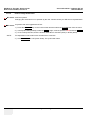
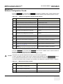
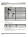
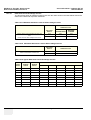
Product Icons
The following table describes the purpose and location of safety labels and other important information
provided on the equipment.
Table 1-5
Product Icons
LABEL/SYMBOL
Identification and Rating Plate
Device Listing/Certification Labels
0123
Type/Class Label
IP Code (IPX 1)
IP Code (IPX 7)
PURPOSE/MEANING
LOCATION
Manufacturer's name and address
Rear side of the unit
Model and serial numbers
Monitor rear side
Electrical ratings
On each probe
Laboratory logo or labels denoting
conformance with industry safety standards
such as UL or IEC.
Council Directive 93/42/EEC concerning
medical devices: The CE mark affixed to the
equipment testifies compliance to the directive.
Rear side of the unit
Rear side of the monitor
Rear side of the unit
on each probe
Used to indicate the degree of safety or protection.
Indicates the degree of protection provided by
the enclosure per IEC 529. IPX 1 and IPX 7
indicates drip proof.
Equipment Type BF (man in the box symbol)
IEC 878-02-03 indicates B Type equipment
having even more electrical isolation than
standard Type B equipment because it is
intended for intimate patient contact.
Footswitch
Probes
Probe connectors
Front side of the ECG-preamplifier (MAN)
Rear of Power Supply
“CAUTION
This unit weighs...
Special care must be used to avoid..."
This precaution is intended to prevent injury
that may result if one person attempt to move
the unit considerable distances or on an incline
due to the weight of the unit.
"CAUTION" The equilateral triangle is usually
used in combination with other symbols to
advise or warn the user.
Various
ATTENTION - Consult accompanying
documents " is intended to alert the user to
refer to the operator manual or other
instructions when complete information cannot
be provided on the label.
Rear side of Power Supply
Chapter 1 - Introduction
1-5
GE MEDICAL SYSTEMS - KRETZTECHNIK
DIRECTION KTI105947, REVISION 2
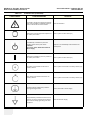
Table 1-5
LABEL/SYMBOL
RAFT
Product Icons (Continued)
PURPOSE/MEANING
LOCATION
"CAUTION - Dangerous voltage" (the lightning
flash with arrowhead in equilateral triangle) is
used to indicate electric shock hazards.
Rear side of Monitor
"Mains OFF" Indicates the power off position of
the mains power switch.
Rear of system at mains switch (F1)
"OFF/Standby" Indicates the power off/
standby position of the power switch.
CAUTION
This Power Switch DOES NOT ISOLATE
Mains Supply
1-6
VOLUSON® 730PRO / 730PROV (BT´04)
SERVICE MANUAL
Adjacent to On-Off/Standby switch left below the
Control panel.
"Mains ON" Indicates the power on position of
the mains power switch.
Rear of system at mains switch (F1)
ON switch of the isolation transformer for
auxiliary devices.
Rear of system at the switch for auxiliary devices (F2)
OFF switch of the isolation transformer for
auxiliary devices.
Rear of system at the switch for auxiliary devices (F2)
"Protective Earth" Indicates the protective
earth (grounding) terminal.
Internal, Rear side of Power Supply
"Equipotentiality" Indicates the terminal to be
used for connecting equipotential conductors
when interconnecting (grounding) with other
equipment.
Rear side of Power Supply
Section 1-2 - Important Conventions
GE MEDICAL SYSTEMS - KRETZTECHNIK
DIRECTION KTI105947, REVISION 2
Table 1-5
DRAFT
VOLUSON® 730PRO / 730PROV (BT´04)
SERVICE MANUAL
Product Icons (Continued)
LABEL/SYMBOL
PURPOSE/MEANING
This symbol indicates that waste electrical and
electronic equipment must not be disposed of
as unsorted municipal waste and must be
collected separately. Please contact an
authorized representative of the manufacturer
for information concerning the
decommissioning of your equipment.
LOCATION
Rear side of the unit
on each probe
Section 1-3
Safety Considerations
1-3-1
Introduction
The following safety precautions must be observed during all phases of operation, service and repair of
this equipment. Failure to comply with these precautions or with specific warnings elsewhere in this
manual, violates safety standards of design, manufacture and intended use of the equipment.
1-3-2
Human Safety
Operating personnel must not remove the system covers.
Servicing should be performed by authorized personnel only.
Only personnel who have participated in a Voluson® 730Pro / 730ProV Training are authorized to
service the equipment.
1-3-3
Mechanical Safety
WARNING
WARNING
USE EXTREME CAUTION WHEN ELEVATING THE UNIT, OR IF IT IS RAISED FOR A
REPAIR OR MOVED ALONG ANY INCLINE. IT MAY BECOME UNSTABLE WHICH
COULD CAUSE THE UNIT TO TIP OVER.
WARNING
WARNING
ULTRASOUND PROBES ARE HIGHLY SENSITIVE MEDICAL INSTRUMENTS THAT
CAN EASILY BE DAMAGED BY IMPROPER HANDLING. USE CARE WHEN
HANDLING AND PROTECT FROM DAMAGE WHEN NOT IN USE. DO NOT USE A
DAMAGED OR DEFECTIVE PROBE. FAILURE TO FOLLOW THESE PRECAUTIONS
CAN RESULT IN SERIOUS INJURY AND EQUIPMENT DAMAGE.
WARNING
WARNING
NEVER USE A PROBE THAT HAS FALLEN TO THE FLOOR. EVEN IF IT LOOKS OK,
IT MAY BE DAMAGED.
CAUTION Always lower and center the Operator I/O Panel before moving the scanner.
CAUTION
The Voluson® 730Pro / 730ProV weighs 136 kg or more, depending on installed peripherals,
(300 lbs., or more) when ready for use. Care must be used when moving it or replacing its
parts. Failure to follow the precautions listed could result in injury, uncontrolled motion and
costly damage.
ALWAYS:
Be sure the pathway is clear and use slow, careful motions.
Use two people when moving on inclines or lifting more than 16 kg (35 lbs).
Chapter 1 - Introduction
1-7
GE MEDICAL SYSTEMS - KRETZTECHNIK
DIRECTION KTI105947, REVISION 2
1-3-3
RAFT
VOLUSON® 730PRO / 730PROV (BT´04)
SERVICE MANUAL
Mechanical Safety (cont’d)
CAUTION Keep the heat venting holes on the monitor unobstructed to avoid overheating of the monitor.
NOTE:
1-3-4
1-3-4-1
Special care should be taken when transporting the unit in a vehicle:
•
Secure the unit in an upright position.
•
Lock the wheels (brake)
•
DO NOT use the Control Panel as an anchor point.
•
Place the probes in their carrying case.
•
Eject any DVD, CD or Magneto Optical disk (MOD) from their drive.
Electrical Safety
Safe Practices
To minimize shock hazard, the equipment chassis must be connected to an electrical ground.
The system is equipped with a three-conductor AC power cable. This must be plugged into an approved
electrical outlet with safety ground. If an extension cord is used with the system, make sure that the total
current rating of the system does not exceed the extension cord rating.
The power outlet used for this equipment should not be shared with other types of equipment.
Both the system power cable and the power connector meet international electrical standards.
WARNING
WARNING
1-3-4-2
CONNECTING A VOLUSON® 730PRO / 730PROV SCANNER TO THE WRONG
VOLTAGE LEVEL WILL MOST LIKELY DESTROY THE SCANNER.
Probes
Follow the guidelines before connecting a probe to the scanner:
•
1-8
Inspect the probe prior to each use for damage or degradation to the:
-
Housing
-
Cable strain relief
-
Lens
-
Seal
•
Do not use a damaged or defective probe.
•
Never immerse the probe connector or adapter into any liquid.
Section 1-3 - Safety Considerations
GE MEDICAL SYSTEMS - KRETZTECHNIK
DIRECTION KTI105947, REVISION 2
1-3-5
DRAFT
VOLUSON® 730PRO / 730PROV (BT´04)
SERVICE MANUAL
Labels Locations
1
2
3
4
5
6
Figure 1-1 Labeling
1.) Caution Label
2.) CE-Label
3.) UL-Label
4.) Identification plate
5.) CW-Doppler (only if the CW-Doppler option is installed)
6.) Homologation label (for Japan only)
1-3-6
Dangerous Procedure Warnings
Warnings, such as the examples below, precede potentially dangerous procedures throughout this
manual. Instructions contained in the warnings must be followed.
DANGER
DANGEROUS VOLTAGES, CAPABLE OF CAUSING DEATH, ARE PRESENT
IN THIS EQUIPMENT.
USE EXTREME CAUTION WHEN HANDLING, TESTING AND ADJUSTING.
WARNING
WARNING EXPLOSION
WARNING
DO NOT OPERATE THE EQUIPMENT IN AN EXPLOSIVE ATMOSPHERE.
OPERATION OF ANY ELECTRICAL EQUIPMENT IN SUCH AN ENVIRONMENT
CONSTITUTES A DEFINITE SAFETY HAZARD.
WARNING
WARNING DO
NOT SUBSTITUTE PARTS OR MODIFY EQUIPMENT
BECAUSE OF THE DANGER OF INTRODUCING ADDITIONAL HAZARDS, DO NOT
INSTALL SUBSTITUTE PARTS OR PERFORM ANY UNAUTHORIZED MODIFICATION
OF THE EQUIPMENT.
Chapter 1 - Introduction
1-9
GE MEDICAL SYSTEMS - KRETZTECHNIK
DIRECTION KTI105947, REVISION 2
1-3-7
RAFT
VOLUSON® 730PRO / 730PROV (BT´04)
SERVICE MANUAL
Lockout/Tagout Requirements (For USA Only)
Follow OSHA Lockout/Tagout requirements by ensuring you are in total control of the electrical Mains
plug.
NOTICE Energy Control and Power Lockout for Voluson® 730Pro / 730ProV.
TAG
&
LOCKOUT
Signed
Date
When servicing parts of the system where there is exposure to voltage greater than 30 Volts:
Unplug the system
Maintain control of the system power plug
There are no test points to verify isolation, you must wait for at least 20 seconds for capacitors to
discharge.
Beware that the Power Supply (CPN), Front End Processor and Back End Processor may be energized
even if the power is turned off when the cord is still plugged into the AC Outlet.
UT
1-3-8
Returning/Shipping Probes and Repair Parts
Equipment being returned must be clean and free of blood and other infectious substances.
GEMS policy states that body fluids must be properly removed from any part or equipment prior to
shipment. GEMS employees, as well as customers, are responsible for ensuring that parts/equipment
have been properly decontaminated prior to shipment. Under no circumstance should a part or
equipment with visible body fluids be taken or shipped from a clinic or site (for example, body coils or
and ultrasound probe).
The purpose of the regulation is to protect employees in the transportation industry, as well as the
people who will receive or open this package.
NOTE:
The US Department of Transportation (DOT) has ruled that “items what were saturated and/or
dripping with human blood that are now caked with dried blood; or which were used or intended
for use in patient care” are “regulated medical waste” for transportation purpose and must be
transported as a hazardous material.
Section 1-4
Electromagnetic Compatibility (EMC)
1-4-1
What is EMC?
Electromagnetic compatibility describes a level of performance of a device within its electromagnetic
environment. This environment consists of the device itself and its surroundings including other
equipment, power sources and persons with which the device must interface. Inadequate compatibility
results when a susceptible device fails to perform as intended due interference from its environment or
when the device produces unacceptable levels of emission to its environment. This interference is often
referred to as radio–frequency or electromagnetic interference (RFI/EMI) and can be radiated through
space or conducted over interconnecting power of signal cables. In addition to electromagnetic energy,
EMC also includes possible effects from electrical fields, magnetic fields, electrostatic discharge and
disturbances in the electrical power supply.
For applicable standards refer to Chapter 2 in the Basic User Manual.
1-10
Section 1-4 - Electromagnetic Compatibility (EMC)
GE MEDICAL SYSTEMS - KRETZTECHNIK
DIRECTION KTI105947, REVISION 2
1-4-2
DRAFT
VOLUSON® 730PRO / 730PROV (BT´04)
SERVICE MANUAL
Compliance
The Voluson® 730Pro / 730ProV unit conforms to all applicable conducted and radiated emission limits
and to immunity from electrostatic discharge, radiated and conducted RF fields, magnetic fields and
power line transient requirements.
NOTE:
1-4-3
For CE Compliance, it is critical that all covers, screws, shielding, gaskets, mesh, clamps, are in
good condition, installed tightly without skew or stress. Proper installation following all
comments noted in this service manual is required in order to achieve full EMC performance.
Electrostatic Discharge (ESD) Prevention
WARNING
WARNING
DO NOT TOUCH ANY BOARDS WITH INTEGRATED CIRCUITS PRIOR TO TAKING THE
NECESSARY ESD PRECAUTIONS:
1. ALWAYS CONNECT YOURSELF, VIA AN ARM-WRIST STRAP, TO THE ADVISED ESD
CONNECTION POINT LOCATED ON THE REAR OF THE SCANNER (TO THE RIGHT OF
THE POWER CONNECTOR).
2. FOLLOW GENERAL GUIDELINES FOR HANDLING OF ELECTROSTATIC SENSITIVE
EQUIPMENT.
WARNING
WARNING
Risk of electrical shock, system must be turned off. Avoid all contact with electrical
contacts, conductors and components. Always use non-conductive handles designed
for the removal and replacement of ESD sensitive parts. All parts that have the potential
for storing energy must be discharged or isolated before making contact.
Section 1-5
Customer Assistance
1-5-1
Contact Information
If this equipment does not work as indicated in this service manual or in the Basic User Manual, or if
you require additional assistance, please contact the local distributor or appropriate support resource,
as listed below.
NOTE:
Prepare vital system information (see: Section 7-2 on page 7-2) before you call:
•
System Type
•
System Serial number (also visible on label on back of the system)
•
Application Software version
•
Backup version
•
additional information about installed software
Chapter 1 - Introduction
1-11
GE MEDICAL SYSTEMS - KRETZTECHNIK
DIRECTION KTI105947, REVISION 2
1-5-1
RAFT
VOLUSON® 730PRO / 730PROV (BT´04)
SERVICE MANUAL
Contact Information (cont’d)
Table 1-6
Phone Numbers for Customer Assistance
Location
Phone Number
1-800–437–1171
USA/ Canada
GE Medical Systems
Ultrasound Service Engineering
4855 W. Electric Avenue
Milwaukee, WI 53219
1-800-682-5327
Customer Answer Center
1-262-524-5698
Fax: +1-414-647-4125
1-262-524-5300
Latin America
GE Medical Systems
Ultrasound Service Engineering
4855 W. Electric Avenue
Milwaukee, WI 53219
1-262-524-5698
Customer Answer Center
Fax: +1-414-647-4125
Europe
GE Medical Systems Kretztechnik GmbH & Co OHG
Service Department - Ultrasound
Tel: +43 (0)7682 3800-26
Fax: +43 (0)7682 3800-47
Tiefenbach 15
A-4871 Zipf
Austria
Tel: +33-13083-1300
Customer Answer Center
Asia
Tel: +65 6291-8528
GE Ultrasound Asia
+81 426-482950
Service Department - Ultrasound
298 Tiong Bahru Road #15-01/06
Central Plaza
Singapore 169730
1-5-2
Fax: +65 6272-7006
System Manufacturer
Table 1-7
System Manufacturer
Manufacturer
Telephone
FAX
+43-7682-3800-0
+43-7682-3800-47
GE Medical Systems
Kretztechnik GmbH & Co OHG
Tiefenbach 15
A-4871 Zipf
Austria
1-12
Section 1-5 - Customer Assistance
GE MEDICAL SYSTEMS - KRETZTECHNIK
DIRECTION KTI105947, REVISION 2
DRAFT
VOLUSON® 730PRO / 730PROV (BT´04)
SERVICE MANUAL
Chapter 2
Pre-Installation
Section 2-1
Overview
2-1-1
Purpose of Chapter 2
This chapter provides the information required to plan and prepare for the installation of a Voluson®
730Pro / 730ProV. Included are descriptions of the facility and electrical needs to be met by the
purchaser of the unit.
Table 2-1
Contents in Chapter 2
Section
Description
Page Number
2-1
Overview
2-1
2-2
General Console Requirements
2-2
2-3
Facility Needs
2-6
Chapter 2 - Pre-Installation
2-1
GE MEDICAL SYSTEMS - KRETZTECHNIK
DIRECTION KTI105947, REVISION 2
RAFT
VOLUSON® 730PRO / 730PROV (BT´04)
SERVICE MANUAL
Section 2-2
General Console Requirements
2-2-1
Console Environmental Requirements
Table 2-2
Environmental Requirements
Operating
Temperature
10 to
40oC
(50 to 104oF)
2-2-1-1
Operating
Humidity
30 to 80% rH
non-condensing
Heat Dissipation
3446 BTU pr hour
Storage
Temperature
-10 to 40
oC
(14 to 104oF)
Storage Humidity
< 90% rH noncondensing
Cooling
The cooling requirement for the Voluson® 730Pro / 730ProV is 3446 BTU/hr. This figure does not
include cooling needed for lights, people, or other equipment in the room. Each person in the room
places an additional 300 BTU/hr. demand on the cooling system.
2-2-1-2
Lighting
Bright light is needed for system installation, updates and repairs. However, operator and patient
comfort may be optimized if the room light is subdued and indirect. Therefore a combination lighting
system (dim/bright) is recommended. Keep in mind that lighting controls and dimmers can be a source
of EMI which could degrade image quality. These controls should be selected to minimize possible
interference.
2-2-2
NOTE:
2-2-2-1
Electrical Requirements
GE Medical Systems requires a dedicated power and ground for the proper operation of its
Ultrasound equipment. This dedicated power shall originate at the last distribution panel before
the system. The dedicated line shall consist of one phase, a neutral (not shared with any other
circuit), and a full size ground wire from the distribution panel to the Ultrasound outlet. Please
note that image artifacts can occur, if at any time within the facility, the ground from the main
facility's incoming power source to the Ultrasound unit is only a conduit.
Voluson® 730Pro / 730ProV Power Requirements
Table 2-3
2-2-2-2
Electrical Specifications for Voluson® 730Pro / 730ProV
Voltage
Tolerances
Current
Frequency
100 VAC
±10%
10.10 A
50, 60 Hz (±2%)
110 VAC
±10%
9.20 A
50, 60 Hz (±2%)
115 VAC
±10%
8.80 A
50, 60 Hz (±2%)
130 VAC
±10%
7.80 A
50, 60 Hz (±2%)
230 VAC
±10%
4.40 A
50, 60 Hz (±2%)
240 VAC
±10%
4.20 A
50, 60 Hz (±2%)
Inrush Current
Inrush current is not a factor to consider due to the inrush current limiting properties of the power
supplies.
2-2
Section 2-2 - General Console Requirements
GE MEDICAL SYSTEMS - KRETZTECHNIK
DIRECTION KTI105947, REVISION 2
2-2-2-3
DRAFT
VOLUSON® 730PRO / 730PROV (BT´04)
SERVICE MANUAL
Site Circuit Breaker
It is recommended that the branch circuit breaker for the machine be readily accessible.
CAUTION POWER OUTAGE MAY OCCUR.
The Voluson® 730Pro / 730ProV requires a dedicated single branch circuit. To avoid circuit
overload and possible loss of critical care equipment, make sure you DO NOT have any other
equipment operating on the same circuit.
2-2-2-4
Site Power Outlets
A dedicated AC power outlet must be within reach of the unit without extension cords. Other adequate
outlets for the external peripherals, medical and test equipment needed to support this unit must also
be present within 1 m (3.2 ft.) of the unit. Electrical installation must meet all current local, state, and
national electrical codes.
2-2-2-5
Unit Power Plug
If the unit arrives without a power plug, or with the wrong plug, you must contact your GE dealer or the
installation engineer must supply what is locally required.
Chapter 2 - Pre-Installation
2-3
GE MEDICAL SYSTEMS - KRETZTECHNIK
DIRECTION KTI105947, REVISION 2
2-2-3
RAFT
VOLUSON® 730PRO / 730PROV (BT´04)
SERVICE MANUAL
EMI Limitations
Ultrasound machines are susceptible to Electromagnetic Interference (EMI) from radio frequencies,
magnetic fields, and transients in the air or wiring. Ultrasound machines also generate EMI. The
Voluson® 730Pro / 730ProV complies with limits as stated on the EMC label. However, there is no
guarantee that interference will not occur in a particular installation.
Possible EMI sources should be identified before the unit is installed.
Electrical and electronic equipment may produce EMI unintentionally as the result of a defect.
These sources include:
•
medical lasers,
•
scanners,
•
cauterizing guns,
•
computers,
•
monitors,
•
fans,
•
gel warmers,
•
microwave ovens,
•
light dimmers
•
portable phones.
The presence of a broadcast station or broadcast van may also cause interference.
see Table 2-4 for EMI Prevention tips
Table 2-4
EMI Prevention/Abatement
EMI Rule
Details
Be aware of RF sources
Keep the unit at least 5 meters or 15 feet away from other EMI sources. Special shielding may be
required to eliminate interference problems caused by high frequency, high powered radio or video
broadcast signals.
Ground the unit
Poor grounding is the most likely reason a unit will have noisy images. Check grounding of the
power cord and power outlet.
Replace all screws, RF
gaskets, covers, cores
After you finish repairing or updating the system, replace all covers and tighten all screws. Any
cable with an external connection requires a magnet wrap at each end. Install the shield over the
front of card cage. Loose or missing covers or RF gaskets allow radio frequencies to interfere with
the ultrasound signals.
Replace broken RF gaskets
If more than 20% or a pair of the fingers on an RF gasket are broken, replace the gasket. Do not
turn on the unit until any loose metallic part is removed.
Do not place labels where
RF gaskets touch metal
Never place a label where RF gaskets meet the unit. Otherwise, the gap created will permit RF
leakage. Or, if a label has been found in such a position, move the label.
Use GE specified harnesses The interconnect cables are grounded and require ferrite beads and other shielding. Also, cable
and peripherals
length, material, and routing are all important; do not change from what is specified.
2-4
Take care with cellular
phones
Cellular phones may transmit a 5 V/m signal; that could cause image artifacts.
Properly dress peripheral
cables
Do not allow cables to lie across the top of the card cage or hang out of the peripheral bays. Loop
the excess length for peripheral cables inside the peripheral bays. Attach the monitor cables to the
frame.
Section 2-2 - General Console Requirements
GE MEDICAL SYSTEMS - KRETZTECHNIK
DIRECTION KTI105947, REVISION 2
2-2-4
DRAFT
VOLUSON® 730PRO / 730PROV (BT´04)
SERVICE MANUAL
Scan Probe Environmental Requirements
Operation: Ambient temperature 18° to 30° C
Storage: -10° to 50° C
NOTE:
Temperature in degrees C. Conversion to degrees F = °C (9/5) + 32).
NOTICE SYSTEMS AND ELECTRONIC PROBES ARE DESIGNED FOR STORAGE TEMPERATURES OF
-10 TO + 50 degrees C. WHEN EXPOSED TO LARGE TEMPERATURE VARIATIONS, THE
PRODUCT SHOULD BE KEPT IN ROOM TEMPERATURE FOR 10 HOURS BEFORE USE.
2-2-5
Time and Manpower Requirements
Site preparation takes time. Begin Pre-installation checks as soon as possible. If possible, allow six
weeks before delivery, for enough time to make necessary changes.
CAUTION Have two people available to deliver and unpack the Voluson® 730Pro / 730ProV.
Attempts to move the unit considerable distances or on an incline by one person could result
in injury or damage or both.
Chapter 2 - Pre-Installation
2-5
GE MEDICAL SYSTEMS - KRETZTECHNIK
DIRECTION KTI105947, REVISION 2
RAFT
VOLUSON® 730PRO / 730PROV (BT´04)
SERVICE MANUAL
Section 2-3
Facility Needs
2-3-1
Purchaser Responsibilities
The work and materials needed to prepare the site is the responsibility of the purchaser. Delay,
confusion, and waste of manpower can be avoided by completing pre installation work before delivery.
Use the Pre installation checklist to verify that all needed steps have been taken. Purchaser
responsibility includes:
NOTE:
•
Procuring the materials required.
•
Completing the preparations before delivery of the ultrasound system.
•
Paying the costs for any alterations and modifications not specifically provided in the sales contract.
All electrical installations that are preliminary to the positioning of the equipment at the site prepared for
the equipment must be performed by licensed electrical contractors. Other connections between pieces
of electrical equipment, calibrations, and testing must also be performed by qualified personnel. The
products involved (and the accompanying electrical installations) are highly sophisticated and special
engineering competence is required. All electrical work on these products must comply with the
requirements of applicable electrical codes. The purchaser of GE equipment must only utilize qualified
personnel to perform electrical servicing on the equipment.
The desire to use a non–listed or customer provided product or to place an approved product further
from the system than the interface kit allows presents challenges to the installation team. To avoid
delays during installation, such variances should be made known to the individuals or group performing
the installation at the earliest possible date (preferably prior to the purchase).
The ultrasound suite must be clean prior to delivery of the machine. Carpet is not recommended
because it collects dust and creates static. Potential sources of EMI (electromagnetic interference)
should also be investigated before delivery. Dirt, static, and EMI can negatively impact system reliability.
2-3-2
NOTE:
NOTE:
2-6
Required Features
GE Medical Systems requires a dedicated power and ground for the proper operation of its
Ultrasound equipment. This dedicated power shall originate at the last distribution panel before
the system. The dedicated line shall consist of one phase, a neutral (not shared with any other
circuit), and a full size ground wire from the distribution panel to the Ultrasound outlet. Please
note that image artifacts can occur, if at any time within the facility, the ground from the main
facility's incoming power source to the Ultrasound unit is only a conduit.
•
Door opening is at least 76 cm (30 in) wide.
•
Proposed location for unit is at least 0.3 m (1 ft.) from the wall for cooling
•
Power outlet and place for any external peripheral are within 2 m (6.5 ft) of each other with
peripheral within 1 m of the unit to connect cables.
The Voluson® 730Pro / 730ProV has four outlets inside the unit. One is for the monitor and three for on
board peripherals.
Section 2-3 - Facility Needs
GE MEDICAL SYSTEMS - KRETZTECHNIK
DIRECTION KTI105947, REVISION 2
2-3-3
DRAFT
VOLUSON® 730PRO / 730PROV (BT´04)
SERVICE MANUAL
Desirable Features
•
Door is at least 90 cm (3 ft.) wide
•
Circuit breaker for dedicated power outlet is easily accessible
•
Sink with hot and cold water
•
Receptacle for bio–hazardous waste, like used probe sheaths
•
Emergency oxygen supply
•
Storage for linens and equipment
•
Nearby waiting room, lavatory, and dressing room
•
Dual level lighting (bright and dim)
•
Lockable cabinet ordered by GE for its software and proprietary manuals
Chapter 2 - Pre-Installation
2-7
GE MEDICAL SYSTEMS - KRETZTECHNIK
DIRECTION KTI105947, REVISION 2
2-3-4
RAFT
Minimal Floor Plan Suggestion
Figure 2-1 Minimal Floor Plan
2-8
Section 2-3 - Facility Needs
VOLUSON® 730PRO / 730PROV (BT´04)
SERVICE MANUAL
GE MEDICAL SYSTEMS - KRETZTECHNIK
DIRECTION KTI105947, REVISION 2
2-3-5
2-3-5-1
DRAFT
VOLUSON® 730PRO / 730PROV (BT´04)
SERVICE MANUAL
Networking Pre-installation Requirements
Purpose of the DICOM Network Function
DICOM (Digital Imaging and Communications in Medicine) services provide the operator with clinically
useful features for moving images and patient information over a hospital network.
Examples of DICOM services include the transfer of images to workstations for viewing or transferring
images to remote printers. As an added benefit, transferring images in this manner frees up the onboard monitor and peripherals, enabling viewing to be done while scanning continues.
With DICOM, images can be archived, stored, and retrieved faster, easier, and at a lower cost.
2-3-5-2
DICOM Option Pre-installation Requirements
To configure the Voluson® 730Pro / 730ProV to work with other network connections, the site’s network
administrator must provide some necessary information.
Information must include:
•
A Station name, AE Title, IP address and Net Mask for the Voluson® 730Pro / 730ProV.
•
The IP addresses for the default gateway and other routers at the site for ROUTING
INFORMATION. Only if necessary (e.g. for Internet access).
Installation see: Section 3-12 "Network IP Address Configuration" on page 3-50.
Chapter 2 - Pre-Installation
2-9
GE MEDICAL SYSTEMS - KRETZTECHNIK
DIRECTION KTI105947, REVISION 2
RAFT
This page was intentionally left blank.
2-10
Section 2-3 - Facility Needs
VOLUSON® 730PRO / 730PROV (BT´04)
SERVICE MANUAL
GE MEDICAL SYSTEMS - KRETZTECHNIK
DIRECTION KTI105947, REVISION 2
DRAFT
VOLUSON® 730PRO / 730PROV (BT´04)
SERVICE MANUAL
Chapter 3
Installation
Section 3-1
Overview
3-1-1
The Purpose of Chapter 3
This chapter contains information needed to install the unit. Included are procedures to receive, unpack
and configure the equipment.
Table 3-1
Contents in Chapter 3
Section
Description
Page Number
3-1
Overview
3-1
3-2
Installation Reminders
3-1
3-3
Receiving and Unpacking the Equipment
3-4
3-4
Preparing for Installation
3-6
3-5
Connection of Auxiliary Devices
3-7
3-6
Completing the Installation
3-20
3-7
Printer Installation
3-23
3-8
System Configuration
3-39
3-9
Available Probes
3-47
3-10
Software/Option Configuration
3-48
3-11
Connectivity Installation Worksheet
3-49
3-12
Network IP Address Configuration
3-50
3-13
Paperwork
3-52
Section 3-2
Installation Reminders
3-2-1
Average Installation Time
Table 3-2
Average Installation Time
Description
Average Installation Time
Unpacking the scanner
0.5 hours
Scanner /options / printers
0.5 to 1.5 hours
Dependant on the required configuration
DICOM Option
0.5 - 1.5 hours
Dependant on the configuration amount
Chapter 3 - Installation
Comments
3-1
GE MEDICAL SYSTEMS - KRETZTECHNIK
DIRECTION KTI105947, REVISION 2
3-2-2
RAFT
VOLUSON® 730PRO / 730PROV (BT´04)
SERVICE MANUAL
Installation Warnings
1.) Since the Voluson® 730Pro / 730ProV weighs approximately 136 kg (300 lb.) without options, two
people are required to unpack it. Two people are required for installing any additional items in
excess of 16kg / 35 pounds (e.g., Monitor).
2.) There are no operator serviceable components. To prevent shock, do not remove any covers or
panels. Should problems or malfunctions occur, unplug the power cord. Only qualified service
personnel should carry out servicing and troubleshooting.
3.) After being transported, the unit may be very cold or hot. If this is the case, allow the unit to
acclimate before you turn it on. It requires one hour for each 2.5°C increment it's temperature is
below 10°C or above 40°C.
CAUTION Equipment damage possibility. Turning the system on without acclimation after arriving at site
may cause the system to be damaged.
Table 3-3
Acclimation Time
°C
60
55
50
45
40
35
30
25
20
15
10
5
0
-5
-10
-15
-20
-25
-30
-35
-40
°F
140
131
122
113
104
96
86
77
68
59
50
41
32
23
14
5
-4
-13
-22
-31
-40
hrs
8
6
4
2
0
0
0
0
0
0
0
2
4
6
8
10
12
14
16
18
20
When pulling, moving or lifting the system,
grasp it only at the rear handle of the trolley and
the handle underneath the foot rest.
WARNING
Do NOT pull or lift the system with the front handle
of the user interface (operator panel).
Figure 3-1 pulling, moving or lifting the system
3-2-2-1
WARNING
WARNING
3-2-2-2
Brake Pedal Operation
REMEMBER: If the front wheels are engaged for transportation, pressing the release
brake pedals (brakes on front wheels under the foot rest) once disengages the lock.
Operator I/O Panel Position
If weight is placed on the Operator I/O Panel in it’s extended position the console could tip over.
3-2
WARNING
WARNING
The system should NOT be moved with the Operator I/O Panel extended.
Move the Operator I/O Panel to it’s centered and locked position.
WARNING
WARNING
Monitor mounting mechanism may break if not properly supported (e.g., with packing
foam) during transportation.
Section 3-2 - Installation Reminders
GE MEDICAL SYSTEMS - KRETZTECHNIK
DIRECTION KTI105947, REVISION 2
3-2-3
DRAFT
VOLUSON® 730PRO / 730PROV (BT´04)
SERVICE MANUAL
Safety Reminders
DANGER
WHEN USING ANY TEST INSTRUMENT THAT IS CAPABLE OF OPENING THE
AC GROUND LINE (I.E., METER’S GROUND SWITCH IS OPEN), DON’T TOUCH
THE UNIT!
CAUTION
Two people should unpack the unit because of its weight. Two people are required whenever
a part weighing 16kg (35 lb.) or more must be lifted.
CAUTION
If the unit is very cold or hot, do not turn on its power until it has had a chance to acclimate
to its operating environment.
CAUTION
To prevent electrical shock, connect the unit to a properly grounded power outlet. Do not use
a three to two prong adapter. This defeats safety grounding.
CAUTION
Do NOT wear the ESD wrist strap when you work on live circuits and more than 30 V peak is
present.
CAUTION
Do not use a 20 Amp to 15 Amp adapter on the 120 Vac unit’s power cord.
This unit requires a dedicated 16 A circuit.
CAUTION
Do not operate this unit unless all board covers and frame panels are securely in place.
System performance and cooling require this.
CAUTION
OPERATOR MANUAL(S)
The User Manual(s) should be fully read and understood before operating the Voluson®
730Pro / 730ProV and kept near the unit for quick reference.
CAUTION
ACOUSTIC OUTPUT HAZARD
Although the ultrasound energy transmitted from the Voluson® 730Pro / 730ProV probe is
within FDA limits, avoid unnecessary exposure.
Ultrasound energy can produce heat and mechanical damage.
Figure 3-2 Environmental Labels
Chapter 3 - Installation
3-3
GE MEDICAL SYSTEMS - KRETZTECHNIK
DIRECTION KTI105947, REVISION 2
RAFT
VOLUSON® 730PRO / 730PROV (BT´04)
SERVICE MANUAL
Section 3-3
Receiving and Unpacking the Equipment
CAUTION
Transport only with forklift or stracker truck.
During transport pay attention to the point of gravity (“tilt and drop” indicator)!
Have two people available to unpack the Voluson® 730Pro / 730ProV.
Attempts to move the unit considerable distances or on an incline by one person could result
in injury or damage or both.
The envelope with delivery address, packing list and
invoice is located on the front panel of the crate.
Check whether delivery is complete (according to
packing list) and check visual damage!
Figure 3-3 envelope at front panel of the crate
NOTICE The device must only be transported in the original packaging!
Unpack the devices such a way that packaging can be reused.
A drill with size 20 torx bit and/or a Phillips 2 screwdriver is needed to open the crate.
Table 3-4
Step
1.
Unpacking Procedure
Task
Loosen the screws and remove top panel from crate; top panel is used for the ramp.
tilt and drop
indicator
center
of
gravity
3-4
Section 3-3 - Receiving and Unpacking the Equipment
GE MEDICAL SYSTEMS - KRETZTECHNIK
DIRECTION KTI105947, REVISION 2
Table 3-4
DRAFT
Unpacking Procedure
Step
2.
VOLUSON® 730PRO / 730PROV (BT´04)
SERVICE MANUAL
Task
Open front panel by removing the screws from the side panels. Remove probes and accessories from the wooden box.
probes and accessories
WARNING
WARNING
screws
screws
Do not open side panels prior to
removing the front panel!
Accessories could drop down
and DAMAGE the user interface!
packing
3.
Loosen all screws to remove the wooden rack for accessories as well as the left, right and back panel.
wooden rack
for accessories
4.
Carefully remove foam packing material and plastic bag from the ultrasound unit and monitor.
Caution: Two people are needed in the next step due to the weight of the equipment.
5.
Disengage the brakes and slowly move unit down the ramp (top panel).
brakes
Brakes
top panel
is used for ramp
Note: Packing crate and material should be stored for future use.
Chapter 3 - Installation
3-5
GE MEDICAL SYSTEMS - KRETZTECHNIK
DIRECTION KTI105947, REVISION 2
RAFT
VOLUSON® 730PRO / 730PROV (BT´04)
SERVICE MANUAL
Section 3-4
Preparing for Installation
3-4-1
Verify Customer Order
Compare items received by the customer to that which is listed on the delivery order.
Report any items that are missing, back ordered or damaged.
3-4-2
3-4-2-1
Physical Inspection
System Voltage Settings
Verify that the scanner is set to the correct voltage. The Voltage settings for the Voluson® 730Pro /
730ProV Scanner is found on the identification plate, on the rear of the system.
Figure 3-4 Identification Plate
WARNING
WARNING
3-4-3
CONNECTING A Voluson® 730Pro / 730ProV SCANNER TO THE WRONG VOLTAGE
LEVEL WILL MOST LIKELY DESTROY THE SCANNER.
EMI Protection
This unit has been designed to minimize the effects of Electo-Magnetic Interference (EMI). Many of the
covers, shields, and screws are provided primarily to protect the system from image artifacts caused by
this interference. For this reason, it is imperative that all covers and hardware are installed and secured
before the unit is put into operation.
3-6
Section 3-4 - Preparing for Installation
GE MEDICAL SYSTEMS - KRETZTECHNIK
DIRECTION KTI105947, REVISION 2
DRAFT
VOLUSON® 730PRO / 730PROV (BT´04)
SERVICE MANUAL
Section 3-5
Connection of Auxiliary Devices
NOTE:
Normally the auxiliary devices and peripherals come already installed with the system.
GES - External IO Board
wall power socket
VGA
MODEM
NET
COMP VIDEO
OUT
USB
cable
GEM - Disk Drive Module
LINE PRINTER
SUPPLY
USB
ECG
MODEM
POWER
RS232
Power
supply
USB
TEL
IN
OUT
OUT
POWER
SW PRINTER
S-VHS-VIDEORECORDER
VIDEO IN
REMOTE
COLOR PRINTER
IN
AUDIO VIDEO
USB
POWER
Out
AUDIO VIDEO
RS232
PC
USB-GEM
Parallel Port
POWER
USB
RS-232
POWER
Line Out MIC Line In
USB
USB
CKV
VGA2
VGA1
RGB
VHS1
S-VHS1
VHS2
S-VHS2
VHS
S-VHS
LAN1
CPE
PS2 VGA
AUX SUPPLY
AUDIO IN REMOTE
SOUND BW PRINTER
CONSOLE
CPN
LAMP
RS232
ECG
AUDIO
OUT IN
UI Disp.
Foot Switch
CPN
Primary-Power-Supply
FootSwitch
Figure 3-5 Connection of Peripherals
Chapter 3 - Installation
3-7
GE MEDICAL SYSTEMS - KRETZTECHNIK
DIRECTION KTI105947, REVISION 2
Section 3-5
RAFT
VOLUSON® 730PRO / 730PROV (BT´04)
SERVICE MANUAL
Connection of Auxiliary Devices (cont’d)
1.) Carefully remove plastic caps using a knife and loosen screws and washers (see: Figure 3-6).
2.) When the cover is loose on top, pull the rear cover out and move upwards.
plastic caps; screw and washers
Figure 3-6 Remove rear cover plate
3.) Disconnect the GND ground-cable from the back of the rear cover plate.
GND ground cable
Figure 3-7 GND ground-cable
4.) Connect all Peripherals according to connection scheme; see: Figure 3-5.
5.) Connect the GND ground-cable at the rear cover plate.
6.) Mount rear cover plate, reattach screw and washers and plug-in the caps.
3-8
Section 3-5 - Connection of Auxiliary Devices
GE MEDICAL SYSTEMS - KRETZTECHNIK
DIRECTION KTI105947, REVISION 2
3-5-1
NOTE:
3-5-2
NOTE:
DRAFT
VOLUSON® 730PRO / 730PROV (BT´04)
SERVICE MANUAL
Monitor Connection
The monitor comes already installed with the system.
Foot Switch Connection
To adjust the Foot Switch, refer to the Voluson® 730Pro / 730ProV Basic User Manual,
Chapter 17.3.3, System Setup - Peripherals.
Figure 3-8 Foot Switch Connection Scheme
Chapter 3 - Installation
3-9
GE MEDICAL SYSTEMS - KRETZTECHNIK
DIRECTION KTI105947, REVISION 2
3-5-3
RAFT
VOLUSON® 730PRO / 730PROV (BT´04)
SERVICE MANUAL
ECG-preamplifier Connection
Figure 3-9 ECG Connection Scheme
3-10
Section 3-5 - Connection of Auxiliary Devices
GE MEDICAL SYSTEMS - KRETZTECHNIK
DIRECTION KTI105947, REVISION 2
3-5-4
DRAFT
VOLUSON® 730PRO / 730PROV (BT´04)
SERVICE MANUAL
Global Modem Connection
Figure 3-10 Global Modem Connection Scheme
WARNING
WARNING
Never install the telephone wiring, or use the modem during an electric storm;
there may be a remote risk of electrical shock from lightning.
CAUTION Use only the power adapter supplied with the modem and connect it as shown.
Use of any other power adapter will void the warranty and could damage the modem.
Chapter 3 - Installation
3-11
GE MEDICAL SYSTEMS - KRETZTECHNIK
DIRECTION KTI105947, REVISION 2
3-5-5
3-5-5-1
RAFT
VOLUSON® 730PRO / 730PROV (BT´04)
SERVICE MANUAL
S-VHS Video Recorder Connection
Mitsubishi HS-MD3000
CAUTION ONLY the specific GE - Kretztechnik Version of this video recorder type may be used in
connection with the system!
Figure 3-11 Mitsubishi - Video Recorder Connection Scheme
NOTICE Please use the proper connection set and remote cable.
see: Section 9-12 "Optional Peripherals and Accessories" on page 9-25.
3-12
Section 3-5 - Connection of Auxiliary Devices
GE MEDICAL SYSTEMS - KRETZTECHNIK
DIRECTION KTI105947, REVISION 2
3-5-5-2
DRAFT
VOLUSON® 730PRO / 730PROV (BT´04)
SERVICE MANUAL
Sony SVO-9500MD
Figure 3-12 Video Recorder Connection Scheme
Set DIP Switches on back of the VCR as shown:
Switch 1:
OFF-Audio is muted during fast playback
Switch 2:
OFF-FF/REW mode is used during searches.
Switch 3:
ON-VCR counter is reset upon cassette ejection.
Switch 4:
OFF-The VCR can be controlled by the system.
Switch 5 + 6:
ON-The Baud rate is set to 19200 bit/sec
(must be the same as Voluson® 730Pro / 730ProV)
Figure 3-13 DIP Switches
NOTICE Please use the proper connection set and remote cable.
see: Section 9-12 "Optional Peripherals and Accessories" on page 9-25.
Chapter 3 - Installation
3-13
GE MEDICAL SYSTEMS - KRETZTECHNIK
DIRECTION KTI105947, REVISION 2
3-5-6
RAFT
VOLUSON® 730PRO / 730PROV (BT´04)
SERVICE MANUAL
B/W Video Printer Connection
Figure 3-14 B/W Video Printer Connection Scheme
Set DIP Switches on back of the Black/White printer as shown in the image (all DOWN).
NOTICE Please use the proper connection set.
see: Section 9-12 "Optional Peripherals and Accessories" on page 9-25.
3-14
Section 3-5 - Connection of Auxiliary Devices
GE MEDICAL SYSTEMS - KRETZTECHNIK
DIRECTION KTI105947, REVISION 2
3-5-7
DRAFT
VOLUSON® 730PRO / 730PROV (BT´04)
SERVICE MANUAL
Line Printer Connection
Figure 3-15 Line Printer Connection Scheme
CAUTION Please observe that the Line Printer (HP 990cxi or HP 995c) has to be located outside of the
patient environment (acc. IEC 60601-1 / UL 2601-1).
NOTICE The switch of the printer has to be in ON position before starting the system.
Leave printer switch always in the ON position.
NOTICE Please use the proper connection set.
NOTE:
For further installation instructions see:
Section 3-7-1 "Installing Line Printer HP 990cxi or HP 995c" on page 3-24.
Chapter 3 - Installation
3-15
GE MEDICAL SYSTEMS - KRETZTECHNIK
DIRECTION KTI105947, REVISION 2
3-5-8
RAFT
VOLUSON® 730PRO / 730PROV (BT´04)
SERVICE MANUAL
Digital Color Printer Connection
Figure 3-16 Digital Color Printer Connection Scheme
CAUTION Pay attention to lateral distances. See Instruction Manual of the printer!
CAUTION The Printer Supply Voltage must be the same as the Output Voltage of the Voluson® 730Pro /
730ProV Power Out Connectors (Power Supply)!
NOTICE The switch of the printer has to be in ON position before starting the system.
Leave printer switch always in the ON position.
NOTICE Please use the proper connection set.
see: Section 9-12 "Optional Peripherals and Accessories" on page 9-25.
CAUTION The Sony UP-D23MD printer must never be connected to USB-ports on the SBC backplane.
Please use one of the two outlets on the back of the GEM (Disk Drive Module) only.
NOTE:
3-16
For further installation instructions see:
Section 3-7-2 "Installing Digital Color Printer Sony UP-D21MD or UP-D23MD" on page 3-26.
Section 3-5 - Connection of Auxiliary Devices
GE MEDICAL SYSTEMS - KRETZTECHNIK
DIRECTION KTI105947, REVISION 2
3-5-9
DRAFT
VOLUSON® 730PRO / 730PROV (BT´04)
SERVICE MANUAL
Bluetooth Printer Connection
Figure 3-17 Bluetooth Printer Connection Scheme
CAUTION Please observe that the complete Bluetooth Printer Assembly has to be located outside of the
patient environment (acc. IEC 60601-1 / UL 2601-1).
CAUTION The used printer may not be a medical device. The Bluetooth Printer Set and the Power Supply
of the Bluetooth Printer Adapter is also not a medical device.
The equipment meets the requirements of the EN60950 Standard.
NOTICE The switch of the printer has to be in ON position before starting the system.
Leave printer switch always in the ON position.
NOTICE Please use the proper Bluetooth Printer Connection set.
see: Section 9-12 "Optional Peripherals and Accessories" on page 9-25.
Chapter 3 - Installation
3-17
GE MEDICAL SYSTEMS - KRETZTECHNIK
DIRECTION KTI105947, REVISION 2
3-5-10
3-5-10-1
RAFT
VOLUSON® 730PRO / 730PROV (BT´04)
SERVICE MANUAL
External USB-Devices
Connection
When an external USB-storage device (such as a USB-memory stick or an external hard disk) is
connected to the Voluson® 730Pro / 730ProV system, Windows detects the device and automatically
installs a driver.
During this process, several dialogs may pop up, starting with the „Found New Hardware“ dialog.
Figure 3-18 Found New Hardware - USB Device
The device is then accessible using the drive letter the system assigned to it.
NOTICE When connecting external USB devices, be sure to execute Safety Directions found in Chapter 2 of the
Voluson® 730Pro / 730ProV Basic User Manual.
3-5-10-2
Disconnection
Before an external USB-device (e.g., USB-memory stick) can be disconnected, the system has to be
informed about the removal of the device! For this purpose the System Setup - BACKUP page (see:
Figure 4-22 on page 4-31) has a STOP USB DEVICES button.
NOTE:
Unplugging or ejecting devices without first stopping them can often cause to crash and lose of
valuable data.
By clicking the STOP USB DEVICES button, the „Unplug or Eject Hardware“ dialog is started.
Using this dialog, the USB-devices can be stopped before they are physically disconnected.
Figure 3-19 Unplug or Eject Hardware
The „Unplug or Eject Hardware“ dialog shows all USB-devices that are connected to the system.
On every system is an USB mass storage device, the DVD/CD writer, which has the drive letter (F:).
If the system has an optional MO-drive installed as well, it is listed too, and has the drive letter (E:).
3-18
Section 3-5 - Connection of Auxiliary Devices
GE MEDICAL SYSTEMS - KRETZTECHNIK
DIRECTION KTI105947, REVISION 2
3-5-10-2
DRAFT
VOLUSON® 730PRO / 730PROV (BT´04)
SERVICE MANUAL
Disconnection (cont’d)
To stop the external device, select it and click the STOP button.
A dialog shows which components will be stopped. To finish the process, click [OK].
Figure 3-20 Stop a Hardware device
Finally, a dialog shows that the device was stopped successfully.
The device can now be safely disconnected from the system.
Figure 3-21 Safe to Remove Hardware
By clicking OK, the „Unplug or Eject Hardware“ dialog is active again.
Close this dialog by clicking CLOSE.
Afterwards select OK to reboot the system.
WARNING
WARNING
Do not connect or disconnect any external USB-devices to or from the system while
scanning a patient! The appearing dialogs could distract you from the scan!
CAUTION If the system’s DVD/CD writer or (optional) MO-drive was stopped by accident, simply stop the
external device as well and reboot the system.
During reboot, the DVD/CD writer and the MO-drive will be installed again.
Chapter 3 - Installation
3-19
GE MEDICAL SYSTEMS - KRETZTECHNIK
DIRECTION KTI105947, REVISION 2
RAFT
VOLUSON® 730PRO / 730PROV (BT´04)
SERVICE MANUAL
Section 3-6
Completing the Installation
3-6-1
Power On / Boot Up
3-6-1-1
Scanner Power On
1.) Connect the Power Cable to the back of the system.
2.) Connect the Main Power Cable to a hospital grade power receptacle with the proper rated voltage.
Never use an adapter that would defeat the safety ground.
3.) CPN6 only - Switch ON the Circuit Breaker (F1) and the Power Switch of peripherals (F2).
4.) CPN80 only - Switch ON the Circuit Breaker at the rear of the system.
Circuit Breaker
Connector for
Mains Power Cable
Figure 3-22 Circuit Breaker at rear of system with CPN80 installed
NOTICE When AC power is applied to the scanner, the ON/OFF switch on the control panel is illuminated,
indicating that the System (including the Back-end Processor) is in standby mode.
3-6-1-2
Back-end Processor Boot Up
Press the ON/OFF Standby switch left below the Control Panel.
ON/OFF Standby Switch
Figure 3-23 ON/OFF Standby Switch
When the ON/OFF Standby switch left below the Control Panel is pressed once, the System (including
the Back-end Processor) starts and the software code is distributed to initiate the scanner.
Boot up time is about 2 minutes.
NOTE:
3-20
The mains outlet of the system for peripheral auxiliary equipment are commonly switched with
the Standby switch. The switch of printers has to be in ON position before starting the system.
However, be aware some auxiliary equipment may switch itself to standby mode when
Standby power is on (e.g., Color video printer) and must therefore be switched on separately.
(CPN6 only - Auxiliary equipment need not to be switched ON/OFF separately if the F2 power
switch on the rear of the system is always ON.)
Section 3-6 - Completing the Installation
GE MEDICAL SYSTEMS - KRETZTECHNIK
DIRECTION KTI105947, REVISION 2
3-6-2
DRAFT
VOLUSON® 730PRO / 730PROV (BT´04)
SERVICE MANUAL
Power Off/ Shutdown
NOTE:
3-6-2-1
After turning off a system, wait at least ten seconds before turning it on again.
The system may not be able to boot if power is recycled too quickly.
Back-end Processor Power Down
1.) Press the ON/OFF Standby switch left below the Control Panel; see: Figure 3-23.
3-6-2-2
Scanner Shutdown
1.) Press the ON/OFF Standby switch left below the Control Panel.
2.) Switch OFF the Circuit Breaker at the rear of the system.
NOTE:
The mains outlet of the system for peripheral auxiliary equipment are commonly switched with
the Standby switch. So the auxiliary equipment need not to be switched ON/OFF separately.
3.) Disconnection of the Mains Power Cable is necessary. For example: Repairing the scanner.
Unscrew the 2 screws and remove the pull-out protection to disconnect the cable from the system,
or unplug the cable from the wall socket.
Circuit Breaker
2 screws
Mains Power Cable
pull-out Protection
Figure 3-24 Circuit Breaker, Protection and Power Cable on back of Voluson® 730Pro / 730ProV
4.) Press once on the brakes to block the front wheels (brakes on front wheels under the foot rest).
5.) Prior to disconnect a probe freeze the image.
6.) Open the right-hand side door, remove the probe cable from the cable holder and close the door.
7.) Turn the probe locking handle counterclockwise. Pull the connector straight out of the probe port.
CAUTION If a probe is disconnected while running (Write-Mode) a software error may occur.
In this case switch the unit OFF (perform a reset).
Chapter 3 - Installation
3-21
GE MEDICAL SYSTEMS - KRETZTECHNIK
DIRECTION KTI105947, REVISION 2
3-6-3
NOTE:
RAFT
VOLUSON® 730PRO / 730PROV (BT´04)
SERVICE MANUAL
Transducer Connection
Prior to connecting or disconnecting a probe, freeze the image.
It is not necessary to turn OFF power to connect or disconnect a transducer.
Connect a transducer to one of the three rightmost transducer receptacle as follows:
1.) Ensure that the transducer twist lock lever is at horizontal position.
2.) Insert the transducer connector on the receptacle guide pin until it touches the receptacle mating
surface.
3.) Twist the transducer twist lock lever to vertical position to lock it in place. Twist the lever to the
horizontal position to disconnect the transducer.
4.) Open the right-hand side door, lay the cable into the intended cable holder and close the door.
Figure 3-25 Transducer Connection
CAUTION If the cable spout on the right-hand door is missing, don’t pull the probe cable.
Please insert the spout in the designated place to avoid damage of the probe cable.
3-22
Section 3-6 - Completing the Installation
GE MEDICAL SYSTEMS - KRETZTECHNIK
DIRECTION KTI105947, REVISION 2
DRAFT
VOLUSON® 730PRO / 730PROV (BT´04)
SERVICE MANUAL
Section 3-7
Printer Installation
NOTE:
For Connection schemes refer to Chapter 21 in the Basic User Manual of Voluson® 730Pro /
730ProV or see: Figure 3-5 on page 3-7.
For further installation instructions see:
•
Section 3-7-1 "Installing Line Printer HP 990cxi or HP 995c" on page 3-24.
•
Section 3-7-2 "Installing Digital Color Printer Sony UP-D21MD or UP-D23MD" on page 3-26.
•
Section 3-7-3 "Printer Installation manually" on page 3-28.
•
Section 3-7-4 "Adjustment of Printer Settings" on page 3-33.
CAUTION The Bluetooth Printer Connection Set as well as the color printer
(HP 5600 Series or Olivetti Job Jet 210) MUST NOT be installed by the user!
For installation please contact your local distributor or GE service representative.
Chapter 3 - Installation
3-23
GE MEDICAL SYSTEMS - KRETZTECHNIK
DIRECTION KTI105947, REVISION 2
3-7-1
RAFT
VOLUSON® 730PRO / 730PROV (BT´04)
SERVICE MANUAL
Installing Line Printer HP 990cxi or HP 995c
1.) Power off/Shutdown the system as described in: Section 3-6-2 on page 3-21.
2.) Connect the printer as described on page 3-8 and reinstall the rear cover plate.
NOTE:
For connection schemes refer to Section 3-5-7 on page 3-15 or see: Figure 3-5 on page 3-7.
NOTICE Do not connect the USB-cable to the printer!
NOTE:
“Mouse functions” can be performed by using the trackball for moving the cursor.
“Normal select” (Click) = left/right trackball key ; “Opening a context menu” = upper trackball key
3.) Turn ON the printer, then switch ON the power of the system and wait till the system has booted.
NOTE:
3-7-1-1
The power switch of the printer has to be in ON position before starting the system!
Install the HP 990cxi or HP 995c printer software/driver
Perform the following steps if this printer was never installed on the Voluson® 730Pro / 730ProV!
4.) Connect the USB cable to the printer and the system. The windows ‘Searching for Drivers …’,
‘Found new Hardware …’ and finally the following windows appear.
select “Search for a suitable driver for my
device (recommended)”
Click on “Specify a location”
Figure 3-26 Found New Hardware Wizard
3-24
Section 3-7 - Printer Installation
GE MEDICAL SYSTEMS - KRETZTECHNIK
DIRECTION KTI105947, REVISION 2
3-7-1-1
DRAFT
VOLUSON® 730PRO / 730PROV (BT´04)
SERVICE MANUAL
Install the HP 990cxi or HP 995c printer software/driver (cont’d)
5.) Click the NEXT buttons to start the Hardware Wizard and to locate the driver files.
6.) Use the BROWSE button to search the following path on the hard disk (see: Figure 3-27)
-
C:\Utilities\PrinterDriver\HPDeskjet990c for HP 990cxi
-
C:\Utilities\PrinterDriver\HPDeskjet995c for HP 995c, and then click OK.
Figure 3-27 Search for Network path on hard disk
7.) Confirm the correct path and click NEXT to install the driver. All necessary files are copied.
8.) Confirm the installation by clicking FINISH to close the Hardware Wizard.
Figure 3-28 Confirm correct path and finish the Installation
9.) Close all open windows and restart the system (turn off and on the system).
NOTICE After boot up of the system, verify the correct settings in the printer “Properties”, see: Section 3-7-4
Ver
"Adjustment of Printer Settings" on page 3-33.
Chapter 3 - Installation
3-25
GE MEDICAL SYSTEMS - KRETZTECHNIK
DIRECTION KTI105947, REVISION 2
3-7-2
RAFT
VOLUSON® 730PRO / 730PROV (BT´04)
SERVICE MANUAL
Installing Digital Color Printer Sony UP-D21MD or UP-D23MD
1.) Power off/Shutdown the system as described in: Section 3-6-2 on page 3-21.
2.) Connect the printer as described on page 3-8 and reinstall the rear cover plate.
NOTE:
For connection schemes refer to Section 3-5-8 on page 3-16 or see: Figure 3-5 on page 3-7.
NOTICE Do not connect the USB-cable to the printer!
NOTE:
“Mouse functions” can be performed by using the trackball for moving the cursor.
“Normal select” (Click) = left/right trackball key ; “Opening a context menu” = upper trackball key
3.) Turn ON the printer, then switch ON the power of the system and wait till the system has booted.
NOTE:
3-7-2-1
The power switch of the printer has to be in ON position before starting the system!
Install the UP-D21MD / UP-D23MD printer software/driver
Perform the following steps if this printer was never installed on the Voluson® 730Pro / 730ProV!
4.) Connect the USB cable to the printer and the system. The windows ‘Searching for Drivers …’,
‘Found new Hardware …’ and finally the following windows appear.
select “Search for a suitable driver for my
device (recommended)”
Click on “Specify a location”
Figure 3-29 Found New Hardware Wizard
5.) Click the NEXT buttons to start the Hardware Wizard and to locate the driver files.
3-26
Section 3-7 - Printer Installation
GE MEDICAL SYSTEMS - KRETZTECHNIK
DIRECTION KTI105947, REVISION 2
3-7-2-1
DRAFT
VOLUSON® 730PRO / 730PROV (BT´04)
SERVICE MANUAL
Install the UP-D21MD / UP-D23MD printer software/driver (cont’d)
6.) Use the BROWSE button to search the following path (see: Figure 3-27)
• C:\Utilities\PrinterDriver\SonyUP-D21MD or
• C:\Utilities\PrinterDriver\SonyUP-D23MD and then click OK.
Figure 3-30 Search for Network path
7.) Confirm the correct path and click NEXT to install the driver. All necessary files are copied.
8.) The Message: Digital Signature Not Found appears. Click YES.
9.) Confirm the installation by clicking FINISH to close the Hardware Wizard.
Figure 3-31 Confirm correct path and finish the Installation
10.)Close all open windows and restart the system (turn off and on the system).
NOTICE After boot up of the system, verify the correct settings in the printer “Properties”, see: Section 3-7-4
Ver
"Adjustment of Printer Settings" on page 3-33.
Chapter 3 - Installation
3-27
GE MEDICAL SYSTEMS - KRETZTECHNIK
DIRECTION KTI105947, REVISION 2
3-7-3
RAFT
VOLUSON® 730PRO / 730PROV (BT´04)
SERVICE MANUAL
Printer Installation manually
1.) On the control panel, press the UTILITIES key.
2.) In the “Utilities” menu on the left side of the screen, select SYSTEM to invoke the setup desktop.
3.) Select the SERVICE page. The “password window” appears automatically.
Figure 3-32 System Setup Service page
4.) Enter the password SHE and click the ACCEPT button to display the Service Tools window.
“Printer” button
Figure 3-33 Service Tools window
5.) Click on the PRINTER button.
3-28
Section 3-7 - Printer Installation
GE MEDICAL SYSTEMS - KRETZTECHNIK
DIRECTION KTI105947, REVISION 2
3-7-3
DRAFT
VOLUSON® 730PRO / 730PROV (BT´04)
SERVICE MANUAL
Printer Installation manually (cont’d)
6.) Click the ADD PRINTER button.
A warning message appears:
Please read this message carefully and click YES if you have skills to do this.
Figure 3-34 Add Printer and Printer Installation/Properties
Click the NEXT button to start the Add Printer Wizard.
7.) Select the ‘Local Printer‘ , deselect “Automatically install Plug and Play printer” and then click NEXT.
Figure 3-35 Add Printer Wizard
Chapter 3 - Installation
3-29
GE MEDICAL SYSTEMS - KRETZTECHNIK
DIRECTION KTI105947, REVISION 2
RAFT
VOLUSON® 730PRO / 730PROV (BT´04)
SERVICE MANUAL
3-7-3 Printer Installation manually (cont’d)
8.) Select the corresponding Printer Port (e.g., Figure 3-36 = USB001) and click NEXT.
Figure 3-36 Select Printer Port
9.) In the following window select the HAVE DISK button.
Figure 3-37 Have Disk...
10.)Use the BROWSE button to search the Printer Driver path (C:\Utilities\PrinterDriver\xxxx).
3-30
Section 3-7 - Printer Installation
GE MEDICAL SYSTEMS - KRETZTECHNIK
DIRECTION KTI105947, REVISION 2
DRAFT
VOLUSON® 730PRO / 730PROV (BT´04)
SERVICE MANUAL
3-7-3 Printer Installation manually (cont’d)
Figure 3-38 Select Printer Driver path (C:\Utilities\PrinterDriver\....)
11.)Click OPEN.
12.)Verify the selected Printer Driver path and confirm with OK.
Figure 3-39 verify selected Printer Driver path
Chapter 3 - Installation
3-31
GE MEDICAL SYSTEMS - KRETZTECHNIK
DIRECTION KTI105947, REVISION 2
3-7-3
RAFT
VOLUSON® 730PRO / 730PROV (BT´04)
SERVICE MANUAL
Printer Installation manually (cont’d)
13.)Select the manufacturer and model of your printer and confirm with the NEXT button.
14.)Assign a name, decide if the printer should be used as default printer and confirm with NEXT.
see: Figure 3-40.
Figure 3-40 Assign name and select Printer Sharing - no
15.)Select ‘Do not share this printer‘ and confirm the “Printer Sharing” window (Figure 3-40) by clicking
NEXT.
16.)The “Complete the Add Printer Wizard” window appears on the screen.
Figure 3-41 Complete manual Printer Installation
17.)Complete the manual Printer Installation with the FINISH button.
18.)Close all open windows, close the “System Setup” with SAVE & EXIT and restart the system
(turn off and on the system).
NOTICE After boot up of the system, verify the correct settings in the printer “Properties”, see: Section 3-7-4
Ver
3-32
"Adjustment of Printer Settings" on page 3-33.
Section 3-7 - Printer Installation
GE MEDICAL SYSTEMS - KRETZTECHNIK
DIRECTION KTI105947, REVISION 2
3-7-4
DRAFT
VOLUSON® 730PRO / 730PROV (BT´04)
SERVICE MANUAL
Adjustment of Printer Settings
1.) After system restart, press the UTILITIES key, and then select SYSTEM from the menu area.
2.) Select the SERVICE page. The “password window” appears automatically.
3.) Enter the password SHE and click the ACCEPT button.
4.) Click on the PRINTER button.
5.) Select the desired printer from the pull-down menu and click the EDIT SETTINGS button.
6.) Confirm the warning message with the YES button. The “Printer Properties” appear.
select the desired printer
from the pull-down menu
Figure 3-42 Select the desired printer
To adjust the HP 990cxi / HP 995c printer see: Section 3-7-4-1 "HP 990cxi / HP 995c- Printer Settings" .
To adjust the UP-D21MD / UP-D23MD Printer see: Section 3-7-4-2 "UP-D21MD / UP-D23MD - Printer
Settings" .
To adjust the Bluetooth printer see: Section 3-7-4-3 "HP 5600 Series / Olivetti Job Jet 210 - Printer
Settings"
WARNING
WARNING
After each printer installation, the leakage currents have to be measured
acc. IEC 60601-1 resp. UL2601-1.
Chapter 3 - Installation
3-33
GE MEDICAL SYSTEMS - KRETZTECHNIK
DIRECTION KTI105947, REVISION 2
3-7-4-1
RAFT
VOLUSON® 730PRO / 730PROV (BT´04)
SERVICE MANUAL
HP 990cxi / HP 995c- Printer Settings
1.) Call up the ‘Printer Properties’; operation see: Section 3-7-4 "Adjustment of Printer Settings" .
2.) Select the GENERAL page and click the PRINTING PREFERENCES... button.
3.) Select the SETUP page for adjusting print quality and paper size.
“Paper type” should be set to ‘Automatic’. See left Figure 3-43.
4.) Select the FEATURES page for adjusting ‘Two-Side Printing’ if desired.
“Orientation” must be set to ‘Portrait’. See right Figure 3-43.
Figure 3-43 HP Printer - Settings
5.) For saving the adjusted printer settings click APPLY and then OK.
6.) Select the PORTS page and select/verify the correct USB printer port.
7.) For saving the adjusted printer settings click APPLY and then OK.
Finally close the ‘Printers’ -window with the close button and exit System Setup with SAVE&EXIT.
8.) Assign the HP 990cxi / HP 995c printer as Report Printer;
see: Section 3-7-5 "Printer Remote Control Selection" on page 3-38.
9.) Print report page(s) containing measurements.
For operation see Basic User Manual of Voluson® 730Pro / 730ProV.
10.)Turn off the system!
3-34
Section 3-7 - Printer Installation
GE MEDICAL SYSTEMS - KRETZTECHNIK
DIRECTION KTI105947, REVISION 2
3-7-4-2
DRAFT
VOLUSON® 730PRO / 730PROV (BT´04)
SERVICE MANUAL
UP-D21MD / UP-D23MD - Printer Settings
1.) Call up the ‘Printer Properties’; operation see: Section 3-7-4 "Adjustment of Printer Settings" .
NOTICE Settings for Paper Size MUST match with the used Paper (large/small) and also the right color ink
cartridge has to be used. Otherwise you will get an error message at printing.
2.) Select the PAPER page and select:
-
Paper Size: UPC-21L (large) / UPC-21S (small)
-
Orientation: Landscape (recommended when using large paper size)
-
High Speed (check mark on)
Figure 3-44 Paper page
Chapter 3 - Installation
3-35
GE MEDICAL SYSTEMS - KRETZTECHNIK
DIRECTION KTI105947, REVISION 2
3-7-4-2
RAFT
VOLUSON® 730PRO / 730PROV (BT´04)
SERVICE MANUAL
UP-D21MD / UP-D23MD - Printer Settings (cont’d)
3.) Select the GRAPHICS page. From the “Color Adjust” pop-up menu select:
a.) Color Balance: Cyan = 0; Magenta = 0; Yellow = 0
b.) Gamma Select: Gamma 1
Figure 3-45 Graphics page (Color Balance + Gamma Select)
c.) Color Correction: set Printer Hardware Color Correction
d.) Lightness: Sharpness = 7 or 8; Dark = 0; Gamma = -12; Light = 8
Figure 3-46 Graphics page (Color Correction + Lightness)
4.) For saving the adjusted printer settings click APPLY and then OK.
Finally close the ‘Printers’-window with the close button and exit System Setup with SAVE&EXIT.
3-36
Section 3-7 - Printer Installation
GE MEDICAL SYSTEMS - KRETZTECHNIK
DIRECTION KTI105947, REVISION 2
3-7-4-3
DRAFT
VOLUSON® 730PRO / 730PROV (BT´04)
SERVICE MANUAL
HP 5600 Series / Olivetti Job Jet 210 - Printer Settings
CAUTION The Bluetooth Connection Set as well as the color printer MUST NOT be installed by the user!
For installation please contact your local distributor or GE service representative.
1.) Call up the ‘Printer Properties’; operation see: Section 3-7-4 "Adjustment of Printer Settings" .
2.) Select the GENERAL page and click the PRINTING PREFERENCES... button.
3.) Select the PAPER/QUALITY page and select the adequate paper size.
Figure 3-47 Paper/Quality page
4.) For saving the adjusted paper size settings click APPLY and then OK.
5.) In the next window, click OK again.
Finally close the ‘Printers’ -window with the close button and exit System Setup with SAVE&EXIT.
6.) Assign the HP 5600 Series respectively the Olivetti Job Jet 210 printer as Report Printer;
see: Section 3-7-5 "Printer Remote Control Selection" on page 3-38.
7.) Print report page(s) containing measurements.
For operation see Basic User Manual of Voluson® 730Pro / 730ProV.
8.) Turn off the system!
Chapter 3 - Installation
3-37
GE MEDICAL SYSTEMS - KRETZTECHNIK
DIRECTION KTI105947, REVISION 2
3-7-5
RAFT
VOLUSON® 730PRO / 730PROV (BT´04)
SERVICE MANUAL
Printer Remote Control Selection
To assign the Remote PRINT A key, Remote PRINT B key and Report Printer to desired Printer:
1.) On the control panel, press the UTILITIES key.
2.) In the “Utilities” menu on the left side of the screen select SYSTEM to invoke the setup desktop.
3.) Select the PERIPHERALS page.
Foot Switch
Remote
Control
Report Printer
Print A
Print B
Figure 3-48 Peripherals page
NOTE:
•
Remote Print A: Select the desired Printer for the remote control PRINT A key.
•
Remote Print B: Select the desired Printer for the remote control PRINT B key.
Optionally the Remote Control can be done by Foot switches.
Therefore select “Print A” or “Print B” in “Foot Switch Left” or “Foot Switch Right” - section.
•
Report Printer: Select the desired Report Printer from the drop-down menu.
NOTICE The selected Report Printer is usually used for printing reports and images from Sonoview.
3-38
Section 3-7 - Printer Installation
GE MEDICAL SYSTEMS - KRETZTECHNIK
DIRECTION KTI105947, REVISION 2
DRAFT
VOLUSON® 730PRO / 730PROV (BT´04)
SERVICE MANUAL
Section 3-8
System Configuration
3-8-1
3-8-1-1
System Specifications
Physical Dimensions of Voluson® 730Pro / 730ProV
The physical dimensions of the Voluson® 730Pro / 730ProV unit are summarized in Table 3-5.
Table 3-6 lists the size of Voluson® 730Pro / 730ProV, with monitor and without on-board peripherals.
Table 3-5
3-8-1-2
Physical Dimensions of Voluson® 730Pro / 730ProV
Height
Width
Depth
142 cm / 55.9 inches
68 cm / 26.8 inches
100 cm / 39.4 inches
Weight without Monitor and Peripherals
Table 3-6
3-8-1-3
Weight of Voluson® 730Pro / 730ProV with Monitor and without other Peripherals
Model
Weight [kg]
Weight [lbs.]
Voluson® 730Pro / 730ProV
136
300
Acoustic Noise Output
max. 57dB(A)
3-8-2
Electrical Specifications
Table 3-7
Electrical Specifications for Voluson® 730Pro / 730ProV
Voltage
Tolerances
Current
Frequency
100 VAC
±10%
10.10 A
50, 60 Hz (±2%)
110 VAC
±10%
9.20 A
50, 60 Hz (±2%)
115 VAC
±10%
8.80 A
50, 60 Hz (±2%)
130 VAC
±10%
7.80 A
50, 60 Hz (±2%)
230 VAC
±10%
4.40 A
50, 60 Hz (±2%)
240 VAC
±10%
4.20 A
50, 60 Hz (±2%)
Power Consumption nominal 1010 VA including all options.
Mains outlets: Mains socket ST1, ST2, ST3, ST4, ST5 for accessories.
All mains outlets are co-switched by the unit’s mains switch via built-in isolation transformer.
Output voltage for: ST1 - ST5: 150V or 230V.
CAUTION Modification of voltage setting only by an authorized service person!
The maximum power consumption of equipment (inclusive color video monitor) connected to
these outlets must not exceed 350VA !
Chapter 3 - Installation
3-39
GE MEDICAL SYSTEMS - KRETZTECHNIK
DIRECTION KTI105947, REVISION 2
3-8-3
RAFT
VOLUSON® 730PRO / 730PROV (BT´04)
SERVICE MANUAL
System Setup
Modifications of system parameters are supported by diverse dialog pages and windows on the system
setup desktop:
•
General - Date, Time, Clinic Name, Language, Screen saver, etc.
•
User Settings - to save User programs, 3D/4D programs, Auto Text, Doppler 2D Refresh, etc.
•
Peripherals - to adjust assignment of PRINT keys, Foot Switch, selection of Save Destination, etc.
•
Option - shows which options are installed in the system
•
Service - enter the password to get access to the Service Tools functions
•
Backup - Save/Load User Settings Only, Save/Load/Delete Full Backup
•
Network - to set up all DICOM, Sonoview and Network configuration nodes
•
System Info - shows which Software/Hardware version is installed in the system
To invoke the Setup procedure:
1.) Press the UTILITIES key on the Control Panel. The menu area changes to the Utilities menu.
2.) Select the SYSTEM item to activate the setup desktop screen.
In general operations are done with the trackball and the trackball keys (mouse emulation).
Trackball (mouse position):
positions the pointing device (arrow) on the desktop
left trackball key (left mouse button):
sets, fixates markers and activates pages/buttons etc. marked by the pointing device
upper trackball key (right mouse button):
no function in system desktop
right trackball key (left mouse button):
sets, fixates markers and activates pages/buttons etc. marked by the pointing device
3-40
Section 3-8 - System Configuration
GE MEDICAL SYSTEMS - KRETZTECHNIK
DIRECTION KTI105947, REVISION 2
3-8-3-1
DRAFT
VOLUSON® 730PRO / 730PROV (BT´04)
SERVICE MANUAL
How to enter Date and Time
Select the GENERAL page in the System Setup see: Figure 3-49.
1.) Select the “Date Format” (only one can be active).
2.) Click the DATE/TIME button to activate a sub dialog window to enter date, time and time zone.
3.) Click the TIME FORMAT button to activate a sub dialog window to choose the preferred time
format.
4.) Click SAVE&EXIT to save Settings and exit System Setup.
select Date Format
Display options
select Time Format
select Date/Time
and Time Zone
enter Clinic Name
change Language
Exit without saving
Save Settings & Exit
Figure 3-49 System Setup - General page
3-8-3-2
How to enter Hospital Name
Select the GENERAL page in the System Setup see: Figure 3-49.
1.) Select the text box to enter a new “Clinic Name” with the keyboard.
2.) Click SAVE&EXIT to save Settings and exit System Setup.
The clinic name will be copied into the Hospital ID in the information header.
3-8-3-3
How to change Language (and/or EUM Language)
Select the GENERAL page in the System Setup see: Figure 3-49.
1.) Select the desired language from the pop-up menu.
2.) Click SAVE&EXIT to save Settings and exit System Setup.
BT Version: Changing the EUM Language is only possible at systems that were upgraded to BT´05 (SW5.x.x).
NOTE:
After changing the language the system has to reboot.
Chapter 3 - Installation
3-41
GE MEDICAL SYSTEMS - KRETZTECHNIK
DIRECTION KTI105947, REVISION 2
3-8-3-4
RAFT
VOLUSON® 730PRO / 730PROV (BT´04)
SERVICE MANUAL
How to change Video Norm
BT Version: at BT´04 systems:
Changing the Video Norm is not possible by the user. Please contact your GE service representative.
BT Version: at systems that were upgraded to BT´05:
1.) Press the UTILITIES key on the Control Panel and then select the SYSTEM item from the menu.
2.) In the System Setup desktop, select the SERVICE page, enter the password SHE and click ACCEPT.
3.) If not currently selected, click the desired “Video Norm” field PAL (50Hz) or NTSC (60Hz).
NOTE:
The Adjustment of the Video Norm will take about 3 minutes!
4.) Click SAVE&EXIT to exit System Setup. The system will reboot.
3-42
Section 3-8 - System Configuration
GE MEDICAL SYSTEMS - KRETZTECHNIK
DIRECTION KTI105947, REVISION 2
3-8-4
DRAFT
VOLUSON® 730PRO / 730PROV (BT´04)
SERVICE MANUAL
On-Board Optional Peripherals
Mains outlets: Mains socket ST1, ST2, ST3, ST4, ST5 for accessories.
All mains outlets are co-switched by the unit’s mains switch via built-in isolation transformer.
Output voltage for: ST1 - ST5: 115V or 230V.
CAUTION Modification of voltage setting only by an authorized service person!
The maximum power consumption of equipment (inclusive color video monitor) connected to
these outlets must not exceed 350VA !
Table 3-8
Approved Peripherals
Device
Manufacturer
Model
Video Signal
B/W Video Printer
SONY
UP-895MD
NTSC/PAL
Digital Color Video Printer
SONY
UP-D21MD
USB-Port
Digital Color Video Printer
SONY
UP-D23MD
USB-Port
SONY
SVO-9500MD
SVO-9500-MDP
NTSC
PAL
Mitsubishi
HS-MD3000U
HS-MD3000E
NTSC
PAL
Line Printer
Hewlett Packard
hp deskjet 990cxi
Line Printer
Hewlett Packard
hp deskjet 995c
Hewlett Packard
HP 5600 Series
Olivetti
Olivetti Job Jet 210
Magneto-Optical Drive (MOD)
Fujitsu
MCM3130AP
Global Modem
Multi-Tech
MT5634ZBA
Video Cassette Recorder
Bluetooth Printer
ECG Preamplifier
MAN6
Footswitch
MFT7
Chapter 3 - Installation
3-43
GE MEDICAL SYSTEMS - KRETZTECHNIK
DIRECTION KTI105947, REVISION 2
3-8-5
RAFT
VOLUSON® 730PRO / 730PROV (BT´04)
SERVICE MANUAL
External I/O Connection Panel (GES)
1
2
3
4
5
6
Figure 3-50 External I/O Panel Connectors
Table 3-9
Item
External I/O Connector Descriptions
Connector Name
Table Number
Description
1
VGA OUT
Table 3-10
print out VGA signal with monitor/printer
2
MODEM
Table 3-11
RJ-11 with global adapter kit for modem connection
3
NETWORK
Table 3-12
DICOM input/output
twisted pair RJ-45 10/100 megabit/s
4
USB-1
Table 3-13
USB-2.0 port
5
USB-2
Table 3-13
USB-2.0 port
6
COMP VIDEO OUT
Table 3-14
BNC Connector, Color Video Output
3-44
Section 3-8 - System Configuration
GE MEDICAL SYSTEMS - KRETZTECHNIK
DIRECTION KTI105947, REVISION 2
3-8-5-1
DRAFT
VOLUSON® 730PRO / 730PROV (BT´04)
SERVICE MANUAL
External I/O Pin Outs
Table 3-10
Table 3-11
Table 3-12
Table 3-13
VGA OUT Connector, Sub-D 15 Pin
Pin No
Output Signal
Description
1
VGA OUT1 R
Red
2
VGA OUT1 G
Green
3
VGA OUT1 B
Blue
4, 9,11,12,15
N/C
N/C
5, 6, 7, 8, 10
GND
GND
13
VGA OUT1 HS
H Sync
14
VGA OUT1 VS
V Sync
Modem, RJ-11 Modular 6 Pin
Pin No
Output Signal
Description
2
TEL L4
Telephone L4
3
TEL L2
Telephone L2
4
TEL L1
Telephone L1
5
TEL L3
Telephone L3
Others
NC
Non-connection
Network Connector, RJ45 Modular 8 Pin
Pin No
Output Signal
Description
1
ETHER TD
Ethernet RD+
2
ETHER TD
Ethernet RD-
3
ETHER RD
Ethernet TD+
6
ETHER RD
Ethernet TD-
Others
NC
Non-connection
Pin No
Output Signal
Description
1
VCC
USB Power Supply
2
- Data
USB Data (-)
3
+ Data
USB Data (+)
4
GND
USB Power Ground
USB 1, 2 Connectors
Chapter 3 - Installation
3-45
GE MEDICAL SYSTEMS - KRETZTECHNIK
DIRECTION KTI105947, REVISION 2
Table 3-14
VOLUSON® 730PRO / 730PROV (BT´04)
SERVICE MANUAL
COMP VIDEO OUT Connector
Pin No
Signal
1 (Center Pin)
Signal
2 (Coax Pin)
Signal GND
Table 3-15
3-8-6
RAFT
Description
Footswitch Connector (located at Power Supply Module CPN - rear side)
Pin No
Input Signal
Description
1
Signal GND
2
right switch
normally open
3
left switch
normally open
4
not connected
not connected
Video Specification
Video specifications may be needed to be able to connect laser cameras or other devices to the
Voluson® 730Pro / 730ProV.
Table 3-16
Video Specifications VGA Connector
Timing Parameter
Visible Resolution
800 x 600
Horizontal Rate [kHz]
47.20
H Total cycle time [µs]
21.20
H Sync width [µs]
1.50
H Back Porch [µs]
2.94
H Active Video Time [µs]
16.15
H Front Porch [µs]
0.616
Horizontal +/-
3-46
Value
pos
Vertical Rate [Hz]
75.00
Vertical Total cycle time [ms]
13.30
V Sync Width [ms]
0.170
V Back Porch [ms]
0.276
V Active Video Time [ms]
12.68
V Front Porch [ms]
0.174
Dot Clock [MHz]
49.54
Section 3-8 - System Configuration
GE MEDICAL SYSTEMS - KRETZTECHNIK
DIRECTION KTI105947, REVISION 2
DRAFT
VOLUSON® 730PRO / 730PROV (BT´04)
SERVICE MANUAL
Electrical Specifications on VGA Connector
•
Signal Level: 700 mV at 75 Ohm
•
H/V Sync: TTL Level
Table 3-17
Video Specifications for Composite, Video Connector
S-Video Output set to:
Timing Parameter
PAL
50Hz
NTSC
60Hz
800 x 600
800 x 600
17.734475 MHz
= 4* ft
14.318 MHz
= 4* ft
64µs / 1135 Pixel
63.56µs / 910 Pixel
50.50µs / 902 Pixel
52.50µs / 752 Pixel
Horizontal Front Porch
1.96µs / 35 Pixel
1.62µs / 23 Pixel
Horizontal Sync Width
4.62µs / 82 Pixel
4.68µs / 67 Pixel
Horizontal Back Porch
6.52µs / 116 Pixel
4.76µs / 68 Pixel
Vertical Total Lines
20ms / 312.50 Lines
16.68ms / 262.50 Lines
Vertical Active Lines
18.18ms / 284 Lines
15.22ms / 239.50 Lines
Vertical Front Porch
256us 4 Lines
381us / 6 Lines
Vertical Sync
160us / 2.50 Lines
190us 7 3 Lines
Vertical Back Porch
1408us / 22 Lines
890us / 14 Lines
5
6
yes
yes
14.75 (H) : 17.734475 (V)
14.75 (H) : 14.318 (V)
white level
1020mV
1020mV
black level
370mV
370mV
blanking level
320mV
320mV
sync level*
20mV
20mV
Visible Resolution
Pixel Clock
Horizontal Total Line
Horizontal Active Display
Serration Pulses
Interlaced
Aspect Ratio pixel size
Video levels on 75 Ohm:
Section 3-9
Available Probes
See Chapter 9 - Probes, for part numbers to be used when ordering new or replacement service probes.
Chapter 3 - Installation
3-47
GE MEDICAL SYSTEMS - KRETZTECHNIK
DIRECTION KTI105947, REVISION 2
RAFT
VOLUSON® 730PRO / 730PROV (BT´04)
SERVICE MANUAL
Section 3-10
Software/Option Configuration
Refer to the Voluson® 730Pro / 730ProV Basic User Manual, Chapter 17.3.1, System Setup - General,
for information on configuring items like Clinic Name, Language, Display, Date/Time, Date Format and
Time Format.
For information on configuring User Settings, refer to the Voluson® 730Pro / 730ProV Basic User
Manual, Chapter 17.3.2, System Setup - User Settings.
For information on configuring assignment of PRINT keys, Foot Switch, Save Destination, VCR Source,
etc., refer to the Voluson® 730Pro / 730ProV Basic User Manual, Chapter 17.3.3, System Setup Peripherals.
For information on configuring Software Options, refer to the Voluson® 730Pro / 730ProV Basic User
Manual, Chapter 17.3.4, System Setup - Options.
For information on configuring Connectivity, refer to the Voluson® 730Pro / 730ProV Basic User
Manual, Chapter 17.3.7, System Setup - Network.
For information on configuring the Measure Setup, refer to the Voluson® 730Pro / 730ProV Basic User
Manual, Chapter 18.
3-48
Section 3-10 - Software/Option Configuration
GE MEDICAL SYSTEMS - KRETZTECHNIK
DIRECTION KTI105947, REVISION 2
DRAFT
VOLUSON® 730PRO / 730PROV (BT´04)
SERVICE MANUAL
Section 3-11
Connectivity Installation Worksheet
Site System Information
Comments:
Floor:
Site:
Dept:
Room:
Type:
Serial #:
REV:
CONTACT INFORMATION
Name
Title
Phone
E-Mail Address
TCP/IP Settings
Name - AE Title:
IP Settings
Remote Archive Setup
IP Address:
Remote Archive IP:
Subnet Mask:
Remote Archive Name:
Default Gateway:
Services (Destination Devices)
Device Type
1
2
3
4
5
6
7
8
9
10
11
12
Manufacturer
Name
IP Address
Chapter 3 - Installation
Port
AE Title
3-49
GE MEDICAL SYSTEMS - KRETZTECHNIK
DIRECTION KTI105947, REVISION 2
RAFT
VOLUSON® 730PRO / 730PROV (BT´04)
SERVICE MANUAL
Section 3-12
Network IP Address Configuration
NOTE:
Following Information must be provided by customer or hospital engineer before you can start:
A Station name, AE Title, IP address and Port Number for the Voluson® 730Pro / 730ProV.
The IP addresses for the default gateway and other routers at the site for ROUTING
INFORMATION. Only if necessary (e.g. for Internet access).
1.) Press the UTILITIES key on the Control panel once to display the Utilities menu.
2.) Select SYSTEM and then open the NETWORK page on the System Setup desktop screen.
3.) Click the NETWORK CONFIGURATION button, read the message and confirm with YES.
click Network Configuration button, read
message and afterwards confirm with Yes
Figure 3-51 Network Configuration
4.) The “Internet Protocol (TCP/IP) Properties” dialog page appears.
You can get IP settings assigned automatically if
your network supports this capability.
You need to ask your network administrator for
the appropriate settings.
Type in:
• IP address
• Subnet mask
• Default gateway
NOTE:This example shows fictive numbers!
Figure 3-52 Internet Protocol (TCP/IP)
To specify a DICOM Address, follow the instructions of described in the Basic User Manual,
Chapter 17.3.7 of the Voluson® 730Pro / 730ProV.
3-50
Section 3-12 - Network IP Address Configuration
GE MEDICAL SYSTEMS - KRETZTECHNIK
DIRECTION KTI105947, REVISION 2
3-12-1
DRAFT
VOLUSON® 730PRO / 730PROV (BT´04)
SERVICE MANUAL
Map Network Drive
1.) Select the MAP NETWORK DRIVE button (in the System Setup - Network page, see: Figure 3-51)
to open a dialog where the system can be connected to a shared network drive of another server.
Figure 3-53 Map Network Drive window
2.) Enter the name of the shared network folder in the „Network Folder Name“ field.
3.) Supply a valid user name and a password for this folder.
NOTE:
If you check the „Automatic Reconnect“ box, the system tries to establish the connection
again when starting up.
Otherwise, the connection must be re-established manually after a shutdown or reboot.
4.) Select the CONNECT button to establish the connection to the remote machine.
If successful, the DISCONNECT button becomes active.
NOTICE If there is an error during the connection, a warning message appears inside the dialog.
In this case, please verify the data in the dialog.
NOTICE If there already is a connection to the remote server, the CONNECT button is grayed.
To change the existing connection, first click on DISCONNECT and then enter the new settings.
WARNING
WARNING
Please make sure that the server you are connecting to is trustworthy and reliable.
For details, contact your local system administrator.
If you backup Sonoview data to this server, all the patients’ demographic data will be
copied to this server!
Chapter 3 - Installation
3-51
GE MEDICAL SYSTEMS - KRETZTECHNIK
DIRECTION KTI105947, REVISION 2
RAFT
VOLUSON® 730PRO / 730PROV (BT´04)
SERVICE MANUAL
Section 3-13
Paperwork
NOTE:
3-13-1
NOTE:
During and after installation, the documentation (i.e. User Manual, Installation Manual,...) for the
peripheral units must be kept as part of the original system documentation. This will ensure that all
relevant safety and user information is available during the operation and service of the complete
system.
Product Locator Installation
The Product Locator Installation Card shown may not be same as the provided Product Locator
card.
Figure 3-1 Product Locator Installation Card
3-13-2
User Manual(s)
Check that the correct User Manual(s) for the system and software revision, is included with the
installation. Specific language versions of the User Manual may also be available.
Check with your GE Sales Representative for availability.
3-52
Section 3-13 - Paperwork
GE MEDICAL SYSTEMS - KRETZTECHNIK
DIRECTION KTI105947, REVISION 2
DRAFT
VOLUSON® 730PRO / 730PROV (BT´04)
SERVICE MANUAL
Chapter 4
Functional Checks
Section 4-1
Overview
4-1-1
Purpose of Chapter 4
This chapter provides procedures for quickly checking major functions of the Voluson® 730Pro /
730ProV scanner diagnostics by using the built-in service software, and power supply adjustments.
Table 4-1
Contents in Chapter 4
Section
Description
Page Number
4-1
Overview
4-1
4-2
Required Equipment
4-1
4-3
General Procedure
4-2
4-4
Functional Checks
4-7
4-5
Backup and Restore Database, Preset Configurations and Images
4-31
4-6
Software Configuration Checks
4-41
4-7
Peripheral Checks
4-42
4-8
Mechanical Function Checks
4-43
4-9
Site Log
4-44
NOTICE Most of the information pertaining to this Functional Checks chapter is found in the Voluson® 730Pro /
730ProV Basic User Manual; see: Table 9-17, “System Manuals,” on page 28.
Section 4-2
Required Equipment
•
An empty (blank) DVD/CD+(R)W or MO Disk.
•
At least one transducer. See ”Probes” on page 9-29 for an overview.
(normally you should check all the transducers used on the system)
Chapter 4 - Functional Checks
4-1
GE MEDICAL SYSTEMS - KRETZTECHNIK
DIRECTION KTI105947, REVISION 2
RAFT
VOLUSON® 730PRO / 730PROV (BT´04)
SERVICE MANUAL
Section 4-3
General Procedure
CAUTION
NOTICE
SYSTEM REQUIRES ALL COVERS
Operate this unit only when all board covers and frame panels are securely in place.
The covers are required for safe operation, good system performance and cooling purposes.
Lockout/Tagout Requirements (For USA only)
Follow OSHA Lockout/Tagout requirements by ensuring you are in total control of the Power Cable
on the system.
TAG
&
LOCKOUT
Signed
Date
4-3-1
Power On / Boot Up
NOTE:
4-3-1-1
After turning off a system, wait at least ten seconds before turning it on again. The system may not be
able to boot if power is recycled too quickly.
Scanner Power On
1.) Connect the Power Cable to the back of the system.
2.) Screw on the pull-out protection of the mains power cable with the 2 screws.
3.) Connect the Power Cable to an appropriate mains power outlet.
4.) Switch ON the Circuit Breaker at the rear of the system.
Circuit Breaker
2 screws
Mains Power Cable
pull-out Protection
Figure 4-1 Circuit Breaker, Protection and Power Cable on back of Voluson® 730Pro / 730ProV
NOTICE When AC power is applied to the scanner, the ON/OFF switch on the Control panel illuminates amber,
indicating the System (including the Back-end Processor) is in standby mode.
4-2
Section 4-3 - General Procedure
GE MEDICAL SYSTEMS - KRETZTECHNIK
DIRECTION KTI105947, REVISION 2
4-3-1-1
DRAFT
VOLUSON® 730PRO / 730PROV (BT´04)
SERVICE MANUAL
Scanner Power On (cont’d)
5.) Press the ON/OFF Standby switch left below the control panel.
ON/OFF Standby switch
Figure 4-2 ON/OFF Standby Switch
When the ON/OFF Stand-By switch left below the control panel is pressed, the System (including the
Back-end Processor) starts and the software code is distributed to initiate the scanner.
Depending on the BIOS-Version no status messages are displayed during this process.
Boot up time is about 2 minutes.
NOTE:
4-3-2
The mains outlet of the system for peripheral auxiliary equipment are commonly switched with
the Standby switch. So the auxiliary equipment need not to be switched ON/OFF separately.
Power Off / Shutdown
NOTE:
4-3-2-1
After turning off a system, wait at least ten seconds before turning it on again.
The system may not be able to boot if power is recycled too quickly.
Scanner Shutdown
1.) Press the ON/OFF Standby switch left below the Control Panel.
2.) Switch OFF the Circuit Breaker at the rear of the system.
3.) Disconnection of the Mains Power Cable is necessary. For example: Relocating the scanner.
Unscrew the 2 screws and remove the pull-out protection to disconnect the cable from the system,
or unplug the cable from the wall socket.
Circuit Breaker
2 screws
Mains Power Cable
pull-out Protection
Figure 4-3 Circuit Breaker, Protection and Power Cable on back of Voluson® 730Pro / 730ProV
Chapter 4 - Functional Checks
4-3
GE MEDICAL SYSTEMS - KRETZTECHNIK
DIRECTION KTI105947, REVISION 2
4-3-3
4-3-3-1
RAFT
VOLUSON® 730PRO / 730PROV (BT´04)
SERVICE MANUAL
System Features
Control Panel
1
2
3
4
19
5
18
17
6
16
7
15
8
14
13
12
11
10
9
Figure 4-4 Control Panel Tour
1.) Ultrasound scanning gel holder
2.) Sonoview (Image Management) key
3.) VCR Remote Control key
4.) TGC - Slider Controls
5.) Mode/Gain keys
6.) 3D Volume Mode, 4D Volume Mode and Harmonic Imaging key
7.) Inter memory keys to save to Sonoview or send to DICOM server
8.) Print A-, Print B-Trigger key
9.) Freeze / Run key
10.)Trackball and Trackball keys
11.)Trackball Menu Navigation key
12.)Annotation and Measurement keys
13.)Menu Control digipots and toggle switch controls
14.)Exit key
15.)Navigation wheel (Menu control element)
16.)Probe key
17.)Patient Data Entry key
18.)Utilities key
19.)Keyboard with shortcut function keys and F1 key to invoke the Electronic User Manual (EUM)
4-4
Section 4-3 - General Procedure
GE MEDICAL SYSTEMS - KRETZTECHNIK
DIRECTION KTI105947, REVISION 2
4-3-3-2
DRAFT
VOLUSON® 730PRO / 730PROV (BT´04)
SERVICE MANUAL
Menu Control
1
2
3
4
5
Figure 4-5 Menu Control Area- 2D Main Menu
1.) User Program: shows all setting for the active application. The active one is highlighted
2.) Additional functions which are supported by the selected Mode.
3.) Sub Menu: to adjust settings of the selected Scan mode.
4.) Status Area: shows the current functionality of the digipots, toggle switch controls and the trackball
5.) Status of the FREEZE key
NOTE:
Different menus are displayed depending on which Menu and which Mode is selected.
DIGIPOTS, TOGGLE SWITCH CONTROLS and TRACKBALL
Activated functions are easily controlled by these controls. By rotating resp. switching, they deliver
digital pulses and can be selected by program call-up.
They are displayed in the status area by their location, their function, and their actual value of setting.
NAVIGATION WHEEL and corresponding KEYBOARD-SHORTCUT FUNCTIONS
The available menus are shown in the menu area on the left side of the screen. The current menu
selection is highlighted. Roll the navigation wheel and the blue arrow moves to another selection.
Press the navigation wheel to select the desired item.The corresponding keyboard shortcuts (1, 2, 3,
etc.) are shown to the right of the actual function.
If the TRACKBALL MENU NAVIGATION key is illuminated, the trackball is consequently assigned to
select the menu items in the menu area on the left side of the screen.
Pressing SET (the left or right trackball key) starts selected menu function.
Chapter 4 - Functional Checks
4-5
GE MEDICAL SYSTEMS - KRETZTECHNIK
DIRECTION KTI105947, REVISION 2
4-3-3-3
RAFT
VOLUSON® 730PRO / 730PROV (BT´04)
SERVICE MANUAL
Monitor Display
Figure 4-6 Monitor Display Tour
Table 4-2
Monitor Display Features
1. Logo
14. Image Area
2. Patient Name (Last-, First-, Middle Name)
15. Measurement results
3. Patient ID-number ; GA (Gestational Age)
16. Status (volume box, saved images, gray map)
4. Probe / Application
17. Status area of the Freeze key
5. Depth / Frame rate
18. Status area of the trackball
6. Mechanical Index
19. Status area of digipots and flip switch controls
7. Thermal Index
20. Menu (Softkey) area
8. Sonographers Name
21. Bodymarks
9. Hospital Name (Identification)
22. Depth scale markers
10. Date
23. Gray scale wedge
11. Time
24. Focal zone marker(s)
12. Image Info
25. Orientation marker
13. TGC curve
4-6
Section 4-3 - General Procedure
GE MEDICAL SYSTEMS - KRETZTECHNIK
DIRECTION KTI105947, REVISION 2
DRAFT
VOLUSON® 730PRO / 730PROV (BT´04)
SERVICE MANUAL
Section 4-4
Functional Checks
For a basic functional check of the system’s different modes, following pages will familiarize you with
image optimization for:
•
2D Mode (B Mode)
•
M Mode
-
•
•
•
MCFM Mode
Spectral Doppler Modes
-
PW - Pulsed Wave Doppler
-
CW - Continuous Wave Doppler
Color Doppler Modes
-
CFM - Color Flow Mode
-
PD - Power Doppler
-
TD - Tissue Doppler
Volume Modes
-
3D Static
-
4D Real Time
-
4D Biopsy*
-
VCI* - Volume Contrast Imaging (A-Plane, C-Plane and VCI Static),
(at systems upgraded to BT´05 only)
-
STIC* (at systems upgraded to BT´05 only)
-
TUI* (at systems upgraded to BT´05 only)
-
VOCAL II*
BT Version: Some Modes or Options are only available at systems that were upgraded to BT´05 (SW 5.x.x).
NOTICE Not all Options are available on the Voluson® 730Pro V (marked with * in this manual).
NOTE:
Some software may be considered standard depending upon system configuration.
If any Modes or Options are not part of the system configuration, the check can be omitted.
NOTE:
Different menus are displayed depending on which Menu and which Mode is selected.
Some function only appear in the menu area and the status area of the digipots and flip switch controls
if they are available for the selected Probe.
Chapter 4 - Functional Checks
4-7
GE MEDICAL SYSTEMS - KRETZTECHNIK
DIRECTION KTI105947, REVISION 2
4-4-1
RAFT
VOLUSON® 730PRO / 730PROV (BT´04)
SERVICE MANUAL
2D Mode Checks
Figure 4-7 2D Main and 2D Sub
Table 4-3
2D Mode Functions
Step
1
Task
Expected Results
Rotate the 2D MODE key to adjust the sensitivity (brightness) of the entire
image.
2D Mode Gain
Transmit Power
2
Optimizes image quality and allows user to reduce beam intensity.
Depth
Adjusts the depth range of the ultrasound image for the region of interest.
The number of image lines and the frame rate are automatically optimized.
3
Screen Format (Dual, Quad, Single)
4
Image Orientation
Use the LEFT/RIGHT respectively the UP/DOWN keys on the control panel
to alternate the image orientation.
The orientation marker on the screen shows the actual orientation.
5
2D Automatic Optimization
6
7
4-8
Press this keys to change the display Mode from Single to DUAL or QUAD
display mode.
Press the SINGLE format key or the 2D MODE key to change from Dual or
Quad to Single display.
XBEAM-CRI * (CrossBeam
Compound Resolution Imaging)
Pressing the AUTO key causes automatic optimization of the gray scale to
enhance the contrast resolution.
Pressing again: optimization will be updated and remain active.
Press the AUTO key twice to switch off the Automatic Optimization in 2D.
Pulses are transmitted not only perpendicularly to the acoustic window, but
also in oblique directions. The advantages of XBeam-CRI are enhanced
contrast resolution with better tissue differentiation and clear organ borders.
Section 4-4 - Functional Checks
GE MEDICAL SYSTEMS - KRETZTECHNIK
DIRECTION KTI105947, REVISION 2
Table 4-3
DRAFT
VOLUSON® 730PRO / 730PROV (BT´04)
SERVICE MANUAL
2D Mode Functions
Step
Task
Expected Results
8
SRI * (Speckle Reduction Imaging)
Speckle Reduction Imaging is a smoothing type filter to reduce speckle in the
ultrasound image.
9
2D+2D/SRI *
Changes the Single image display to two simultaneous half images. The left
frame shows only the 2D Mode image. The right frame shows the 2D Mode
image with SRI information.
10
2D+2D/CRI/SRI *
Changes the Single image display to two simultaneous half images. The left
frame shows only the 2D Mode image. The right frame shows the 2D Mode
image with XBEAM CRI and SRI information.
11
FFC (Focus and Frequency Composite)
FFC combines a low frequency to increase the penetration and higher
frequency to keep a high resolution.
It reduces speckle and artifacts in the 2D image.
12
CE (Coded Excitation)
Coded Excitation improves image resolution and penetration in the far field.
This allows to use a higher frequency on technically difficult patients.
13
LINEAR / TRAPEZOID
Advantage of the Trapezoid Mode: The scan area is very increased in
relation to the linear display by steering the ultrasound lines in the border of
the probe.
High Resolution Zoom
Press this key in write mode. The displayed zoom box can be placed over
the entire 2D image area, also the size and position of the zoom box can be
changed. Press the HR-ZOOM key again to activate the zoom and again to
exit the High Resolution Zoom function.
14
Harmonic Imaging
Press the HI key on the control panel to switch on/off the Coded Harmonic
Imaging function in 2D Mode provided the active probe allows this function.
15
16
To adjust the range of the receive frequency.
FREQUENCY resp.
high resolution / lower penetration, mid resolution / mid penetration, or
HARM.FREQU. in case of Harm. Imaging
lower resolution / high penetration
17
OTI (Otimized Tissue Imaging)
OTI™ allows to “fine tune” the system for scanning different kinds of tissue.
18
FOC #
Increases the number of transmit focal zone, so that you can tighten up the
beam for a specific area.
19
FOC DEPTH
To select the depth position of the actual focus zone(s). Arrows at the left
edge of the 2D image mark the active focal zone(s) by their depth position.
20
ANGLE
Use this control to select a part of interest of the 2D image. The advantage
of the decreased field-of-view is an increased 2D frame rate due to the
smaller sector width.
21
BETA VIEW
This function allows the adjustment of the Volume O-Axis position of 3D
probes in 2D Mode. The green line in the displayed symbol indicates the
position of the acoustic block.
22
ZOOM
Image magnification (Pan Zoom) in read-/ and write mode.
23
QUALITY
Control to improve the resolution by reducing the frame rate.
Respectively reducing the resolution by increasing the image frame rate.
LINE FILTER
The signals of the neighboring pulses are less weighted for the display of the
actual pulse which considerably improves the detail lateral resolution and
signal-to-noise ratio.
This function is only available if CRI is switched off.
24
Chapter 4 - Functional Checks
4-9
GE MEDICAL SYSTEMS - KRETZTECHNIK
DIRECTION KTI105947, REVISION 2
Table 4-3
RAFT
VOLUSON® 730PRO / 730PROV (BT´04)
SERVICE MANUAL
2D Mode Functions
Step
Task
Expected Results
25
ENHANCE
Enhance brings out subtle tissue differences and boundaries by enhancing
the gray scale differences corresponding to the edges of structures.
Adjustments to M Mode's edge enhancement affects the M Mode only.
26
DYN.CON.
Dynamic Range controls how echo intensities are converted to shades of
gray, thereby increasing the adjustable range of contrast.
27
PERSIST.
Persistence is a temporal filter that averages frames together.
This has the effect of presenting a smoother, softer image.
This function is only available if CRI is switched off.
28
CRI ENHANCE
29
REJECT
Selects a level below which echoes will not be amplified (an echo must have
a certain minimum amplitude before it will be processed).
30
EXIT
Press the EXIT key on the control panel to exit the 2D Sub menu.
*
If this filter is set to “high”, the XBeam-CRI image is smoothed.
CRI Enhance setting “off” leads to a sharper impression of the XBeam-CRI
image. This function is only available if X-BEAMCRI is switched on.
For further details refer to the Voluson® 730Pro / 730ProV Basic User Manual, Chapter 5, 2D Mode.
4-10
Section 4-4 - Functional Checks
GE MEDICAL SYSTEMS - KRETZTECHNIK
DIRECTION KTI105947, REVISION 2
4-4-2
DRAFT
VOLUSON® 730PRO / 730PROV (BT´04)
SERVICE MANUAL
M Mode Checks
Figure 4-8 M Main and M Sub
Table 4-4
M Mode Functions
Step
Task
Expected Results
1
Cursor Position
Adjust the M Cursor position with the TRACKBALL in the 2D Single image.
2
Activation of M Mode
Press the right or left trackball key to activate both Modes (2D/M).
3
M Mode Gain
Rotate the M MODE key to adjust the sensitivity (brightness) of the entire M image.
4
M Mode Depth
Common with 2D Mode Depth.
Invert
This function inverts the M mode trace from up to down in the M mode display area.
(The Invert function is only available with endovaginal probes.)
5
6
SPEED
By touching up or down, four different sweep speeds can be selected.
7
FREQUENCY
Common with 2D Mode Frequency resp. Harm.Frequ. in case of Harm. Imaging.
8
FORMAT
For selection of three different rations of display format.
9
DYN.CON.
Dynamic Range enhances a part of the grayscale to make it easier to display pathology.
10
ENHANCE
Due to this function a finer, sharper impression of the image is produced.
11
REJECT
It determines the amplitude-level below which echoes are suppressed (rejected).
Exit
12
Press the EXIT key on the control panel to exit the M Sub menu.
For further details refer to the Voluson® 730Pro / 730ProV Basic User Manual, Chapter 6, M Mode.
Chapter 4 - Functional Checks
4-11
GE MEDICAL SYSTEMS - KRETZTECHNIK
DIRECTION KTI105947, REVISION 2
4-4-2-1
RAFT
VOLUSON® 730PRO / 730PROV (BT´04)
SERVICE MANUAL
MCFM Mode Check
By pressing the M control and the C control, the MCFM mode is switched on in the preparation mode.
The M-cursor with M-Color window appears on the active 2D image.
Figure 4-9 MCFM Main and MCFM Sub Menu
For further details refer to the Voluson® 730Pro / 730ProV Basic User Manual, Chapter 6.4.
4-12
Section 4-4 - Functional Checks
GE MEDICAL SYSTEMS - KRETZTECHNIK
DIRECTION KTI105947, REVISION 2
4-4-3
DRAFT
VOLUSON® 730PRO / 730PROV (BT´04)
SERVICE MANUAL
Spectral Doppler Mode Checks
NOTE:
Different menus are displayed depending on which Spectral Doppler Mode (PW or CW) is selected.
NOTE:
The Continuous Wave Doppler Mode is an Option. The CW key is only illuminated if the option
is installed and the selected probe is capable for the Continuous Wave Doppler Mode.
Figure 4-10 PW Main and PW Sub
Table 4-5
Spectral Doppler Mode (PW, CW) Functions
Step
Task
Expected Results
1
Gate Position and Gate Size
Adjust the Gate- position resp. size with the TRACKBALL in the 2D single image.
The upper trackball key changes from Gate position to Gate size.
2
Activation of Doppler Mode
Press the right trackball key to activate the motion display.
Press the left trackball key to activate both Modes (B/D).
3
Doppler Gain
Rotate the PW MODE key to adjust the amplification of the entire spectrum.
Steering
4
5
The steering function is only possible with linear probes.
RT TRACE (Real Time Auto-Trace)
The envelope curve of the Doppler spectrum (maximum velocities) and the
corresponding evaluations are automatically displayed on the monitor.
Invert
This function inverts the Doppler spectrum display in relation to the direction of
the flow. (The Invert function is possible in read and write mode.)
6
7
SPEED
By touching up or down, four different sweep speeds can be selected.
8
BASELINE
Adjusting the baseline is possible in read- and write Mode (up/down in 8 steps).
9
WMF (Wall Motion Filter)
Used to eliminate Doppler “noise” that is caused by vessel wall motion.
Chapter 4 - Functional Checks
4-13
GE MEDICAL SYSTEMS - KRETZTECHNIK
DIRECTION KTI105947, REVISION 2
Table 4-5
RAFT
VOLUSON® 730PRO / 730PROV (BT´04)
SERVICE MANUAL
Spectral Doppler Mode (PW, CW) Functions
Step
Task
Expected Results
10
PRF
The Velocity Range display is governed by the pulse repetition frequency (PRF)
Exceeding the maximum PRF, the HPRF-Mode is automatically switched on.
11
ANGLE
The angle cursor can be turned in both directions without stop. By pressing the
angle knob repeatedly the angle correction switches from +60° to 0° and to -60°.
12
SCALE
To select the displayed measuring unit (in relation to the zero-line).
13
FORMAT
For selection of either one of three formats.
14
FREQUENCY
Serves for selection of the required transmit frequency for actual gate position.
15
DYNAMIC
Dynamic Range adjusts the display cutoff of the Doppler analysis waveform.
Exit
16
Press the EXIT key on the control panel to exit the PW or CW Sub menu.
For further details see: Voluson® 730Pro / 730ProV Basic User Manual:
4-14
•
Chapter 7.1, PW Mode (Pulsed Wave Doppler)
•
Chapter 7.2, CW Mode (Continuous Wave Doppler)
Section 4-4 - Functional Checks
GE MEDICAL SYSTEMS - KRETZTECHNIK
DIRECTION KTI105947, REVISION 2
4-4-4
NOTE:
DRAFT
VOLUSON® 730PRO / 730PROV (BT´04)
SERVICE MANUAL
Color Doppler Mode Checks
Different menus are displayed depending on which Color Doppler Mode (CFM, PD or TD) is selected.
Figure 4-11 CFM Main and CFM Sub Menu
Table 4-6
Step
1
2
3
Color Doppler Mode (CFM, PD, TD) Functions
Task
Expected Results
Color Box Position and
Color Box Size
Adjust the Box- Position resp. Size with the TRACKBALL in the 2DSingle image.
The upper trackball key changes from Box position to Box size.
CFM Gain
Rotate the C MODE key to ensure that continuous flow is displayed, where appropriate.
PD Gain
Rotate the PD MODE key to adjust the Power Doppler Gain.
TD Gain
Rotate the C MODE key to adjust the Tissue Doppler Gain.
2D+2D/C (PD or TD)
Changes the Single image display to two simultaneous half images. The left frame shows only
the 2D Mode image. The right frame shows the 2D Mode image with color information.
Steering
4
Beam Steering is only possible with linear probes in CFM and PD Mode.
Invert
5
The color of the color wedge inverts around the baseline. (impossible in PD Mode)
6
QUALITY
Improves the Color Resolution by reducing the image frame rate, respectively vice versa.
7
FREQUENCY
It serves for selection of the Transmit Frequency which also depends on the Color Box
position.
8
WMF (Wall Motion Filter)
Used to eliminate Doppler “noise” that is caused by vessel wall or cardiac wall motion.
(CFM,PD)
9
PRF
By touching toward up the PRF increases. By touching toward the PRF decreases.
10
ZOOM
Image magnification (PAN-Zoom) in read- and write mode.
Chapter 4 - Functional Checks
4-15
GE MEDICAL SYSTEMS - KRETZTECHNIK
DIRECTION KTI105947, REVISION 2
Table 4-6
Step
RAFT
VOLUSON® 730PRO / 730PROV (BT´04)
SERVICE MANUAL
Color Doppler Mode (CFM, PD, TD) Functions
Task
Expected Results
11
DISPLAY MODE
To select the CFM- Display Mode (V; V-T; V-Pow; Pow-T; or T).
12
SCALE (CFM, TD)
The maximum velocities are displayed above and under the color scale in kHz, cm/s or m/s.
13
LINE FILTER
With “Line Filter” the signals of the neighboring pulses are less weighted for the display of the
actual pulse which considerably improves the detail lateral resolution and signal-to-noise ratio.
14
GENTLY COLOR
Gently means the transition between color and gray scale information.
The embedding of the color into 2D Mode is performed smoothly with less colored splashes.
15
ARTEFACT (on/off)
Switch on/off the artifact suppression.
16
BASELINE
The baseline shift can be used to prevent aliasing in one flow direction similar to the Doppler
baseline shift. There are 8 steps in each direction. (impossible in PD Mode)
17
ENSEMBLE
Controls the number of pulses to constitute one Color- or Power-Doppler line in the display.
18
LINE D.
Determines the line density within the Color-Box.
The lower the line density, the larger the line distance and the size of the color pixels.
19
C-MAP (PD, TD)
Provides selectability of the color coding for an optimization of the display of blood flow (similar
to the post-processing curves with grayscale 2D scans).
After a selection has been made, the color bar displays the resultant map.
20
SM. RAISE
To select different filter periods for raising velocity.
Filtering of the rise velocity leads to noise suppression.
21
SM. FALL
To select different filter periods for falling velocity.
This filter leads for “prolongation” of the display flow.
22
FLOW RES.
The “Flow Resolution” function controls the axial resolution of color in the display.
It adjusts the axial sample depth of color pixels.
23
BALANCE
The Balance controls the amount of Color display over bright echoes and helps to confine
color within the vessels wall.
24
THRESHOLD
After FREEZE you can adjust the Color Threshold. It eliminates small color noise or motion
artifact signals in the color image. (small number cuts off fewer signals than a higher setting)
Exit
25
Press the EXIT key on the control panel to exit the CFM, PD or TD Sub menu.
For further details refer to the Voluson® 730Pro / 730ProV Basic User Manual:
4-16
•
Chapter 8, CFM Mode (Color Flow Mode)
•
Chapter 9, PD Mode (Power Doppler Mode)
•
Chapter 10, TD Mode (Tissue Doppler Mode)
Section 4-4 - Functional Checks
GE MEDICAL SYSTEMS - KRETZTECHNIK
DIRECTION KTI105947, REVISION 2
4-4-5
DRAFT
VOLUSON® 730PRO / 730PROV (BT´04)
SERVICE MANUAL
Volume Mode Checks
NOTICE Real Time 4D (freeware on Voluson® 730ProV), RT_4D_Biopsy*, VCI*, STIC*, TUI* and VOCAL II* are
Options. If these options is not a part of the system configuration, the appendant checks can be omitted.
BT Version: The VCI*, STIC* and TUI* Options are only available at systems upgraded to BT´05 (SW 5.x.x).
NOTE:
4-4-5-1
Different menus are displayed depending on which Menu and which Volume Mode
(Static 3D, Real Time 4D, 4D Biopsy VCI A-Plane*, VCI C-Plane*, STIC*, TUI*) is selected.
Pre-Volume Mode Functions
1. select the desired Volume Acquisition Mode:
Volume Acquisition: Real Time 4D
Volume Acquisition: Static 3D
The Volume Mode function is switched on, the “3D Pre” respectively “4D Pre” menu appears
on the screen (write mode) and the volume box appears on the Image area.
2. select Acquisition and/or
Visualization Mode
3. select an User Program
4. Start the Volume Acquisition with the Freeze key resp. the right trackball key.
Figure 4-12 Pre-Volume Mode menus
Table 4-7
Step
Pre-Volume Mode Functions
Task
Expected Results
1
3D RENDERING
3D Static volume acquisition + rendered 3D image (also in combination with PD or CFM Mode)
1
SECT. PLANES
3D Static volume acquisition resp. 4D volume acquisition without rendered 3D image
Chapter 4 - Functional Checks
4-17
GE MEDICAL SYSTEMS - KRETZTECHNIK
DIRECTION KTI105947, REVISION 2
Table 4-7
RAFT
VOLUSON® 730PRO / 730PROV (BT´04)
SERVICE MANUAL
Pre-Volume Mode Functions
Step
Task
Expected Results
2
4D REAL TIME
3
VCI A-PLANE
*
Volume Contrast Imaging - improves the contrast resolution and the signal / noise ratio and
therefore facilitates finding of diffuse lesions in organs.(at systems upgraded to BT´05 only)
4
VCI C-PLANE
*
Volume Contrast Imaging (coronal plane) - improves the contrast resolution and the signal / noise
ratio and therefore facilitates finding of diffuse lesions in organs.
(at systems that were upgraded to BT´05 only)
5
STIC
6
4D BIOPSY
Real Time 4D - continuous volume acquisition and parallel calculation of 3D rendered images
With this acquisition method the fetal heart or an artery can be visualized in 4D.
(also in combination with PD or CFM Mode).(at systems that were upgraded to BT´05 only)
*
*
Real Time 4D Biopsy
continuous volume acquisition and parallel calculation of 3D rendered image.
- Quarter size display of Sectional Planes without 3D image or
7
- Quarter size display of Sectional Planes + rendered 3D image
(Note: The display depends on selected Acquisition- and Visualization Mode!)
Dual size display of Sectional Planes + rendered 3D image.
(Note: The display depends on selected Acquisition- and Visualization Mode!
This format is not possible for Static 3D Acquisition)
8
- Full size display of a the reference image or
9
4-4-5-2
- Full size display of the rendered 3D image.
(Note: The display depends on selected Acquisition- and Visualization Mode!)
10
Volume Box Position Adjust the Volume Box (ROI) Position resp. Size with the TRACKBALL in the 2D Single image.
and Volume Box Size The upper trackball key to change the Trackball function from Box Position to Box Size.
11
QUALITY
Changes the line density against the acquisition speed (low, mid1, mid2, high1, high2).
12
VOL. ANGLE
To select the Volume Sweep Angle.
13
Start Acquisition
Press the FREEZE key resp. the right trackball key to start the Volume acquisition.
Functions after the 3D Acquisition
Figure 4-13 3D/4D Main - Sectional Planes and Image Rendering
4-18
Section 4-4 - Functional Checks
GE MEDICAL SYSTEMS - KRETZTECHNIK
DIRECTION KTI105947, REVISION 2
4-4-5-2
DRAFT
VOLUSON® 730PRO / 730PROV (BT´04)
SERVICE MANUAL
Functions after the 3D Acquisition (cont’d)
Table 4-8
Functions after the 3D Acquisition
Step
Task
Expected Results
X-ROT: Rotation about X-axis of the reference image.
1
Y-ROT: Rotation about the Y-axis of the reference image.
Z-ROT:Rotation about the Z-axis of the reference image.
PAR. SHIFT: Movement along Z-axis of the reference image.
2
TRACKBALL: Movement along X- and Y-axis of the reference image.
3
NICHE
Parts of the orthogonal sections A, B and C are complied to a 3D section aspect.
The aspect shows quasi a spatial cut into the reference image.
4
O.H. GRAPHIC
Display of orientation help image figure.
Choosing a reference image
Press the left trackball key repeatedly to choose the Reference image among A,
B or C.
5
Choosing a reference image automatically determines the control functions of the
rotary controls and the trackball for the liberal adjustment of a sectional plane.
Initial Condition
Resets the rotations and translations of a volume section to the initial (start)
position.
6
3D Image Orientation
7
To change the image orientation of the rendered 3D image.
8
ZOOM
The 3D image as well as the sectional planes can be varied by their aspect ratio.
9
S.TXT/S.SM. MIX
To adjust the mix ratio between two calculated modes.
TH. LOW respectively
All echoes below the level will be disregarded for calculation of the surface.
PD LOW in case of 3D+PD
All color values below the level will be disregarded for calculation of the surface.
11
MAGI CUT
Ability to electronically manipulate the images and cut way “3D artifacts”.
12
RENDER PARAM.
To select the Render Mode (Basic Mode and Render Algorithm)
13
RESET CURVE
Resets the curvature of render start to the default position.
10
Chapter 4 - Functional Checks
4-19
GE MEDICAL SYSTEMS - KRETZTECHNIK
DIRECTION KTI105947, REVISION 2
4-4-5-3
RAFT
VOLUSON® 730PRO / 730PROV (BT´04)
SERVICE MANUAL
Sub Menu
Figure 4-14 3D/4D Sub Menu
Table 4-9
Step
Sub Menus
Task
Expected Results
1
RENDER VIEW
DIRECTION
To select the desired Render View Direction (green line symbolizes direction of the view).
2
GRAY/CHROMA
Depending on individual requirements a “harder” or “softer” image can be obtained.
3
3D/4D INFO
On/Off switch to show full or reduced Image Info parameter on screen.
4
COLOR OFF
On/Off switch to show an acquired 3D+CFM or 3D+PD image with or without the color
information.
5
SRI *
Speckle Reduction Imaging (SRI) can be activated in all 3D/4D modes (except Full size
display) to reduce speckle which interferes with the sectional planes (A, B and C).
Note: The rendered 3D image is not affect.
6
BACKGR.
7
CONTR. POS
8
CONTRAST
9
POWER THRESH.
10
BALANCE
11
PROBE ORIENTATION
Note: The Render View Direction keys are not available in Static 3D Sectional Planes.
Adjusts the contrast of the screen background from dark to bright.
Note: This key is not available in Static 3D Sectional Planes mode.
To set the start point of the gamma curve bending. (Graphic display on screen)
Note: This key is not available in Static 3D Sectional Planes mode.
To set the contrast of the bending. (Graphic display on screen)
Note: This key is not available in Static 3D Sectional Planes mode.
Only available if a 3D+CFM or a 3D+PD image is acquired.
Note: This key is only available if a 3D+CFM or a 3D+PD image is acquired.
Only available if a 3D+CFM or a 3D+PD image is acquired.
Note: This key is only available if a 3D+CFM or a 3D+PD image is acquired.
Adjust and activate the display of direction markers at border of the image.
(at systems that were upgraded to BT´05 only)
For further details refer to the Voluson® 730Pro / 730ProV Basic User Manual, Chapter 11.
4-20
Section 4-4 - Functional Checks
GE MEDICAL SYSTEMS - KRETZTECHNIK
DIRECTION KTI105947, REVISION 2
4-4-6
4-4-6-1
DRAFT
VOLUSON® 730PRO / 730PROV (BT´04)
SERVICE MANUAL
Using Cine
Activating Cine
Press FREEZE, then roll the TRACKBALL to display the images of the stored sequence one by one.
4-4-6-2
Cine-Split Function (Multiple Format)
After FREEZE of a sequence in 2D Mode two or four different images of the sequence can be displayed
simultaneously in Dual respectively Quad Display Mode.
Move the TRACKBALL to display the images of the stored sequence. Use the FORMAT keys to
change to the next (part of) frozen 2D image sequence to play back the cine memory.
NOTE:
4-4-6-3
The Cine-Split function (multiple format) is also possible in 2D Auto Cine mode.
Activating 2D Auto Cine
1.) After Freeze press the LEFT TRACKBALL KEY.
2.) Select the start image of the sequence by rotating the START digipot. The selected image is
simultaneously displayed.
3.) Turn the END digipot to the end image of the sequence. The selected image is displayed.
4.) Select the review SPEED and the read ZOOM factor.
5.) Select the Cine Mode review direction.
6.) To start/stop the Cine Loop playback press the RIGHT OR LEFT TRACKBALL KEY.
After stopping the sequence, move the TRACKBALL to display the images one by one.
4-4-6-4
Spectral Doppler- or M Cine Loop
Press FREEZE, then roll the TRACKBALL to display the Cine / Loop one by one.
The UPPER TRACKBALL KEY changes from the 2D Cine to the D Loop (respectively M Loop).
NOTE:
4-4-6-5
The active Cine is displayed on the screen: Cine xxx/Loop or Cine/Loop xxx.
Activating 3D Rotation Cine
1.) After 3D Volume acquisition select the 3D ROT. CINE item from the menu area.
2.) Select the ROTATION ANGLE from the menu area or select it manually with the START and END
digipot rotary controls.
3.) Select the STEP ANGLE and the ROTATION AXIS.
4.) Select CALCULATE or press the RIGHT OR LEFT TRACKBALL KEY to start the calculation.
5.) To start/stop the 3D Rotation Cine sequence press the RIGHT OR LEFT TRACKBALL KEY.
4-4-6-6
Activating 4D Cine
1.) After Real Time 4D acquisition press the Freeze key to display the “4D Cine” menu.
2.) Press the LEFT TRACKBALL KEY (Toggle function: Start/Stop).
3.) Select the Cine Mode direction and the review SPEED.
4.) To start/stop the Real Time 4D Cine sequence press the LEFT TRACKBALL KEY.
NOTE:
After stopping a 3D Rotation Cine sequence or a Real Time 4D Cine sequence, move the
TRACKBALL to display the images one by one.
Chapter 4 - Functional Checks
4-21
GE MEDICAL SYSTEMS - KRETZTECHNIK
DIRECTION KTI105947, REVISION 2
4-4-7
NOTE:
RAFT
VOLUSON® 730PRO / 730PROV (BT´04)
SERVICE MANUAL
Generic Measurements
Different menus are displayed depending on:
• the currently selected Application and Display Mode,
• the selected “Study”,
• and the settings in the Measure Setup - MEASURE & CALC page.
For further details refer to the Voluson® 730Pro / 730ProV Basic User Manual, Chapter 13.
General remarks to perform Generic Measurements:
• By pressing the CALIPER key on the control panel the Generic Measurement function is switched on.
• Selection of the desired measurement marks is done with the NAVIGATION WHEEL or by pressing
the corresponding keyboard shortcuts.
• If the TRACKBALL MENU NAVIGATION key is illuminated, the trackball is consequently assigned
to select the menu items in the menu area on the left side of the screen.
• Positioning of measurement marks is done with the TRACKBALL.
• Entering and storage of measuring marks is done with SET (right or left trackball key).
• To change measuring marks before completion press CHANGE (upper trackball key).
• Depending on the setting in the Measure Setup, also the FREEZE key can be used for confirming the
last measuring mark of the currently performed measurement.
• To cancel the measurement of the currently selected item, select CANCEL or press BACKSPACE.
• To delete the results of the last measured item, select DELETE or press BACKSPACE.
• To delete all measurement results of the selected “Study” from the monitor as well as from the
corresponding Worksheet, select the CLEAR GROUP or press the DELETE key.
• All measurement results will be automatically included in the “Generic” patient worksheet.
• To erase measurement results, press the CLEAR ALL key on the control panel or the
DELETE MEAS. key on the keyboard.
•
NOTE:
4-4-7-1
• To exit from Generic measurements, press the CALIPER key or the EXIT key on the control panel.
The following instructions assume that you first scan the patient and then press FREEZE.
Distance and Tissue Depth Measurements (2D and M Mode)
1.) Press the CALIPER key and then select the GENERIC DIST. in the menu area.
2.) Select the appropriate item from the menu area. An active cursor appears.
3.) To position the active cursor at the start point (distance) or the most anterior point (tissue
depth), move the TRACKBALL.
4.) To fix the start point, press SET (the right or left trackball key).
The system fixes the first cursor and displays a second active caliper.
5.) To position the second active caliper at the end point (distance) or the most posterior point
(tissue depth), move the TRACKBALL.
6.) To complete the measurement, press SET.
The system displays the distance or tissue depth value in the measurement results window.
Before you complete a measurement:
To toggle between active calipers, or to re-adjust the traced line, press the upper trackball key.
To erase results, press the CLEAR ALL key on the control panel or the DELETE MEAS. key on
the keyboard.
NOTE:
4-22
To alternate the control from one cursor to the other, press CHANGE (the upper trackball key).
To re-adjust a traced line, press UNDO (the upper trackball key) repeatedly.
Section 4-4 - Functional Checks
GE MEDICAL SYSTEMS - KRETZTECHNIK
DIRECTION KTI105947, REVISION 2
4-4-7
4-4-7-2
DRAFT
VOLUSON® 730PRO / 730PROV (BT´04)
SERVICE MANUAL
Generic Measurements (cont’d)
Circumference/Area Measurements
1.) Press the CALIPER key and then select the GENERIC AREA in the menu area.
2.) Select the corresponding item from the menu area. An active cursor displays.
3.) To position the active cursor, move the TRACKBALL.
4.) To fix the start point, press SET (the right or left trackball key). The system fixes the first cursor
and displays a second active caliper.
5.) To position the second caliper, move the TRACKBALL and press SET (Rt. / Lt. trackball key).
NOTE:
If you have selected a “trace” item, the measurement is finished and the area and
circumference results appear on the screen.
6.) An ellipse appears the axis of which is defined by these two points.
To adjust the width of the ellipse, move the TRACKBALL.
7.) To toggle between calipers, or to readjust a traced line, press the upper trackball key.
8.) To complete the measurement, press SET (right or left trackball key). The system displays the
circumference and area in the measurement results area.
Before you complete a measurement:
4-4-7-3
-
To erase the ellipse resp. trace and the current data measured, select DELETE or press the
BACKSPACE key on the keyboard.
The original caliper is displayed to restart the measurement.
-
To exit the measurement function, press the CALIPER key or EXIT key on the control panel.
Volume Measurements
1.) Press the CALIPER key and then select the GENERIC VOLUME in the menu area.
2.) Select the appropriate item.
3.) Perform the measurement(s) using the TRACKBALL and SET (right or left trackball key).
For further details: see 4-4-7-1 and 4-4-7-2.
4-4-7-3-1
NOTE:
Multiplane Measurements
This volume measurement is only possible in 3D Mode.
1.) Select the reference image in which the measurement is to be performed (A, B or C).
2.) Press the CALIPER key once and select the MULTIPLANE item.
3.) Select the first section through the body by rotating the REF.SLICE digipot (first section should
be set at the edge of the object).
4.) Position the start dot of the area which should be surrounded and store it with SET.
5.) Surround the area with the trackball, then press SET (right or left trackball key). The area is
calculated and displayed. It may even be “zero”. Press the SET key twice.
6.) Select the next parallel section with the REF. SLICE digipot and measure the area.
7.) Repeat 5. and 6. until the edge of the measured object is reached.
NOTE:
The contour of the measured area is not erased if a new section is adjusted.
To call back the measured areas touch the PREV / NEXT flip switch control.
NOTE:
To erase the results, select the INIT item at the menu area.
Chapter 4 - Functional Checks
4-23
GE MEDICAL SYSTEMS - KRETZTECHNIK
DIRECTION KTI105947, REVISION 2
4-4-7
4-4-7-4
NOTE:
RAFT
VOLUSON® 730PRO / 730PROV (BT´04)
SERVICE MANUAL
Generic Measurements (cont’d)
Measurements in Spectral Doppler Mode
The Spectral Doppler image is displayed based on time (X-axis) and velocity (Y-axis).
4-4-7-4-1
Auto Trace
1.) Press the CALIPER key.
2.) Select AUTO TRACE item from the menu area on the left side of the screen.
It traces the Spectral Doppler image automatically and displays the results.
3.) Select the SENSITIVITY of the envelope curve (to eliminate artifacts).
4.) Select the TRACE MODE channel of the envelope curve (upper, both, lower).
5.) If necessary, select the Angle and the Baseline.
6.) Press the right or left trackball key SET to finish the measurement.
Before you complete the measurement:
NOTE:
-
To readjust the start cycle (vertical yellow line), press CHANGE (upper trackball key).
Press SET (right or left trackball key) to fix the line.
-
Press the CHANGE key again to readjust the end cycle (vertical green line).
Press SET to fix the line.
The determination of the envelope curve requires a clear and low-noise record of the
Doppler spectrum. Otherwise the reliability of the displayed measurement results may
not be ensured!
4-4-7-4-2
Manual Trace
1.) Press the CALIPER key.
2.) Select the MANUAL TRACE item from the menu area. A cursor appears on the screen.
3.) Move the cursor with the TRACKBALL to the start point of the measurement and press SET
(right or left trackball key) to fix the marker.
4.) Trace to the end of the period and press the SET key again to fix the mark.
The measurement results appear on the screen.
Before you complete the measurement:
To readjust the traced line, press UNDO (upper trackball key) repeatedly.
4-4-7-4-3
Heart Rate
1.) Press the CALIPER key.
2.) Select the HR item from the menu area. A line appears on the screen.
3.) Move the line with the TRACKBALL to the start point of the period and press SET (right or left
trackball key). A second line appears.
4.) Move the second line to the end point of the period.
5.) Select the number of “HR cycles” for the measurement with the digipot.
6.) Press the SET (right or left trackball key) again to fix the line. The Heart Rate is displayed.
NOTE:
4-24
For further Doppler Measuements and other details refer to the Voluson® 730Pro / 730ProV
Basic User Manual, Chapter 13
Section 4-4 - Functional Checks
GE MEDICAL SYSTEMS - KRETZTECHNIK
DIRECTION KTI105947, REVISION 2
4-4-8
DRAFT
VOLUSON® 730PRO / 730PROV (BT´04)
SERVICE MANUAL
Calculations
The Voluson® 730Pro / 730ProV system supports calculation packages and application-oriented
patient Worksheets (Reports) for following applications:
•
Abdomen Calculations
•
Small Parts Calculations
•
Obstetric Calculations
•
Cardiology Calculations
•
Urology Calculations
•
Vascular Calculations
•
Gynecology Calculations
•
Pediatric Calculations
•
Neurology Calculations
•
Orthopedics Calculations
NOTE:
Confirm that the patient information is correct and the probe and application are selected properly.
NOTE:
Different menus are displayed depending on:
• the currently choosen Application
• the selected Display Mode,
• the selected “Study”,
• and the settings in the Measure Setup - MEASURE & CALC page.
For further details refer to the Voluson® 730Pro / 730ProV Basic User Manual, Chapter 14
General remarks to perform Calculations:
• By pressing the CALC key on the control panel the Calculation function is switched on.
• Selection of the desired measurement marks is done with the NAVIGATION WHEEL or by pressing
the corresponding keyboard shortcuts.
• If the TRACKBALL MENU NAVIGATION key is illuminated, the trackball is consequently assigned
to select the menu items in the menu area on the left side of the screen.
• Positioning of measurement marks is done with the TRACKBALL.
• Entering and storage of measuring marks is done with SET (right or left trackball key).
• To change measuring marks before completion press CHANGE (upper trackball key).
• Depending on the setting in the Measure Setup, also the FREEZE key can be used for confirming the
last measuring mark of the currently performed measurement.
• To cancel the measurement of the currently selected item, select CANCEL or press BACKSPACE.
• To delete the results of the last measured item, select DELETE or press BACKSPACE.
• To delete all measurement results of the selected “Study” from the monitor as well as from the
corresponding Worksheet, select the CLEAR GROUP or press the DELETE key.
• All measurement results will be automatically included in the “Generic” patient worksheet.
• To erase measurement results, press the CLEAR ALL key on the control panel or the
DELETE MEAS. key on the keyboard.
• To exit from Generic measurements, press the CALIPER key or the EXIT key on the control panel.
4-4-8-1
Worksheet (Report) Pages
Press the WORKSHEET key on the control panel to view the “application dependent” patient worksheet
oages that contain the results of calculations and measrements. Any stored patient worksheet can be
edited, printed, transfered, saved to Sonoview or sent to DICOM server.
Chapter 4 - Functional Checks
4-25
GE MEDICAL SYSTEMS - KRETZTECHNIK
DIRECTION KTI105947, REVISION 2
4-4-9
4-4-9-1
RAFT
VOLUSON® 730PRO / 730PROV (BT´04)
SERVICE MANUAL
Probe/Connectors Usage
Connecting a probe
1.) Place the probe's carrying case on a stable surface and open the case.
2.) Carefully remove the probe and unwrap the probe cable.
3.) DO NOT allow the probe head to hang free. Impact to the probe head could result in irreparable
damage.
4.) Turn the connector locking handle counterclockwise.
5.) Align the connector with the probe port and carefully push into place.
6.) Turn the connector locking handle clockwise to secure the probe connector.
7.) Open the right-hand side door, lay the cable into the intended cable holders and close the door.
So it is free to move, but not resting on the floor.
4-4-9-2
Activating the probe
1.) Press the PROBE key to activate the “Probe Select” menu.
2.) Select the appropriate probe using the TRACKBALL and the TRACKBALL KEYS.
3.) Upon selection of an “Application”, the programmed user presets appear.
4.) Clicking a “Setting” field causes loading of the preset.
The probe is initialized, the main menu (2D mode) and the ultrasound image appears on the monitor in
write mode (real time display).
4-4-9-3
Deactivating the probe
When deactivating the probe, the probe is automatically placed in standby mode (read mode).
1.) Press the FREEZE key.
2.) Gently wipe the excess gel from the face of the probe. (Refer to the Basic User Manual of
Voluson® 730Pro / 730ProV for complete cleaning instructions.)
3.) Carefully slide the probe around the right side of the keyboard, toward the probe holder.
Ensure that the probe is placed gently in the probe holder.
4-4-9-4
Disconnecting the probe
Prior to disconnect a probe freeze the image. It is unnecessary to switch the unit off.
CAUTION If a probe is disconnected while running (write mode) a software error may occur.
In this case switch the unit OFF (perform a reset).
1.) Open the right-hand side door, remove the cable from the cable holder and close the door.
2.) Turn the probe locking handle counterclockwise. Pull the probe and connector straight out of
the probe port.
3.) Carefully slide the probe and connector away from the probe port and around the right side of
the keyboard. Ensure the cable is free.
4-26
Section 4-4 - Functional Checks
GE MEDICAL SYSTEMS - KRETZTECHNIK
DIRECTION KTI105947, REVISION 2
4-4-10
DRAFT
VOLUSON® 730PRO / 730PROV (BT´04)
SERVICE MANUAL
Image Management (Sonoview)
For Sonoview - Image Management functionality refer to Chapter 15 in the Basic User Manual of
Voluson® 730Pro / 730ProV. It talks about several topics:
•
Clipboard
•
Sending Exams
•
Printing Exams / Images
•
Export Exams / Images
•
Backup Exams
•
Restore the Backup Exams
•
DICOM Print / Send
•
Verifying and Pinging a Device
•
Sending Images via e-mail
•
Browsing and Managing an Exam’s stored Image
•
Connectivity, and Dataflow Concept and Creation
•
Configuring Connectivity
•
Services (Destinations)
•
Input of comments and voice annotations
•
Measure Distance and Ellipse
•
Buttons
•
Views
•
DVD/CD+(R)W and MO Erasing/Formatting
•
Changing Backup Folder on mapped Network Drive
•
etc.
Figure 4-15 Sonoview
Chapter 4 - Functional Checks
4-27
GE MEDICAL SYSTEMS - KRETZTECHNIK
DIRECTION KTI105947, REVISION 2
4-4-11
RAFT
VOLUSON® 730PRO / 730PROV (BT´04)
SERVICE MANUAL
Using the MOD (Magneto-Optical Drive)
NOTICE The MOD (Magneto-Optical Drive) is an Option.
The optional 3.5 inch Magneto-Optical disk drive supports the following medias:
1.3GB; 640MB; 540MB; 230MB and 128MB
Eject Button
Magneto-Optical Drive
(MOD)
Figure 4-16 Magneto-Optical Drive
1.) Before installing an MO disk in the MOD, check the MO disk for loose hardware or damaged labels
which could jam inside the MOD. Also, ensure that the slide switch in one corner of the disk is set
so that the disk is write enabled (disk hole closed).
2.) Insert the disk into the MOD with the label facing up.
NOTICE
Never move the unit with a disk in the MOD because the drive actuator will not be locked and
the MOD could break.
3.) There are different methods to eject a disk from the MOD. Manual ejection methods are listed below
in preferred order from best (1) to worst (3).
a.) Press the EJECT switch on the MOD while system is ON.
b.) Press and hold the EJECT switch while the system is booting.
c.) Mechanical ejection. Insert the end of a paper clip into the hole next to the EJECT switch while
system power is OFF.
NOTICE
4-28
Avoid mechanical ejection whenever possible. Mechanical ejection leaves the actuator
unlocked and the MOD susceptible to damage if moved. If forced to use this method, reboot
the system, then insert and eject a known good disk using one of the other manual ejection
methods.
Section 4-4 - Functional Checks
GE MEDICAL SYSTEMS - KRETZTECHNIK
DIRECTION KTI105947, REVISION 2
4-4-11-1
DRAFT
VOLUSON® 730PRO / 730PROV (BT´04)
SERVICE MANUAL
Formatting Media
To erase/format the backup media, DVD/CD+(R)W or MOD, press the SONOVIEW key on the Control
panel.
The Sonoview screen appears on the monitor; see: Figure 4-15 on page 4-27.
a.) Select the “DVD/CD+(R)W and MO Formatting” tool on the left side of the Sonoview screen.
b.) Insert the medium and select the DVD/CD+(R)W or the MO icon.
By selecting MO cartridge the unit displays the “MO Disk Formatter” window as shown in Figure 4-17.
1.) Select a Format Type from the drop down menu. If desired, mark the Low Level Format icon.
2.) Click the START button to start the formatting process.
MO and DVD/CD+(R)W Formatting tool
MO icon
DVD/CD+(R)W icon
Format Type Selection
Low Level Format Selection
Start Formatting Process
Figure 4-17 MO Disk Formatter Window
3.) A message box appears on the screen. Confirm with OK.
4.) When the formatting has been completed, click OK to continue.
Figure 4-18 MO Disk Formatter messages
5.) Select the CLOSE button and press the EXIT key on the control panel to return to the Scan Mode.
Chapter 4 - Functional Checks
4-29
GE MEDICAL SYSTEMS - KRETZTECHNIK
DIRECTION KTI105947, REVISION 2
4-4-11-1
RAFT
VOLUSON® 730PRO / 730PROV (BT´04)
SERVICE MANUAL
Formatting Media (cont’d)
By selecting DVD/CD the unit displays the “Erase DVD/CD” window as shown in Figure 4-19.
1.) Select the “Erase Mode” and click the [OK] button to start the process.
NOTICE It is highly recommended to use the complete erase mode, to avoid problems with the CD+(R)W!
When using a DVD+(R)W, the complete erase mode is not possible.
Figure 4-19 Erase DVD/CD Window
2.) During erasing the Ultrasound system displays following message.
Figure 4-20 Erasing disk
3.) Press the EXIT key on the control panel to return to the Scan Mode.
4-4-11-1-1
Adjusting the Write Speed of the DVD/CD Recorder
1.) Click the SETTINGS icon on the left side of the Sonoview screen.
2.) Select DVD/CD RECORDER from the tool bar.
Settings
icon
Figure 4-21 Settings of the DVD/CD Recorder
3.) Choose the “Write Speed” from the corresponding pop-up menu.
4-30
Section 4-4 - Functional Checks
GE MEDICAL SYSTEMS - KRETZTECHNIK
DIRECTION KTI105947, REVISION 2
DRAFT
VOLUSON® 730PRO / 730PROV (BT´04)
SERVICE MANUAL
Section 4-5
Backup and Restore Database, Preset Configurations and Images
1.) Press the UTILITIES key on the control panel. The menu area changes to the Utilities menu.
2.) Select the SYSTEM item from the menu area to activate the setup desktop screen.
3.) Select the BACKUP page.
“User Settings Only”
group
“Full Backup” group
Stop USB Devices
Figure 4-22 System Setup - Backup page
The “Backup” page is subdivided in two main groups:
A.) User Settings Only
•
Section 4-5-1 "Save User Settings Only (Application Settings)" on page 4-32
•
Section 4-5-2 "Load User Settings Only (Application Settings)" on page 4-33
B.) Full Backup
•
Section 4-5-3 "Save Full Backup (Presets, Configurations & Application Settings)" on page 4-35
•
Section 4-5-4 "Load Full Backup (Presets, Configurations & Application Settings)" on page 4-37
•
Section 4-5-5 "Delete Full Backup (Presets, Configurations & Application Settings)" on page 4-39
The User Settings and/or Full Backup can be saved to the following destinations:
•
D: partition of internal hard disk
•
DVD/CD+(R)W
•
MOD (if present)
•
Mapped Network Drive Z:
see: Section 3-12-1 "Map Network Drive" on page 3-51
•
Any other drive connected to the system (e.g.; USB-stick)
Note: This function is only available in the Full Backup utility.
For further details review: Section 3-5-10 "External USB-Devices" on page 3-18.
NOTICE When connecting external USB devices, be sure to execute Safety Directions found in Chapter 2 of the
Voluson® 730Pro / 730ProV Basic User Manual.
Chapter 4 - Functional Checks
4-31
GE MEDICAL SYSTEMS - KRETZTECHNIK
DIRECTION KTI105947, REVISION 2
4-5-1
RAFT
VOLUSON® 730PRO / 730PROV (BT´04)
SERVICE MANUAL
Save User Settings Only (Application Settings)
The User Settings contains:
•
User Programs
•
Auto Text
•
3D/4D Programs
1.) Insert a DVD/CD+(R)W or MO (Magneto-Optical Disk) into the drive.
2.) Press the UTILITIES key on the control panel. The menu area changes to the Utilities menu.
3.) Select the SYSTEM item from the menu area to activate the setup desktop screen.
4.) Select the BACKUP page.
5.) Click the SAVE button of the “User Settings Only” group.
Choose the media
and
then click Save
Figure 4-23 User Settings Only - Save window
6.) Choose the media (e.g., DVD/CD+RW) and click the SAVE button.
7.) Select the NEW FILE... key and enter a file name (without extension).
8.) Click the OK key to start the process. When the saving has been completed, click OK.
4-32
Section 4-5 - Backup and Restore Database, Preset Configurations and Images
GE MEDICAL SYSTEMS - KRETZTECHNIK
DIRECTION KTI105947, REVISION 2
4-5-2
DRAFT
VOLUSON® 730PRO / 730PROV (BT´04)
SERVICE MANUAL
Load User Settings Only (Application Settings)
CAUTION The loading procedure overwrites the existing application settings on the local hard drive. Make sure to
insert the correct DVD/CD or MO. Additionally you can load the backup from D:\User Settings.
1.) Insert the DVD/CD+(R)W or MO (Magneto-Optical Disk) into the drive.
2.) Press the UTILITIES key on the control panel. The menu area changes to the Utilities menu.
3.) Select the SYSTEM item from the menu area to activate the setup desktop screen.
4.) Select the BACKUP page and click the LOAD button of the “User Settings Only” group.
Choose the media
and
then click Load
Figure 4-24 User Settings Only - Load window
5.) Choose the media (e.g., DVD/CD+RW) and click the LOAD key.
6.) Select the appropriate file and click OK. The “Load Backup Data” window appears.
NOTICE It is highly recommend to use Application settings which are adapted for the systems software version!
Complete Backup
>> button
Load button
Figure 4-25 Load Backup Data
Chapter 4 - Functional Checks
4-33
GE MEDICAL SYSTEMS - KRETZTECHNIK
DIRECTION KTI105947, REVISION 2
4-5-2
RAFT
VOLUSON® 730PRO / 730PROV (BT´04)
SERVICE MANUAL
Load User Settings Only (Application Settings) (cont’d)
7.) Select the Complete Backup (marked blue; see: Figure 4-25) and click the >> button to copy the
Complete Backup into the Load Data field.
8.) Click the LOAD button to start the loading procedure of the complete backup into the system.
NOTE:
Also only parts of a User Settings Only “Backup” can be loaded into the database to overwrite,
restore, copy, etc.... the database in the system.
1.) Click the + sign to open the content tree.
sign to open the
content tree
>> button
<< button
Load button
Figure 4-26 Load only parts of the Backup
2.) Click the >> button to copy the selected item into the Load Data field.
3.) To return selected items from the Load Data field to Backup Data field select the << button.
4.) Click the LOAD button to start loading procedure of the selected Backup item into the system.
4-34
Section 4-5 - Backup and Restore Database, Preset Configurations and Images
GE MEDICAL SYSTEMS - KRETZTECHNIK
DIRECTION KTI105947, REVISION 2
4-5-3
DRAFT
VOLUSON® 730PRO / 730PROV (BT´04)
SERVICE MANUAL
Save Full Backup (Presets, Configurations & Application Settings)
A full backup always contains the following data
•
Patient demographic and exam data (database containing the patient data and measurements)
•
SonoView image data (NOT available when saving to the internal hard disk, DVD/CD or MOD)
•
User Settings (databases and files containing gray curves and the user settings.)
•
Image transfer settings (DICOM settings e.g., DICOM servers, AE Title, Station Name, etc.)
•
Measure Setup Settings (user specific measure settings)
•
V730 settings (general settings such as language, time/date format and the enabled options)
•
Windows Network Settings (network settings including the computer name)
•
Service Platform (state of the service platform)
•
VP (additional system data)
CAUTION It is recommended to create a full backup of the settings once a week.
NOTE:
Always “Full Backup” any presets, configurations and application settings to HDD and/or DVD
or MO-disk before upgrading the software and/or application settings. This ensures that if the
presets need to be reloaded, will be the same ones the customer was using prior to service.
1.) Press the UTILITIES key on the control panel. The menu area changes to the Utilities menu.
2.) Select the SYSTEM item from the menu area to activate the setup desktop screen.
3.) Select the BACKUP page and click the SAVE button of the “Full Backup” group.
choose destination
enter description
click Next
Figure 4-27 Full Backup Save
4.) Choose the Destination (e.g., Network Drive).
5.) Enter the description of the full backup.
6.) If desired and possible (Network Drive and Other drive only), activate “Include Images.
NOTE:
The “Include Images” option may result in a large amount of data: up to 70 Gigabytes!
7.) Select the NEXT button to start the backup process.
After copying the data, the Voluson® 730Pro / 730ProV reboots and the application starts again.
Chapter 4 - Functional Checks
4-35
GE MEDICAL SYSTEMS - KRETZTECHNIK
DIRECTION KTI105947, REVISION 2
4-5-3
RAFT
VOLUSON® 730PRO / 730PROV (BT´04)
SERVICE MANUAL
Save Full Backup (Presets, Configurations & Application Settings) (cont’d)
When the Full Backup is stored on a network drive (to map a network drive see: Section 3-12-1 "Map
Network Drive" on page 3-51), it may be desirable to move the data (e.g., for backup or maintenance).
The backups reside in sub folders of the main “fullbackup” -folder found at the root of the drive.
For Example: Backups on the mapped Network Drive are below path Z:\fullbackup.
The directory structure of the full backup data is as follows:
The sub folders have the names fbX where X is a number
(e.g., Z:\fullbackup\fb1).
The data resides within a directory structure within these sub folders.
It is possible to move the fbX sub folders, even leaving gaps in the
numeration sequence.
However, NO change MUST be made to the contents of the fbX folders
itself, otherwise the backup data cannot be restored!
Figure 4-28 directory structure of full backup data
If the destination „Other drive“ is selected, the available drives
(e.g., external USB-memory stick) can be chosen from the drop down menu.
Figure 4-29 “Other drive” drop down menu
NOTICE When the backup is saved to an external USB-device, the system has to be informed about the removal
of the hardware. For this purpose every last dialog of "Full Backup Save" and "Full Backup Delete" has
a STOP USB DEVICES button (see: Figure 4-30).
Figure 4-30 Please stop USB Devices before unplugging!
For further details review: Section 3-5-10 "External USB-Devices" on page 3-18.
4-36
Section 4-5 - Backup and Restore Database, Preset Configurations and Images
GE MEDICAL SYSTEMS - KRETZTECHNIK
DIRECTION KTI105947, REVISION 2
4-5-4
WARNING
WARNING
DRAFT
VOLUSON® 730PRO / 730PROV (BT´04)
SERVICE MANUAL
Load Full Backup (Presets, Configurations & Application Settings)
Always backup any data before an upgrade; see: Section 4-5-3 on page 4-35.
The “Full Backup” loading procedure replaces (overwrites) ALL the existing data on the
local hard drive of the Voluson® 730Pro / 730ProV system!
CAUTION There are circumstances where it is not possible to load (restore) all the data.
The following rules specify the restrictions:
1.) Generally, only restoring data from an older to a newer software version is possible.
Loading a backup into a system that has a lower software version than the system the backup was
created on is prohibited.
2.) Options can only be restored on the same Voluson® 730Pro / 730ProV system within the same
major software version.
3.) When loading a backup into a system with a software version that has a higher major number
(2.x.x -> 3.x.x -> 4.x.x -> 5.x.x), the following items will not be restored:
A.) User Settings
B.) Options
C.) State of the Service Platform (new model type necessary for VOLC)
4.) The user is only allowed to restore data to a different system if and only if the software version on
this system is the same as in the backup.
5.) The user is only allowed to restore data onto the same system if and only if the software version
on this system is equal or higher than the version in the backup.
6.) The user is not allowed to restore the following items to a different system:
A.) Windows Network Settings
B.) Options
C.) DICOM AE Title
D.) DICOM Station Name
E.) State of the Service Platform
Chapter 4 - Functional Checks
4-37
GE MEDICAL SYSTEMS - KRETZTECHNIK
DIRECTION KTI105947, REVISION 2
4-5-4
RAFT
VOLUSON® 730PRO / 730PROV (BT´04)
SERVICE MANUAL
Load Full Backup (Presets, Configurations & Application Settings) (cont’d)
1.) Press the UTILITIES key on the control panel. The menu area changes to the Utilities menu.
2.) Select the SYSTEM item from the menu area to activate the setup desktop screen.
3.) Select the BACKUP page and click the LOAD button of the “Full Backup” group.
choose destination
select backup
click Next
Figure 4-31 Full Backup Load
4.) Choose the Destination (e.g., Network Drive).
5.) Click on the backup to be restored (additional information is displayed in the table).
6.) Select the NEXT button. The following window will be displayed.
Figure 4-32 Select Data to be restored
7.) Select the data to be restored to the Voluson® 730Pro / 730ProV system.
NOTE:
4-38
For description of the check box names review: A full backup always contains the following data
Section 4-5 - Backup and Restore Database, Preset Configurations and Images
GE MEDICAL SYSTEMS - KRETZTECHNIK
DIRECTION KTI105947, REVISION 2
4-5-4
DRAFT
VOLUSON® 730PRO / 730PROV (BT´04)
SERVICE MANUAL
Load Full Backup (Presets, Configurations & Application Settings) (cont’d)
8.) Click the NEXT button and then select YES to start, or NO to cancel the restore procedure.
Figure 4-33 Start Restore Backup now?
WARNING
WARNING
When clicking “YES”, the current data on the system will be permanently replaced by
the data of the backup and can not be restored!
After restoring the data, the Voluson® 730Pro / 730ProV reboots and the application starts again.
4-5-5
Delete Full Backup (Presets, Configurations & Application Settings)
1.) Press the UTILITIES key on the control panel. The menu area changes to the Utilities menu.
2.) Select the SYSTEM item from the menu area to activate the setup desktop screen.
3.) Select the BACKUP page and click the DELETE button of the “Full Backup” group.
choose destination
select backup
select Delete
Figure 4-34 Full Backup Delete
4.) Choose the Destination (e.g., HDD = Hard disk).
5.) Click on the backup to be deleted (additional information is displayed in the table).
6.) Select the DELETE button.
WARNING
WARNING
There is no “ UNDO” function for this action!
Chapter 4 - Functional Checks
4-39
GE MEDICAL SYSTEMS - KRETZTECHNIK
DIRECTION KTI105947, REVISION 2
4-5-6
RAFT
VOLUSON® 730PRO / 730PROV (BT´04)
SERVICE MANUAL
Archiving Images
1.) Press the SONOVIEW key on the control panel.
2.) Insert the DVD/CD+(R)W or MOD into drive.
If required, format/erase the media, see Section 4-4-11-1 "Formatting Media" on page 4-29.
3.) When you click the OPEN button on the upper left side of the screen, a list of all the exams is
displayed see Figure 4-35.
capacity
of selected
exams
Open button
Backup
button
Figure 4-35 Sonoview Screen
4.) Select the exam(s) using the TRACKBALL, the CTRL or SHIFT key on the alphanumeric keyboard
and the right trackball key SET.
The number of all exams, the number of currently selected exams, the number of images and the
capacity of selected images are displayed automatically at the right and upper corner of the exams list.
5.) Click the BACKUP button.
6.) Select the destination for the backup.
NOTE:
For destination NET perform Section 3-12-1 "Map Network Drive" on page 3-51 first.
7.) After finishing the backup, select whether the selected exam(s) is to be deleted or not.
Figure 4-36 Backup windows
NOTICE If you select to delete the exam after finishing the backup, it will be absolutely deleted from the hard
disk of the ultrasound scanner Voluson® 730Pro / 730ProV!
For further information refer to Chapter 15 in the Basic User Manual of Voluson® 730Pro / 730ProV.
4-40
Section 4-5 - Backup and Restore Database, Preset Configurations and Images
GE MEDICAL SYSTEMS - KRETZTECHNIK
DIRECTION KTI105947, REVISION 2
DRAFT
VOLUSON® 730PRO / 730PROV (BT´04)
SERVICE MANUAL
Section 4-6
Software Configuration Checks
Press the UTILITIES key and select the SYSTEM item from the “Utilities” menu - which is shown in the
menu area on the left side of the screen. The System Setup desktop offers different pages to check:
Table 4-10
Step
Software Configuration (System Setup) Checks
Task
Expected Result(s)
1
General: Check Date and Time setting
Date and Time are correct
2
General: Check that Location (Clinic Name) is correct
Location Name is correct
3
General: Check Language settings
desired Language is displayed
4
User Setting: Check all the User Settings
settings assigned as desired by the customer
5
User Settings: Check settings of the “Patient ID” field
settings assigned as desired by the customer
6
Peripherals: Check assignment of Printer keys
Print A and Print B keys are assigned as desired by the
customer
7
Peripherals: Check assignment of Foot switch
Foot Switch left and right are assigned as desired by the
customer
8
Peripherals: Check Save Destination assignment
assigned as desired by the customer
9
Peripherals: Check 2D Save key assignment
assigned as desired by the customer
10
Peripherals: Check Remote Print A, Remote Print B,
Report Printer and DICOM Print Job assignment
settings assigned as desired by the customer
11
Option: Check that all options are set up correct
D = Demo , I = Inactive , P = Permanent
12
Service: Check the Video Norm standard as described in
settings assigned as required for the country
Section 3-8-3-4 on page 3-42
13
Network:
Check DICOM, Sonoview and Network configuration
settings assigned as desired by the customer
Press the UTILITIES key and select the MEASURE item from the “Utilities” menu - which is shown in
the menu area on the left side of the screen.
The Measure Setup desktop offers three different pages to check.
NOTICE Parameters and possible adjustments depend on the selected Application.
To view, add, delete, reorder, edit or when creating a new parameter (in the MEASURE & CALC page), it
is very important that all items are chosen correctly and that the relevant item is highlighted.
For further information refer to Chapter 18 in the Basic User Manual of Voluson® 730Pro / 730ProV.
Table 4-11
Step
Measurement Setup Checks
Task
Expected Result(s)
11
Measure & Calc:
Check all settings for all applications
setting assigned as desired by the customer
2
Application Parameters:
Check all settings for all applications
setting assigned as desired by the customer
3
Global Parameters: Check all settings
setting assigned as desired by the customer
Chapter 4 - Functional Checks
4-41
GE MEDICAL SYSTEMS - KRETZTECHNIK
DIRECTION KTI105947, REVISION 2
RAFT
VOLUSON® 730PRO / 730PROV (BT´04)
SERVICE MANUAL
Section 4-7
Peripheral Checks
Check that peripherals work as described below:
Table 4-12
Peripheral Checks
Step
4-7-1
Task to do
Expected Result(s)
1
Press the FREEZE key.
Stop image acquisition.
2
Press the PRINT A or PRINT B key on the Control Panel.
The image displayed on the screen is printed on printer,
depending on the key assignment configuration
3
Press the VCR key on the Control Panel twice.
VCR starts recording (REC - will be displayed on the screen)
4
Press the VCR key twice again.
VCR stops recording
5
Press the VCR key on the Control Panel once.
The “VCR Remote Control” menu is displayed in the menu
area as well as the status area on the screen.
6
to start recording
Press the RECORD digipot or select the RECORD item
A red dot is displayed in the VCR status area on the Title bar
from the menu area.
to indicate that recording has begun.
7
Press the STOP digipot or select the STOP item from the To Stop recording
menu area.
The video status icon is changed to (Pause)
8
Press the PLAY digipot or select the PLAY item from the
To start, Play back an examination
menu area.
9
Press the EXIT key on the control panel.
10
to perform actions on the recorded session, such as stop,
Use the assignable keys on the control panel (their
pause, rewind or fast forward.
functions are shown in the status area) or select the
corresponding item from the menu area on the screen. The video status icon is updated accordingly.
to return to the scanning mode
ECG Check Out
Connect the ECG preamplifier MAN and check:
Table 4-13
Step
1
4-7-2
ECG preamplifier Check
Task
Expected Result(s)
Connect the ECG at the Connector on the rear panel of the
It will display a curve along the bottom edge of the image
scanner. Press the ECG key on the control panel to
sector
display the “ECG” menu on in the screen.
Power Supply Adjustment
There are no adjustments on the power supplies. The DC Power is self-regulated. If a voltage is outside
the specified range, it means that something is wrong, either with the power supply itself or with a
component connected to that specific power outlet.
4-42
Section 4-7 - Peripheral Checks
GE MEDICAL SYSTEMS - KRETZTECHNIK
DIRECTION KTI105947, REVISION 2
DRAFT
VOLUSON® 730PRO / 730PROV (BT´04)
SERVICE MANUAL
Section 4-8
Mechanical Function Checks
4-8-1
Rotation of the Control Console
locking lever
for locking and unlocking
the control console
Figure 4-37 locking lever under Control Console
Table 4-14
Step
1
WARNING
WARNING
4-8-2
Rotation of the Control Console
Task
Pull the locking lever under the Control Console forward,
grasp it at the front grip and rotate the console.
Expected Result(s)
It is possible to rotate the Control Console up to 30° to
the right.
Do not put your hand between the control console and the main unit when moving the
console to the 0 position: Danger of injuries!
Brakes and Direction Locks
steer able
Front Wheel
Brake
pedal
Figure 4-38 Front Wheel with Brake
Table 4-15
Step
1
Brakes and Direction Lock
Task
Expected Result(s)
Flap the foot rest up and press the release brake pedals on The front wheels are engaged / disengaged for
the front wheels.
transportation.
Chapter 4 - Functional Checks
4-43
GE MEDICAL SYSTEMS - KRETZTECHNIK
DIRECTION KTI105947, REVISION 2
RAFT
VOLUSON® 730PRO / 730PROV (BT´04)
SERVICE MANUAL
Section 4-9
Site Log
4-9-1
Site Log - System (Service Database)
1.) Press the UTILITIES key on the Control Panel. The menu area changes to the Utilities menu.
2.) Select the SYSTEM item from the menu area to activate the setup desktop screen.
3.) Select the SERVICE page. The “password window” appears automatically.
4.) Enter the password SHE and click the ACCEPT button to display the Service Tools window.
Figure 4-39 System Setup Service page and Service Tools window
5.) Click the MAINTENANCE REPORT button. The following message box will be displayed.
Figure 4-40 Maintenance Report
6.) Fill in the requested information and click OK.
7.) Click the EXIT button on the Service Tools window and the EXIT button on the System Setup
Service page.
NOTE:
4-44
After Hardware or Software modifications normally the “Maintenance Report” message box
(Figure 4-40) appears automatically on the screen.
Section 4-9 - Site Log
GE MEDICAL SYSTEMS - KRETZTECHNIK
DIRECTION KTI105947, REVISION 2
4-9-2
DRAFT
VOLUSON® 730PRO / 730PROV (BT´04)
SERVICE MANUAL
Site Log - Paper Documentation
Table 4-16
Date
Site Log
Service person
Problem
Chapter 4 - Functional Checks
Comments
4-45
GE MEDICAL SYSTEMS - KRETZTECHNIK
DIRECTION KTI105947, REVISION 2
RAFT
This page was intentionally left blank.
4-46
Section 4-9 - Site Log
VOLUSON® 730PRO / 730PROV (BT´04)
SERVICE MANUAL
GE MEDICAL SYSTEMS - KRETZTECHNIK
DIRECTION KTI105947, REVISION 2
DRAFT
VOLUSON® 730PRO / 730PROV (BT´04)
SERVICE MANUAL
Chapter 5
Components and Functions (Theory)
Section 5-1
Overview
5-1-1
Purpose of Chapter 5
This chapter explains Voluson® 730Pro / 730ProV’s system concepts, component arrangement, and
subsystem function. It also describes the Power Distribution System (PDS) and probes.
Table 5-1 Contents in Chapter 5
Section
Description
Page Number
5-1
Overview
5-1
5-2
General Information
5-2
5-3
Main board Chassis GEF Module
5-20
5-4
FrontEnd Processor
5-22
5-5
BackEnd Processor
5-27
5-6
Internal I/O
5-31
5-7
Top Console
5-34
5-8
Monitor
5-39
5-9
External I/O
5-40
5-10
Peripherals
5-41
5-11
Power Distribution
5-42
5-12
Mechanical Descriptions
5-46
5-13
Air Flow Control
5-49
5-14
Service Platform
5-50
5-15
Service Page
5-52
Chapter 5 - Components and Functions (Theory)
5-1
GE MEDICAL SYSTEMS - KRETZTECHNIK
DIRECTION KTI105947, REVISION 2
RAFT
VOLUSON® 730PRO / 730PROV (BT´04)
SERVICE MANUAL
Section 5-2
General Information
Voluson® 730Pro / 730ProV is a digital beamforming curved-, linear- and phased array ultrasound
imaging system. It has provisions for analog input sources like ECG and Phono.
A CW-Doppler probe may also be connected and used.
The system can be used for:
-
2D Mode and Color Doppler Imaging (CFM, PD and TD)
-
M Mode + MCFM Imaging
-
Doppler (PW, CW)
-
3D Mode and Real Time 4D Imaging
-
Different combinations of the above modes
Monitor
Monitor Controls
Gel Holder
Name Plate
TGC - Slider Controls
Place for ECG Module
Control Console
Front Grip
Standby switch
Color Printer
DVD/CD+(R)W Drive
3.5” MOD Drive (optional)
Lever to rotate and lock
the Control Console
(mounted at the front
below the Console)
CW Connector
Probe storage Connector
(not active for scanning)
Probe Connectors
Foot rest
Brakes to block the
front wheels
(under the foot rest)
Figure 5-1 Voluson® 730Pro / 730ProV Major Components
5-2
Section 5-2 - General Information
GE MEDICAL SYSTEMS - KRETZTECHNIK
DIRECTION KTI105947, REVISION 2
Section 5-2
DRAFT
VOLUSON® 730PRO / 730PROV (BT´04)
SERVICE MANUAL
General Information (cont’d)
Monitor
GEU
GES
GEM
GW
without GEU
GEF
CPN
Figure 5-2 Major System Components
Major System Components:
•
•
GEF: Main Board Chassis: Section 5-3 on page 5-20
-
Front-End processor Section 5-4 on page 5-21
-
Back-End processor Section 5-5 on page 5-27
GEU: Top Console User interface (System I/O with hard keys)
Section 5-7 on page 5-34
•
MONITOR: Section 5-8 on page 5-39
•
GES: External I/O Connection Module Section 5-8 on page 5-39
•
GEM: Removable Disk drive module (MO-Drive and ECG-preamplifier - optional)
Section 5-10 on page 5-41
•
CPN: Primary Power supply and Isolation transformer for the peripherals Section 5-11 on page 5-42
•
GW: System mechanical chassis, stand alone trolley to keep all major components
Section 5-12 on page 5-46
Chapter 5 - Components and Functions (Theory)
5-3
GE MEDICAL SYSTEMS - KRETZTECHNIK
DIRECTION KTI105947, REVISION 2
Section 5-2
RAFT
VOLUSON® 730PRO / 730PROV (BT´04)
SERVICE MANUAL
General Information (cont’d)
Monitor
GEU User-Interface-Module
GW Trolley
(housing, mechanical
framework).
GEM-
GES External IO
ECG+Diskdrive
Module
GEF Main board Chassis
The following components
are part of GW:
- shaft for GEU,
- GES External IO,
- GEM Diskdrive module,
- framework,
- cover-panels,
- CPN MainPowerS.
- wheels.
CPM PC-Motherboard. Subboards: Slot-CPU,
several PC-Cards, CKV (Video-Card, DMAController-Card) , CPE (Backplane-Card)
CPP Powersupply- Secondaryboard
CRS RFI-Board:
MID Proc/SysCtrl/MotCtrl/PW Doppler
CRW CW-Dopplerboard (Optional)
Subboards: 32xCPD
CPR Beamformer-Motherboard
CPU Probeboard
CPN MainPowerSupply Module
Figure 5-3 Basic Block diagram of Voluson® 730Pro / 730ProV
5-4
Section 5-2 - General Information
GE MEDICAL SYSTEMS - KRETZTECHNIK
DIRECTION KTI105947, REVISION 2
Section 5-2
DRAFT
VOLUSON® 730PRO / 730PROV (BT´04)
SERVICE MANUAL
General Information (cont’d)
The Voluson® 730Pro / 730ProV used digital beamforming technology which provides high resolution
and high penetration performance. It is a general purpose, mobile, software controlled diagnostic
ultrasound scanner. Its function is to acquire ultrasound data and to display the data of different modes.
Voluson® 730Pro / 730ProV gives the operator the ability to measure anatomical structures and offers
analysis packages that provide information that is used to make a diagnosis by competent health care
professionals.
The Calculation and Report function supports following application packages:
•
Abdomen (ABD)
•
Obstetrics (OB)
•
Gynecology (GYN)
•
Cardiology (CARD)
•
Urology (URO)
•
Vascular (VAS)
•
Neurology (NEURO)
•
Small Parts (SM P)
•
Pediatrics (PED)
•
Orthopedics (ORTHO)
The Voluson® 730Pro / 730ProV supports a variety of linear-, curved-, phased array and pencil probes
for various clinical applications. Any three probes may be connected at the same time (+ one pencil CWprobe).
Medical application fields include:
•
Obstetrics
•
Gynecology and Fertility
•
Radiology
•
Internal Medicine
•
Neurology
•
Cardiology
•
Oncology
•
Urology
•
Orthopedics
•
Pediatrics
The system is designed for follow-up expansion.
In addition to the initial operational settings for each transducer pre-programmed in the system, usercustomized parameter settings for each transducer may be inserted by the operator and stored for recall
as needed via the system control panel. System configuration is stored on the hard drive and all
necessary software is loaded from the hard drive on power up.
Biopsy guidelines are provided on screen to assist in the collection of tissue samples, using biopsy
guide adapters offered as an optional accessory.
The system provides the ability to perform remote viewing of images without compression, via DICOM
3.0 compatible output. Management of patient history is possible by “Sonoview” image-filing function.
High-resolution images are provided by utilizing a technology called digital dynamic receive focusing.
Chapter 5 - Components and Functions (Theory)
5-5
GE MEDICAL SYSTEMS - KRETZTECHNIK
DIRECTION KTI105947, REVISION 2
Section 5-2
RAFT
VOLUSON® 730PRO / 730PROV (BT´04)
SERVICE MANUAL
General Information (cont’d)
Signal flow travels from the Probe Connector Panel to the Front End Electronics, to the Back-End
Processor, and finally displayed on the monitor and peripherals.
For more detailed explanations of functions and controls refer to the Voluson® 730Pro / 730ProV Basic
User Manual.
5-2-1
5-2-1-1
Description of Voluson® 730Pro / 730ProV Operating Modes
B-Mode or 2D-Mode
B-Mode or 2D-mode is a two-dimensional image of the amplitude of the echo signal. It is used for
location and measurement of anatomical structures and for spatial orientation during operation of other
modes. In 2D-mode, a two-dimensional cross-section of a three-dimensional soft tissue structure such
as the heart is displayed in real time. Ultrasound echoes of different intensities are mapped to different
gray scale or color values in the display. The outline of the 2D cross-section may be a rectangle,
parallelogram, sector or 360-degree circle, depending on the particular transducer used.
2D-mode can be used in combination with any other mode.
5-2-1-1-1
Coded Harmonic Imaging (HI)
In Harmonic Imaging, acoustic aberrations due to tissue are minimized by receiving and processing
the second harmonic signal that is generated within the insonified tissue. Voluson® 730Pro /
730ProV`s high performance HI provides superb detail resolution and penetration, outstanding
contrast resolution, excellent acoustic clutter rejection and an easy to operate user interface.
Coded Harmonics enhances near field resolution for improved small parts imaging as well as far
field penetration. It diminishes low frequency amplitude noise and improves imaging technically
difficult patients. It may be especially beneficial when imaging isoechoic lesions in shallow-depth
anatomy in the breast, liver and hard-to-visualize fetal anatomy.
Coded Harmonics may improve the B-Mode image quality without introducing a contrast agent.
5-2-1-2
M-Mode
In M-mode, soft tissue structure is presented as scrolling display, with depth on the Y-axis and time on
the X-axis. It is used primarily for cardiac measurements such as value timing on septal wall thickness
when accurate timing information is required. M-mode is also known as T-M mode or time-motion mode.
Ultrasound echoes of different intensities are mapped to different gray scale values in the display.
M-mode displays time motion information of the ultrasound data derived from a stationary beam.
Depth is arranged along the vertical axis with time along the horizontal axis. M-mode is normally used
in conjunction with a 2D image for spatial reference. The 2D image has a graphical line (M-line)
superimposed on the 2D image indicating where the M-mode beam is located.
5-2-1-2-1
MCFM Mode (M Mode + Color Flow Mode)
Color Flow Mode and Color M Mode are Doppler modes intended to add color-coded qualitative
information concerning the relative velocity and direction of fluid motion within the 2D mode or M
mode image. Color Flow overlays color on the M mode trace using velocity and variance color
maps. The Color Flow wedge overlays the 2D mode image and M mode timeline.
5-6
Section 5-2 - General Information
GE MEDICAL SYSTEMS - KRETZTECHNIK
DIRECTION KTI105947, REVISION 2
5-2-1-3
DRAFT
VOLUSON® 730PRO / 730PROV (BT´04)
SERVICE MANUAL
Color Doppler Mode
Color Doppler is used to detect motion presented as a two-dimensional display.
There are three applications of this technique:
•
Color Flow Mode (C) - used to visualize blood flow velocity and direction
•
Power Doppler (PD) - used to visualize the spatial distribution of blood
•
Tissue Doppler (TD) - used to visualize tissue motion direction and velocity
5-2-1-3-1
Color Flow Mode
A real-time two-dimensional cross-section image of blood flow is displayed. The 2D cross-section is
presented as a full color display, with various colors being used to represent blood flow (velocity,
variance, power and/or direction). Often, to provide spatial orientation, the full color blood flow crosssection is overlaid on top of the grayscale cross-section of soft tissue structure (2D echo). For each pixel
in the overlay, the decision of whether to display color (Doppler), gray scale (echo) information or a
blended combination is based on the relative strength of return echoes from the soft tissue structures
and from the red blood cells. Blood velocity is the primary parameter used to determine the display
colors, but power and variance may also used. A high pass filter (wall filter) is used to remove the
signals from stationary or slowly moving structures. Tissue motion is discriminated from blood flow by
assuming that blood is moving faster than the surrounding tissue, although additional parameters may
also be used to enhance the discrimination. Color flow can be used in combination with 2D and Spectral
Doppler modes as well as with 3D mode.
5-2-1-3-2
Power Doppler
A real-time two dimensional cross-section of blood flow is displayed. The 2D cross-section is presented
as a full color display, with various colors being used to represent the power in blood flow echoes. Often,
to provide spatial orientation, the full color blood flow cross-section is overlaid on top of the gray scale
cross-section of soft tissue structure (2D echo). For each pixel in the overlay, the decision of whether
to display color (Doppler power), gray scale (echo) information or a blended combination is based on
the relative strength of return echoes from the soft-tissue structures and from the red blood cells. A high
pass filter (wall filter) is used to remove the signals from stationary or slowly moving structures.
Tissue motion is discriminated from blood flow by assuming that blood is moving faster than the
surrounding tissue, although additional parameters may also be used to enhance the discrimination.
The power in the remaining signal after wall filtering is then averaged over time (persistence) to present
a steady state image of blood flow distribution. Power Doppler can be used in combination with 2D and
Spectral Doppler modes as well as with 3D mode.
5-2-1-3-3
Tissue Doppler
The Tissue Color Doppler Imaging is used for color encoded evaluation of heart movements.
The TD image provides information about tissue motion direction and velocity.
5-2-1-4
Pulsed (PW) Doppler
PW Doppler processing is one of two spectral Doppler modalities, the other being CW Doppler. In
spectral Doppler, blood flow is presented as a scrolling display, with flow velocity on the Y-axis and time
on the X-axis. The presence of spectral broadening indicates turbulent flow, while the absence of
spectral broadening indicates laminar flow. PW Doppler provides real time spectral analysis of pulsed
Doppler signals. This information describes the Doppler shifted signal from the moving reflectors in the
sample volume. PW Doppler can be used alone but is normally used in conjunction with a 2D image
with an M-line and sample volume marker superimposed on the 2-D image indicating the position of the
Doppler sample volume. The sample volume size and location are specified by the operator. Sample
volume can be overlaid by a flow direction cursor which is aligned, by the operator, with the direction of
flow in the vessel, thus determining the Doppler angle. This allows the spectral display to be calibrated
in flow velocity (m/sec.) as well as frequency (Hz). PW Doppler also provides the capability of
performing spectral analysis at a selectable depth and sample volume size. PW Doppler can be used
in combination with 2D and Color Flow modes.
Chapter 5 - Components and Functions (Theory)
5-7
GE MEDICAL SYSTEMS - KRETZTECHNIK
DIRECTION KTI105947, REVISION 2
5-2-2
RAFT
VOLUSON® 730PRO / 730PROV (BT´04)
SERVICE MANUAL
3D Imaging
The Voluson® 730Pro / 730ProV Ultrasound System will be used to acquire multiple, sequential 2D
images which can be combined to reconstruct a three dimensional image. These 3D images are useful
in visualizing three-dimensional structures, and in understanding the spatial or temporal relationships
between the images in the 2D sequence. The 3D image is presented using standard visualization
techniques, such as surface or volume rendering.
5-2-2-1
3D Data Collection and Reconstruction
2D gray scale images including Color Flow or Power Doppler information may be reconstructed.
The acquisition of volume data sets is performed by sweeping 2D-scans with special transducers
(called 3D-transducers) designed for the 2D-scans and the 3D-sweep.
2D ultrasound imaging modes are used to view a two dimensional cross-sections of parts of the body.
For example in 2D gray scale imaging, a 2 dimensional cross-section of a 3-dimensional soft-tissue
structure such as the heart is displayed in real time. Typically, the user of an ultrasound machine
manipulates the position and orientation of this 2D cross-section in real time during an ultrasound exam.
By changing the position of the cross-section, a variety of views of the underlying structure are obtained,
and these views can be used to understand a 3-dimensional structure in the body.
To complete survey a 3-dimensional structure in the body, it is necessary to collect 2D images which
span a volume containing the structure. One way is to sweep the imaging cross-section by translating
it in a direction perpendicular to the cross-section. Another example method is to rotate the cross
section about a line contained in the cross section. The Voluson® 730Pro / 730ProV Ultrasound System
uses the automated so called C-Scan for the motion perpendicular to automated B-scan. Once a
representative set of 2D cross-sections are obtained, standard reconstruction techniques can be used
to construct other 2D cross-sections, or to view the collection of the cross-sections as a 3D images.
5-2-2-2
3D Image Presentation
Several techniques can be used to aid the human observer in understanding the resulting 2D image as
a representation of a three-dimensional object. One is to rotate the volume of data, and present the
resulting sequence of 2D projections to the observer. The changing direction of observation helps the
observer to separate the features in the volume according to their distance from the observer.
5-2-2-3
3D Rendering
The 3D (volume) rendering is a calculation process to visualize certain 3D-structures of a scanned
volume by means of a 2D-image. The gray value for each pixel of the 2D-image is calculated from the
voxels along the corresponding projection path (analyzing beam) through the volume. The render
(calculation) algorithm, surface or transparent mode, determines how 3D-structures are visualized.
VOXEL
X
PROJECTION WAY
PIXEL
X
Z
Y
VOLU
ME -
BLOC
K
Y
ISPLA
D
2D
Figure 5-4 Principle: Volume Rendering
5-8
Section 5-2 - General Information
Probe
MUX
and
Connectors
Board
CPU
Chapter 5 - Components and Functions (Theory)
PS Unit
LVPS
Control
Motor Control
System Control
HDD
80 GB
IPC–Pentium 4
3.06 GHz
768 MB
PCI 32 Bit /
33 MHz
PCI to
Local I/F
DMA
Board CKV
LAN 10/100
MBit
RS232
User
I/F
CRT
Monitor
15”
DVD MO
+RW Drv
USB 2.0
Aux. VGA
Dig. VGA
Out
AGP
VGA
Video
Mgmt
DRAFT
Motor
Power
Drive
HVPS
Beamformer
Board CPR
RFI
Board CRS
5-2-3
Front End
GE MEDICAL SYSTEMS - KRETZTECHNIK
DIRECTION KTI105947, REVISION 2
VOLUSON® 730PRO / 730PROV (BT´04)
SERVICE MANUAL
Block diagram Voluson® 730Pro / 730ProV
Figure 5-5 Top Level Architecture
5-9
5-10
Section 5-2 - General Information
PCW
"EBF_D"(18)
GEMECG+Diskdrive-Module:
External Diskdrives
ECG-Module
BeamformerConfiguration-Data:
"EH_DATA"(16)
"EH_ADR"(8)
Each CPD capable of
16 TX-Channels
4 RX-Channels
1x : Beamformer-ASIC
generates TX-Pulses+
TxFocus+TxApodisation,
RxFocusDelay+Summation.
16x : TX-PowerAmplifier
4x : TGC+AntiAliasingFilter+ADC
-Separate
ClkOsc.+Clockgenerator
PRF,FN
-TxDelayMatrix
-Transmitter,
-RxAmp,
-RxDelayMatrix
-Analog: Mixer, Amps,
Filter(WMF,AntiAliasing)
-PRF-SampADC16Bit,
CW-Dopplerboard
(Optional)
CRW
CWTX(16)
CWD(CRW)
Figure 5-6 Voluson® 730Pro / 730ProV - Block diagram
PowerSupply-Cable 5V,12V
USB-Cable
CRS
CW-Data serial,
D,Q,16Bit each
CCM
CPP
Motor-SIN-COS-PowAmp
CPY
PowerswitchPlugboard
PowersupplyPrimaryboard
FootSwitch
(User Power
ON/OFF)
(59VDC,
Power-OFF-Signals)
KVN
CPM
Aux_Supply
StdbySwitch
CCF
S-VHS1
CPN
S-VHS-IN
VHS-IN
PC-Keyboard,
Trackball
LineOut
eg. for SonoviewSound Records
GEU-User-InterfaceModule
PC-Keyboard,
Trackball
VGA-Signal to V730EXPERTTouchscreen. (Signal is in fact
analog, but is re-sampled and
digitalized in Touchscreen.)
Cable does not exist at V730PRO
Console Sound IN
Additional CPE-Connectors:
- Lamp, - ECG, - RS232-3
- Remote B/W Printer
- Audio VTR OUT, ...VTR IN
S-VHS2 VHS1 O VHS2 O
Multiplexer+Amp for PC-Sound<>DopplerAudio
Feedthrough f. Power, Stdby, etc.
Trafo
US-Data
RGB
CPE-Backplane-Card
VGA1 VGA2
DMA-Controller f. HighSpeed DataTransfer into
Slot-CPU-Mem.
Video-Converter TMDS-VGA,RGB-VHS, etc
CKV-Video-Card
TMDS cable
(SBC to CKV)
UI-Disp1
RS232
USB
Matrox or Bayview Graphic
for GEU (separate PCB)
CPH
CPN-MainPowerSupply-Module
SIN-COS
PowersupplySecondaryboard
Powersupply:
DC-DC-Converter:
59VDC to:
+3.3V,+-5V,+12V,+-15V,
+FAN(17...24VDC)
+-TX_POW(+-90V)
CPP
System Control:
Clock Oscillator (60MHz)
- PRF-Generator
- BeamformerConfiguration
- TX/ RX Focus timing
- Line number (lateral Position)
- contains TX-Power
Doppler + CFM:
- CFM-processing:
-Color-Doppler shot lines
transfer to CKV
- Doppler-Processing:
-DSP, Audio DAC
Motor Control:
- Master of Control of 3D-Sweep
- Drives Motor via SIN-COS
- Triggers Frame-start on
Beamformer
- Triggers Write-Logic on CKV
(DMA-Controller)
MID-Prozessor
for B,C,D modes:
- Multi Beam-DeInterleave
- Subtraction Filter (for THI)
- Digital TGC, DC-Cancelling
- Mixer with NCO
- FIR-Low Pass
B-Mode:
- Magnitude Calculator
- Logarithmic Amplifier
- Resample
- Edge Enhance
- Line Filter
- Blending
- Frame Filter
CRS
KVS
FlatCable10pol
Ser.Comm to UI
TMDS
PS2
LINE OUT
Harddisk
RAFT
CPK Motherboard of GEF-Module:
CPU
CPR
Mot-Strobes
SIN-COS
Powered
32 x CPD
CPD Beamformer-Subboard
CPU-Control
"MCPU_A"(12)
"MCPU_D"(8)
-Probe Select Relais
-Probe Recognition
(Signals to CPC)
3 Prb-Connectors
260pol
1 Dummy-PrbConn.
260pol
1 CW-PrbConnector
Beamformer-Motherboard
Probeboard
Transmitter-Receiver
CPR
CPU
CPR
Components:Network, USB, Sound
MajorTasks:
SystemControl
3D-Rendering
ImageProcessing (CRI, StrainImage,etc)
SBC-Single Board Computer
CPM PC-Motherboard
Data
5-2-3
T/R(192)
CPZ Coverboard
CPU
CW-Channels selected by Relais
Monitor
5V,12V
GE MEDICAL SYSTEMS - KRETZTECHNIK
DIRECTION KTI105947, REVISION 2
VOLUSON® 730PRO / 730PROV (BT´04)
SERVICE MANUAL
Block diagram Voluson® 730Pro / 730ProV (cont’d)
GE MEDICAL SYSTEMS - KRETZTECHNIK
DIRECTION KTI105947, REVISION 2
5-2-4
DRAFT
VOLUSON® 730PRO / 730PROV (BT´04)
SERVICE MANUAL
Dataflow Control Description
This section describes functions of Voluson® 730Pro / 730ProV Boards vs different Operation Modes.
•
CPR - Beam former Board
•
CRS - Mid-Processor, System Control and Spectral Doppler Board
•
CKV - DMA Controller / Video Management Board
(CKV-Block diagram) see Figure 5-16 on page 5-28
5-2-4-1
B-Mode
1.) CRS
The CRS contains the Clock-Oszillator(60MHz) and PRF-Generator.
It generates(drives) BF(=Beamformer)-ASIC-Clock(60MHz) and Shot-Trigger for the CPR.
Configures CPU (Probe board) and Beamformer (CPD-Subboards on CPR) with TX-Frequ, TXFocus, RX-Focus, LineNo (lateral Position), TX- Apodisation, RX-Apodisation, Multibeam, etc.
CRS also contains the TX-Power-Reference-DAC.
Furthermore it contains Multibeam-DeInterleave, Subtraction Filter (for HI-Mode, see: Section 5-24-1-1 "Special B Mode Techniques" on page 5-12, DigitalTGC, DC-Canceler, Mixer (Part of
Demodulator), LowPassFilter, Decimation (Pixelrate Conversion), MagnitudeCalculator (Part of
Demodulator), Logarithmic Amplifier, Re-Sample, Edge Enhance (Contrast Enhancement through
differentiation), LineFilter, Blending (adapting Brightness in order to perfectly combine NearfieldFrame with Farfield-Frame in FFC-Mode, see: Section 5-2-4-1-1 "Special B Mode Techniques" on
page 5-12, FrameFilter.
Multibeam-DeInterleave means: Incoming Pixelorder
shot1pix1-shot2pix1-shot3pix1-shot4pix1 shot1pix2-shot2pix2-shot3pix2-shot4pix2...
is converted to the new order:
shot1pix1-shot1pix2-shot1pix3..... - shot2pix1-shot2pix2-shot2pix3.....
After DC-cancelling the signal is mixed with RX-Frequency and brought to LF-Spectrum, where the
LowPassFilter cuts HF. Mixer and Magnitude-Calculator arrange Complex Demodulation, and
Logarithmic Amplifier arrange the conversion from High-Dynamic LinearSignal to the LowDynamik(e.g.8Bit) Log-Signal. Several Postprocessing steps (LineFilter, FrameFilter, ReSample,
Edge Enhance) enable smooth image quality while keeping contrast high.
2.) CPR
Contains 32 CPD (Beamformer-Subboards).
The CPD consists of Beamformer-ASIC, TX-Amplifier, RX-TGC-Amplifier, Signal-ADC.
Each CPD can support 8 TX-Channels and 4 RX-Channels.
-
TX-Channel: ASIC generates TX-Freq through dividing 60MHz by 2,3,4,5,... and TX-Focus.
-
RX-Channel: ASIC generates Sample-Clocks for the ADC, manages RX-Focus (Delay and
Chain-Adder) and Apodization.
3.) CKV - Direct Memory Access (DMA) section
B-mode-Data from CRS is written via Signal Processor (SP) Channel 0 into SDRAM Fifo Buffer
memory. DMA Controller 0 transfers the data into PC main memory where scan conversion is
performed per software.
Cine Mode: Reserved area in PC main memory is used.
4.) CKV - Video section
The result is transferred to VGA memory via AGP bus. DVI (Digital Visual Interface) video output
signal is connected to CKV, where the analog VGA signals for the monitor and standard video
timing outputs are generated.
Chapter 5 - Components and Functions (Theory)
5-11
GE MEDICAL SYSTEMS - KRETZTECHNIK
DIRECTION KTI105947, REVISION 2
5-2-4-1-1
RAFT
VOLUSON® 730PRO / 730PROV (BT´04)
SERVICE MANUAL
Special B Mode Techniques
a.) HI (Coded Harmonic Imaging)
In one method of HI the RX-Frequency is doubled, so that the radial resolution is increased
due to the higher RX-Frequency.
The second method of HI is pulse-inversion: 2 TX-Beams are shot to the same Tissue-location,
one with positive, one with negative polarity. The subtraction of both shots (Subtraction Filter)
brings to bear the nonlinear-echo-reflection-properties of the tissue (especially in usage of
Contrast-medias), which is very useful with extremely difficult-to-image patients.
b.) FFC (Frequency and Focus Composite)
2 or more TX-Beams are shot to the same Tissue-location. The Beams have different TX-foci.
By means of Blending (adaption of Brightnesses) they are composed to one whole RX-Line.
c.) XBeam-CRI (CrossBeam - Compound Resolution Imaging)*
Does not need any special functions of CRS.
Image is composed of more than one different-direction-steered images. PC-calculated.
5-2-4-2
M-Mode
1.) CRS
see: 5-2-4-1 B-Mode
2.) CPR
see: 5-2-4-1 B-Mode
3.) CKV - DMA section
B-mode-Data from CRS is written via SP0 into SDRAM Fifo Buffer memory.
DMA Controller 1 transfers the data into PC main memory where scan conversion is performed per
software, i.e. the sweep image is generated (scaling and interpolation between lines).
CineMode: CineMode-Memory is the PC main memory.
CineMode with ECG: CineMode-Memory for the ECG-Curve is inside PC-Memory.
Software has to take care that M-Mode-Image and ECG-Curve are placed exactly one upon the
other, means: have the same Cine-Shift.
4.) CKV - Video section
see: 5-2-4-1 B-Mode
5-12
Section 5-2 - General Information
GE MEDICAL SYSTEMS - KRETZTECHNIK
DIRECTION KTI105947, REVISION 2
5-2-4-3
DRAFT
VOLUSON® 730PRO / 730PROV (BT´04)
SERVICE MANUAL
D-Mode (Pulsed Wave- and Continuous Wave Doppler)
1.) CRS
-
PRF-generator; see: 5-2-4-1 B-Mode
-
After DC-cancelling the signal is mixed with RX-Frequency and brought to LF-Spectrum,
where the LowPassFilter cuts HF.
Mixer and Magnitude-Calculator arrange Complex Demodulation.
-
Arranges the FFT. D-Mode Data uses the dedicated 8-bit Bus SP1 to the CKV.
2.) CPR
see: 5-2-4-1 B-Mode
3.) CKV - DMA section
D-mode-Data from CRS is written via SP1 into SDRAM Fifo Buffer memory.
DMA Controller 1 transfers the data into PC main memory where scan conversion is performed per
software, i.e. the sweep image is generated (scaling and interpolation between lines).
CineMode: CineMode-Memory is the PC main memory.
CineMode with ECG: CineMode-Memory for the ECG-Curve is inside PC-Memory.
Software has to take care that D-Mode-Image and ECG-Curve are placed exactly one upon the
other, means: have the same Cine-Shift.
4.) CKV - Video section
see: 5-2-4-1 B-Mode
5-2-4-4
D-Mode Autotrace (draws PC-calculated envelope to D-Spectrum)
(ECG-Curve is similar to Autotrace-Curve)
1.) CRS
-
PRF-generator; see: 5-2-4-1 B-Mode
-
After DC-cancelling the signal is mixed with RX-Frequency and brought to LF-Spectrum,
where the LowPassFilter cuts HF.
Mixer and Magnitude-Calculator arrange Complex Demodulation.
-
Arranges the FFT. D-Mode Data use the dedicated 8-bit Bus SP1 to the CKV.
2.) CPR
see: 5-2-4-1 B-Mode
3.) CKV - DMA section
D-mode-Data from CRS is written via SP1 into SDRAM Fifo Buffer memory.
PC calculates Autotrace-Curve from D-Mode data.
Cine Mode with Autotrace/ECG: Cine Mode-Memory for the Autotrace/ECG-Curve is inside PCMemory.
Software has to take care that D-Spectrum and Autotrace/ECG-Curve are placed exactly one upon
the other, means: have the same Cine-Shift.
4.) CKV - Video section
see: 5-2-4-1 B-Mode
Chapter 5 - Components and Functions (Theory)
5-13
GE MEDICAL SYSTEMS - KRETZTECHNIK
DIRECTION KTI105947, REVISION 2
5-2-4-5
RAFT
VOLUSON® 730PRO / 730PROV (BT´04)
SERVICE MANUAL
CFM-Mode (Color Flow Mode)
1.) CRS
-
PRF-generator; see: 5-2-4-1 B-Mode
-
After DC-cancelling the signal is mixed with RX-Frequency and brought to LF-Spectrum,
where the LowPassFilter cuts HF.
Mixer and Magnitude-Calculator arrange Complex Demodulation.
2.) CPR
see: 5-2-4-1 B-Mode
3.) CKV - DMA section
see: 5-2-4-1 B-Mode
4.) CKV - Video section
see: 5-2-4-1 B-Mode
5-2-4-6
3D-Mode (Freezes after 1 volume sweep)
see: 5-2-4-1 B-Mode
5-2-4-7
Real Time 4D-Mode (nonstop volume rendering)
see: 5-2-4-1 B-Mode
5-2-4-8
XBeam CRI-Mode (CrossBeam Compound Resolution Imaging)*
see: 5-2-4-1 B-Mode
5-2-4-9
Extern-Video-Mode (display Video from Video-Recorder)
1.) CRS
Not used for Signal-Processing
2.) CPR
Not used for Signal-Processing
3.) CKV - DMA section
Not used for Signal-Processing
4.) CKV - Video section
Analog input from an external video source (YC or CVBS) is converted to a digital RGB data stream
by a video decoder. It is mixed with the AGP DVI video output from PC in an overlay unit (Chroma
keying mechanism).
Generation of analog VGA signals for the monitor and standard video timing outputs follows this
block.
5-14
Section 5-2 - General Information
GE MEDICAL SYSTEMS - KRETZTECHNIK
DIRECTION KTI105947, REVISION 2
5-2-4-10
DRAFT
VOLUSON® 730PRO / 730PROV (BT´04)
SERVICE MANUAL
Sonoview write mode (store Image to Sonoview)
1.) CRS
Not used
2.) CPR
Not used
3.) CKV - DMA section
Not used
4.) CKV - Video section
Not used
5-2-5
Description of Software Options
BT Version: Some Software Options may be considered standard, or are only available at systems that were
upgraded to BT´05 (SW 5.x.x).
NOTICE Not all Options are available on the Voluson® 730Pro V (marked with * in the following sections of the
Service Manual).
To activate the software options:
1.) Press the UTILITIES key on the control panel. The menu area changes to the Utilities menu.
2.) Select the SYSTEM item from the menu area and then select the OPTION page.
For details see: Basic User Manual Voluson® 730Pro / 730ProV, chapter 17.3.4
Table 5-2
Software Options
SW-Options
NOTE:
5-2-5-1
Description
1
Real Time 4D
5-2-5-1 Real Time 4D
2
DICOM
5-2-5-2 DICOM
3
CrossBeam-CRI*
5-2-5-3 XBeam CRI - CrossBeam Compound Resolution Imaging*
4
VOCAL II*
5-2-5-4 VOCAL II - Virtual Organ Computer-aided Analysis*
5
RT_4D_Biopsy*
5-2-5-5 Real Time 4D Biopsy*
6
SRI*
5-2-5-6 SRI - Speckle Reduction Imaging*
7
STIC*
5-2-5-7 STIC (Spatio-Temporal Image Correlation)*
8
VCI*
5-2-5-8 VCI - Volume Contrast Imaging*
9
TUI*
5-2-5-9 TUI - Tomographic Ultrasound Imaging*
Additional options are not yet implemented in the Voluson® 730Pro / 730ProV.
Real Time 4D
Real Time 4D mode is obtained through continuous volume acquisition and parallel calculation of 3D
rendered images. In Real Time 4D mode the volume acquisition box is at the same time the render box.
All information in the volume box is used for the render process. In Real Time 4D mode a “frame rate”
of up 16 volumes/second (at Voluson® 730Pro V up to 10 volumes/second) is possible. By freezing the
acquired volumes, size can be adjusted, manipulated manually as known from the Voluson 3D Mode.
Chapter 5 - Components and Functions (Theory)
5-15
GE MEDICAL SYSTEMS - KRETZTECHNIK
DIRECTION KTI105947, REVISION 2
5-2-5-2
RAFT
VOLUSON® 730PRO / 730PROV (BT´04)
SERVICE MANUAL
DICOM
Voluson® 730Pro / 730ProV software package providing following DICOM functionality:
•
Storage Service Class
•
Print Management Service Class
•
Structured Reporting Service Class
•
Storage Commit Service Class
•
Modality Performed Procedure Step Service Class
Sending of reports - Additionally all OB/Gyn measurements can be sent to a PC*.
Receiving of these reports is supported by ViewPoint workstation “PIA” only. All other workstations can
be adapted individually.
* Without using structured reporting.
5-2-5-3
XBeam CRI - CrossBeam Compound Resolution Imaging*
In this special B-mode, beams are transmitted not only perpendicularly to the acoustic window, but also
in oblique directions. Between three and nine beams are correlated to form one image line.
The advantages of CrossBeam Compound Resolution Imaging are enhanced contrast resolution with
better tissue differentiation and clear organ borders. Also vessel walls and tissue layers are emphasized
for easier recognition.
5-2-5-4
VOCAL II - Virtual Organ Computer-aided Analysis*
Diagnosis and therapy of cancer is one of the most important issues in medical care.
The VOCAL II - Imaging program allows completely new possibilities in cancer diagnosis, therapy
planning and follow-up therapy control.
VOCAL II offers additional functions:
5-2-5-5
•
Manual or Semi automatic Contour detection of structures (such as tumor lesion, cyst, prostate,
etc.) and subsequent volume calculation.
The accuracy of the process can be visually controlled by the examiner in multi-planar display.
•
Construction of a virtual shell around the contour of the lesion. The wall thickness of the shell can
be defined. The shell can be imagined as a layer of tissue around the lesion, where the tumor
vascularization takes place.
•
Automatic calculation of the vascularization within the shell by 3D color histogram by comparing the
number of color voxels to the number of grayscale voxels.
Real Time 4D Biopsy*
For minimal invasive procedures like biopsies, ultrasound is a widely used method to visualize and
guide the needle during puncture. The advantage in comparison with other imaging methods is the realtime display, quick availability and easy access to any desired region of the patient. The 4D biopsy
allows for real time control of the biopsy needle in 3D multi-planar display during the puncture. The user
is able to see the region of interest in three perpendicular planes (longitudinal, transversal and frontal
section) and can guide the biopsy needle accurately into the centre of the lesion.
5-2-5-6
SRI - Speckle Reduction Imaging*
A type of image noise or interference is generally considered undesirable and can obscure the quality
or interpretation of B-mode images. Although somewhat associated with the underlying echogenicity of
tissue scatters, image speckle characteristics such as brightness, density or size have no apparent
value in determining tissue structure or related properties. The elimination of or significant reduction in
speckle improves the quality or diagnostic potential of the image.
The method applied in the subject modification utilizes a nonlinear diffusion filtering technique that
permits effective speckle reduction in real time. The speckle reduction filter is available to the user in all
B-mode imaging, independent of the transducer used.
5-16
Section 5-2 - General Information
GE MEDICAL SYSTEMS - KRETZTECHNIK
DIRECTION KTI105947, REVISION 2
5-2-5-7
DRAFT
VOLUSON® 730PRO / 730PROV (BT´04)
SERVICE MANUAL
STIC (Spatio-Temporal Image Correlation)*
With this acquisition method the fetal heart or an artery can be visualized in 4D.
It is not a Real Time 4D technique, but a post processed 3D acquisition.
In order to archive a good result, try to adjust the size of the volume box and the sweep angle to be as
small as possible. The longer the acquisition time, the better the spatial resolution will be.
A good STIC, STIC CFM (2D+CFM) or STIC PD (2D+PD) data set shows a regular and synchronous
pumping of the fetal heart or of an artery.
The user must be sure that there is minimal movement of the participating persons (e.g., mother and
fetus), and that the probe is held absolutely still throughout the acquisition period. Movement will cause
a failure of the acquisition. The acquired images are post processed to calculate a 4D Volume Cine
sequence. Please make sure that the borders of the fetal heart or the artery are smooth and there are
no sudden discontinuities. If the user (trained operator) clearly recognizes a disturbance during the
acquisition period, the acquisition has to be cancelled.
•
STIC - Fetal Cardio is only available on RAB & RIC probes in the OB/GYN application.
•
STIC - Vascular is only available on the RSP probe in the Peripheral Vascular application.
BT Version: The STIC Option is only available at systems that were upgraded to BT´05 (SW 5.x.x).
5-2-5-8
VCI - Volume Contrast Imaging*
Volume Contrast Imaging utilizes 4D transducers to automatically scan multiple adjacent slices and
delivers a real-time display of the ROI.
This image results from a special rendering mode consisting of texture and transparency information.
VCI improves the contrast resolution and therefore facilitates finding of diffuse lesions in organs.
VCI has more information (from multiple slices) and is of advantage in gaining contrast due to improved
signal/noise ratio.
Static VCI is a part of the VCI option, which allow to apply the contrast enhancing VCI method to 3D
data sets after the acquisition.
BT Version: The VCI Option is only available at systems that were upgraded to BT´05 (SW 5.x.x).
5-2-5-9
TUI - Tomographic Ultrasound Imaging*
TUI is a new visualisation mode for 3D and 4D data sets. The data is presented as slices through the
data set which are parallel to each other. An overview image, which is orthogonal to the parallel slices,
shows which parts of the volume are displayed in the parallel planes. This method of visualisation is
consistent with the way other medical systems such as CT or MRI, present the data to the user.
The distance between the different planes can be adjusted to the requirements of the given data set.
In addition it is possible to set the number of planes. The planes and the overview image can also be
printed to a DICOM printer, for easier comparison of the ultrasound data with CT and/or MRI data.
BT Version: The TUI Option is only available at systems that were upgraded to BT´05 (SW 5.x.x).
Chapter 5 - Components and Functions (Theory)
5-17
GE MEDICAL SYSTEMS - KRETZTECHNIK
DIRECTION KTI105947, REVISION 2
5-2-6
RAFT
Description of Hardware Options
Table 5-3
Hardware Options
HW-Options
5-2-6-1
VOLUSON® 730PRO / 730PROV (BT´04)
SERVICE MANUAL
Description
1
CW-Doppler
5-2-6-1 CW - Continuous Wave Doppler
2
ECG Digital Module
5-2-6-2 ECG Preamplifier
3
MOD (Magneto-Optical Drive)
5-2-6-3 MOD (Magneto-Optical Drive)
4
Scan/Freeze Foot switch
5-2-6-4 Scan/Freeze Foot switch
5
Global Modem
5-2-6-5 Global Modem
CW - Continuous Wave Doppler
CW Doppler mode provides real time spectral analysis of CW Doppler signals. This information
describes the Doppler shifted signal from the moving reflectors in the CW Doppler beam.
CW Doppler can be referenced through a small pencil probe or phased array scan head, but it can also
be used in conjunction with a 2D image which has an M-line superimposed on the 2D image indicating
the position of the Doppler sample volume. For through-the-beamformer CW, this beam is steerable by
the operator, and is done by adjusting the location of the M-line. The CW Doppler beam, or M-mode
line, can be steered allowing interrogation along an operator-selected line within the image.
This option can be upgraded by implementing the CW-Dopplerboard (CRW).
5-2-6-2
ECG Preamplifier
MAN6 (internal, digital version)
For details see: Section 5-10-1-1 "ECG-preamplifier (MAN6 - optional)" on page 5-41.
5-2-6-3
MOD (Magneto-Optical Drive)
For details see: Section 5-10-1-3 "Magneto-Optical Drive (optional)" on page 5-41.
5-2-6-4
Scan/Freeze Foot switch
Footswitch connected to Power Supply-Box (below Main Electronic-Box)
Figure 5-7 Foot-switch Connector on CPN
5-2-6-5
Global Modem
The Multi-Tech global modem is a standard modem that connects to an analog phone line.
It provides high-speed data transfers and fax capabilities. Features like remote configuration, callback
security, and 2-wire leased line support set it apart from basic desktop modems.
In addition, it is approved for use in many countries around the world.
5-18
Section 5-2 - General Information
GE MEDICAL SYSTEMS - KRETZTECHNIK
DIRECTION KTI105947, REVISION 2
5-2-6-5-1
DRAFT
VOLUSON® 730PRO / 730PROV (BT´04)
SERVICE MANUAL
Location in the Unit
Figure 5-8 Modem (placed on the GEF-box)
5-2-6-5-2
LEDs
The Modem has 10 LEDs on its front.
TD
RD CD 56
33
14
OH TR EC FX
Figure 5-9 LEDs on Modem’s Front Panel
Table 5-4
LED Color
LEDs on Modem
Description
Normally State
- Red
TD (Transmit Data)
Flashes during use.
- Red
RD (Receive Data)
Flashes during use.
- Red
CD (Carrier Detect)
- Red
56 (56K Mode)
During Power On: Briefly Flashing
- Red
33 (V.34 Mode)
These LEDs indicates communication speeds above 14 kbs. If one of this LEDs
are ON during communication, it will stay ON until the modem is reset or
connected the next time.
- Red
14 (V.32bis Mode)
At speeds below 14 kbs, these LEDs are OFF.
- Red
OH (Off hook)
ON when detecting a carrier from another modem and during communication.
OFF indicates no or broken connection.
ON when dialing, online, or answering a call
Flashes if puls dialing
Off when modem not in use
- Red
TR (Terminal Ready)
- Red
EC (Error Correction
(V.42))
- Red
FX (Fax)
ON when the system initializes the modem. It indicates that the modem is ready
for an outgoing or incoming call.
OFF indicates that communication on the RS232 (COM) port has been broken.
The connected (remote) modem will disconnect.
ON: Error Correction (V42) is turned ON
Blinking: Compression turned ON
OFF: Normal operation.
Always OFF
Chapter 5 - Components and Functions (Theory)
5-19
GE MEDICAL SYSTEMS - KRETZTECHNIK
DIRECTION KTI105947, REVISION 2
RAFT
VOLUSON® 730PRO / 730PROV (BT´04)
SERVICE MANUAL
Section 5-3
Main board Chassis GEF Module
The GEF Module contains the Front End processor and the Back End processor and the Secondary
Power supply for the full GEF Chassis.
Additionally GEF Module is the connection point of the internal I/O wiring.
Front
Rear with Internal I/O (Audio Video)
View from Right
with Internal I/O (PC-part)
Top View
Front End
Secondary Power
Board - CPP
Back End
Figure 5-10 Mechanic of GEF Module
5-20
Section 5-3 - Main board Chassis GEF Module
Chapter 5 - Components and Functions (Theory)
BeamformerConfiguration-Data:
"EH_DATA"(16)
"EH_ADR"(8)
CPK Motherboard of GEF-Module:
CPU
CPR
CPU-Control
"MCPU_A"(12)
"MCPU_D"(8)
16 TX-Channels
4 RX-Channels
Each CPD capable of
1x : Beamformer-ASIC
generates TX-Pulses+
TxFocus+TxApodisation,
RxFocusDelay+Summation.
16x : TX-PowerAmplifier
4x : TGC+AntiAliasingFilter+ADC
CPD Beamformer-Subboard
32 x CPD
PCW
"EBF_D"(18)
-Separate
ClkOsc.+Clockgenerator
PRF,FN
-TxDelayMatrix
-Transmitter,
-RxAmp,
-RxDelayMatrix
-Analog: Mixer, Amps,
Filter(WMF,AntiAliasing)
-PRF-SampADC16Bit,
CW-Dopplerboard
(Optional)
CRW
CWTX(16)
CWD(CRW)
CRS
CW-Data serial,
D,Q,16Bit each
CCM
SIN-COS
CPP
Motor-SIN-COS-PowAmp
Powersupply:
DC-DC-Converter:
59VDC to:
+3.3V,+-5V,+12V,+-15V,
+FAN(17...24VDC)
+-TX_POW(+-90V)
PowersupplySecondaryboard
System Control:
Clock Oscillator (60MHz)
- PRF-Generator
- BeamformerConfiguration
- TX/ RX Focus timing
- Line number (lateral Position)
- contains TX-Power
Doppler + CFM:
- CFM-processing:
-Color-Doppler shot lines
transfer to CKV
- Doppler-Processing:
-DSP, Audio DAC
Motor Control:
- Master of Control of 3D-Sweep
- Drives Motor via SIN-COS
- Triggers Frame-start on
Beamformer
- Triggers Write-Logic on CKV
(DMA-Controller)
MID-Prozessor
for B,C,D modes:
- Multi Beam-DeInterleave
- Subtraction Filter (for THI)
- Digital TGC, DC-Cancelling
- Mixer with NCO
- FIR-Low Pass
B-Mode:
- Magnitude Calculator
- Logarithmic Amplifier
- Resample
- Edge Enhance
- Line Filter
- Blending
- Frame Filter
CPP
CRS
US-Data
DRAFT
Mot-Strobes
SIN-COS
Powered
-Probe Select Relais
-Probe Recognition
(Signals to CPC)
3 Prb-Connectors
260pol
1 Dummy-PrbConn.
260pol
1 CW-PrbConnector
Beamformer-Motherboard
Transmitter-Receiver
CPR
Probeboard
CPR
CPU
T/R(192)
CPZ Coverboard
CPU
CW-Channels selected by Relais
GE MEDICAL SYSTEMS - KRETZTECHNIK
DIRECTION KTI105947, REVISION 2
VOLUSON® 730PRO / 730PROV (BT´04)
SERVICE MANUAL
Section 5-4
FrontEnd Processor
Figure 5-11 FrontEnd Processor - Block diagram
5-21
GE MEDICAL SYSTEMS - KRETZTECHNIK
DIRECTION KTI105947, REVISION 2
5-4-1
RAFT
VOLUSON® 730PRO / 730PROV (BT´04)
SERVICE MANUAL
FrontEnd - Board Descriptions
5-4-1-1
CPU - Probe Connector Board
•
1 CW-Probe Connector
•
3 Probe-Connectors 260pin
•
1 Dummy-Probe Connector 260pin
•
Probe Select Relays
•
Probe Recognition
32 * Tx/Rx Channels
CW Probe
CPU Probe Board
to CRW
CPZ
CPR Beamformer Motherboard
Cover Board
Transmitter/Receiver
Power
192 TX / RX
MOT_signals
CTRL-signals
192 * Tx/Rx Channels
Probe 2
Power
192 TX / RX
MOT_signals
CTRL-signals
32 * CPD Beamformer Subboard
192 * Tx/Rx Channels
Probe 1
Power
192 TX / RX
MOT_signals
CTRL-signals
Probe 3
TX / RX
MCPU_A [0..12]
SIN-COS, Mot-Strobes
CTRL-signals
PowerSupply
MCPU_D [0..7]
EBF_D(18) to CRS
CPK Motherboard
Figure 5-12 CPU + Beamformer (CPR)
5-4-1-2
CPR - Beamformer-Motherboard
Transmitter-Receiver (192 transmitter channel used, 128 Receiver channels)
CPR contains 32 pieces of CPD (see: Section 5-4-1-3 "CPD-Beamformer-Sub-board" on page 5-23)
5-22
Section 5-4 - FrontEnd Processor
GE MEDICAL SYSTEMS - KRETZTECHNIK
DIRECTION KTI105947, REVISION 2
5-4-1-3
DRAFT
VOLUSON® 730PRO / 730PROV (BT´04)
SERVICE MANUAL
CPD-Beamformer-Sub-board
1x : Beamformer-ASIC
generates TX-Pulses + TX-Focus +TX-Apodization, Rx Focus Delay and Summation
16x : TX-Power Amplifier
4x : TGC + Anti Aliasing Filter + Analogue Digital Conversion (ADC)
Each CPD is capable of 16 TX-Channels and 4 RX-Channels
From ASIC(n-1)
+TX_POW1/
-TX POW1
+TX_POW2/
-TX POW2
El_0
Driver
Sep.
Tx_0
Driver
Driver
Driver
Driver
El_128
Sep.
Driver
Tx_1
Driver
Driver
8*2*
Pushpull
Output stage
8*
Driver
Tx_6
Sep.
Driver
Driver
Driver
Driver
El_131
Sep.
Tx_7
Tx_0p
EN_B
Tx_0n
EN_A
EN_B
EN_A
Tx_1p
EN_B
Tx_1n
EN_A
EN_B
8*
Driver
El_3
EN_A
Driver
Driver
EN_A
Tx_6p
EN_B
Tx_6n
EN_A
EN_B
EN_A
Tx_7p
EN_B
Tx_7n
EN_A
BFIC
EN_B
2:1
Mux
TGC
AntialiasingFilter
ADC
10 Bit
2:1
Mux
TGC
AntialiasingFilter
ADC
10 Bit
2:1
Mux
TGC
AntialiasingFilter
ADC
10 Bit
2:1
Mux
TGC
AntialiasingFilter
ADC
10 Bit
ASIC
Rx_0
El_1
El_129
Rx_1
El_2
El_130
Rx_2
Rx_3
to ASIC(n+1)
Figure 5-13 Block diagram CPD
Chapter 5 - Components and Functions (Theory)
5-23
GE MEDICAL SYSTEMS - KRETZTECHNIK
DIRECTION KTI105947, REVISION 2
5-4-1-4
5-4-1-5
RAFT
VOLUSON® 730PRO / 730PROV (BT´04)
SERVICE MANUAL
CRW - CW-Doppler Board (optional)
•
Separate Clock Oscillator + Clock generator PRF, FN
•
TxDelayMatrix
•
Transmitter,
•
Receiver Amplifiers (RxAmp),
•
Receiver Delay matrix (RxDelayMatrix)
•
Analogue: Mixer, Amplifier, Filter (WMF, Anti Aliasing)
•
PRF-SampADC16Bit
CPZ - Cover Board
Transfers the analogue transmitting / receiving signals between the following boards:
•
CPU
•
CPR
•
CRW
192 Transmitter-, 128 Receiver channels, 16 CW-Doppler channels - switched by relays at CPZ
5-4-1-6
CPK - Motherboard of GEF-Module
Following boards are direct connected to the CPK:
5-24
•
CPU - Probe connector Board
•
CPR - Beam former Board
•
CRW - CW-Doppler Board
•
CRS - Signal Processing Board
•
CPP - Power Supply Board
•
CPM - Motherboard (electrical Signal- and Supply connection between all PC-Plug-In Boards)
Section 5-4 - FrontEnd Processor
GE MEDICAL SYSTEMS - KRETZTECHNIK
DIRECTION KTI105947, REVISION 2
5-4-1-7
DRAFT
VOLUSON® 730PRO / 730PROV (BT´04)
SERVICE MANUAL
CRS - Signal Processor Board
A.) MID-Processor:
1.) For B, C, D modes:
-
Multi Beam-DeInterleave
-
Subtraction Filter (for HI)
-
Digital TGC, DC-Cancelling
-
Mixer with NCO
-
FIR-Low Pass
2.) For B mode only:
-
Magnitude Calculator
-
Logarithmic Amplifier
-
Resample
-
Edge Enhance
-
Line Filter
-
Blending
-
Frame Filter
B.) System Control:
-
Clock Oscillator (60MHz)
-
PRF (Pulse Repetition Frequency) Generator
-
Beamformer Configuration:
-
Tx (transmitting Frequency, TxRx (transmitting/receiving) Focus timing
-
TxRx (transmitting/receiving) Apodization
-
Line number (lateral Position)
-
contains TX-Power-DAC
C.) Doppler + CFM:
1.) CFM-processing:
-
Color-Doppler shot lines transfer to CKV
2.) Doppler-Processing:
-
DSP, Audio DAC
3.) Beamformer- Configuration-Data:
-
"EH_DATA"(16)
-
"EH_ADR"(8)
-
B-Mode-Data
D.) Motor Control:
-
5-4-1-8
Master of Control of 3D-Sweep
-
Drives Motor via SIN-COS
-
Triggers Frame-start on CPR (Beamformer)
-
Triggers Write-Logic on CKV (DMA-Controller)
CPP- Power Supply Secondary Board + Motor Power stage
used for Supply of both FrontEnd and BackEnd DC-DC-Converter:
59VDC to following output voltages:
+ 3.3V, +/-5V, +12V, +/-15V,
Chapter 5 - Components and Functions (Theory)
5-25
GE MEDICAL SYSTEMS - KRETZTECHNIK
DIRECTION KTI105947, REVISION 2
RAFT
+ FAN (10 -24V / 15 Watt; adjustable by software)
•
+TX_POW (+/-90V)
•
-TX_POW (+/-90V)
•
+TX_POW2
•
-TX_POW2
Figure 5-14 Block diagram CPP
5-26
Section 5-4 - FrontEnd Processor
VOLUSON® 730PRO / 730PROV (BT´04)
SERVICE MANUAL
GEMECG+Diskdrive-Module:
External Diskdrives
ECG-Module
Chapter 5 - Components and Functions (Theory)
RGB
CPY
PowerswitchPlugboard
FootSwitch
(User Power
ON/OFF)
PowersupplyPrimaryboard
StdbySwitch
(59VDC,
Power-OFF-Signals)
KVN
CPM
Aux_Supply
CPN
PC-Keyboard,
Trackball
LineOut
eg. for SonoviewSound Records
GEU-User-InterfaceModule
PC-Keyboard,
Trackball
VGA-Signal to V730EXPERTTouchscreen. (Signal is in fact
analog, but is re-sampled and
digitalized in Touchscreen.)
Cable does not exist at V730PRO
Console Sound IN
Additional CPE-Connectors:
- Lamp, - ECG, - RS232-3
- Remote B/W Printer
- Audio VTR OUT, ...VTR IN
S-VHS2 VHS1 O VHS2 O
VHS-IN
S-VHS-IN
UI-Disp1
TMDS cable
(SBC to CKV)
Multiplexer+Amp for PC-Sound<>DopplerAudio
Feedthrough f. Power, Stdby, etc.
Trafo
CCF
S-VHS1
CPE-Backplane-Card
VGA1 VGA2
DMA-Controller f. HighSpeed DataTransfer into
Slot-CPU-Mem.
Video-Converter TMDS-VGA,RGB-VHS, etc
CKV-Video-Card
PS2
LINE OUT
RS232
Data
USB
Matrox or Bayview Graphic
for GEU (separate PCB)
CPH
CPN-MainPowerSupply-Module
PowerSupply-Cable 5V,12V
USB-Cable
US-Data
KVS
FlatCable10pol
Ser.Comm to UI
TMDS
Components:Network, USB, Sound
MajorTasks:
SystemControl
3D-Rendering
ImageProcessing (CRI, StrainImage,etc)
SBC-Single Board Computer
5V,12V
DRAFT
CPP
Motor-SIN-COS-PowAmp
Powersupply:
DC-DC-Converter:
59VDC to:
+3.3V,+-5V,+12V,+-15V,
+FAN(17...24VDC)
+-TX_POW(+-90V)
PowersupplySecondaryboard
CPP
Monitor
CPM PC-Motherboard
Harddisk
GE MEDICAL SYSTEMS - KRETZTECHNIK
DIRECTION KTI105947, REVISION 2
VOLUSON® 730PRO / 730PROV (BT´04)
SERVICE MANUAL
Section 5-5
BackEnd Processor
Figure 5-15 BackEnd Processor - Block diagram
5-27
GE MEDICAL SYSTEMS - KRETZTECHNIK
DIRECTION KTI105947, REVISION 2
5-5-1
RAFT
VOLUSON® 730PRO / 730PROV (BT´04)
SERVICE MANUAL
Block diagram CKV
DMA Controller
PCI Bus 32 Bit / 33MHz
PLX PCI 9054
Signal Proc. No. 0
data
16 Bit / 30 MHz
(B/MB/C/MC)
Signal Proc.
Channel No.1
data
8 Bit / 30 MHz
(PW/CW)
DMA 0
(Demand
Mode)
SP0
I/F
SP1
I/F
1 us
Write slot 0
DMA 1
(Block
Mode)
Host PC
Access
Local Bus
32 Bit /
33MHz
DMA 0
I/F
B/C
1 us
Write slot 1
DMA 1
I/F
MB/MC/
PW/CW
Ext.
Bus
I/F
UART
16C550
2 us
Read slot
B / MB / C-IQ / MC -IQ /
PW / CW
Read/Write
Address generator
VCR
Remote
VGA
Retrace
Interrupt
To/From
U/S Frontend H/W
32 Bit /
16.7 MHz
Fifo Buffer Memory
SDRAM 32 Bit / 66 MHz
Video I/O
Local Bus
32 Bit /
33MHz
Boot
FLASH
FPGA
DVI
YC
CVBS
TMDS I/F
Video
Decoder
Overlay
(ext. Video)
Scaler
DAC
VGA
VGA
Scaler +
Deflicker
RGB
Video
Encoder
CVBS
(C)VBS
YC
YC
RAM
RAM
Figure 5-16 Block diagram CKV
5-28
Section 5-5 - BackEnd Processor
GE MEDICAL SYSTEMS - KRETZTECHNIK
DIRECTION KTI105947, REVISION 2
5-5-2
5-5-2-1
DRAFT
VOLUSON® 730PRO / 730PROV (BT´04)
SERVICE MANUAL
BackEnd - Board Descriptions
SBC - Single Board Computer
Built in or external Components:
-
AGP VGA
-
100 Mbit LAN
-
USB 2.0
-
Sound
Major Tasks:
5-5-2-2
-
System Control
-
2D / 3D-Image processing and Rendering
-
RS232 (User Interface)
-
PS2 (User Interface PC-Keyboard, Mouse as Trackball)
-
Control GEM drives (USB)
PCI VGA Card
Generates Video signal for LCD in User Interface GEU
5-5-2-3
CKV - DMA-Controller / Video-Card
•
DMA-Controller f. High Speed Data Transfer into Slot-CPU-Memory
•
VGA- Output (2 Channels) for the System Main Monitor and external device
•
Video-Converter VGA RGB to: VHS, S-VHS, RGB.
•
Display External Playback Video and adding Overlay graphics to it.
see also: Figure 5-16: Block diagram CKV on page 5-28
5-5-2-4
Hard Disk Drive
Minimum 80GB; IDE
Stores the system programs and Image filing (patient data, Report files)
5-5-2-5
CPE - Back Panel I/O-Card
Multiplexer +Amplifier for PC-Sound<>Doppler Audio
Feed through for DC- Power and signals and for built in Peripherals (User Interface, Disk drive module,
ECG, etc.)
5-5-2-6
CPM - PC-Motherboard Card
Industrial Standard compatible (PCI) Motherboard
For interfacing between Front End and Back End Processor.
CPE is connected at CPM too.
Chapter 5 - Components and Functions (Theory)
5-29
GE MEDICAL SYSTEMS - KRETZTECHNIK
DIRECTION KTI105947, REVISION 2
5-5-2-7
RAFT
CPP- Power Supply Secondary Board + Motor Power stage
used for Supply of both FrontEnd and BackEnd
DC-DC-Converter:
59VDC to following output voltages:
+ 3.3V, +/-5V, +12V, +/-15V,
+ FAN (10 -24V / 15 Watt; adjustable by software)
•
+TX_POW (+/-90V)
•
-TX_POW (+/-90V)
•
Motor Sinus2 Powerstage Amplifier
•
Motor Cosinus2 Powerstage Amplifier
•
+TX_POW2
•
-TX_POW2
see also: Section 5-4-1-8 on page 5-25
5-30
VOLUSON® 730PRO / 730PROV (BT´04)
SERVICE MANUAL
Section 5-5 - BackEnd Processor
GE MEDICAL SYSTEMS - KRETZTECHNIK
DIRECTION KTI105947, REVISION 2
DRAFT
VOLUSON® 730PRO / 730PROV (BT´04)
SERVICE MANUAL
Section 5-6
Internal I/O
StdbySwitch
(User PowerON/OFF)
GES - External IO Board
GEM - Disk Drive Module
MODEM
VGA
USB
SUPPLY
NET USB COMP VIDEO
cable
OUT
IN
OUT
OUT
ECG
DVD +
(R)W
MOD
PC
USB-GEM
USB
Parallel Port
RS-232
Line Out MIC Line In
USB
USB
Monitor
PS2 VGA
LAN1
CKV
VGA2
VGA1
CPE
RGB
VHS1
S-VHS1
VHS2
S-VHS2
VHS
PS2Adaptercable
S-VHS
AUX SUPPLY
R
L
AUDIO IN REMOTE
SOUND BW PRINTER
CONSOLE
CPN
LAMP
RS232
ECG
UI Disp.
AUDIO
OUT IN
CPN Primary Power Supply
GEU - User
Interface-Module
FootSwitch
Figure 5-17 Internal I/O
Chapter 5 - Components and Functions (Theory)
5-31
GE MEDICAL SYSTEMS - KRETZTECHNIK
DIRECTION KTI105947, REVISION 2
Section 5-6
RAFT
VOLUSON® 730PRO / 730PROV (BT´04)
SERVICE MANUAL
Internal I/O (cont’d)
Figure 5-18 Connectors on the Main Module of the GEF
5-32
Item
Connector Name
Description
1
VGA1
Connector for the internal color video monitor
2
VGA2
Connector for an external color monitor
3
RGB
Output for color video printer
4
S-VHS 1
S-VHS 1 OUT
5
S-VHS 2
S-VHS 2 OUT
6
VHS 1
Video 1 OUT: 1Vss @ 75 Ohm, PAL ; 1Vss @ 75 Ohm, NTSC
7
VHS 2
Video 2 OUT: 1Vss @ 75 Ohm, CCIR ; 1Vss @ 75 Ohm, FCC
8
VHS
Video IN: 1Vss @ 75 Ohm, PAL / CCIR ; 1Vss @ 75 Ohm, NTSC / FCC
9
S-VHS
S-VHS IN
10
Audio IN Sound
Audio IN R/L Sound
11
Remote BW Printer
Remote control for BW Printer
12
AUX Supply
Power Supply for Module GEM
13
Console
Connector for Console
14
CPN
Connector for Power Supply (CPN) input
15
Lamp
Connector for external lamp
16
RS232-3
Remote control for Video Recorder
17
ECG
Connector for MAN (ECG-preamplifier)
18
---------------
Diagnostic LED´s (for voltage check; see: Section 7-3-1 on page 7-4)
1 = +15V ; 2 = -15V ; 3 = Fan ; 4 = +12V ; 5 = +5V ; 6 = +3.3V
19
Audio OUT / VTR
Audio OUT / R/L Video Recorder
20
Audio IN / VTR
Audio IN / R/L Video Recorder
Section 5-6 - Internal I/O
GE MEDICAL SYSTEMS - KRETZTECHNIK
DIRECTION KTI105947, REVISION 2
Section 5-6
DRAFT
VOLUSON® 730PRO / 730PROV (BT´04)
SERVICE MANUAL
Internal I/O (cont’d)
Figure 5-19 Connectors on PC-part of the GEF
Item
Connector Name
Description
1
USB-GEM
Connector for Disk Drive Module GEM
2
Parallel Port
Parallel port for PC-Line Printer
3
Audio
MIC = Connector for Microphone
Line-OUT = Connector for Soundcard
4
USB
USB port connectors
5
LAN1
Connector for Network twisted pair RJ-45 10/100 megabit/s
6
UI Disp.
NOT USED in the Voluson® 730Pro / 730ProV
7
USB
USB port connector
8
RS-232
Connector for Global Modem
9
VGA
no function
10
PS2
Connector for Mouse / Keyboard
***
---------
no function
Chapter 5 - Components and Functions (Theory)
5-33
GE MEDICAL SYSTEMS - KRETZTECHNIK
DIRECTION KTI105947, REVISION 2
RAFT
VOLUSON® 730PRO / 730PROV (BT´04)
SERVICE MANUAL
Section 5-7
Top Console
The Voluson® 730Pro / 730ProV Operator Control Panel (OCP) consists of the following electronic
subassemblies and/or functional components:
•
•
Console module:
-
C515 micro controller
-
Atmel micro controller
-
Slide pots TGC with zero raster position)
-
Rotary Encoders with integrated push buttons
-
PS/2 compatible Trackball (2”) with standard PC interface
-
PS/2 compatible Qwerty Keyboard with standard PC interface
-
LED indicators with 3 intensity levels (off, 50%,100%)
-
2 Speaker, used for Doppler and voice replay
DC/DC Converter:
Converts 12V DC input voltage to 5V DC output voltage for supplying UI components
25 pol. Connector
-
12V
DC/DC
Converter
5V
RS232
C515
Beeper
PS2
LED's and Hardkeys
TGC- Slider
Speaker
Atmel
Trackball
Keyboard
Figure 5-20 Top Console
5-34
Section 5-7 - Top Console
Ctrl
Shift
Caps
Lock
102
101
!
1
|<--->|
Tab
Esc
F1
A
S
X
164
Alt
W
#
3
F3
~
`
E
F
B
Exit
B
Y
H
&
7
N
F7
U
J
*
8
M
I
Delete
Line
K
(
9
<
,
Ins
O
Delete
Abc
L
)
0
>
.
Del
P
Delete
Arrow
:
;
_
-
?
/
{
[
Delete
Meas.
"
´
+
=
}
]
PrtSc
Shift
Enter
|
\
<--Backspace
Pause
109
110
151
162
Chapter 5 - Components and Functions (Theory)
188
189
187
185
183
180
186
179
Init
184
178
Inv
181
Steer
M
ECG
auto
152
126
173
165 166 167 168 169 170 120
G
^
6
F6
CW
133
Abc
103
123
BF
Abc
128
TD
122 155
Mic
C
134
131
Calc
135
160
3D
124
A
105
141
146
132 136
142
Freeze
B
HI
175
174
145
3D/4D
177
2D
172
4D
2D
121
192
PD
144
111
140
153
158
148
157
159
PW
127
106
DRAFT
182
Menu
V
T
Util.
191
C
R
%
5
F5
A
$
4
F4
1
2
3
D
163
104
Z
190
Fn
Q
@
2
F2
107
138
Section 5-7
156
GE MEDICAL SYSTEMS - KRETZTECHNIK
DIRECTION KTI105947, REVISION 2
VOLUSON® 730PRO / 730PROV (BT´04)
SERVICE MANUAL
Top Console (cont’d)
Figure 5-21 Voluson® 730Pro / 730ProV - Control Console
5-35
GE MEDICAL SYSTEMS - KRETZTECHNIK
DIRECTION KTI105947, REVISION 2
Table 5-5
key code
5-36
RAFT
VOLUSON® 730PRO / 730PROV (BT´04)
SERVICE MANUAL
Voluson® 730Pro / 730ProV - key codes
Description
Voluson® 730Pro / 730ProV - Functionality
call-up of the patient data entry menu
101
PID (patient identification)
102
Probe
103
Indicator
104
End Exam
105
Print_b
106
Sonoview
107
Report
109
Quad Format
110
Dual Format (V)
Dual-Screen format (vertical distribution)
111
Dual Format (H)
Dual-Screen format (horizontal distribution) - not yet implemented
120
Mode_Switch1
M-Mode (Motion mode)
121
Mode_Switch2
PD-Mode (Power Doppler)
122
Mode_Switch3
PW-Mode (Pulsed Wave Doppler)
123
CW
124
HI
126
Text
Image documentation - to write onto the screen
127
Bodymark
Bodymark display - to enter Bodymark symbols
128
ClrScreen
to clear graphics, measurements and annotations on the screen
131
MeasCalcs
Calculation tables
132
HR_Zoom
High Resolution Zoom
133
Trball_b
left trackball key
134
Trball_a
upper trackball key
135
Trball_c
right trackball key
136
B_Depth
UP - penetration depth of the B-image
138
AcousticPWr
140
VtrRec
call-up of the VCR Remote control menu
141
Print_a
Remote printer trigger key A
142
Freeze
Read/Write (Freeze/Run)
144
Mode_Switch4
C-Mode (Color Flow mode)
145
Mode_Switch5
2D-Mode (B mode)
call-up of the probe program menu
displays a pointer arrow or hand
Patient and measurement data are stored in the “Data manager”
Remote printer trigger key B
to shift from scan mode to Sonoview
call-up of the Patient report page
Quad-Screen format
Continuous Wave Doppler
Harmonic Imaging
UP - acoustic output (Power)
Section 5-7 - Top Console
X
X
X
GE MEDICAL SYSTEMS - KRETZTECHNIK
DIRECTION KTI105947, REVISION 2
Table 5-5
key code
DRAFT
VOLUSON® 730PRO / 730PROV (BT´04)
SERVICE MANUAL
Voluson® 730Pro / 730ProV - key codes
Description
Voluson® 730Pro / 730ProV - Functionality
X
X
X
DOWN - penetration depth of the B-image
146
B_Depth
148
AcousticPWr
151
ECG
152
Trackball Navigation
153
MIC
155
Single Format
Single-Screen format
156
Speaker Volume
UP - speaker volume
157
Speaker Volume
DOWN - speaker volume
158
SieScape
159
BiFlow
160
Save 2D
DOWN - acoustic output (Power)
ECG line ON/OFF
Trackball Menu Navigation
Microphone
SieScape (at the time being this feature is not yet implemented)
BiFlow (at the time being this feature is not yet implemented)
to save/send 2D images and sequences
NOT USED
162
Exit
163
Exit
164
Utilities
165
Invert
166
Left/Right
image orientation of 3D-image
167
UP/Down
up/down image orientation
168
Mirror
left/right image orientation
169
Init
170
Steering
Utilities Menu
Invert
reset to initial position in volume mode
Beam steering
NOT USED
172
Automatic Optimization
173
OTO
174
4D-Mode
4D-Mode ON/OFF
175
3D-Mode
3D-Mode ON/OFF
177
Save 3D/4D
178
Soft 1
Soft_Switch 1
179
Soft 2
Soft_Switch 2
180
Soft 3
Soft_Switch 3
181
Soft 4
Soft_Switch 4
182
Soft_Flip 1
UP - Soft Flip 1 (Toggle switch function)
183
Soft_Flip 1
DOWN - Soft Flip 1 (Toggle switch function)
to save/send 3D and 4D images and sequences
Chapter 5 - Components and Functions (Theory)
5-37
GE MEDICAL SYSTEMS - KRETZTECHNIK
DIRECTION KTI105947, REVISION 2
Table 5-5
key code
RAFT
VOLUSON® 730PRO / 730PROV (BT´04)
SERVICE MANUAL
Voluson® 730Pro / 730ProV - key codes
Description
Voluson® 730Pro / 730ProV - Functionality
184
Soft_Flip 2
UP - Soft Flip 2 (Toggle switch function)
185
Soft_Flip 2
DOWN - Soft Flip 2 (Toggle switch function)
186
Soft_Flip 3
UP - Soft Flip 3 (Toggle switch function)
187
Soft_Flip 3
DOWN - Soft Flip 3 (Toggle switch function)
188
Soft_Flip 4
UP - Soft Flip 4 (Toggle switch function)
189
Soft_Flip 4
DOWN - Soft Flip 4 (Toggle switch function)
190
Menu Selector (Wheel Switch)
191
Change Menu
Change Menu
192
Measure_User
Basic Measurements
X
X
Menu Navigation wheel
NOTICE Key codes which are not listed in the table are not available at Voluson® 730Pro / 730ProV.
5-38
Section 5-7 - Top Console
X
GE MEDICAL SYSTEMS - KRETZTECHNIK
DIRECTION KTI105947, REVISION 2
DRAFT
VOLUSON® 730PRO / 730PROV (BT´04)
SERVICE MANUAL
Section 5-8
Monitor
GG
LEFTG G
RIGHTG G
KEY FUNCTION
a. MENU KEY
This button will enable the On Screen Display.
This button is also used to select the function in the Main Menu or to save the setting in the Sub
Menu. (Push for 3sec)
b. DECREASE ᇪ [LEFT]
Use this button to move down the OSD selection menu and adjust the attribute of the monitor while
in OSD mode. Pressing this button out of the OSD menu allows you to decrease the level of
contrast of the display screen.
c. INCREASE ᇬ [RIGHT]
Use this button to move up the OSD selection menu and adjust the attribute of the monitor while in
OSD mode. Pressing this button out of the OSD menu allows you to increase the level of contrast of
the display screen.
d. LAMP ON/OFF
Lamp ON/OFF S/W
e. MICROPHONE
Allows to record voice
G
NOTE: There is no function of microphone.
Figure 5-22 Monitor Adjustment buttons
For further details refer to: Section 6-3 "Monitor Adjustment" on page 6-2.
Chapter 5 - Components and Functions (Theory)
5-39
GE MEDICAL SYSTEMS - KRETZTECHNIK
DIRECTION KTI105947, REVISION 2
RAFT
VOLUSON® 730PRO / 730PROV (BT´04)
SERVICE MANUAL
Section 5-9
External I/O
1
2
3
4
5
6
Figure 5-23 External I/O Panel Connectors
Table 5-6
5-40
External I/O Connector Description
Item
Connector Name
Description
1
VGA OUT
print out VGA signal with monitor/printer
2
MODEM
RJ-11 with global adapter kit for modem connection
3
NETWORK
DICOM input/output
twisted pair RJ-45 10/100 megabit/s
4
USB-1
USB port
5
USB-2
USB port
6
COMP VIDEO OUT
BNC Connector, Color Video Output
Section 5-9 - External I/O
GE MEDICAL SYSTEMS - KRETZTECHNIK
DIRECTION KTI105947, REVISION 2
DRAFT
VOLUSON® 730PRO / 730PROV (BT´04)
SERVICE MANUAL
Section 5-10
Peripherals
5-10-1
General Information
The GEM Module contains the DVD/CD+(R)W Drive.
Additionally the Magneto Optical Drive and the ECG-preamplifier (MAN6) can be installed as an Option.
optional ECG (MAN6)
DVD+(R)W Drive
optional
Magneto-Optical Drive (MOD)
Figure 5-24 GEM incl. optional MOD and ECG
5-10-1-1
ECG-preamplifier (MAN6 - optional)
The ECG-preamplifier is used for acquiring an ECG-signal to be displayed with the ultrasound image.
This optional peripheral serves for gaining an ECG-signal to mark the systolic and end diastolic
moments in M-Mode and Doppler evaluations.
The ECG-preamplifier must not be used for ECG-diagnostics. It is not intended for use as a cardiac
monitor and must not be used for an intraoperative application on the heart.
5-10-1-2
DVD/CD+(R)W Drive
Read Speed:
max. 12x DVD ROM (max. 16200 kByte/s); max. 40x CD ROM (max. 6000 kByte/s)
Write Speed:
DVD+R: 4x CLV (5520 kByte/s), DVD+RW: 2.4x CLV (3300 kByte/s),
CD-R: 16x CLV (2400 kByte/s), CD-RW: 10x CLV (1500 kByte/s)
Access Time:
DVD: 140ms; CD: 120ms
Recordable and Re-writable DVD´s and CD´s are ideal for any storage purpose and offer complete
security and reliability for important data.
5-10-1-3
Magneto-Optical Drive (optional)
Storage capacity by disk: 1.3GB, 640MB, 540MB, 230MB, 128MB
The MO-Drive allows to read and write any GIGAMO standard 1.3GB disk at twice the liner bit density.
Additionally it retains full read/write compatibility with ISO/IEC 3.5 - inch disks ranging from original
128MB to current 640MB.
MO disks are nearly indestructible and immune from the problems that plague magnetic media.
MO disks can be rewritten an unlimited number of times.
Chapter 5 - Components and Functions (Theory)
5-41
GE MEDICAL SYSTEMS - KRETZTECHNIK
DIRECTION KTI105947, REVISION 2
RAFT
VOLUSON® 730PRO / 730PROV (BT´04)
SERVICE MANUAL
Section 5-11
Power Distribution
NOTICE Power Distribution depends on the currently installed CPN - Primary Power Module.
• Section 5-11-1 "CPN6 - Primary Power Module" on page 5-42
• Section 5-11-2 "CPN80 - Primary Power Module" on page 5-44
5-11-1
CPN6 - Primary Power Module
Figure 5-25 Primary Power Module - CPN6
5-11-1-1
Mechanical Concept and Overview
The AC Power’s main tasks are to supply the various internal subsystems with AC power and to
galvanically isolate the scanner from the on site Mains Power System. To reduce inrush current, an
inrush current limiter as well as an EMI filter is implemented.
Voltage to peripherals can be configured to either 115 VAC or 230 VAC.
The mains cord has plugs on both ends.
A female plug connects to the scanner and a male plug to the mains outlet on site.
The mains voltage is routed via an EMI filter to the Mains Switch, located on the rear of the system.
The Mains Switch is of the auto fuse type, if for some reason the current grows to high, the switch will
automatically break the power.
From the Mains Switch, the AC power is routed via an Inrush Current Limiter to a internal outlet
connector for the Mains Transformer.
5-11-1-2
Major Functions of CPN6
•
Inrush Current limiter
•
Power factor correction transformer for Sinus load for the mains voltage
•
Power down Circuitry + Standby-Switch
•
The CPN6 module generates 57VDC (+/-2V) as an input voltage for the Secondary Power supply
of the GEF module.
•
The CPN6 module contains also the isolation transformer for the peripherals.
(Maximum load: 350VA)
NOTE:
All DC-supply voltages for built in peripherals are generated in GEF-module not inside CPN6.
NOTE:
The system mains supply input voltage can be set to: 110V, 130V, 230V, 240V.
The output voltages may be set to 115V or 230VAC (independent from the input voltages)
5-42
Section 5-11 - Power Distribution
GE MEDICAL SYSTEMS - KRETZTECHNIK
DIRECTION KTI105947, REVISION 2
5-11-1-3
DRAFT
VOLUSON® 730PRO / 730PROV (BT´04)
SERVICE MANUAL
Fuses on Rear Panel (CPN6)
F1: The main Input voltage is fused by a magnetic Circuit breaker (Rated current 16A) built in the Main
Power switch labelled F1
F2:The AC Output voltage (115/230V) is fused by F2 (magnetic Circuit breaker 2.5/5A)
F3, F4, F5, F6: are the fuses for the input voltage for the switching power supplies generating the DCSupply voltage for the Secondary power supply inside GEF-Module
Figure 5-26 Fuses of CPN6
5-11-1-4
Fuses inside CPN6
F1 on CCF board: fuses the surge current limiter circuit.
NOTE:
If this fuse is blown, the NTC (limiting the surge current will remain hot during system operation and if
the system is switched off/on within a few seconds the surge current could be to high.
Because of this reason Fuse F1 on CPN Rear Panel or the Hospital circuit fuse could be blown.
Chapter 5 - Components and Functions (Theory)
5-43
GE MEDICAL SYSTEMS - KRETZTECHNIK
DIRECTION KTI105947, REVISION 2
5-11-2
RAFT
VOLUSON® 730PRO / 730PROV (BT´04)
SERVICE MANUAL
CPN80 - Primary Power Module
Figure 5-27 Primary Power Module - CPN80
5-11-2-1
Mechanical Concept and Overview
The AC Power’s main tasks are to supply the various internal subsystems with AC power and to
galvanically isolate the scanner from the on site Mains Power System. To reduce inrush current, an
inrush current limiter is implemented.
Voltage to peripherals can be configured to either 115 VAC or 230 VAC.
The mains cord has plugs in both ends. A female plug connects to the scanner and a male plug to the
mains outlet on site.
From the Mains Power Input module, the AC power is routed via an Inrush Current Limiter to a internal
outlet connector for the Mains Transformer.
5-11-2-2
Major Functions of CPN80
•
Inrush Current limiter
•
Power factor correction transformer for Sinus load for the mains voltage
•
Power down Circuitry + Standby-Switch
•
The CPN module generates 57VDC (+/-2V) as an input voltage for the Secondary Power supply of
the GEF module.
•
The CPN80 module contains also the isolation transformer for the peripherals.
(Maximum load: 350VA) see: Basic User Manual Chapter 23 Technical Data/Information
NOTE:
All DC-supply voltages for built in peripherals are generated in GEF-module not inside CPN80.
NOTE:
The system mains supply input voltage can be set to: 110V, 130V, 230V, 240V.
The output voltages may be set to 115V or 230VAC (independent from the input voltages).
5-44
Section 5-11 - Power Distribution
GE MEDICAL SYSTEMS - KRETZTECHNIK
DIRECTION KTI105947, REVISION 2
5-11-2-3
DRAFT
VOLUSON® 730PRO / 730PROV (BT´04)
SERVICE MANUAL
Fuses on Rear Panel (CPN80)
F1 + F2: The main Input voltage is fused by two 16 Ampere fuses (rated current 16A) labeled F1 and F2.
F3: The AC Output voltage (115/230V) is fused by either:
• a 1.6 Ampere / 250V fuse for auxiliary output voltage 230 VAC
• a 3.2 Ampere / 250V fuse for auxiliary output voltage 115 VAC
F4: 16 Ampere fuse for the input voltage for the switching power supply generating the DC-Supply
voltage for the Secondary power supply inside GEF-Module
Figure 5-28 Fuses of CPN80
5-11-2-4
Fuses inside CPN80
F1 on CCF board: fuses the surge current limiter circuit.
NOTE:
5-11-3
If this fuse is blown, the NTC (limiting the surge current will remain hot during system operation
and if the system is switched off/on within a few seconds the surge current could be to high.
Because of this reason Fuse F1 on CPN Rear Panel or the Hospital circuit fuse could be blown.
Disk Drive Module (GEM)
The check points for the drives voltages can be found at the AUX Supply connector (= GEM Power
connector) on Backpanel of GEF-Box; see: Section 7-3 "Check Points Voltages" on page 7-4.
5-11-3-1
•
MO drive is supplied by +5V only
•
DVD/CD drive is supplied by both +5V and +12 V
•
Fan on the GEM module needs only 12 V power.
Fuses on CPE-Board for Disk Drive Module (GEM)
Description of fuses: 5A / 250V / slow-blow fuse / 5 x 20 mm
F1
+12V
F2
+5V
Figure 5-29 fuses for disk drives
Chapter 5 - Components and Functions (Theory)
5-45
GE MEDICAL SYSTEMS - KRETZTECHNIK
DIRECTION KTI105947, REVISION 2
RAFT
VOLUSON® 730PRO / 730PROV (BT´04)
SERVICE MANUAL
Section 5-12
Mechanical Descriptions
Physical Dimensions
851,8
1041,1
1415
5-12-1
668
607,5
337,5
399,5
456
516
678,29
560,5
Figure 5-30 Physical Dimensions
5-46
Section 5-12 - Mechanical Descriptions
GE MEDICAL SYSTEMS - KRETZTECHNIK
DIRECTION KTI105947, REVISION 2
5-12-2
5-12-3
DRAFT
VOLUSON® 730PRO / 730PROV (BT´04)
SERVICE MANUAL
Monitor
•
Tilt: 11° forwards and backwards
•
Swivel: +/-90° rotation.
Top Console Positioning
30°
Figure 5-31 Top Console Positioning
5-12-4
Rotation of the Control Console
Locking Lever
for locking and unlocking
the control console
Figure 5-32 Locking lever under Control Console
•
Horizontal Access: The control panel offers 30° of horizontal adjustment to the right.
Chapter 5 - Components and Functions (Theory)
5-47
GE MEDICAL SYSTEMS - KRETZTECHNIK
DIRECTION KTI105947, REVISION 2
5-12-5
RAFT
VOLUSON® 730PRO / 730PROV (BT´04)
SERVICE MANUAL
Assembly Drawing GW & GEU & Monitor
Figure 5-33 Assembly Drawing GW & GEU & Monitor
5-48
Section 5-12 - Mechanical Descriptions
GE MEDICAL SYSTEMS - KRETZTECHNIK
DIRECTION KTI105947, REVISION 2
DRAFT
VOLUSON® 730PRO / 730PROV (BT´04)
SERVICE MANUAL
Section 5-13
Air Flow Control
5-13-1
Air Flow Distribution
The fans at the right side of the Main Board Chassis draw air into the scanner, through the filter grid,
and pushes it through the card rack.
Air holes in the left and right side of the rack allow the air to move down through the card rack.
Air exits the scanner through holes the Main Air Outlet at the left side panel.
5-13-1-1
Air Flow Distribution Overview
Main Air
Inlet (Filter grid)
Main Air
Outlet
CPN Air Outlet
Figure 5-34 Console Views
Main
Air Inlet
Main
Air Outlet
PC-Rack fan
PC-Air In
Figure 5-35 Air Flow Control
Chapter 5 - Components and Functions (Theory)
5-49
GE MEDICAL SYSTEMS - KRETZTECHNIK
DIRECTION KTI105947, REVISION 2
RAFT
VOLUSON® 730PRO / 730PROV (BT´04)
SERVICE MANUAL
Section 5-14
Service Platform
5-14-1
Introduction
The Service Platform will increase service productivity and reduce training and service costs.
This web-enabled technology provides linkage to e-Services, e-Commerce, and the iCenter, making
GE’s scanners more e-enabled than ever.
The Service Platform contains:
•
5-14-2
specific software/hardware test modules, system setup, update, etc. for Voluson systems; see:
Section 5-15 "Service Page" on page 5-52.
Access / Security
The Service Platform has different access and security user levels.
Each user is only granted access to the tools that are authorized for their use.
5-50
Section 5-14 - Service Platform
GE MEDICAL SYSTEMS - KRETZTECHNIK
DIRECTION KTI105947, REVISION 2
5-14-3
DRAFT
VOLUSON® 730PRO / 730PROV (BT´04)
SERVICE MANUAL
iLinq Interactive Platform
Many of the services of the Service Platform come from its integration with iLinq.
If an iLinq checkout was performed on the Voluson® 730Pro / 730ProV, the ILINQ selection item is
available in the menu area (on the left side of the screen) of the “Utilities” menu.
By selecting this item, the Netscape® browser starts the “iLinq Home Page”.
Figure 5-36 iLinq Home Page
Chapter 5 - Components and Functions (Theory)
5-51
GE MEDICAL SYSTEMS - KRETZTECHNIK
DIRECTION KTI105947, REVISION 2
RAFT
VOLUSON® 730PRO / 730PROV (BT´04)
SERVICE MANUAL
Section 5-15
Service Page
5-15-1
Introduction
The Service Page contains specific software/hardware test modules, system setup, update, etc. for
Voluson systems only.
5-15-2
Access / Security
The service page has different access and security user levels.
Each user is only granted access to the tools that are authorized for their use.
5-15-3
Service Login
1.) Press the UTILITIES key on the Control Panel. The menu area changes to the Utilities menu.
2.) Select the SYSTEM item from the menu area to activate the setup desktop screen.
3.) Select the SERVICE page. The “password window” appears automatically.
Figure 5-37 System Setup Service page
5-52
Section 5-15 - Service Page
GE MEDICAL SYSTEMS - KRETZTECHNIK
DIRECTION KTI105947, REVISION 2
DRAFT
VOLUSON® 730PRO / 730PROV (BT´04)
SERVICE MANUAL
4.) Enter the password SHE and click the ACCEPT button to display the Service Tools window.
Auto
Tester
Monitor Test
Printer
Service Viewer
Delete all patients
Export System Data
EUM
UIS
SSW
Maintenance Report
Figure 5-38 Service Tools window
5-15-3-1
Video Norm
To change to Video Norm from PAL(50Hz) to NTSC(60Hz) or vice versa.
Operation see: Section 3-8-3-4 "How to change Video Norm" on page 3-42.
5-15-3-2
Auto Tester File
Autotest is a log function of customer activities. It records all user actions (scanning, entries, performing
Calculations, review of Patient Reports, etc.…). It is possible to safe (record) as file on HDD.
But also export to DVD/CD or MOD can be done to allow replay of the records on other units.
NOTICE For intermittent problems this file can be requested from the Service Engineer or customer.
It is possible to burn this file on DVD/CD+(R)W or to store it on MO-disk.
Operation see: Section 7-5 "How to use the Auto Tester program" on page 7-8.
Chapter 5 - Components and Functions (Theory)
5-53
GE MEDICAL SYSTEMS - KRETZTECHNIK
DIRECTION KTI105947, REVISION 2
5-15-3-3
RAFT
VOLUSON® 730PRO / 730PROV (BT´04)
SERVICE MANUAL
Service Viewer
Provides common information about System Temperature, Probes, Working hours of system
components and probes.
1.) Select the SERVICE VIEWER button to get access to the E-Service page.
Figure 5-39 Kretztechnik E-Service
5-15-3-4
Delete all Patients
1.) Click the DELETE ALL PATIENTS... button. Following WARNING message appears on the screen.
Figure 5-40 Warning message
WARNING
WARNING
5-15-3-5
If you select the YES button, all patients data, studies, images and measure report data
will be deleted permanently from the hard disk and cannot be recovered!
Export System Data
Select the EXPORT SYSTEM DATA button on the “Service Tools” page to export dump-files and text
files, the full Service Database informations about probes, boards, Software, Options, Service Actions
and the Event Log File to the DVD/CD Drive (or the optional MO Drive).
Operation see: Section 7-4-2 "Export Log’s and System Data" on page 7-5.
5-15-3-6
Maintenance Report
Any modification upgrade and maintenance action should be entered in this report to get a history of all
service actions.
5-54
Section 5-15 - Service Page
GE MEDICAL SYSTEMS - KRETZTECHNIK
DIRECTION KTI105947, REVISION 2
DRAFT
VOLUSON® 730PRO / 730PROV (BT´04)
SERVICE MANUAL
1.) Click the MAINTENANCE REPORT button. The following message box will be displayed.
Figure 5-41 Maintenance Report
2.) Fill in the requested information and click OK.
3.) Click the EXIT button on the Service Tools window and the EXIT button on the System Setup
Service page.
NOTE:
5-15-3-7
After Hardware or Software modifications normally the “Maintenance Report” message box
(see: Figure 5-41) appears automatically on the screen.
Monitor Test
1.) To perform the Monitor test, select the MONITOR TEST button.
The following message appears on the screen.
Figure 5-42 Monitor Test - Instructions
2.) Read the displayed instructions. Afterwards confirm with YES.
Chapter 5 - Components and Functions (Theory)
5-55
GE MEDICAL SYSTEMS - KRETZTECHNIK
DIRECTION KTI105947, REVISION 2
RAFT
VOLUSON® 730PRO / 730PROV (BT´04)
SERVICE MANUAL
The Monitor Test main menu appears on the screen.
EXIT
Figure 5-43 Monitor Test - Main menu
3.) Open the desired test page: select the respective icon and press the RIGHT/LEFT TRACKBALL key.
4.) To return to the Main menu, press the UPPER TRACKBALL key.
5.) To exit the Monitor Test program, click the “Exit” icon.
5-15-3-8
Printer
Installation of the Line Printer is possible without entering the Windows Desktop.
Operation see: 3-7-3 "Printer Installation manually" on page 3-28.
Only accessories explicitly recognized and released by the system manufacturer GE
Medical Systems - Kretztechnik may be used in connection with the system.
WARNING
WARNING
5-15-3-9
Update
5-15-3-9-1
NLS
Not for use in the field!
5-15-3-9-2
EUM
is for updating the Electronic User Manual
Operation see: Section 8-6 "Electronic User Manual (EUM) Upgrade Procedure" on page 8-11.
5-15-3-9-3
UIS
is for updating the Ultrasound Application Software
Operation see: Section 8-2-5 "Software - Installation Procedure (via Service Page)" on page 8-5.
5-15-3-9-4
SSW
is for updating the Service Software
Operation see: Section 8-5 "Service Platform (SSW) Upgrade Procedure" on page 8-9.
5-56
Section 5-15 - Service Page
GE MEDICAL SYSTEMS - KRETZTECHNIK
DIRECTION KTI105947, REVISION 2
DRAFT
VOLUSON® 730PRO / 730PROV (BT´04)
SERVICE MANUAL
Chapter 6
Service Adjustments
Section 6-1
Overview
6-1-1
Purpose of Chapter 6
This chapter describes how to test and adjust the mechanical capabilities of a scanner that may be out
of specification. Although some tests may be optional they should only be performed by qualified
personnel.
Table 6-1
Chapter 6 Contents
Section
Description
Page Number
6-1
Overview
6-1
6-2
Regulatory
6-1
6-3
Monitor Adjustment
6-2
6-4
Control Console, Transport Lock
6-5
6-5
Trackball Adjustment
6-6
Section 6-2
Regulatory
Verify, where applicable, that any regulatory information or tests required by national law are present
and accounted for, and any regulatory tests required by national law are performed and documented.
Chapter 6 - Service Adjustments
6-1
GE MEDICAL SYSTEMS - KRETZTECHNIK
DIRECTION KTI105947, REVISION 2
RAFT
VOLUSON® 730PRO / 730PROV (BT´04)
SERVICE MANUAL
Section 6-3
Monitor Adjustment
The Monitor can be tilted or rotated.
•
Tilt angle: up/down 11°
•
Rotation angle: right/left 90°
The digital control panel is located at the front of the color monitor. If you are not satisfied with the factory
settings, use these controls to program those you prefer in each resolution. Then, these adjusted
settings are kept in memory even if you change the resolution or turn off the monitor.
Decrease
(Left)
Increase
(Right)
Menu
Figure 6-1 Monitor Adjustment buttons
6-3-1
NOTE:
•
Menu key:
This button will enable the On Screen Display (OSD-instructions). This button is also used to select
the function in the Main Menu or to save the settings in the Sub Menu. (Push for approx. 4 sec.)
•
Left (Decrease):
Use this button to move down the OSD selection menu and adjust the attribute of the monitor while
in OSD menu. Pressing this button out of the OSD menu allows you to decrease the level of
contrast and brightness of the display screen.
•
Right (Increase):
Use this button to move down the OSD selection menu and adjust the attribute of the monitor while
in OSD menu. Pressing this button out of the OSD menu allows you to increase the level of contrast
and brightness of the display screen.
Monitor Calibration
Please warm up the monitor for 5-10 minutes before starting calibration.
This procedure consists of 7 parts:
1.) Degauss
2.) Color Temp - Calibration
3.) Contrast and Brightness
4.) Geometry
5.) Convergence
6.) Color temperature
7.) B-Mode Quality
6-2
Section 6-3 - Monitor Adjustment
GE MEDICAL SYSTEMS - KRETZTECHNIK
DIRECTION KTI105947, REVISION 2
6-3-1-1
DRAFT
VOLUSON® 730PRO / 730PROV (BT´04)
SERVICE MANUAL
Degauss
Degaussing refers to the process of removing magnetic-field effects from the monitor. Operation of the
monitor within a magnetic field may adversely effect color purity. Degaussing can be used to correct the
problem.
NOTICE The monitor should automatically degauss itself each time power is applied if you wait at least 10
seconds before you turn power back ON.
1.) Press and hold the MENU (middle) key (see: Figure 6-1) on the monitor controls for approximately
4 seconds till the OSD menu appears on the screen.
2.) Press the RIGHT button 2 times to the DEGAUSS and then press the MENU key again to select it.
3.) Wait till DEGAUSS is completed.
6-3-1-2
Color Temp - Calibration
1.) Press the UTILITIES key on the Control Panel and then select the SYSTEM item.
2.) Select the SERVICE page, enter the password SHE and click the ACCEPT button.
3.) Select the MONITOR TEST button in the “Service Tools” menu.
4.) Confirm the “Monitor Test” message with YES.
The Monitor Test main menu appears on the screen.
Color calibration icon
EXIT
Figure 6-2 Monitor Test - Main menu
5.) Select the “Color calibration” icon and press the right/left trackball key once (monitor is white).
6.) Press and hold the MENU (middle) key on the monitor controls for approximately 4 seconds till the
OSD menu appears on the screen.
7.) Press the RIGHT button 3 times to the COLOR TEMP and then press the MENU key to select it.
8.) Press the RIGHT button until CALIBRATION is highlighted and then press the MENU key again.
NOTE:
The calibration cycle will immediately start for Red, Green and Blue. Wait till it´s completion
message “It has completed...” appears. During the Calibration process do not touch any key.
9.) To return to the Main menu, press the upper trackball key.
10.)To exit the Monitor Test program, press EXIT.
NOTE:
Contrast and Brightness (see: Section 6-3-1-3) has to be adjusted after color calibration.
Chapter 6 - Service Adjustments
6-3
GE MEDICAL SYSTEMS - KRETZTECHNIK
DIRECTION KTI105947, REVISION 2
6-3-1-3
RAFT
VOLUSON® 730PRO / 730PROV (BT´04)
SERVICE MANUAL
Contrast and Brightness
Adjusting the monitor´s contrast and brightness is one of the most important factors for proper image
quality. If these controls are set incorrectly, the Gain, TGC, Dynamic Range and even Acoustic Output
may have to be changed more often than necessary to compensate.
The proper setup displays a complete gray scale. The lowest level of black should just disappear into
the background and the highest white should be bright, but not saturated.
NOTE:
Brightness and Contrast should be adjusted at examination room light conditions.
Typically values for Contrast and Brightness are 70 to 75, depending on the operator!
1.) Press the MENU (middle) key (see: Figure 6-1) on the monitor controls
(= toggle button for contrast and brightness).
2.) Adjust the CONTRAST by pressing the LEFT or RIGHT button to decrease/increase the value.
3.) Press the MENU key again to toggle to brightness.
4.) Adjust the BRIGHTNESS by pressing the LEFT or RIGHT button to decrease/increase the value.
6-3-1-4
Geometry
Check the raster lines of the test pattern by referring to Figure 6-2.
Expected results:
1.) Squares are not distorted.
2.) Raster lines are straight.
3.) No keystone and pincushion distortion.
4.) Horizontal and vertical width is correct.
6-3-1-5
Convergence
Check the color of the raster lines (see: Figure 6-2).
Expected result:
Raster lines have only one color.
6-3-1-6
Color temperature
Check the grey scale and the color bars of the test pattern (see: Figure 6-2).
Expected results:
1.) “White“ is displayed without a tint (discolor).
2.) Colors are displayed correctly.
3.) To exit the Monitor Test program, press EXIT.
6-3-1-7
B-Mode Quality
Connect an abdominal probe (AB or RAB), press the PROBE key, select the “Abdomen“ application
and start the “Default“ program. Record a B-Image of the liver.
If there is no abdominal probe, record a B-Image of the Thyroid by using a small parts probe
(SP6-12 or SP4-10) and the corresponding program.
Expected result:
Regular and homogenous B-Image without tint.
6-4
Section 6-3 - Monitor Adjustment
GE MEDICAL SYSTEMS - KRETZTECHNIK
DIRECTION KTI105947, REVISION 2
DRAFT
VOLUSON® 730PRO / 730PROV (BT´04)
SERVICE MANUAL
Section 6-4
Control Console, Transport Lock
6-4-1
Control Console
The control console can be rotated 30° to the right.
When rotating the control console grasp it only the front grip.
locking lever
for locking and unlocking
the control console
Figure 6-3 Locking Lever under Control Console
1.) Push the lever under the control console forward.
2.) Rotate the console to wanted position.
6-4-2
Transport Lock
There is a locking lever for locking and unlocking the control console, mounted at the front below the
control console. When preparing the system for transport, the lock has to be engaged in order to secure
the console against uncontrolled rotation. The lock catches in when the console is rotated to its center
0° position.
WARNING
WARNING
Do no
Do not put your hand between the control console and the Main unit when moving the
console to the 0 position: Danger of injuries!
Chapter 6 - Service Adjustments
6-5
GE MEDICAL SYSTEMS - KRETZTECHNIK
DIRECTION KTI105947, REVISION 2
RAFT
VOLUSON® 730PRO / 730PROV (BT´04)
SERVICE MANUAL
Section 6-5
Trackball Adjustment
Adjustment of the mechanical movement may be necessary to ensure smooth running of the trackball.
1.) Remove the outer fixing ring by turning it counterclockwise.
rotate clockwise to
mount the fixing ring
rotate counterclockwise
to remove the fixing ring
Figure 6-4 Trackball with fixing ring
2.) Adjust the trackball for smooth running by rotating the black securing ring.
•
CCW: smooth run
•
CW: tighten run
tighten run
smooth run
Securing ring
Figure 6-5 Trackball - Securing Ring
NOTICE Avoid tightening of thread caused by improper mounting of securing ring!
3.) Mount the outer fixing ring by turning it clockwise. see Figure 6-4
6-6
Section 6-5 - Trackball Adjustment
GE MEDICAL SYSTEMS - KRETZTECHNIK
DIRECTION KTI105947, REVISION 2
DRAFT
VOLUSON® 730PRO / 730PROV (BT´04)
SERVICE MANUAL
Chapter 7
Diagnostics/Troubleshooting
Section 7-1
Overview
7-1-1
Purpose of Chapter 7
This section describes how to setup and run the tools and software that help maintain image quality and
system operation. Basic host, system, and board level diagnostics are run whenever power is applied.
Some Service Tools may be run at the application level.
7-1-2
Overview
There may be a time when it would be advantageous to capture trouble images and system data (logs)
for acquisition through remote diagnostics (InSite) or to be sent back to the manufacturer for analysis.
There are different options to acquire this data that would give different results.
Table 7-1
Contents in Chapter 7
Section
Description
Page Number
7-1
Overview
7-1
7-2
Collect Vital System Information
7-2
7-3
Check Points Voltages
7-4
7-4
Screen Captures and Logs
7-5
7-5
How to use the Auto Tester program
7-8
7-6
Minimum Configuration to Boot/Scan
7-11
7-7
Troubleshooting Trees and Instructions
7-13
7-8
Error Messages
7-23
Chapter 7 - Diagnostics/Troubleshooting
7-1
GE MEDICAL SYSTEMS - KRETZTECHNIK
DIRECTION KTI105947, REVISION 2
RAFT
VOLUSON® 730PRO / 730PROV (BT´04)
SERVICE MANUAL
Section 7-2
Collect Vital System Information
The following information is necessary in order to properly analyze data or images being reported as a
malfunction or being returned to the manufacturer:
Press the UTILITIES key, select the SYSTEM item and then enter the SERVICE INFO page.
•
System Type
•
System Serial number (also visible on label on the back of the system)
•
Application Software version
•
Backup Version (File Name)
•
additional information (e.g., Hardware ID, SLOT_CPU version, etc.)
System Type
Serial number
Application Software
Hardware ID
Backup File Name
Date of Factory Settings
Serviceplatform
information
Move the scroll bar downwards to review additional information about installed software/hardware.
Operating System
(e.g., Service Pack 4)
SLOT_CPU
(e.g., KONTRON)
Figure 7-1 System Setup - System Info page (e.g. V730 Pro)
7-2
Section 7-2 - Collect Vital System Information
GE MEDICAL SYSTEMS - KRETZTECHNIK
DIRECTION KTI105947, REVISION 2
7-2-1
DRAFT
VOLUSON® 730PRO / 730PROV (BT´04)
SERVICE MANUAL
Needed Data - in case of System crash or Errors
NOTICE In case of a system crash, or errors that are probably software bugs, provide as much detail information
as possible before contacting the OLC (On-Line Center).
1.) Contact person (+ telephone number and/or e-mail address)
2.) Vital system data (see: Figure 7-1 on page 7-2)
-
System Type
-
System Serial number (also visible on label on the back of the system)
-
Application Software version
-
Backup Version (File Name)
-
additional information (e.g., Hardware ID, SLOT_CPU version, etc.)
3.) Exact description of fault or error message (dump-file, see: Figure 7-5 on page 7-7)
-
Address
-
Module + (Address)
-
Application Software version
-
Memory Dump number (complete #)
4.) Press the ALT + D key on the alphanumeric keyboard to save/export
-
a screenshot of the point in time when ALT + D was pressed,
-
the current System state (as “Full Backup”) on demand, and
-
logs and dump-files already stored on the D:\export folder
on the D:\export folder or on DVD/CD. (Operation see: Section 7-4-2-1 on page 7-6)
5.) If the bug or error is difficult to reproduce, record an Auto Tester file (ending at fault occurrence).
(Operation see: Section 7-5 "How to use the Auto Tester program" on page 7-8)
Chapter 7 - Diagnostics/Troubleshooting
7-3
GE MEDICAL SYSTEMS - KRETZTECHNIK
DIRECTION KTI105947, REVISION 2
RAFT
VOLUSON® 730PRO / 730PROV (BT´04)
SERVICE MANUAL
Section 7-3
Check Points Voltages
7-3-1
How to check power
Open the locking, flap the service lid on the back
of theVoluson® 730Pro / 730ProV upwards, and
check the status of the Diagnostic LED´s.
(+15V)
LED 1
LED 6 (+3.3V)
(-15V)
LED 2
LED 5 (+5V)
(Fan)
LED 3
LED 4 (+12V)
In case of problems, check the above voltages
with a Digital Volt Meter (DVM) to Ground.
LED 1, 2 and 5
ECG connector
on Backpanel of GEF-Box
1
8
15
9
LED 4
AUX Supply (= GEM Power connector)
on Backpanel of GEF-Box
Additionally check 59V/DC
(Power connection-cable
from CPN to GEF)
Pin 4
(+5V)
Pin 1
(+12V)
Pin 15
Pin 13
Pin 11
(+5V)
(+15V)
(-15V)
Location of fuses on CPE;
see: Section 5-11-3-1 on page 5-45
LED 6
Footswitch connector on Power Supply Module (CPN)
(Pin 2 and 3 = +3.3V ; Pin 1 = GND)
DVM
LED orange (at CPN80 only)
visual check for 59V:
orange LED (at CPN80 power supply) is lightening
CPN6
1
3
CPN80
1
3
2
2
Figure 7-2 Diagnostic LED´s and corresponding voltage check points
7-4
Section 7-3 - Check Points Voltages
GE MEDICAL SYSTEMS - KRETZTECHNIK
DIRECTION KTI105947, REVISION 2
DRAFT
VOLUSON® 730PRO / 730PROV (BT´04)
SERVICE MANUAL
Section 7-4
Screen Captures and Logs
There may be times when the customer or field engineer will want to capture a presentation on the
screen so it may be recovered by the OnLine Center.
This is accomplished by saving the image(s):
A.) to SonoView and export them (as jpg, bmp or tiff ) to DVD/CD+(R)W or MO-disk
B.) as jpg and bmp to D:\export by pressing the ALT + P key on the alphanumeric keyboard
C.) creates one snapshot (Alt-D.bmp) + “Full Backup” of the System state (fullbackup -> fb1) saved on
D:\export by pressing the ALT + D key on the alpha-numeric keyboard.
7-4-1
Capturing a screen
The following is the generic process to capture any screen from the scanner.
1.) Navigate to and display the image/screen to be captured.
2.) Press the SAVE 2D key on the control panel and save the image to Sonoview.
3.) Select the stored image(s) in Sonoview (Exam List) and EXPORT the image(s) to DVD/CD+(R)W
or MO-Disk (jpg, bmp or tiff).
7-4-2
Export Log’s and System Data
There are two possibilities to export system data (and log´s):
1.) by pressing the ALT + D key to save a snapshot and “Full Backup” of the System state;
see: Section 7-4-2-1 on page 7-6
2.) via the EXPORT SYSTEM DATA button in the System Setup SERVICE page;
see: Section 7-4-2-2 on page 7-7
Chapter 7 - Diagnostics/Troubleshooting
7-5
GE MEDICAL SYSTEMS - KRETZTECHNIK
DIRECTION KTI105947, REVISION 2
7-4-2-1
RAFT
VOLUSON® 730PRO / 730PROV (BT´04)
SERVICE MANUAL
Export System Data (by pressing the ALT + D key)
ALT + D uses “Full Backup” to gather data from the system. In addition it creates one screenshot
(Alt-D.bmp) of the point in time when ALT + D was pressed.
The main use is when R&D or OLC need detailed information about the system (e.g., when
experiencing strange behaviour or when the problem should be investigated by R&D).
It is not intended to replace or enhance the existing Full Backup functionality.
Data can be stored on the hard disk (D:\export\fullbackup\fb1), or you can export them to DVD/CD
(including the D:\export folder, which contains logs and dump-files; for details see: Section 7-4-2-2-1).
NOTE:
Successive ALT + D keystrokes overwrite existing snapshots at destination HDD.
1.) Press the ALT + TAB key on the keyboard. simultaneously.
Figure 7-3 select destination for “System state” backup
2.) Select the destination of the “System state” backup among HDD or DVD/CD.
3.) Select the NEXT button to start the backup process.
After saving the data, the Voluson® 730Pro / 730ProV reboots and the application starts again.
7-6
Section 7-4 - Screen Captures and Logs
GE MEDICAL SYSTEMS - KRETZTECHNIK
DIRECTION KTI105947, REVISION 2
7-4-2-2
DRAFT
VOLUSON® 730PRO / 730PROV (BT´04)
SERVICE MANUAL
Export Log´s and System Data (via Service Page)
1.) Press the UTILITIES key, select the SYSTEM item from the menu area.
2.) Select the SERVICE page on the screen. The “password window” appears automatically.
3.) Enter the password SHE and click the ACCEPT button to display the Service Tools window.0
Export System Data
Figure 7-4 Service Tools window
4.) Click on the EXPORT SYSTEM DATA... button, to export dump-files (see: Section 7-4-2-2-1), text
files, the Event Log File, the full Service Database and information about probes, boards, software,
options and service actions to DVD/CD Drive (or the optional MO drive).
7-4-2-2-1
Dump-file
Every time an error message like Figure 7-5 is produced, a dump-file and a text file containing the
error dump and the error message are created in D:\export. Up to 20 dump files are stored there.
important
dump-file
informations
Figure 7-5 system has encountered a problem
After clicking on OK the system reboots automatically.
Chapter 7 - Diagnostics/Troubleshooting
7-7
GE MEDICAL SYSTEMS - KRETZTECHNIK
DIRECTION KTI105947, REVISION 2
RAFT
VOLUSON® 730PRO / 730PROV (BT´04)
SERVICE MANUAL
Section 7-5
How to use the Auto Tester program
1.) Press the UTILITIES key and select the SYSTEM from the menu area on the left side of the screen.
2.) Select the SERVICE page on the screen. The “password window” appears automatically.
3.) Enter the password SHE and click the ACCEPT button to display the Service Tools window.
Start Auto Tester
Figure 7-6 Service Tools window
4.) Activate the “Auto Tester” program by clicking the START button.
7-8
Section 7-5 - How to use the Auto Tester program
GE MEDICAL SYSTEMS - KRETZTECHNIK
DIRECTION KTI105947, REVISION 2
Section 7-5
DRAFT
VOLUSON® 730PRO / 730PROV (BT´04)
SERVICE MANUAL
How to use the Auto Tester program (cont’d)
The following message box apppears.
Pause
key on the
right upper corner
of the keyboard
Figure 7-7 Message Box
5.) Click OK.
6.) Press the PAUSE key on the keyboard.
7.) Activate the “Auto Tester” program by clicking the “Record” icon on the displayed screen.
“Record”
icon
Figure 7-8 Start Auto Tester
8.) Start scanning.
You can scan normally and everything will be recorded to the program (up to several hours.)
NOTE:
It is important that you are recording the processes where the errors normally occur.
9.) Stop the program by pressing the PAUSE key on the right upper corner of the keyboard.
Chapter 7 - Diagnostics/Troubleshooting
7-9
GE MEDICAL SYSTEMS - KRETZTECHNIK
DIRECTION KTI105947, REVISION 2
Section 7-5
RAFT
VOLUSON® 730PRO / 730PROV (BT´04)
SERVICE MANUAL
How to use the Auto Tester program (cont’d)
The following screen will appear.
“DVD/CD Burn”
icon
Figure 7-9 Auto Tester Finished
10.)Insert an empty DVD/CD+(R)W in the Drive and select the “DVD/CD Burn” icon.
11.)Enter a Filename.
Figure 7-10 Enter a Filename
12.)After clicking OK, the following message boxes will appear.
Figure 7-11 CD Burn Process
13.)After the DVD/CD write is finished click the OK button and close the “Auto Tester” program.
7-10
Section 7-5 - How to use the Auto Tester program
GE MEDICAL SYSTEMS - KRETZTECHNIK
DIRECTION KTI105947, REVISION 2
DRAFT
VOLUSON® 730PRO / 730PROV (BT´04)
SERVICE MANUAL
Section 7-6
Minimum Configuration to Boot/Scan
7-6-1
Booting without using the Ultrasound Hardware
If the low-level ultrasound hardware is failing, the application can not be initialized correctly.
Consequently, proper boot-up of the system is prevented.
By steadily pressing the H key on the alphanumeric keyboard during startup, the application can be
started, even if the ultrasound-hardware is broken.
The hardware is not initialized; the application simply does not get ultrasound data into process.
However, one can use SonoView to save images and to gather system information by saving a “Full
Backup”. The remote service capabilities are also present.
1.) Power On / Boot Up the system as described in Section 3-6-1 on page 3-20.
2.) As soon as the “boot” message appears on the screen (before the “Starting Windows” bar starts
running), press the H key on the alphanumeric keyboard.
Keep the H key pressed during complete startup (~ 2 minutes). Following message appears:
Figure 7-12 H Key pressed during startup
3.) Click on CONTINUE. The “Probe Selection” menu appears on the monitor.
4.) Press the FREEZE key. The application starts, but does not show any Ultrasound information.
5.) Backup all images via SonoView, see: Section 4-5-6 "Archiving Images" on page 4-40.
6.) Save a “Full Backup” as described in Section 4-5-3 on page 4-35, or press the ALT + D key to
gather detailed information and data from the system, see: Section 7-4-2-1 on page 7-6.
7.) Press UTILITIES , choose SYSTEM, select the SYSTEM INFO page and click REBOOT MACHINE.
Figure 7-13 Reboot Machine
Chapter 7 - Diagnostics/Troubleshooting
7-11
GE MEDICAL SYSTEMS - KRETZTECHNIK
DIRECTION KTI105947, REVISION 2
7-6-2
RAFT
VOLUSON® 730PRO / 730PROV (BT´04)
SERVICE MANUAL
Minimum Configuration to Scan
Following cables must be connected to scan; see: Figure 7-14
a.) PS2 (connector for Mouse/Keyboard)
* PS2 Adapter is ONLY used, when the currently installed PC-Board is an IBASE Standard Board Computer.
If the PC-Board is a Kontron SBC, the PS2 cable [a] has to be connected directly to the PC-part of the GEF-box.
b.) UI Disp. (connector for User Interface Display - NOT used at Voluson® 730Pro / 730ProV)
c.) VGA (Monitor)
d.) Console
e.) CPN (Primary Power Supply)
f.) Standby switch
g.) Monitor (Power Supply)
f
*
PS2
Adapter
b
a
c
not used on
Voluson® 730Pro /
Voluson® 730Pro V
e
d
Figure 7-14 cable- minimum configuration
Connect mains power cable to the system and to an appropriate mains power outlet.
Connect a probe, boot up the system and start an User program.
7-12
Section 7-6 - Minimum Configuration to Boot/Scan
g
GE MEDICAL SYSTEMS - KRETZTECHNIK
DIRECTION KTI105947, REVISION 2
DRAFT
VOLUSON® 730PRO / 730PROV (BT´04)
SERVICE MANUAL
Section 7-7
Troubleshooting Trees and Instructions
7-7-1
System Does Not Power On / Boot Up
Is the scanner plugged
in?
Make sure the
Scanner isn't
plugged into
emergency power
(red outlet)
No
+ These three condidtions should be the first items checked if
the scanner doesn't boot up.
Yes
+ If all three conditions are present, the scanner should be in
a standby mode with the ON/OFF switch illuminated with amber
color.
Is there AC at the wall
outlet?
Yes
No
+ Follow the flow chart to determine the reason the scanner
doesn't boot up.
Is the circuit breaker on
Yes
Switch in ON
Position
Fan Noise ?
Yes
+ Check if the power switch over the mains plug of the Primary Power
Supply isn't switched off.
+ Check the connections to and from the Power Supply.
No
+ Check the power of the cable which connects the Power Supply with
the GEF module. (description Check Points Voltages) Section 7-3
+ If ther is no power and the connections are O.K., replace the Primary
Power Supply.
System is on and ready for use
Figure 7-15 System does not boot up
Chapter 7 - Diagnostics/Troubleshooting
7-13
GE MEDICAL SYSTEMS - KRETZTECHNIK
DIRECTION KTI105947, REVISION 2
7-7-2
RAFT
VOLUSON® 730PRO / 730PROV (BT´04)
SERVICE MANUAL
Noise disturbs the Image
Noise is shown in Image.
Is there any electrical
devices that affect the
Scanner?
NO
YES
Keep the Scanner away from those
electrical devices.
use another wallsocket
Check probes.
Figure 7-16 Noise disturbs the Image - Troubleshooting
7-14
Section 7-7 - Troubleshooting Trees and Instructions
GE MEDICAL SYSTEMS - KRETZTECHNIK
DIRECTION KTI105947, REVISION 2
7-7-3
DRAFT
VOLUSON® 730PRO / 730PROV (BT´04)
SERVICE MANUAL
Trackball
The trackball is low sensitive!
Does the trackball move at
all?
YES
Remove the ball from the Trackball unit,
and clean it.
NO
Replace the trackball unit.
Figure 7-17 Trackball - Troubleshooting
Chapter 7 - Diagnostics/Troubleshooting
7-15
GE MEDICAL SYSTEMS - KRETZTECHNIK
DIRECTION KTI105947, REVISION 2
7-7-4
RAFT
VOLUSON® 730PRO / 730PROV (BT´04)
SERVICE MANUAL
System Does Not Power Off / Shutdown
System has been switched off
System starts with the
shut down procedure
Yes
System is down
No
system switched off
automatically in approx.
3min.
Yes
No
Check the Standby-switch and the cable.
If ok, Primary Power Supply is defekt.
Figure 7-18 Power Off / Shutdown - Troubleshooting
7-16
Section 7-7 - Troubleshooting Trees and Instructions
Primary Power (CPY
inside) Supply is defekt
GE MEDICAL SYSTEMS - KRETZTECHNIK
DIRECTION KTI105947, REVISION 2
7-7-5
DRAFT
VOLUSON® 730PRO / 730PROV (BT´04)
SERVICE MANUAL
Monitor Troubleshooting
Fault symptom
Check these items
Check the power cord is properly connected.
CPN6 only: Check the Power Switch of Peripherals (F2) on back of system is set to
the “ON” position.
CPN80 only: Check the AC output voltage fused by F3 on back of system.
No image
Check the video cable is properly connected.
Check no pins of the video cable are bent.
Check if video is present on backplane.
Color is not uniform
Turn ON the power to activate the Auto-Degauss function.
Colored streaks appear in image
Check for presence of magnetic sources near the monitor.
Eliminate the sources and then degauss the monitor.
Adjust the picture location, picture size, picture rotation or pincushion distortion.
Screen image is not centered or sized
properly
Some video modes do not fill the screen to the edge of the monitor.
There is no single answer to solve the problem.
This phenomenon may occur on higher refresh rates (vertical frequency).
Adjust the picture contrast and picture brightness.
Some SVGA cards having an excessive video output level will cause a fuzzy picture
at the maximum contrast level.
Picture is fuzzy
Turn ON the power to activate the Auto-Degauss function.
Video test patterns are not clear,
bright, parallel or square
Replace the monitor.
NOTICE The monitor should automatically degauss itself each time power is applied if you wait at least 10
seconds before you turn power back ON.
For further details refer to: Section 6-3 "Monitor Adjustment" on page 6-2.
Chapter 7 - Diagnostics/Troubleshooting
7-17
GE MEDICAL SYSTEMS - KRETZTECHNIK
DIRECTION KTI105947, REVISION 2
7-7-6
RAFT
VOLUSON® 730PRO / 730PROV (BT´04)
SERVICE MANUAL
Unable to Record to VCR
Unable to record to VCR!
Is the VCR properly
connected?
YES
NO
Check that all signal, and power
supply cable connections to the VCR
unit are OK.
Is the VCR tape put into
the device?
NO
Put the tape into the device and
rewind it.
YES
Is recording unable even
by manual operation?
NO
- Check the signal cable connections
between VCR and Internal I/O.
YES
Video Output of System
o.k. ?
YES
NO
Replace CKV
Replace VCR
Figure 7-19 VCR - Troubleshooting
7-18
Section 7-7 - Troubleshooting Trees and Instructions
GE MEDICAL SYSTEMS - KRETZTECHNIK
DIRECTION KTI105947, REVISION 2
7-7-7
DRAFT
VOLUSON® 730PRO / 730PROV (BT´04)
SERVICE MANUAL
Printer Troubleshooting
Unable to use Printer(s)!
Is the printer(s) properly
connected?
YES
NO
Check that all signal, and power
supply cable connections between
Printer and Scanner are OK.
Are there print papers left?
NO
Insert the printer papers.
YES
Is proper configuration for
the Print key(s) set?
NO
Configure the Print key(s).
See next page.
Figure 7-20 Printer - Troubleshooting
Chapter 7 - Diagnostics/Troubleshooting
7-19
GE MEDICAL SYSTEMS - KRETZTECHNIK
DIRECTION KTI105947, REVISION 2
7-7-7
RAFT
VOLUSON® 730PRO / 730PROV (BT´04)
SERVICE MANUAL
Printer Troubleshooting (cont’d)
Still unable to use the Printer(s)!
Is printing unavailable
even by manual
operation?
NO
YES
Check the signal cables between
GEF and Backpanel.
Still no image on the print
out
YES
NO
Printer o.k.
Replace the Printer
YES
Video Output of System o.k.?
NO
Replace CKV
Figure 7-21 Printer Troubleshooting (cont’d)
7-20
Section 7-7 - Troubleshooting Trees and Instructions
GE MEDICAL SYSTEMS - KRETZTECHNIK
DIRECTION KTI105947, REVISION 2
7-7-8
DRAFT
VOLUSON® 730PRO / 730PROV (BT´04)
SERVICE MANUAL
DVD/CD+(R)W Troubleshooting (DVD/CD Drive)
1.) Insert an empty DVD/CD+(R)W into the Drive.
2.) Enter “Sonoview” by pressing the SONOVIEW key on the control panel; see Figure 7-22.
3.) Click the “Open” icon to display the list of exams.
4.) Select exam(s) and backup them to DVD/CD+(R)W.
5.) Choose “DVD/CD” Drive.
6.) The images, which you have choosen during backup should be visible.
1. Press Sonoview key
2. Click “Open” icon
and backup exams
3. After Backup,
choose DVD/CD
(resp. MO)
Figure 7-22 To backup exams to DVD/CD+(R)W resp. MO-Disk
NOTICE In case of any problems, check status of the Diagnostic LED´s and voltages of the AUX Supply
connector (= Disk Drive Module power connector) on the backpanel of the GEF-Box;
see: Section 7-3 "Check Points Voltages" on page 7-4
7-7-9
MOD Troubleshooting
1.) Insert an empty MO into the Drive.
2.) Enter “Sonoview” by pressing the SONOVIEW key on the control panel; see Figure 7-22.
3.) Click the “Open” icon to display the list of exams.
4.) Select exam(s) and backup them to MO.
5.) Choose “MO” Drive.
6.) The images, which you have chosen during backup should be visible.
NOTICE In case of any problems, check status of the Diagnostic LED´s and voltages of the AUX Supply
connector (= Disk Drive Module power connector) on the backpanel of the GEF-Box;
see: Section 7-3 "Check Points Voltages" on page 7-4
Chapter 7 - Diagnostics/Troubleshooting
7-21
GE MEDICAL SYSTEMS - KRETZTECHNIK
DIRECTION KTI105947, REVISION 2
7-7-10
7-7-10-1
RAFT
VOLUSON® 730PRO / 730PROV (BT´04)
SERVICE MANUAL
Network Troubleshooting
No Connection to the Network at All
1.) Check that the network cable between the scanner and the wall network is connected and well
seated in both ends. (Use a network cable that is known to be OK.)
2.) Check the cable between the network-connector on the Back Panel to the LAN-connector
on the GEF.
3.) Connect a network cable between your Scanner and your PC. Try to ping from the Scanner to the
IP address on the PC. If OK, the hardware connection inside the Scanner is OK.
7-7-10-2
GE remote service connection
The customer gets visual information about the network status.
The network status is defined as follows:
BLACK - Cable disconnected or no network signal on a connected cable.
GRAY - Cable connected to a network. Does not imply proper network settings.
BLUE - One of the following processes is active: in.telnet.exe, in.ftpd.exe or WinVNC.exe.
These processes are used when remote access is active, so they are used as an indicator.
NOTE:
7-22
The status is checked every 10 seconds, regardless whether you‘re in read or write mode.
Section 7-7 - Troubleshooting Trees and Instructions
GE MEDICAL SYSTEMS - KRETZTECHNIK
DIRECTION KTI105947, REVISION 2
DRAFT
VOLUSON® 730PRO / 730PROV (BT´04)
SERVICE MANUAL
Section 7-8
Error Messages
NOTICE If the problem (error message) still exists after performing the described actions, call technical support.
Error Messages
Actions
3D B_RxLines exceeded!
restart the system
3D B-O_Frames exceeded!
restart the system
3D C_RxLines exceeded!
restart the system
3D C-O_Frames exceeded!
restart the system
530-Probe connected on……….
Disconnect and reconnect the probe.
If error remains don't use such a probe.
AcousticUnitType not supported by BF_Interface:
restart the system
Array bounds exceeded
restart the system
Attempt to read Probe-ID from an invalid probe connector.
reboot system.
AVI Save function fails
check the SCSI and the Power cable - restart the machine
and try again
B_Enhance Out Of Range
press ok and save this user-setting once again
B_Gain Out Of Range
press ok and save this user-setting once again
B_Reject Out Of Range
press ok and save this user-setting once again
B_TxFocus - not calculated and B_SHOT_PART_ON
restart the system
Backup error while writing. (Error during writing of backup data.)
check storage destination for Full Backup
(e.g., DVD/CD not empty, insufficient rights on target
Network drive, write protection on MO or USB-drive)
Backup error while verifying. (Checksum mismatch)
repeat backup
BC Ensemble Out Of Range
press ok and save this user-setting once again
BC lines_per_sequenz < 1
restart the system
BC lines_per_sequenz < 2
restart the system
BC_Dynamic Out Of Range
press ok and save this user-setting once again
BC_Gain Out Of Range
press ok and save this user-setting once again
BC_Lines: BC_LineDensity out of limit
restart the system
BCMC_Balance Out Of Range
press ok and save this user-setting once again
bCP_ConvertParameters failed
restart the system
bCP_ProcessIQEnsemblePacket failed
restart the system
bCP_ProcessIQMModePacket failed
restart the system
Chapter 7 - Diagnostics/Troubleshooting
7-23
GE MEDICAL SYSTEMS - KRETZTECHNIK
DIRECTION KTI105947, REVISION 2
RAFT
VOLUSON® 730PRO / 730PROV (BT´04)
SERVICE MANUAL
Error Messages
7-24
Actions
B-DynContrast Out Of Range
press ok and save this user-setting once again
BF: can't set BM RxApod
restart the system
BF: can´t set C Rx Apod
restart the system
BF: can't set D RxApod
restart the system
binary file not found
restart the system
Binary path not set
restart the system
BM_Resample: overrun SampleLengthOnLineMem
restart the system
Cannot create instance
restart the system
Cannot read a valid Probe-ID (xxx) from………….
disconnect and reconnect the probe
Cannot import volume data to 3D dll
load volume files from other storage medium
Can't create hardware configuration index file in D:\\SERVICE
restart the system
Can't detect PCI 9054
restart the system
Can't import session
use a new CDR to write data to CD
Can't open file: ……
restart the system
can't open MotCtrl RS232 Serial connection
restart the system
Can't open: ..........
restart the system
Can't open: C:\V730\Distribution\Hardware\patterndat.bin
restart the system
can't write XilinxFiles.ini
restart the system
CD write error
use a new CDR
Cine2D_CtrlBlock::vSetState: value of m_GIP_eCineType
undefined!!
restart the system
Cine2D_CtrlBlock::vSetState: value of m_pGIP_eR_W_Mode
undefined!!
restart the system
Communication thread is dead!
restart the system
ConManager - RC_ConstructGOPs: Memory allocation failed
restart the system
CPF Hardware not found
restart the system
CPS_InterfaceToHW::vSet_VOL_MODE -- incorrect value for
ColorDMA_Active
restart the system
CPS_InterfaceToHW::vSet_VOL_MODE -- incorrect value for
EndOfFrameInt
restart the system
CPS_InterfaceToHW::vSet_VOL_MODE -- incorrect value for
LongLineMemFIFO
restart the system
CPS_InterfaceToHW::vSet_VOL_MODE -- incorrect value for
Mode_4D
restart the system
Section 7-8 - Error Messages
GE MEDICAL SYSTEMS - KRETZTECHNIK
DIRECTION KTI105947, REVISION 2
DRAFT
VOLUSON® 730PRO / 730PROV (BT´04)
SERVICE MANUAL
Error Messages
Actions
CtrlMvGrpRepresentations::isInWriteMode not supported for
mode nr xx
restart the system
CW quant TX Frequ out of range
restart the system
CW_BaseLinePos Out Of Range
press ok and save this user-setting once again
CW_Gain Out Of Range
press ok and save this user-setting once again
CW-hardware doesn't support
pencil probe + CW-Hardware not available->HW problem
CW-HW-PRF == 0
restart the system
CW-TxFrequency == 0
restart the system
CW-TxPower Out Of Range
press ok and save this user-setting once again
D:\\SERVICE\\ConfIndexFile is corrupt
restart the system
Datatype misalignment
restart the system
Delete error (Backup data could not be deleted.)
check storage destination of Full Backup
(e.g., DVD/CD, insufficient rights on target Network drive,
write protection on MO or USB-drive)
Density Out Of Range
press ok and save this user-setting once again
Different software error (Backup data was made on another
system with a different software version.)
This backup cannot be restored by the user.
Disc full!
use a new CDR for writing data to CD
Display:Rect Region fails
restart the system
Division by zero
restart the system
done is low!
restart the system
Downgrade error (Backup data was made with a software
version higher than the installed version.)
load appropriate backup for installed version
DSP - Gamma Corr - Load Data Timeout
restart the system
DSP - HilbertCoeff - Load Data Timeout
restart the system
DSP - Low Pass Coeff - Load Data Timeout
restart the system
DSP - SetFFT_Para - Load Data Timeout
restart the system
DSP - SetWMF_Koeff - Load Data Timeout
restart the system
DSP/MSE:Hanning-Window Load Data Timeout
restart the system
ECG_InterfaceToHW::vLookupForNewSamples() allocating
expanded buffer[xxx] for TimeStamps failed!!
restart the system
Electronic user manual not installed. Please install.
install Electronic User Manual (EUM) and try it again
End Bandwidth too big
restart the system
End ET too big
restart the system
End frequency too big
restart the system
Chapter 7 - Diagnostics/Troubleshooting
7-25
GE MEDICAL SYSTEMS - KRETZTECHNIK
DIRECTION KTI105947, REVISION 2
RAFT
VOLUSON® 730PRO / 730PROV (BT´04)
SERVICE MANUAL
Error Messages
7-26
Actions
Enhance Out Of Range
press ok and save this user-setting once again
Ensemble Out Of Range
press ok and save this user-setting once again
Error in CreateCineImage
try to store again; restart the system
Error in File: ….
restart the system
Error in Select Tx-channel for B-mode
restart the system
Error in Select Tx-channel for C-mode
restart the system
Error in Select Tx-channel for CW-mode
restart the system
Error in Select Tx-channel for PW-mode
restart the system
Error no HW present
restart the system
Error not enough time for BC shot!
restart the system
Error on LoadBootMem Page: xx, Addr: xx
restart the system
Error programming Flashcomplette
restart the system
Error setting state
restart the system
ERROR_MSG_INIT_FAILED
Check connection from US machine to VCR, VCR has
power and is on.
ERROR_MSG_NO_ACK
check VCR cables and try again
ERROR_MSG_NO_CASSETTE
put cassette into drive of VCR
ERROR_MSG_NO_RESPONSE
check VCR cables, casette,... and try again
ERROR_MSG_WRITE_PROTECTED
remove cassette from VCR and put writeable cassette into
drive of VCR.
Execute privileged instruction
restart the system
FallSmooth Out Of Range
press ok and save this user-setting once again
File Could not CRC Check
load volume files from other storage medium
File CRC Error
load volume files from other storage medium
File CRC Missing
load volume files from other storage medium
File Data Missing
load volume files from other storage medium
File Datalength Not Consistent
load volume files from other storage medium
File Decompress Error
load volume files from other storage medium
File Decompress method Unknown
load volume files from other storage medium
File End Error
load volume files from other storage medium
File Execute Error
load volume files from other storage medium
File Memory Missing
load volume files from other storage medium
File Not Found
load volume files from other storage medium
Section 7-8 - Error Messages
GE MEDICAL SYSTEMS - KRETZTECHNIK
DIRECTION KTI105947, REVISION 2
DRAFT
VOLUSON® 730PRO / 730PROV (BT´04)
SERVICE MANUAL
Error Messages
Actions
File Pos
load volume files from other storage medium
File Read Error
load volume files from other storage medium
File Type Unknown
load volume files from other storage medium
File Volume size not consistent
load volume files from other storage medium
FLT: Denormal operand
restart the system
FLT: Divide by zero
restart the system
FLT: Invalid operation
restart the system
FLT: Stack overflow
restart the system
FLT: Underflow
restart the system
FrameUp - TempBuffer: Memory allocation failed
restart the system
GeoDescription3D_TissueCF::operator=: handed over
argument is not of same type, dynamic cast failed!!
restart the system
GeoDescriptionMotion Constructor: unknown mode Parameter
handed over
restart the system
GeoDescriptionMotion::operator=: handed over argument is not
of same type, dynamic cast failed!!
restart the system
GeoDescriptionPWMode::operator=: handed over argument is
not of same type, dynamic cast failed!!
restart the system
GeoDescriptionTissueCF Constructor: unknown mode
Parameter handed over
restart the system
GeoDescriptionTissueCF::operator=: handed over argument is
not of same type, dynamic cast failed!!
restart the system
Hardware doesn't support CW-mode
pencil probe + CW-Hardware not available->HW problem
hardware error on
restart the system
HardwareRelatedSoftware_Windows in write have different
ProbeAcousticUnitIDs
disconnect all connected probes and connect them again;
if not ok restart the system
HardwareRelatedSoftware_Windows in write have different
ProbeScanFuncIDs
disconnect all connected probes and connect them again;
if not ok restart the system
IBegrenzer.cpp Bshots TxMultiFocus problem
restart the system
IBegrenzer.cpp Mshots TxMultiFocus problem
restart the system
In the 3D Image Measure is not allowed
change to another format than 3D Fullscreen mode
incorrect VersionByte, xx of xx cycles OK
contact technical support
iSetVideoSource(eVideoIntern) function fails
reboot the system
iSetVideoSource(eVideoIntern) function fails
the system will restart itself by pressing OK
LineFilt Out Of Range
press ok and save this user-setting once again
LP_KoefBlock: SamplePRF too big
restart the system
Chapter 7 - Diagnostics/Troubleshooting
7-27
GE MEDICAL SYSTEMS - KRETZTECHNIK
DIRECTION KTI105947, REVISION 2
RAFT
VOLUSON® 730PRO / 730PROV (BT´04)
SERVICE MANUAL
Error Messages
7-28
Actions
M_Gain Out Of Range
press ok and save this user-setting once again
M_Reject Out Of Range
press ok and save this user-setting once again
MC Ensemble Out Of Range
press ok and save this user-setting once again
MC_Balance Out Of Range
press ok and save this user-setting once again
MC_BaseLinePos Out Of Range
press ok and save this user-setting once again
MC_Dynamic Out Of Range
press ok and save this user-setting once again
MC_FallSmooth Out Of Range
press ok and save this user-setting once again
MC_Gain Out Of Range
press ok and save this user-setting once again
MC_RiseSmooth Out Of Range
press ok and save this user-setting once again
M-DynContrast Out Of Range+
press ok and save this user-setting once again
Memory access violation
restart the system
memory allocation error
restart the system
missing BCMCPW_TxFocusData
restart the system
missing BM_TxFocusData
restart the system
missing CW_TxFocusData
restart the system
missing ProbeAcousticUnit, wrong ProbeAcousticUnitID.
restart the system
missing ProbeGeneral data - wrong ProbeID
restart the system
missing ProbeScanFunc - wrong ProbeScanFuncID
restart the system
MotCtrl RS232 communication timeout
restart the system
MotCtrl: No Referenzposition signal!
Confirm the message by pressing the OK button,
disconnect and reconnect the active probe and use it
again. If the message appears again, usually the probe
itself has an defect, so you should contact the service
MotionColor-DSC 1st:Memory allocation failed
restart the system
MotionColor-DSC 2nd:Memory allocation failed
restart the system
Motion-DSC:Memory allocation failed
restart the system
MoveVolumeAxis only supported by RealTime-probes !
look into the System Setup to see the current MotCtrl
version and contact technical support
MoveVolumeAxis only supported by RealTime-probes (RRE)
look into the System Setup to see the current MotCtrl
version and contact technical support
No CD Writer found
check the connection and the Power cable - plug the cable
off and on and try again. (restart the system)
No disc in drive
insert disk, if fails again reboot and try again (with another
disk)
Not enough space. (Not enough space on destination to hold
the backup data.)
select another destination to save Full Backup
Section 7-8 - Error Messages
GE MEDICAL SYSTEMS - KRETZTECHNIK
DIRECTION KTI105947, REVISION 2
DRAFT
VOLUSON® 730PRO / 730PROV (BT´04)
SERVICE MANUAL
Error Messages
Actions
Overflow
restart the system
Persistance Out Of Range
press ok and save this user-setting once again
Persistence coeff page index too big
restart the system
pGetActualUnitBuffer failed, RepresentationManager is not
initialized
restart the system
pGetActualUnitBuffer failed, RepresentationManager is not
initialized
restart the system
Please plug off and on probe and try again
plug of and on the probe and try again, plug it on a different
probe connector.
PlxMemCheck ERROR
restart the system
pNextUnitCompleted failed, RepresentationManager is not
initialized
restart the system
PRF_GeneratorBoundary: BBC Ensemble Limitation out of limit
restart the system
PRF_GeneratorBoundary: BBCPW Ensemble Limitation out of
limit
restart the system
Probe Scan Function Not Supplied
restart the system
PW_BaseLinePos Out Of Range
press ok and save this user-setting once again
PW_BurstCalcBlock: UserProgApplication out of range
restart the system
PW_CW_FFT_FactBlock: DSC_ScrollX_Zoom darf nicht
kleiner als eins sein!
restart the system
PW_Dynamic Out Of Range
press ok and save this user-setting once again
PW_Reject Out Of Range
press ok and save this user-setting once again
PWCW-DSC:Memory allocation failed
restart the system
PWGain Out Of Range
press ok and save this user-setting once again
ReplayCtrlInterface::vReconnect failed, selected movie group
unknown
restart the system
ReplayCtrlInterface::vRunAcquisition failed, selected movie
group unknown
restart the system
ReplayCtrlInterface::vSetForAllRepMngrsParams failed,
selected movie group unknown
restart the system
RepresentationManager returned NULL write position
restart the system
RepresentationManager: NextChunkGenerated failed, number
bytes written!=UnitSize
restart the system
RepresentationManager::addListener called within
Transaction!!
restart the system
RepresentationManager::Destructor caused exception, Open
Transaction!!
restart the system
Chapter 7 - Diagnostics/Troubleshooting
7-29
GE MEDICAL SYSTEMS - KRETZTECHNIK
DIRECTION KTI105947, REVISION 2
RAFT
VOLUSON® 730PRO / 730PROV (BT´04)
SERVICE MANUAL
Error Messages
7-30
Actions
RepresentationManager::pActualUnitWrtAddr called within
Transaction!!
restart the system
RepresentationManager::pNextUnitsCompleted called within
Transaction!!
restart the system
RepresentationManager::removeAllListener called within
Transaction!!
restart the system
RepresentationManager::removeListener called within
Transaction!!
restart the system
RepresentationManager::vClear called within Transaction!!
restart the system
RepresentationManager::vCreate: Dimension unknown,
arguments of vSetReplayParams() incorrect!!
restart the system
RepresentationManager::vCreate: Nr. Dim 0 incorrect, see
vSetReplayParams() call
restart the system
RepresentationManager::vCreate: Nr. Dim 1 incorrect, see
vSetReplayParams() call
restart the system
RepresentationManager::vCreate: Nr. Dim 2 incorrect, see
vSetReplayParams() call
restart the system
RepresentationManager::vResizeBufferLength called within
Transaction!!
restart the system
RepresentationManager::vResizeBufferLength caused
exception, replay buffer is not empty!!
restart the system
RepresentationManager::vSetGeoDescription called within
Transaction!!
restart the system
RepresentationManager::vSetReplayParams called within
Transaction!!
restart the system
Restore error (Error while reading backup data.)
Backup data are probably damaged.
Try again or load another backup.
RiseSmooth Out Of Range
press ok and save this user-setting once again
RT_4DTissueFilterBlock:: Storage Error, no dynamic memory
for filter operations available!!
restart the system
RT_4DTissueFilterBlock:: storage needed for one filtered
volume differs from available Unitsize within replay buffer!!
restart the system
RT_4DTissueFilterBlock::bDllLineFilter call failed!!
restart the system
RT_4DTissueFilterBlock::bDllLineFrameFilter call failed!!
restart the system
RT_4DTissueFilterBlock::DMA Block size and calculated frame
size differs!!
restart the system
RT_ColorFlowFilterBlock Constructor: Memory allocation failed
restart the system
RT_ColorFlowFilterBlock::vCheckIQDataSizeAndUpdateTable
s: Memory allocation failed
restart the system
RT_ColorFlowFilterBlock::vDebugDrawIQDataCurve: Memory
allocation failed
restart the system
Section 7-8 - Error Messages
GE MEDICAL SYSTEMS - KRETZTECHNIK
DIRECTION KTI105947, REVISION 2
DRAFT
VOLUSON® 730PRO / 730PROV (BT´04)
SERVICE MANUAL
Error Messages
Actions
RT_ConnectionMngr::vAssembleRTSet: no
RT_TissueFilterBlock found for TISSUE3D Blocks
restart the system
RT_ECG_Block::bStart ECGInterface failed!!
restart the system
RT_MColorFilterBlock::RT_MColorFilterBlock: Memory
allocation failed
restart the system
RT_MColorFilterBlock::vCheckIQDataSizeAndUpdateBuffer:
Memory allocation failed
restart the system
RT_MColorFilterBlock::vDebugDrawIQDataCurve: Memory
allocation failed
restart the system
RT_MotionMBlock::execute caused exception:: Addr from
DMA= xx, ReplayBuffAddr= xx, (Line+Header)Size= xx,
blockLength= xx, value i= xx!!
restart the system
RT_PWorCW_Block::replay buffer size smaller than expected
restart the system
RT_PWorCW_Block::execute caused exception:: Addr from
DMA= xx, ReplayBuffAddr= xx, (Line+Header)Size= xx,
blockLength= xx, line index= xx!!
restart the system
RT_PWorCW_Block::execute: Error, length of DMA block 2 [xx]
is not aligned to linesize!!
restart the system
Start Bandwidth too small
restart the system
Start ET too small
restart the system
Start frequency too small
restart the system
StoragePool: Not sufficient replay storage for B & CF Mode
available
restart the system
StoragePool: Not sufficient replay storage for ECG available
restart the system
StoragePool: Not sufficient replay storage for M Mode available
restart the system
StoragePool: Not sufficient replay storage for MC or PW Mode
available
restart the system
System detected severe error, please call technical support.
restart the system, call technical support
System detected severe error. Some components like Touch
Panel server may not be registered. Please register Touch
Panel server and restart.
restart the system, call technical support
The Database UserPrograms Corrupted
restart the system
The Date format not stored properly
close registry, restart, try again
The Handle Unregistered
close registry, restart, try again
The Registry not closed
restart the system
The System detected a problem with your harddisk. Please do not reboot
or shut down the machine!
Please contact your service department as soon as possible.
if possible,
• save “Full Backup” (see: Section 4-5-3 on page 4-35) to
“DVD/CD”, “Network”, or “Other drive” (including images)
• if not currently done, save all images via Sonoview
(see: Section 4-5-6 on page 4-40) ,
• call technical support
Chapter 7 - Diagnostics/Troubleshooting
7-31
GE MEDICAL SYSTEMS - KRETZTECHNIK
DIRECTION KTI105947, REVISION 2
RAFT
VOLUSON® 730PRO / 730PROV (BT´04)
SERVICE MANUAL
Error Messages
7-32
Actions
Thickness mismatch xx - GIP xx
restart 3D (go to 2D); restart the system
UI_BBC_Wnd::vSet() has an wrong ImageType
restart the system
UI_BBC_Wnd::vSet() will change from eB_Wnd to wrong
ImageType
restart the system
UI_BBC_Wnd::vSet() will change from eBBC_Wnd to wrong
ImageType
restart the system
UI_Manager::vDestroyWnd: dynamic cast to UI_MMC_Wnd*
failed
restart the system
UI_Manager::vDestroyWnd: dynamic cast to UI_PW_Wnd*
failed
restart the system
UI_Manager::vHRS_Execute multiple call
restart the system
Unable to save...
restart the system
undefined CW ADC_Clk-Teiler
restart the system
Unknown Error
load volume files from other storage medium
unknown Xilinx-Version
restart the system
unrecordable disc in drive
try again with another disk
Unsupported color mode
restart the system
Verify error (Error while checking backup data.)
Backup data are probably damaged.
Try again or load another backup.
ViewerConMngr::vAssembleCF_DFE: attempt to get
ECG_Consumer_2D- or ECG_Draw_2D-Block from
ECGViewer Objects failed!!
restart the system
ViewerConMngr::vAssembleM_DFE: attempt to get
ECG_Consumer_2D- or ECG_Draw_2D-Block or ECGCalcHR-Block from ECGViewer Objects failed!!
restart the system
Volume_dB Out Of Range
press ok and save this user-setting once again
WMF_KoefBlock: SamplePRF too big
restart the system
XTD - pucBackScaledBImage: Memory allocation failed
restart the system
XTD - pucDSCBImage: Memory allocation failed
restart the system
XTDTrackballCtrlState::No frame to trackball position found,
internal failure!!
restart the system
Section 7-8 - Error Messages
GE MEDICAL SYSTEMS - KRETZTECHNIK
DIRECTION KTI105947, REVISION 2
DRAFT
VOLUSON® 730PRO / 730PROV (BT´04)
SERVICE MANUAL
Chapter 8
Replacement Procedures
Section 8-1
Overview
8-1-1
Purpose of Chapter 8
This chapter contains replacement procedures for different modules and their subsystems.
NOTICE The Manpower, time and Tools indicated in the Sub-sections include all requirements from
Preparations to Installation Procedures.
WARNING
WARNING
No covers or panels should be removed from the system (high-voltage risk).
Service and repairs must only be performed by authorized personal.
Attempting do-it-yourself repairs invalidate warranty and are an infringement to
regulations and are inadmissible acc. to IEC 60601-1.
The waste of electrical and electronic equipment must not be disposed as unsorted municipal
waste and must be collected separately.
Please contact the manufacturer or other authorized disposal company for information
concerning the decommission of your equipment.
Table 8-1
Chapter 8 Contents
Section
Description
Page Number
8-1
Overview
8-1
8-2
Ultrasound Application Software (UIS) Installation Procedure
8-2
8-3
User Settings Only (Application Settings) Loading Procedure
8-8
8-4
Full Backup (Presets, Configurations & Appl. Settings) Loading Procedure
8-8
8-5
Service Platform (SSW) Upgrade Procedure
8-9
8-6
Electronic User Manual (EUM) Upgrade Procedure
8-11
8-7
Software and Functional Checks after the Upgrade
8-14
8-8
Replacement or Activation of Options
8-15
8-9
Transfer of Patient Database and Images from System-to-System
8-17
8-10
Replacement of the Monitor Task Lamp
8-22
8-11
Replacement of the Trackball top fixation ring
8-23
8-12
Replacement of Digipots and TGC Slider controls
8-23
Chapter 8 - Replacement Procedures
8-1
GE MEDICAL SYSTEMS - KRETZTECHNIK
DIRECTION KTI105947, REVISION 2
8-1-2
RAFT
VOLUSON® 730PRO / 730PROV (BT´04)
SERVICE MANUAL
Returning/Shipping Probes and Repair Parts
Equipment being returned must be clean and free of blood and other infectious substances.
GEMS policy states that body fluids must be properly removed from any part or equipment prior to
shipment. GEMS employees, as well as customers, are responsible for ensuring that parts/equipment
have been properly decontaminated prior to shipment. Under no circumstance should a part or
equipment with visible body fluids be taken or shipped from a clinic or site (for example, body coils or
and ultrasound probe).
The purpose of the regulation is to protect employees in the transportation industry, as well as the
people who will receive or open this package.
NOTE:
The US Department of Transportation (DOT) has ruled that “items what were saturated and/or
dripping with human blood that are now caked with dried blood; or which were used or intended
for use in patient care” are “regulated medical waste” for transportation purpose and must be
transported as a hazardous material.
Section 8-2
Ultrasound Application Software (UIS) Installation Procedure
8-2-1
Introduction
NOTICE It is possible to update the Ultrasound Application Software via the UPDATE button in the System Setup
SERVICE
8-2-2
page; see: Section 8-2-5 on page 8-5.
Manpower
One Person, 20 min.
8-2-3
Tools
System DVD
8-2-4
Preparations
Before performing the Software Update/Upgrade:
A.) make sure that all system functions are working correct
B.) check the current Software Version and installed Options
8-2
Section 8-2 - Ultrasound Application Software (UIS) Installation Procedure
GE MEDICAL SYSTEMS - KRETZTECHNIK
DIRECTION KTI105947, REVISION 2
8-2-4
DRAFT
VOLUSON® 730PRO / 730PROV (BT´04)
SERVICE MANUAL
Preparations (cont’d)
1.) Press the UTILITIES key on the control panel once to display the Utilities menu.
2.) Select the SYSTEM item from the Utilities menu - which is displayed on the left side of the screen.
3.) Select the SYSTEM INFO page on the System Setup desktop screen to see which Software/Hardware
version is installed in the unit.
currently installed
Software version
Figure 8-1 Version check
4.) Select the OPTION page on the System Setup desktop screen to see which Options are installed.
D = Demo
(Option is activated for demo and expires
on the date shown in the “Valid” column)
I = Inactive
(Option is not activated)
P = Permanent
(Option is permanently activated [purchased])
Figure 8-2 Option page
NOTICE Please print out the OPTION page or write down all the option codes which are shown in the “Key” fields!
Chapter 8 - Replacement Procedures
8-3
GE MEDICAL SYSTEMS - KRETZTECHNIK
DIRECTION KTI105947, REVISION 2
8-2-4
RAFT
VOLUSON® 730PRO / 730PROV (BT´04)
SERVICE MANUAL
Preparations (cont’d)
5.) Select the NETWORK page on the System Setup desktop screen.
a.) Click on the DICOM / SONOVIEW CONFIGURATION button in the NETWORK page.
Figure 8-3 DICOM Configuration
NOTICE Please print out the “DICOM Configuration” dialog page or write down the DICOM designations
(AE Title, Station name, Retry Count, Retry Interval).
b.) Click on the NETWORK CONFIGURATION button in the NETWORK page.
NOTE:This example shows fictive numbers!
Figure 8-4 Internet Protocol (TCP/IP)
NOTICE Please print out the “Internet Protocol (TCP/IP) Properties” dialog page or write down the IP settings.
8-4
Section 8-2 - Ultrasound Application Software (UIS) Installation Procedure
GE MEDICAL SYSTEMS - KRETZTECHNIK
DIRECTION KTI105947, REVISION 2
8-2-5
DRAFT
VOLUSON® 730PRO / 730PROV (BT´04)
SERVICE MANUAL
Software - Installation Procedure (via Service Page)
1.) Insert the System DVD into the drive.
2.) Press the UTILITIES key and then select SYSTEM item from the Utilities menu.
3.) Select the SERVICE page.
Figure 8-5 System Setup Service
4.) Type in the password SHE and click ACCEPT.
UIS button
Figure 8-6 Service Tools
5.) Click on the UIS button for updating the Ultrasound Application Software.
Chapter 8 - Replacement Procedures
8-5
GE MEDICAL SYSTEMS - KRETZTECHNIK
DIRECTION KTI105947, REVISION 2
8-2-5
RAFT
VOLUSON® 730PRO / 730PROV (BT´04)
SERVICE MANUAL
Software - Installation Procedure (via Service Page) (cont’d)
6.) Confirm the following message with YES.
Figure 8-7 Update UIS message
7.) A new window pops up on the screen and the InstallShield starts extracting files.
Figure 8-8 Install Shield Wizard - Extracting Files
8.) Click the NEXT button In the “Welcome to Kretz V730 Software Installation” window.
Figure 8-9 Welcome to ... Software Installation
The contents of the Software package are being extracted.
8-6
Section 8-2 - Ultrasound Application Software (UIS) Installation Procedure
GE MEDICAL SYSTEMS - KRETZTECHNIK
DIRECTION KTI105947, REVISION 2
8-2-5
DRAFT
VOLUSON® 730PRO / 730PROV (BT´04)
SERVICE MANUAL
Software - Installation Procedure (via Service Page) (cont’d)
9.) Complete the Software installation with the FINISH key.
Figure 8-10 V730 Software Setup
The system restarts automatically.
10.)If desired, load the appropriate factory settings; see Section 8-3 on page 8
or the full backup; see: Section 8-4 on page 8-8.
11.)If necessary, update the Service Software (SSW) as described in Section 8-5 on page 8-9.
12.)Afterwards update the Electronic User Manual (EUM) as described in Section 8-6 on page 8-11.
13.)Perform Software and Functional checks as described in Section 8-7 on page 8-14.
Chapter 8 - Replacement Procedures
8-7
GE MEDICAL SYSTEMS - KRETZTECHNIK
DIRECTION KTI105947, REVISION 2
RAFT
VOLUSON® 730PRO / 730PROV (BT´04)
SERVICE MANUAL
Section 8-3
User Settings Only (Application Settings) Loading Procedure
8-3-1
Introduction
The User Settings contains:
8-3-2
•
User Programs
•
Auto Text
•
3D/4D Programs
Loading Procedure
see: Section 4-5-2 "Load User Settings Only (Application Settings)" on page 4-33
Section 8-4
Full Backup (Presets, Configurations & Appl. Settings) Loading Procedure
8-4-1
Introduction
The Full Backup contains following data:
8-4-2
•
Patient demographic and exam data (database containing the patient data and measurements)
•
SonoView image data (NOT available when saving to the internal hard disk, DVD/CD or MOD)
•
User Settings (databases and files containing gray curves and the user settings.)
•
Image transfer settings (DICOM settings e.g., DICOM servers, AE Title, Station Name, etc.)
•
Measure Setup Settings (user specific measure settings)
•
V730 settings (general settings such as language, time/date format and the enabled options)
•
Windows Network Settings (network settings including the computer name)
•
Service Platform (state of the service platform)
•
VP (additional system data)
Loading Procedure
see: Section 4-5-4 "Load Full Backup (Presets, Configurations & Application Settings)" on page 4-37
8-8
Section 8-3 - User Settings Only (Application Settings) Loading Procedure
GE MEDICAL SYSTEMS - KRETZTECHNIK
DIRECTION KTI105947, REVISION 2
DRAFT
VOLUSON® 730PRO / 730PROV (BT´04)
SERVICE MANUAL
Section 8-5
Service Platform (SSW) Upgrade Procedure
8-5-1
Manpower
One Person, 10 min.
8-5-2
Tools
System DVD or Upgrade CD
8-5-3
Upgrade Procedure
1.) Insert the System DVD or Upgrade CD into the drive.
2.) Press the UTILITIES key on the control panel once to display the Utilities menu.
3.) Select the SYSTEM item from the Utilities menu - which is displayed on the left side of the screen.
4.) Select the SERVICE page.
5.) Enter the password SHE, and click the ACCEPT.
6.) The “Service Tools” menu appears on the screen.
SSW button
Figure 8-11 Service Tools
7.) Click on the SSW button for updating the Service Platform Software.
Chapter 8 - Replacement Procedures
8-9
GE MEDICAL SYSTEMS - KRETZTECHNIK
DIRECTION KTI105947, REVISION 2
Section 8-5
RAFT
VOLUSON® 730PRO / 730PROV (BT´04)
SERVICE MANUAL
Service Platform (SSW) Upgrade Procedure (cont’d)
8.) Select the DVD/CD DRIVE button.
9.) Browse for the install.bat file and click OK.
Figure 8-12 Browse for Folder
10.)Confirm the following message with YES.
Figure 8-13 Update SSW message
11.)A new window pops up on the screen and the InstallShield starts extracting files.
Figure 8-14 Install Shield Wizard - Extracting Files
12.)Press any key to continue to finish Service Platform installation procedure.
13.)Close the SERVICE page with EXIT and close the “System Setup” with SAVE & EXIT.
8-10
Section 8-5 - Service Platform (SSW) Upgrade Procedure
GE MEDICAL SYSTEMS - KRETZTECHNIK
DIRECTION KTI105947, REVISION 2
DRAFT
VOLUSON® 730PRO / 730PROV (BT´04)
SERVICE MANUAL
Section 8-6
Electronic User Manual (EUM) Upgrade Procedure
8-6-1
Manpower
One Person, 15 min.
8-6-2
Tools
System DVD or Upgrade CD
8-6-3
Preparations
1.) Restart the system (turn off and on the system).
NOTICE The electronic user manual (EUM) must never be opened (by pressing the F1 key on the keyboard)
after last restart! Even if closed again before installing the new EUM.
2.) Insert the System DVD or Upgrade CD into the drive.
3.) Press the UTILITIES key on the control panel once to display the Utilities menu.
4.) Select the SYSTEM item from the menu area to invoke the setup desktop on the screen.
5.) Select the SERVICE page.
6.) Enter the password SHE, and click the ACCEPT.
7.) The “Service Tools” menu appears on the screen.
EUM button
Figure 8-15 Service Tools
Chapter 8 - Replacement Procedures
8-11
GE MEDICAL SYSTEMS - KRETZTECHNIK
DIRECTION KTI105947, REVISION 2
8-6-4
RAFT
VOLUSON® 730PRO / 730PROV (BT´04)
SERVICE MANUAL
EUM - Upgrade Procedure
1.) Click the EUM button. The “Update Software” dialog appears.
2.) Select the DVD/CD DRIVE button.
3.) Browse for the EUMSetup_en_V730Pro.exe file and click OK.
Figure 8-16 Browse for Folder
4.) Confirm the following message with YES to proceed the update.
Figure 8-17 Update Package
The contents of this package are being extracted.
5.) Confirm the following warning message with OK to proceed the update.
Figure 8-18 confirm warning message
6.) Confirm the “Maintenance Complete” message: «InstallShield Wizard has finished performing
maintenance operations on V730 Pro User Manual» with the FINISH button.
8-12
Section 8-6 - Electronic User Manual (EUM) Upgrade Procedure
GE MEDICAL SYSTEMS - KRETZTECHNIK
DIRECTION KTI105947, REVISION 2
8-6-4
DRAFT
VOLUSON® 730PRO / 730PROV (BT´04)
SERVICE MANUAL
EUM - Upgrade Procedure (cont’d)
7.) Click the EUM button again to install the new EUM.
8.) Select the MO DRIVE or the DVD/CD DRIVE button, depending on the storage medium you use.
9.) Browse for the EUMSetup_en_V730Pro.exe file again and click OK.
10.)Confirm the following message with YES to proceed the update.
The contents of this package are being extracted.
11.)Follow the instructions of the “InstallShield Wizard” (confirm the messages with the NEXT key).
12.)After successfully installation of the Electronic User Manual, click FINISH to exit the wizard.
Figure 8-19 Complete Installation
13.)Close the SERVICE page with EXIT and close the “System Setup” with SAVE & EXIT.
14.)Restart the system (turn off and on the system).
15.)After rebooting the system, fill in the requested information into the “System Status Messenger” box
and click OK.
16.)Press the F1 key on the keyboard to invoke the electronic user manual.
17.)Press the EXIT key to exit the EUM.
BT Version: If desired, change the EUM Language as described in Section 3-8-3-3 on page 3-41.
Changing the EUM Language is only possible at systems that were upgraded to BT´05 (SW5.x.x).
Chapter 8 - Replacement Procedures
8-13
GE MEDICAL SYSTEMS - KRETZTECHNIK
DIRECTION KTI105947, REVISION 2
RAFT
VOLUSON® 730PRO / 730PROV (BT´04)
SERVICE MANUAL
Section 8-7
Software and Functional Checks after the Upgrade
1.) Press the UTILITIES key on the control panel once to display the Utilities menu.
2.) Select the SYSTEM item from the Utilities menu - which is displayed on the left side of the screen.
3.) Select SYSTEM INFO to see which Software/Hardware version is installed in the unit.
System Type
Serial number
Application Software
Hardware ID
Backup File Name
Date of Factory Settings
EUM Version
Serviceplatform
information
Move the scroll bar downwards to review additional information about installed software/hardware.
Operating System
(e.g., Service Pack 4)
SLOT_CPU
(e.g., KONTRON)
Figure 8-20 System Setup - System Info page
4.) Verify the correct settings of the OPTION page; see: Figure 8-2 on page 8-3.
If necessary, customize the settings according to the printout.
5.) Check and (if necessary) match the NETWORK page settings according to the printout:
• “DICOM Configuration” dialog page; see: Figure 8-3 on page 8-4
• “Network Configuration” dialog page; see: Figure 8-4 on page 8-4
6.) Restart the system and perform basic functional checks to ensure system is functioning normally.
8-14
Section 8-7 - Software and Functional Checks after the Upgrade
GE MEDICAL SYSTEMS - KRETZTECHNIK
DIRECTION KTI105947, REVISION 2
DRAFT
VOLUSON® 730PRO / 730PROV (BT´04)
SERVICE MANUAL
Section 8-8
Replacement or Activation of Options
NOTICE Not all Options are available on the Voluson® 730Pro V (marked with * in this manual).
Following Options are available:
•
Real Time 4D
•
DICOM
•
CrossBeam-CRI* (XBeam Compound Resolution Imaging)
•
VOCAL II*
•
RT_4D_Biopsy*
•
VCI* (Volume Contrast Imaging)
•
SRI* (Speckle Reduction Imaging)
•
STIC*
•
Tomographic Ultrasound Imaging* (T.U.I.)
BT Version: Some Software Options may be considered standard, or are only available at systems that were
upgraded to BT´05 (SW 5.x.x). For details and description please refer to Section 5-2-5 on page 5-15.
NOTE:
8-8-1
Additional option fields are not yet implemented in the Voluson® 730Pro / 730ProV.
Operation for activating Options
1.) Press the UTILITIES key on the control panel once to display the Utilities menu.
2.) Select the SYSTEM item from the menu area to invoke the setup desktop on the screen.
3.) Select the OPTION page where you can see which options are installed in the system.
Option page of
System type:
Voluson 730Pro
Option page of
System type:
Voluson 730Pro V
Figure 8-21 Option page in the System Setup
• D = Demo (Option is activated for demo and expires on the date shown in the “Valid” column
• I = Inactive (Option is not activated)
• P = Permanent (Option is permanently activated [purchased] )
Chapter 8 - Replacement Procedures
8-15
GE MEDICAL SYSTEMS - KRETZTECHNIK
DIRECTION KTI105947, REVISION 2
8-8-1-1
RAFT
VOLUSON® 730PRO / 730PROV (BT´04)
SERVICE MANUAL
Operation for installing a “Demo Key” or a “Permanent Key”:
1.) Position the cursor inside the input field desired and press the right/left trackball key.
2.) If one exists, clear/edit the current key code.
3.) Enter the encrypted serial code with the keyboard and then click on SUBMIT.
(The code will be checked.)
4.) Click the SAVE&EXIT button.
NOTE:
8-16
After activating a key code, restart (turn of and on) the Voluson® 730Pro / 730ProV system.
Section 8-8 - Replacement or Activation of Options
GE MEDICAL SYSTEMS - KRETZTECHNIK
DIRECTION KTI105947, REVISION 2
DRAFT
VOLUSON® 730PRO / 730PROV (BT´04)
SERVICE MANUAL
Section 8-9
Transfer of Patient Database and Images from System-to-System
8-9-1
Introduction
NOTICE It is possible to backup Sonoview Image data to a Mapped Network Drive (Z:\)
WARNING
WARNING
Please make sure that the server you are connecting to is trustworthy and reliable.
For details, contact your local system administrator. If you backup Sonoview data to
this server, all the patients’ demographic data will be copied to this server!
Chapter 8 - Replacement Procedures
8-17
GE MEDICAL SYSTEMS - KRETZTECHNIK
DIRECTION KTI105947, REVISION 2
8-9-2
8-9-2-1
RAFT
VOLUSON® 730PRO / 730PROV (BT´04)
SERVICE MANUAL
Transfer of Patient Database and Images via Sonoview
Introduction
This section describes how to transfer the complete patient database and images from one system
(= “old” system) to another system (= “new” system) via “Network” drive in Sonoview.
Thus in addition, the patient database and images can be shared between different systems within the
same network.
NOTICE Both systems MUST be capable to BACKUP the Sonoview exams to the mapped network drive (Z:\).
This means that both systems have to be:
••
• a BT´04 or a BT´05
• a BT´03, with at least Software Version 3.1.x installed and/or
• a BT´02, with at least Software Version 2.2.x installed
8-9-2-2
Manpower
One Person, time depends on amount of stored images
8-9-2-3
Tools
•
8-9-2-4
Mapped Network Drive Z: (see: Section 3-12-1 "Map Network Drive" on page 3-51)
Backup all Exams of the “old” system
1.) On the system (= “old” system) from which the data should be transferred, press the SONOVIEW
key on the Control panel.
2.) Click on the OPEN icon on the upper left side of the screen and verify that “Drive HDD” is selected.
3.) Using the TRACKBALL, and the right trackball key SET, select the first exam of the list.
4.) To select all available exams, click on SELECT TO END and then on the BACKUP button.
Sonoview
key
Select
to End
button
Open
button
“Drive HDD”
all exams are selected
Backup
button
Close
button
Figure 8-22 Step 1.) to 5.)
5.) In the “Backup” window select the destination NET.
6.) After finishing the backup, select whether the selected exam(s) is to be deleted or not.
NOTICE If you select to delete the exams after finishing the backup, they will be absolutely deleted from the hard
disk of the ultrasound scanner Voluson® 730Pro / 730ProV!
8-18
Section 8-9 - Transfer of Patient Database and Images from System-to-System
GE MEDICAL SYSTEMS - KRETZTECHNIK
DIRECTION KTI105947, REVISION 2
8-9-2-4
DRAFT
VOLUSON® 730PRO / 730PROV (BT´04)
SERVICE MANUAL
Backup all Exams of the “old” system (cont’d)
7.) Click on the close button and then select the SETTINGS icon on the left side of the screen.
8.) In the displayed window click on the CHANGE BACKUP FOLDER ON NETWORK DRIVE button.
The first line in the dialog (see: Figure 8-23) displays the name (e.g., serial number A09008) of the
“Backup Folder” used for storing data on, and reading data from the network drive.
Name of the
Backup Folder on
Network Drive
Figure 8-23 Backup Folder on Network Drive
9.) Notice this name of the “old” system´s Backup Folder (e.g., A09008) and then click CANCEL.
8-9-2-5
Restore all Exams (of the “old” system) to the “new” system
1.) On the system (= "new" system), that should receive data and images, press the SONOVIEW key
on the Control panel.
2.) Select the SETTINGS icon on the left side of the screen.
3.) In the displayed window click on the CHANGE BACKUP FOLDER ON NETWORK DRIVE button.
Sonoview
key
Settings
icon
Change Backup Folder on Network Drive
Figure 8-24 Step 1.) to 3.)
4.) Choose folder of the “old” system (e.g., A09008) from the drop-down list and click on RENAME.
choose folder of
“old” system
e.g., A09008
Rename
button
Figure 8-25 Select folder of “old” system and rename it
Chapter 8 - Replacement Procedures
8-19
GE MEDICAL SYSTEMS - KRETZTECHNIK
DIRECTION KTI105947, REVISION 2
8-9-2-5
RAFT
VOLUSON® 730PRO / 730PROV (BT´04)
SERVICE MANUAL
Restore all Exams (of the “old” system) to the “new” system (cont’d)
NOTICE The folder which is selected to be renamed (e.g., A09008, that contains the backup data from a different
system - in this case the backup data of the “old” system), it is not copied, but simply renamed.
Thus, the same data can be shared between two systems by renaming the respective backup folders
to the serial number of the accessing system (in this case the “new” system).
5.) Close the “Settings” window with the OK button.
6.) Click on the OPEN icon on the upper left side of the screen and choose “Drive Network”.
7.) Using the TRACKBALL, and the right trackball key SET, select the first exam of the list.
8.) To select all available exams, click on the SELECT TO END button.
9.) Click on the BACKUP / RESTORE button.
Select
to End
button
Open
button
“Drive Network”
all exams are selected
Backup / Restore
button
Close
button
Figure 8-26 Step 5.) to 9.)
10.)In the “Backup / Restore” window click on the RESTORE button.
NOTICE If an exam is about to be restored that already exists on the hard disk of the “new” system, a dialog
shows the Patient Name and Patient ID and asks for the action to be taken.
Figure 8-27 Identical exam already exists
8-20
Section 8-9 - Transfer of Patient Database and Images from System-to-System
GE MEDICAL SYSTEMS - KRETZTECHNIK
DIRECTION KTI105947, REVISION 2
8-9-2-5
DRAFT
VOLUSON® 730PRO / 730PROV (BT´04)
SERVICE MANUAL
Restore all Exams (of the “old” system) to the “new” system (cont’d)
11.)Select the desired action:
Yes
Yes to all
No
No to all
The exam on the hard disk is replaced with the exam in the backup.
The system will ask again if another identical exam is found during the restore process.
All identical exams are replaced without further notice.
The exam on the hard disk is not replaced by the exam in the backup.
The system will ask again if another identical exam is found during the restore process.
No identical exams are replaced with the exams in the backup.
12.)After finishing the restore, select whether the selected exam(s) is to be deleted or not.
NOTICE If you select to delete the exams after finishing the restore, they will be absolutely deleted from the
network drive!
Chapter 8 - Replacement Procedures
8-21
GE MEDICAL SYSTEMS - KRETZTECHNIK
DIRECTION KTI105947, REVISION 2
RAFT
VOLUSON® 730PRO / 730PROV (BT´04)
SERVICE MANUAL
Section 8-10
Replacement of the Monitor Task Lamp
8-10-1
Manpower
One person, 15 min.
8-10-2
Tools
Philips screwdriver 1 and 2, stubby (length ~30mm)
8-10-3
Preparations
1.) Power Off/Shutdown the system; see: Section 3-6-2 on page 3-21.
8-10-4
Task Lamp - Removal Procedure
1.) Use the stubby screwdriver and unscrew the 2 screws, which fixes the cover of the task lamp.
task lamp
Figure 8-28 remove cover of the task lamp
2.) Screw out the task lamp and remove it.
8-10-5
Task Lamp - Installation Procedure
1.) Screw in the new task lamp into the lamp socket.
2.) Mount the cover of the task lamp and fix it with the 2 screws.
8-22
Section 8-10 - Replacement of the Monitor Task Lamp
GE MEDICAL SYSTEMS - KRETZTECHNIK
DIRECTION KTI105947, REVISION 2
DRAFT
VOLUSON® 730PRO / 730PROV (BT´04)
SERVICE MANUAL
Section 8-11
Replacement of the Trackball top fixation ring
8-11-1
Manpower
One person, 5 min.
8-11-2
Trackball top fixation ring - Replacement Procedure
1.) Remove the fixation ring by turning it counterclockwise.
rotate clockwise to
mount the fixing ring
rotate counterclockwise
to remove the fixing ring
Figure 8-29 Trackball with top fixation ring
2.) Mount the fixation ring by turning it clockwise.
Section 8-12
Replacement of Digipots and TGC Slider controls
8-12-1
Manpower
One person, 5 min.
8-12-2
Tools
small-sized slotted screwdriver or tweezers
8-12-3
Cap and/or Spring - Replacement Procedure
1.) Remove the cap (for Rotation digipots or for Slider-potentiometer TGC).
2.) Mount the cap (for Rotation digipots or for Slider-potentiometer TGC).
Chapter 8 - Replacement Procedures
8-23
GE MEDICAL SYSTEMS - KRETZTECHNIK
DIRECTION KTI105947, REVISION 2
RAFT
VOLUSON® 730PRO / 730PROV (BT´04)
SERVICE MANUAL
This page was intentionally left blank.
8-24
Section 8-12 - Replacement of Digipots and TGC Slider controls
GE MEDICAL SYSTEMS - KRETZTECHNIK
DIRECTION KTI105947, REVISION 2
DRAFT
VOLUSON® 730PRO / 730PROV (BT´04)
SERVICE MANUAL
Chapter 9
Renewal Parts
Section 9-1
Overview
9-1-1
Purpose of Chapter 9
This chapter gives you an overview of Spare Parts available for the Voluson® 730Pro / 730ProV.
Table 9-1
Contents in Chapter 9
Section
Description
Page Number
9-1
Overview
9-1
9-2
List of Abbreviations
9-2
9-3
Parts List Groups
9-3
9-4
Housing (GW) and additional Console Hardware
9-4
9-5
User Interface (GEU Top Console)
9-7
9-6
Monitor + Monitor replacement parts
9-9
9-7
Disk Drives (GEM)
9-10
9-8
Main Power Module (CPN)
9-11
9-9
Main Board Module (GEF)
9-13
9-10
Options and Upgrades
9-18
9-11
Miscellaneous Cables
9-19
9-12
Optional Peripherals and Accessories
9-25
9-13
Probes
9-29
9-14
Biopsy Needle Guides
9-34
Chapter 9 - Renewal Parts
9-1
GE MEDICAL SYSTEMS - KRETZTECHNIK
DIRECTION KTI105947, REVISION 2
RAFT
VOLUSON® 730PRO / 730PROV (BT´04)
SERVICE MANUAL
Section 9-2
List of Abbreviations
9-2
•
CKV - Video Converter Board
•
CPD - Sub-Board on Beamformer (CPR)
•
CPE - Motherboard Extension (Backpanel I/O-Card)
•
CPK - Motherboard of GEF-Module
•
CPM - PC-Motherboard
•
CPN - Primary Power Supply Module
•
CPP - Power Supply Secondary Board + Motor Power stage
•
CPR - Beamformer Motherboard
•
CPU - Probe Connector Board
•
CPY - Power Switch Board
•
CPZ - Cover Board
•
CRB - USB to IDE Converter Board
•
CRS - Signal Processing Board
•
CRW - CW-Doppler Board (optional)
•
EUM - Electronic User Manual
•
FRU 1 - Replacement part available in parts hub
•
FRU 2 - Replacement part available from the manufacturer (lead time involved)
•
GEF - Main Board Module (Ultrasound (FrontEnd) and PC-Boards (Backend Processor)
•
GEM - Disk Drive module (with or without MO-Drive and MAN)
•
GES - I/O-Interface (User accessible)
•
GEU - User interface: Keyboard, EL-Display, TGC Unit
•
GW - Console housing (except GEU and GEM)
•
HDD - Hard Disk Drive
•
MAN - ECG module
•
MOD - Magneto Optical Disk
•
SBC - Single Board Computer (PC-Board)
•
SSW - Service Software (Service Platform)
•
UIS - Ultrasound Application Software
Section 9-2 - List of Abbreviations
GE MEDICAL SYSTEMS - KRETZTECHNIK
DIRECTION KTI105947, REVISION 2
DRAFT
VOLUSON® 730PRO / 730PROV (BT´04)
SERVICE MANUAL
Section 9-3
Parts List Groups
Figure 9-1 Console Views
Table 9-2
Item
Mechanical and user accessible parts
Part Group Name
Table Number
Description
100-
Housing (GW) and additional Console
Hardware
Table 9-3 on page 9-5
GW -Console housing (except GEU and GEM)
200-
User Interface (GEU Top Console)
Table 9-5 on page 9-8
GEU - User interface: Keyboard, TGC Unit
250-
Monitor + Monitor replacement parts
Table 9-6 on page 9-9
Monitor (Any) + Monitor replacement parts
300-
Disk Drives (GEM)
Table 9-7 on page 9-10
GEM - Disk Drive module (with or without MAN)
400-
Main Power Module (CPN)
Table 9-8 on page 9-12
CPN - Primary power module
500510-
Table 9-9 on page 9-13
Table 9-10 on page 9-14
Table 9-11 on page 9-15
Table 9-12 on page 9-17
GEF - Main Board Module
Ultrasound (FrontEnd)
570-
Main Board Module (GEF)
• FrontEnd (US-Part)
• FrontEnd (US-Part) cont´d
• Back Processor (PC-Part)
600-
Options and Upgrades
Table 9-13 on page 9-18
700-
Miscellaneous Cables
Table 9-14 on page 9-19
800-
Optional Peripherals and Accessories
• Optional Peripherals and Access. cont´d
Table 9-15 on page 9-26
Table 9-16 on page 9-27
System Manuals
Table 9-17 on page 9-28
930-
Probes
• 2D curved array Transducers
• 2D linear- and phased array Transducers
• Real-Time 4D Volume Probes
• Real-Time 4D Volume Probes cont´d
• CW-Pencil Probes
Table 9-18 on page 9-29
Table 9-19 on page 9-30
Table 9-20 on page 9-31
Table 9-21 on page 9-32
Table 9-22 on page 9-33
950
Biopsy Needle Guides
Table 9-23 on page 9-35
900906920-
Chapter 9 - Renewal Parts
PC-Boards (Backend Processor)
Printers, Video Recorder, ECG-Module (MAN)
9-3
GE MEDICAL SYSTEMS - KRETZTECHNIK
DIRECTION KTI105947, REVISION 2
RAFT
VOLUSON® 730PRO / 730PROV (BT´04)
SERVICE MANUAL
Section 9-4
Housing (GW) and additional Console Hardware
SNO less/equal ≤ A32513
SNO greater/equal ≥ A32514
101
113
111
103
102
114
107
119
116
112
115
104
105
118
106
108
110
109
Figure 9-2 Housing (GW)
9-4
Section 9-4 - Housing (GW) and additional Console Hardware
117
GE MEDICAL SYSTEMS - KRETZTECHNIK
DIRECTION KTI105947, REVISION 2
Table 9-3
Item
DRAFT
VOLUSON® 730PRO / 730PROV (BT´04)
SERVICE MANUAL
Housing (GW)
Part Name
Part Number
Description
Qty
FRU
101
Rear Handle for Trolley
(SNO ≤ A32513)
KTZ220031
Rear Handle for Trolley;
used in serial production SNO less/equal ≤ A32513
1
1
102
Rear Metal Cover Plate
(SNO ≤ A32513)
KTZ154699
Rear metal cover plate complete;
used in serial production SNO less/equal ≤ A32513
1
2
103
Side Panel left
(SNO ≤ A32513)
KTZ208762
side panel left complete;
used in serial production SNO less/equal ≤ A32513
1
2
104
Side Panel right
(SNO ≤ A32513)
KTZ208763
side panel right complete;
used in serial production SNO less/equal ≤ A32513
1
2
105
Door for Probe cables
(SNO ≤ A32513)
KTZ208737
Through this door the side-panel-right can be opened to
place the probe-cables within the housing;
used in serial production SNO less/equal ≤ A32513
1
1
106
Foot rest
(SNO ≤ A32513)
KTZ207126
Foot rest;
used in serial production SNO less/equal ≤ A32513
1
1
107
GW130 Trolley Voluson® 730Pro /
730ProV (SNO ≤ 32513)
KTZ154695
Housing with wheels, backpanel with connectors
and cables;
used in serial production SNO less/equal ≤ A32513
1
2
108
Blind Cap for Wheel
(SNO ≤ A32513)
KTZ14M871
Cover for the rear wheels;
used in serial production SNO less/equal ≤ A32513
2
1
109
Rear Wheel (Ø175 mm x 32)
KTZ211081
Rear wheel non-steerable
2
1
110
Steerable Wheel
KTZ211080
Front wheel steerable
2
1
111
Blind Cap for rear screws
KTZ208109
covers housing screws to make them invisible
2
1
112
Monitor Mounting Plate
Voluson® 730Pro / 730ProV
KTZ134110
Monitor mounting plate
1
1
113
Rear Handle for Trolley
(SNO ≥ A32514)
KTZ134468
Rear Handle for Trolley (can replace KTZ220031);
used in serial production SNO greater/equal ≥ A32514
1
1
114
Rear Metal Cover Plate
(SNO ≥ A32514)
KTZ154728
Rear metal cover plate complete (can replace KTZ154699);
used in serial production SNO greater/equal ≥ A32514
1
2
115
Guide for Probe cables
(SNO ≥ A32514)
KTZ154736
Guide for Probe cables - optional
(includes 4 hooks and mounting rail);
used in serial production SNO greater/equal ≥ A32514
1
1
116
Side panel Kit (left an right)
(SNO ≥ A32514)
KTZ154735
Side panel Kit (left and right side panel);
used in serial production SNO greater/equal ≥ A32514
1
2
117
Cap Rubber (8 pcs.)
(SNO ≥ A32514)
KTZ154737
Cap Rubber (set includes 8 pieces);
used in serial production SNO greater/equal ≥ A32514
8
1
118
Foot rest
(SNO ≥ A32514)
KTZ134467
Foot rest (can replace KTZ207126);
used in serial production SNO greater/equal ≥ A32514
1
1
119
GW140 Trolley Voluson® 730Pro /
730ProV (SNO ≥ A32514)
KTZ154734
Housing with wheels, backpanel with connectors
and cables (can replace GW130 - KTZ154695);
used in serial production SNO greater/equal ≥ A32514)
1
2
Chapter 9 - Renewal Parts
9-5
GE MEDICAL SYSTEMS - KRETZTECHNIK
DIRECTION KTI105947, REVISION 2
Section 9-4
RAFT
VOLUSON® 730PRO / 730PROV (BT´04)
SERVICE MANUAL
Housing (GW) and additional Console Hardware (cont’d)
124
125
126
127
128
129
130
Figure 9-3 Additional Console Hardware
Table 9-4
Item
Additional Console Hardware
Part Name
Part Number
Description
Qty
FRU
124
GES8 I/O Connection Panel
KTZ195901
External Rear Panel with electrical Signal- and SupplyConnection-Cables to the V730-Main-Unit (internal)
Rear-Panel.
1
1
125
Hinge for Foot rest
KTZ220018
Hinge for Foot rest
2
1
126
Top Cover of Trolley
KTZ208119
Top Cover of Trolley
1
1
127
Standby Switch 24V/15A
KTZ207125
Standby Switch left below the control panel
1
1
128
Cable Guide for Probes
KTZ14M787
Cable Guide for Probes
(for SNO ≤ A32513 only)
4
1
129
Pull-out Protection for Mains Power cable
(CPN6)
KTZ14B667
Pull-out protection for Mains Power cable
(only used at CPN6 - KTZ195905)
1
1
130
Pull-out Protection for Mains Power cable
(CPN80) incl. screws
KTZ154717
Pull-out protection for Mains Power cable
(only used at CPN80 - KTZ207486)
1
1
9-6
Section 9-4 - Housing (GW) and additional Console Hardware
GE MEDICAL SYSTEMS - KRETZTECHNIK
DIRECTION KTI105947, REVISION 2
DRAFT
VOLUSON® 730PRO / 730PROV (BT´04)
SERVICE MANUAL
Section 9-5
User Interface (GEU Top Console)
201
202
206
205
203 204
207
209
208
210
212
211
213
214
215
216
217
218
Figure 9-4 User Interface (GEU)
Chapter 9 - Renewal Parts
9-7
GE MEDICAL SYSTEMS - KRETZTECHNIK
DIRECTION KTI105947, REVISION 2
Table 9-5
Item
RAFT
VOLUSON® 730PRO / 730PROV (BT´04)
SERVICE MANUAL
User Interface (GEU)
Part Name
Part Number
Description
Qty
FRU
201
Front Handle User Interface
KTZ220039
Voluson® 730Pro / 730ProV Front Handle
(only used with GEU60A - KTZ154688)
1
1
202
Front Handle User Interface
KTZ209344
Voluson® 730Pro / 730ProV Front Handle, silver
(can replace KTZ220039)
1
1
203
Probe Holder Kit V730
KTZ207105
right hand Probe holder part
(only used with GEU60A - KTZ154688)
1
1
204
Probe Holder Kit V730
KTZ209346
right hand Probe holder part, removable
(can replace KTZ207105)
1
1
205
Trackball Kit V730
KTZ208264
generates X-Y-Coordinates of Trackball-Movements
like moving a PC-Mouse
1
1
206
Trackball top fixation ring
KTZ208256
Trackball for top fixation ring
1
1
207
Caps for Rotation digipots (8 pcs.)
KTZ214798
Caps for Rotation digipots
(set includes 8 pieces with premounted brackets)
8
1
208
Caps for TGC Slide-pot. (8 pcs.)
KTZ214818
Caps for TGC Slide-pot.
(set includes 8 pieces with premounted brackets)
8
1
209
Alpha-numeric keyboard V730Pro
KTZ208217
Alpha-numeric keyboard for Voluson® 730Pro /
730ProV
1
1
210
Keytop Kit Voluson® 730Pro / 730ProV
KTZ207558
Keytop Kit Voluson® 730Pro / 730ProV
1
1
211
Hard key Board for Voluson® 730Pro /
730ProV
KTZ208284
Hardkey Board(s) for Voluson® 730Pro / 730ProV
(large board - Part A ; small board - Part B)
1
1
212
Loudspeaker for Top Console
KTZ208132
Loudspeaker on GEU User Interface
2
1
213
GEU60A User Interface
Voluson® 730Pro / 730ProV
KTZ154688
keyboard, trackball, special knobs, switches
1
1
214
GEU70 User Interface
Voluson® 730Pro / 730ProV
KTZ154730
keyboard, trackball, special knobs, switches
(can replace GEU60A - KTZ154688)
1
1
215
Bottom housing of GEU, painted
KTZ214799
Bottom housing of GEU, painted, without interior
1
1
216
Gel holder Voluson® 730Pro / 730ProV
KTZ134521
Gel holder Voluson® 730Pro / 730ProV
1
1
217
Wheel control for V730Pro
KTZ208257
Wheel control for Voluson® 730Pro / 730ProV
1
1
218
Distance Rod for GEU
KTZ14B596
Distance Rod for GEU
1
1
9-8
Section 9-5 - User Interface (GEU Top Console)
GE MEDICAL SYSTEMS - KRETZTECHNIK
DIRECTION KTI105947, REVISION 2
DRAFT
VOLUSON® 730PRO / 730PROV (BT´04)
SERVICE MANUAL
Section 9-6
Monitor + Monitor replacement parts
251
252
250
253
254
257
256
255
Figure 9-5 Monitor + Monitor replacement parts
Table 9-6
Item
Part Name
Monitor + Monitor replacement parts
Part Number
Description
Qty
FRU
250
Color Monitor 15” Painted
KTZ212115
AY-15CUI Color Image Monitor, lacquered
1
1
251
Monitor Base Cover
KTZ134365
Monitor Foot Cover
used in serial production SNO less/equal ≤ A32513
1
1
252
Monitor Base Cover
KTZ134474
Monitor Base Cover, silver colored; used in serial production
SNO greater/equal ≥ A32514 (can replace KTZ134365)
1
1
253
Monitor Mounting Set
KTZ154713
Monitor Mounting Set (fixing part for Monitor)
only used with ANY Monitor (KTZ212115)
1
1
254
Set Monitor Front Housing
KTZ208445
Set Monitor Front Housing (incl. cover of task lamp)
1
1
255
Set Monitor Housing
KTZ208446
Set Monitor Housing (left-, right-, and top cover)
1
1
256
Monitor Switch Assembly
2300008
Common part with L5 and L3
1
1
257
Task Lamp
2317347
Common part with L5 and L3
1
1
Chapter 9 - Renewal Parts
9-9
GE MEDICAL SYSTEMS - KRETZTECHNIK
DIRECTION KTI105947, REVISION 2
RAFT
VOLUSON® 730PRO / 730PROV (BT´04)
SERVICE MANUAL
Section 9-7
Disk Drives (GEM)
305 306 307 308
301 302
303
304
309
Figure 9-6 Disk Drives (GEM)
Table 9-7
Item
Disk Drives (GEM)
Part Name
Part Number
Description
Qty
FRU
301
Disk Drive IDE DVD+(R)W
KTZ207256
DVD+(R)W Writer internal (no own cabinet)
1
1
302
Disk Drive IDE DVD+(R)W
KTZ207257
DVD+(R)W Writer internal (no own cabinet);
can replace KTZ207256; (SW4.0.3 or higher is required)
1
1
303
Fan axial 62 x 62 x 14 mm
KTZ207602
Fan for Air-Cooling of GEM (SCSI-Drive-Module)
1
1
304
Disk Drive IDE MOD 1.3GB internal
KTZ207269
Magneto-Optical-Drive 1.3GB internal
(no own cabinet)
1
1
305
GEM10-10A MO-Drive + DVD+(R)W
KTZ195887
MO-Drive and DVD+(R)W
1
2
306
GEM11-11B MO-Drive + DVD+(R)W
KTZ196000
MO-Drive and DVD+(R)W; can replace GEM10 KTZ195887; (SW4.0.3 or higher is required)
1
2
307
GEM 20A DVD+(R)W
KTZ195962
DVD+(R)W (without MO-Drive)
1
2
308
GEM 21-21B DVD+(R)W
KTZ196001
DVD+(R)W (without MO-Drive); can replace GEM20 KTZ195962; (SW4.0.3 or higher is required)
1
2
309
CRB1c.P1 USB to IDE Converter Board
KTZ195891
CRB1c.P1 USB to IDE Converter Board
1
1
9-10
Section 9-7 - Disk Drives (GEM)
GE MEDICAL SYSTEMS - KRETZTECHNIK
DIRECTION KTI105947, REVISION 2
DRAFT
VOLUSON® 730PRO / 730PROV (BT´04)
SERVICE MANUAL
Section 9-8
Main Power Module (CPN)
401
402
406
403
404
407
405
414 415
408
410 411 412
409
413
Figure 9-7 Main Power Module (CPN)
Chapter 9 - Renewal Parts
9-11
GE MEDICAL SYSTEMS - KRETZTECHNIK
DIRECTION KTI105947, REVISION 2
Table 9-8
Item
RAFT
VOLUSON® 730PRO / 730PROV (BT´04)
SERVICE MANUAL
Main Power Module (CPN)
Part Name
Part Number
Description
Qty
FRU
401
CPN6 Power Supply Module
KTZ195905
CPN6 Power Supply Module
(can be replaced by CPN80 - KTZ207486)
1
1
402
CPY3.P3 Power Switch
KTZ195471
Board to switch on and shut down Ultrasound System
(only used with CPN6)
1
1
403
Mains Power switch (F1)
KTZ207733
Mains Power Switch (F1) therm. protected 16A 2 Pol.
(only used at CPN6)
1
1
404
Mains Power Input connector
KTZ207574
Mains Power Input connector
(only used at CPN6)
1
1
405
CPN80 Power Supply Module
KTZ207486
CPN80 Power Supply Module
(can replace CPN6 - KTZ195905)
1
1
406
CPY80.P1 Power Switch
KTZ209338
Board to switch on and shut down Ultrasound System
(only used with CPN80 - KTZ207486)
1
1
407
CCF100.P1 Power Primary Board
KTZ209339
Power Primary Board
(only used with CPN80 - KTZ207486)
1
1
408
Mains Power switch and Input connector
KTZ209340
Mains Power Switch and Input Connector
(only used at CPN80 - KTZ207486)
1
1
409
Fuse 10 Ampere 6.3 x 32
KTZ208239
Electric Current Overflow Protection GEF
(only used at CPN6)
4
1
410
Fuses 16 Ampere 6.3 x 32 (10 pcs.)
KTZ209341
used at primary and secondary side
(only used at CPN80 - KTZ207486)
3
1
411
Fuses 3.2 Ampere 6.3 x 32 (10 pcs.)
KTZ209342
fuse for auxiliary power output at 110V setting
(only used at CPN80 - KTZ207486)
1
1
412
Fuses 1.6 Ampere 6.3 x 32 (10 pcs.)
KTZ209343
fuse for auxiliary power output at 230V setting
(only used at CPN80 - KTZ207486)
1
1
413
KVN2 - Fan for Primary Power Supply
KTZ195440
KVN2 - Fan for Primary Power Supply (CPN)
1
1
414
Pull-out Protection
KTZ14B667
Pull-out Protection for Mains Power cable
1
1
415
Pull-out Protection for Mains Power cable
(CPN80) incl. screws
KTZ154717
Pull-out protection for Mains Power cable
(only used at CPN80 - KTZ207486)
1
1
9-12
Section 9-8 - Main Power Module (CPN)
GE MEDICAL SYSTEMS - KRETZTECHNIK
DIRECTION KTI105947, REVISION 2
DRAFT
VOLUSON® 730PRO / 730PROV (BT´04)
SERVICE MANUAL
Section 9-9
Main Board Module (GEF)
501
502
Figure 9-8 Main Board Module (GEF)
Table 9-9
Item
Part Name
Main Board Module (GEF)
Part Number
Description
Qty
FRU
501
Fan for GEF-box (2 fan)
KTZ154678
Fan for GEF-box (2 fan)
1
1
502
Fan for GEF-box (single)
KTZ154679
Fan for GEF-box (single)
1
1
Chapter 9 - Renewal Parts
9-13
GE MEDICAL SYSTEMS - KRETZTECHNIK
DIRECTION KTI105947, REVISION 2
9-9-1
RAFT
VOLUSON® 730PRO / 730PROV (BT´04)
SERVICE MANUAL
FrontEnd (US-Part)
511
512
516
513
514
515
517
Figure 9-9 FrontEnd (US-Part)
Table 9-10
Item
FrontEnd (US-Part)
Part Name
Part Number
Description
Qty
FRU
511
CPR82.P11 Beam former Board
KTZ195904
Beam former Board
1
1
512
CPZ50-50a.P3 Cover board
KTZ195592
electrical signal connection between CPU, CPR and
CW-Board; contains Relays for Signal to CW-Board.
1
1
513
CRS4.P3 Signal Processing Board
KTZ195998
Signal Processing Board - OBSOLETE, please order
CRS4d (KTZ196080) or CRS5 (KTZ196074)
1
1
514
CRS4d.P3 Signal Processing Board
KTZ196080
Signal Processing Board
replaces CRS4 (KTZ195998)
1
1
515
CRS5.P3 Signal Processing Board
KTZ196074
Signal Processing Board; can replace CRS4
(KTZ195998) or CRS4d (KTZ196080)
1
1
516
CRW2e.P2 CW Doppler Board
KTZ195723
CW-Doppler Board
1
1
517
CRW3.P2 CW Doppler Board
KTZ196086
CW-Doppler Board
can replace CRW2 - KTZ195723
1
1
9-14
Section 9-9 - Main Board Module (GEF)
GE MEDICAL SYSTEMS - KRETZTECHNIK
DIRECTION KTI105947, REVISION 2
9-9-1
DRAFT
VOLUSON® 730PRO / 730PROV (BT´04)
SERVICE MANUAL
FrontEnd (US-Part) (cont’d)
518
519
520
Figure 9-10 FrontEnd (US-Part) cont´d
Table 9-11
Item
FrontEnd (US-Part) cont´d
Part Name
Part Number
Description
Qty
FRU
518
CPK80c.P5 Motherboard V730
KTZ207456
Electrical Signal- and Supply-Connection for all
boards including PC-Motherboard (CPM)
1
1
519
CPP81-82.P3 Power Supply Board
KTZ207274
Power Supply Board Output Power: 900 W
1
1
520
CPU5.P5 Module Board (BYM)
KTZ195636
Probe Connector Board, Module Board
1
1
Chapter 9 - Renewal Parts
9-15
GE MEDICAL SYSTEMS - KRETZTECHNIK
DIRECTION KTI105947, REVISION 2
9-9-2
RAFT
VOLUSON® 730PRO / 730PROV (BT´04)
SERVICE MANUAL
BackEnd Processor (PC-Part)
571
573
574
572
575
577
576
578
Figure 9-11 Back Processor (PC-Part)
9-16
Section 9-9 - Main Board Module (GEF)
GE MEDICAL SYSTEMS - KRETZTECHNIK
DIRECTION KTI105947, REVISION 2
Table 9-12
Item
DRAFT
VOLUSON® 730PRO / 730PROV (BT´04)
SERVICE MANUAL
Back Processor (PC-Part)
Part Name
Part Number
Description
Qty
FRU
571
CKV81.P6 Video management Board
KTZ207418
PC-Video converter Board
1
1
572
CPE80.P5 Motherboard - Extension
KTZ195902
Motherboard Extension
1
1
573
CPM3.P2 Motherboard
KTZ195699
electrical Signal- and Supply-Connection between
all PC-Plug-In-Boards
1
1
574
Universal Hard disk for all Voluson 730
(V730, V730Expert and V730Pro) systems
KTZ196003
Universal Hard disk
System/Boot DVD (see: Table 9-13) is required
1
1
KTZ208570
Standard Single Board-PC (IBASE IB820),
Pentium-IV, 3.06GHz, 400MHz-FrontSideBus,
PCI-Bus, 768MB Ram
can replace KTZ209332, but system “C:” image
MUST be loaded! In this case, System/Boot DVD
(see: Table 9-13) is required
1
1
1
1
575
SBC BT´03/´04 *
576
SBC BT´03/´04 K *
KTZ209332
Standard Single Board-PC (Kontron),
Pentium-IV, 3.06GHz, 400MHz-FrontSideBus,
PCI-Bus, 768MB Ram
(recommended for use with CW-Doppler Board)
can replace KTZ208570, but system “C:” image
MUST be loaded! In this case, System/Boot DVD
(see: Table 9-13) is required
577
Lithium Battery CR2032 (3V)
KTZ208791
Lithium Battery CR2032 (3V) for SBC-Board
1
1
578
VGA graphic card for User Interface Display
KTZ207170
VGA Graphic card for UI Display (GEU)
BayView; Matrox (second source)
1
1
* The currently installed Single Board Computer (PC-Board) is shown in the System Setup - System Info page;
see: Figure 7-1 on page 7-2, SLOT_CPU: IBASE or KONTRON
Chapter 9 - Renewal Parts
9-17
GE MEDICAL SYSTEMS - KRETZTECHNIK
DIRECTION KTI105947, REVISION 2
RAFT
VOLUSON® 730PRO / 730PROV (BT´04)
SERVICE MANUAL
Section 9-10
Options and Upgrades
604
601
605
602 603
Figure 9-12 Options and Upgrades
Table 9-13
Item
601
602
Options and Upgrades
Part Name
Part Number
Description
Qty
FRU
MO Disk Media 1.3GB
KTZ207077
MO-Disk Media (Standard)
1
1
System/Boot DVD (SW4.0.5)
KTZ196084
bootable DVD for System HDD recovery (SW4.0.5)
Contents: SP4 with newest MS patches, Linux rescue
partition, System C: Image, UISApp, Backup, EUM,
Database Repair Tool, etc.
N
1
N
1
603
For systems that were upgraded to
BT´05 only.
KTZ196075
bootable DVD for System HDD recovery (SW5.0.1)
Contents: SP4 with newest MS patches, updated Linux
rescue partition, System C: Image (Windows 2000, SBC
for BT´05 upgrades supplied), UISApp, Backup, EUM,
Database Repair Tool, etc.
604
CW-Doppler Upgrade Kit
H48641AA
CW-Doppler Upgrade Kit incl. upgrade instructions
N
N/A
H48651FP
Contents:
• Voluson® 730Expert/Pro/ProV BT´05 Upgrade Manual
• Voluson® 730Expert/Pro/ProV (BT´05) System DVD
• Basic User Manual (English) for Voluson® 730Expert
• Basic User Manual (English) for Voluson® 730Pro/ProV
• Upgrade Sticker
• CD - 4D View Upgrade
N
N/A
System/Boot DVD (SW5.0.1)
605
(
Voluson® 730Pro / 730ProV
BT´04 -> BT´05 Upgrade Kit
BT Version: When it is desired to upgrade a Voluson® 730Pro / 730ProV BT‘04 system to BT´05 (SW 5.x.x),
the Upgrade Kit (H48651FP) - providing all necessary components - MUST be ordered.
9-18
Section 9-10 - Options and Upgrades
GE MEDICAL SYSTEMS - KRETZTECHNIK
DIRECTION KTI105947, REVISION 2
DRAFT
VOLUSON® 730PRO / 730PROV (BT´04)
SERVICE MANUAL
Section 9-11
Miscellaneous Cables
Table 9-14
Item
Part Name
Miscellaneous Cables
Part Number
Description
Qty
FRU
1
1
1
1
1
1
Set contains two adapters:
• Audio Adapter Line-IN/OUT
(used in combination with SBC-Board KTZ208570)
701
Audio Adapter
KTZ208439
• Audio Adapter Line-IN/OUT
(used in combination with SBC-Board KTZ209332)
Adapter Parallel port / serial COM1
702
Adapter slot parallel serial
KTZ208148
Adapter for GEU PS2-cable
(only used in combination with SBC-Board KTZ208570)
703
Adapter Cable PS2
KTZ208137
Chapter 9 - Renewal Parts
9-19
GE MEDICAL SYSTEMS - KRETZTECHNIK
DIRECTION KTI105947, REVISION 2
Table 9-14
Item
RAFT
VOLUSON® 730PRO / 730PROV (BT´04)
SERVICE MANUAL
Miscellaneous Cables
Part Name
Part Number
Description
Qty
FRU
1
1
1
1
1
1
1
1
1
1
12V/5V-Power Supply-Distributor-Cable (2x) for PCComponent (yellow-black, red-black)
704
Cable HDD Y-Power
KTZ212426
Power cable for Harddisk 4pin 230mm
705
Power Cable for Harddisk
KTZ212401
HDD power connector to Pentium 4 power connector
706
Cable ATX 12Volt
KTZ212449
Cable from PC-Sound-StereoJack to External Rear
Panel
707
Cable Stereo Jack - Chinch
KTZ212074
Data cable for IDE-Hard disk 40pin
708
9-20
Data Cable HDD ATA66/100
KTZ208147
Section 9-11 - Miscellaneous Cables
GE MEDICAL SYSTEMS - KRETZTECHNIK
DIRECTION KTI105947, REVISION 2
Table 9-14
Item
DRAFT
VOLUSON® 730PRO / 730PROV (BT´04)
SERVICE MANUAL
Miscellaneous Cables
Part Name
Part Number
Description
Qty
FRU
1
1
1
1
1
1
1
1
1
1
1
1
External Rear Panel with electrical Signal- and SupplyConnection-Cables to the Voluson® 730Pro / 730ProV
Main-Unit (internal) Rear-Panel.
709
GES8 I/O Connection Panel
KTZ195901
Electrical Power-Supply for Drives (5V/12V)
710
KGS10 Cable Power GEM-GEF
KTZ195464
VCR -Remote Control Cable
711
KUG5 Remote Cable
KTZ195606
electrical-Signal-Connection between CPS and
PIC_MG-Slot-CPU
713
KVS2 Cable Serial Interface
KTZ195717
Cable from external rear Panel to the Voluson® 730Pro
/ 730ProV Main-Unit (internal) rear-Panel 1m
714
KVX1 Network Cable
KTZ212016
Line cord for Supply from Main-Device to Sub-Devices
715
Monitor Power Connection Cable
KTZ212116
Chapter 9 - Renewal Parts
9-21
GE MEDICAL SYSTEMS - KRETZTECHNIK
DIRECTION KTI105947, REVISION 2
Table 9-14
Item
RAFT
VOLUSON® 730PRO / 730PROV (BT´04)
SERVICE MANUAL
Miscellaneous Cables
Part Name
Part Number
Description
Qty
FRU
1
1
1
1
1
1
1
1
Power Cord Europe 230V/240V
716
Power Cord Europe 230V
KTZ212317
Power Cord Japan Hospital Grade
717
Power Cord Japan (Hosp.grade)
KTZ212448
Power Cord United Kingdom 240V
718
Power Cord UK
KTZ212441
Power Cord USA Hospital Grade
719
9-22
Power Cord USA Hosp.Grade
KTZ212402
Section 9-11 - Miscellaneous Cables
GE MEDICAL SYSTEMS - KRETZTECHNIK
DIRECTION KTI105947, REVISION 2
Table 9-14
Item
DRAFT
VOLUSON® 730PRO / 730PROV (BT´04)
SERVICE MANUAL
Miscellaneous Cables
Part Name
Part Number
Description
Qty
FRU
2
1
1
1
1
1
Set contains two parts:
USB for PC-Slot, Connector on Backpanel.
Cables are connected to PC-Board.
Leads the USB-signals to the PC-Backpanel
(used in combination with SBC-Board KTZ208570)
720
USB to ICP CPU Board
KTZ207029
USB for PC-Slot, Connector on Backpanel.
Cables are connected to PC-Board.
Leads the USB-signals to the PC-Backpanel
(used in combination with SBC-Board KTZ209332)
USB Cable from Disk Drive Module (GEM) to connector
“USB-GEM” on the PC-part of main board module (GEF)
721
USB Cable A to B
(from GEM to PC-part on GEF)
KTZ212125
VGA cable HD15-HD15
722
VGA cable HD15-HD15
KTZ212275
Chapter 9 - Renewal Parts
9-23
GE MEDICAL SYSTEMS - KRETZTECHNIK
DIRECTION KTI105947, REVISION 2
Table 9-14
Item
RAFT
VOLUSON® 730PRO / 730PROV (BT´04)
SERVICE MANUAL
Miscellaneous Cables
Part Name
Part Number
Description
Qty
FRU
1
1
1
1
1
1
Set contains two cables:
Cable TMDS (Digital Video Cable from SBC to CKV)
(used in combination with SBC-Board KTZ208570)
723
Cable TMDS
(Digital Video cable from SBC to CKV)
KTZ208600
Cable TMDS (Digital Video Cable from SBC to CKV)
(used in combination with SBC-Board KTZ209332)
Data Cable for (optional) Global Modem
724
Modem Data Cable
KTZ212199
Power Connection Cable for (optional) Global Modem
725
9-24
Modem Power Connection Cable
KTZ212032
Section 9-11 - Miscellaneous Cables
GE MEDICAL SYSTEMS - KRETZTECHNIK
DIRECTION KTI105947, REVISION 2
DRAFT
VOLUSON® 730PRO / 730PROV (BT´04)
SERVICE MANUAL
Section 9-12
Optional Peripherals and Accessories
802
801
803
804
805
806
807
808
809
812
810
811
Figure 9-13 Optional Peripherals and Accessories
Chapter 9 - Renewal Parts
9-25
GE MEDICAL SYSTEMS - KRETZTECHNIK
DIRECTION KTI105947, REVISION 2
Table 9-15
RAFT
VOLUSON® 730PRO / 730PROV (BT´04)
SERVICE MANUAL
Optional Peripherals and Accessories
Item
Part Name
Part Number
Description
Qty
FRU
801
Sony B/W Video Printer UP-895MD (CE)
KTZ211332
(H46801A)
NTSC/PAL
1
1
802
PPP55 Connection Set
KTZ195643
Connection Set UP-895MD
1
1
803
Sony Digital Color Printer UP-D23MD
KTZ211373
(H46831B)
USB-Port
1
1
804
PZP60 Connection Set
KTZ195776
Connection Set UP-D23MD
1
1
805
(Bluetooth) Printer HP 5600 Series
KTZ211503
(H46631L)
USB-Port (Bluetooth Connection Set is required)
1
1
806
(Bluetooth) Printer Olivetti Job Jet 210
KTZ211503
(H46631L)
USB-Port (Bluetooth Connection Set is required)
(License product of HP5600)
1
1
807
Bluetooth Connection Set
KTZ196002
(H46631M)
Bluetooth Connection Set (HP 5600 Series only)
1
1
808
Sony VCR SVO-9500 MD
KTZ211317
(H46801D)
NTSC
1
1
809
Sony VCR SVO-9500 MDP
KTZ211318
(H46801C)
PAL
1
1
810
Mitsubishi VCR HS-MD3000U
KTZ211368
(H46801D)
NTSC (can replace Sony VCR SVO-9500 MD)
1
1
811
Mitsubishi VCR HS-MD3000E
KTZ211369
(H46801C)
PAL (can replace Sony VCR SVO-9500 MDP)
1
1
812
PRR50 Connection Set
KTZ195492
Connection Set for VCR without remote control
1
1
9-26
Section 9-12 - Optional Peripherals and Accessories
GE MEDICAL SYSTEMS - KRETZTECHNIK
DIRECTION KTI105947, REVISION 2
Section 9-12
DRAFT
VOLUSON® 730PRO / 730PROV (BT´04)
SERVICE MANUAL
Optional Peripherals and Accessories (cont’d)
813
812
814
816
815
Figure 9-14 Optional Peripherals and Accessories cont´d
Table 9-16
Item
Optional Peripherals and Accessories cont´d
Part Name
Part Number
Description
Qty
FRU
812
Foot switch (MFT7)
KTZ195446
(H46681D)
Foot switch
1
1
813
ECG-preamplifier (MAN 6)
KTZ154644
(H46681H)
consists of ECG-preamplifier and patient connection
cable
1
1
814
Global Modem (Analog)
2245794
(H48641C)
Global Modem analog (Common Part with L9 and V7)
use modem cable: KTZ212199 + KTZ212032
1
1
815
USB-RS232 Connection kit PRY
KTZ195858
(H46681S)
Converter from USB to RS-232 Serial Port
(Connection Module - Report data)
1
1
816
Touch-up Paint Set (gray-blue)
KTZ154680
contains blue, dark-gray, bright-gray and black
4x 2cl bottles incl. brush
1
1
Chapter 9 - Renewal Parts
9-27
GE MEDICAL SYSTEMS - KRETZTECHNIK
DIRECTION KTI105947, REVISION 2
Table 9-17
Item
RAFT
VOLUSON® 730PRO / 730PROV (BT´04)
SERVICE MANUAL
System Manuals
Part Name
Voluson® 730Pro / 730ProV Service
Manual
Part Number
Kretz #
KTZ105947
KTI105947
Description
Qty
FRU
1
N
1
N
1
N
System User Manuals
Basic User Manual, Voluson® 730Pro /
730ProV, English
KTI105938
Basic User Manual, Voluson® 730Pro /
730ProV, German
9-28
Instruction Manual, Voluson® 730Pro /
730ProV, English
H48641BJ
KTI105939
1
N
Instruction Manual, Voluson® 730Pro /
730ProV, German
H48641BK
KTI105940
1
N
Instruction Manual, Voluson® 730Pro /
730ProV, Spanish
H48641BL
KTI105941
1
N
Instruction Manual, Voluson® 730Pro /
730ProV, Portuguese
H48641BM
KTI105942
1
N
Instruction Manual, Voluson® 730Pro /
730ProV, Italian
H48641BN
KTI105943
1
N
Instruction Manual, Voluson® 730Pro /
730ProV, French
H48641BP
KTI105944
1
N
Instruction Manual, Voluson® 730Pro /
730ProV, Chinese
H48641BR
KTI105945
1
N
Instruction Manual, Voluson® 730Pro /
730ProV, Japanese
H48641BS
KTI105946
1
N
Advanced Reference Manual
Voluson® 730Pro / 730ProV, English
H48651DF
KTI105951
1
N
Section 9-12 - Optional Peripherals and Accessories
GE MEDICAL SYSTEMS - KRETZTECHNIK
DIRECTION KTI105947, REVISION 2
DRAFT
VOLUSON® 730PRO / 730PROV (BT´04)
SERVICE MANUAL
Section 9-13
Probes
9-13-1
2D-Probes
902
901
903
904
905
Figure 9-15 2D curved array Transducers
Table 9-18
Item
Part Name
901
AB2-7
902
AC2-5
903
4C-A
2D curved array Transducers
Part Number
Description
KTZ195757
electronic broadband curved array transducer, frequency range of 2-7 MHz
Applications: Abdominal, Obstetrics, Gynecology, Urology, Pediatrics
1
electronic broadband curved array transducer, frequency range of 2-5 MHz
Applications: Abdominal, Obstetrics, Gynecology, Pediatrics
1
(H46701T)
KTZ195784
(H46701U)
KTZ156952
(H46701AA)
BT Version
904
IC5-9
905
IC5-9H
KTZ195386
(H46701F)
5118195
(H40412LN)
electronic broadband curved array transducer, frequency range of 2-5 MHz
Applications: Abdominal, Obstetrics, Gynecology
Qty
FRU
1
This probe is only applicable if system were upgraded to BT´05 (SW5.x.x).
electronic endocavity broadband curved array transducer, frequency range
of 5-9 MHz and a field-of-view of max. 150°
Applications: Obstetrics, Gynecology, Urology
1
electronic endocavity broadband curved array transducer, frequency range
of 5-9 MHz and a field-of-view of max. 150°
Applications: Obstetrics, Gynecology, Urology
1
Chapter 9 - Renewal Parts
9-29
GE MEDICAL SYSTEMS - KRETZTECHNIK
DIRECTION KTI105947, REVISION 2
9-13-2
RAFT
VOLUSON® 730PRO / 730PROV (BT´04)
SERVICE MANUAL
9-13-12D-Probes (cont’d)
906
907
908
910
909
Figure 9-16 2D linear- and phased array Transducers
Table 9-19
Item
Part Name
906
SP4-10
907
SP6-12
908
SP10-16
909
PA2-5P
910
PA6-8
9-30
2D linear- and phased array Transducers
Part Number
Description
KTZ195530
electronic broadband linear array transducer, frequency range of 4-10 MHz,
electronically steerable
Applications: Small Parts, Peripheral Vascular, Pediatrics, Orthopedics
1
electronic broadband linear array transducer, frequency range of 6-12 MHz,
electronically steerable
Applications: Small Parts, Peripheral Vascular, Pediatrics, Orthopedics
1
electronic broadband linear array transducer, frequency range of 10-16 MHz,
electronically steerable
Applications: Small Parts, Orthopedics
1
electronic broadband phased array transducer, frequency range of 2-5 MHz
Applications: Abdominal, Cardiology, Transcranial
1
electronic broadband phased array transducer, frequency range of 6-8 MHz
Applications: Cardiology, Pediatrics/Neonatology
1
(H46701A)
KTZ195362
(H46701B)
KTZ195531
(H46701C)
KTZ195773
(H46701V)
KTZ195532
(H46701J)
Section 9-13 - Probes
Qty
FRU
GE MEDICAL SYSTEMS - KRETZTECHNIK
DIRECTION KTI105947, REVISION 2
9-13-3
DRAFT
VOLUSON® 730PRO / 730PROV (BT´04)
SERVICE MANUAL
Real-Time 4D Volume Probes
921
923
922
924
925
926
Figure 9-17 Real-Time 4D Volume Probes
Table 9-20
Item
Part Name
921
RAB2-5
922
RAB4-8P
923
RAB2-5L
924
RAB4-8L
925
RSP5-12
Real-Time 4D Volume Probes
Part Number
KTZ156736
(H46701M)
KTZ156767
(H46701N)
KTZ156845
(H48621X)
KTZ156846
(H48621Z)
KTZ195763
(H46701W)
KTZ156965
926
RSP6-16
(H46701AB)
BT Version
Description
Qty
FRU
Real-time 4D broadband electronic curved-array transducer with a frequency
range of 2-5MHz.
Applications: Abdominal, Obstetrics, Gynecology, Interventional Radiology
1
Real-time 4D broadband electronic curved-array transducer with a frequency
range of 4-8MHz.
Applications: Abdominal, OB, Gyn, Pediatrics, Interventional Radiology
1
Real-time 4D broadband electronic curved-array transducer with a frequency
range of 2-5MHz.
Applications: Abdominal, Obstetrics, Gynecology, Interventional Radiology
1
Real-time 4D broadband electronic curved-array transducer with a frequency
range of 4-8MHz.
Applications: Abdominal, OB, Gyn, Pediatrics, Interventional Radiology
1
Real-time 4D broadband electronic linear array transducer with a frequency
range of 5-12MHz and a scan width of 40 mm.
Applications: Small Parts, Periph.Vascular, Pediatrics, Urology, Orthopedics
1
Real-time 4D broadband electronic linear array transducer with a
frequency range of 6-16 MHz and a scan width of 40 mm.
Applications: Small Parts, Periph.Vascular, Pediatrics, Urology, Orthopedics
1
This probe is only applicable if system were upgraded to BT´05 (SW5.x.x).
Chapter 9 - Renewal Parts
9-31
GE MEDICAL SYSTEMS - KRETZTECHNIK
DIRECTION KTI105947, REVISION 2
9-13-3
RAFT
VOLUSON® 730PRO / 730PROV (BT´04)
SERVICE MANUAL
Real-Time 4D Volume Probes (cont’d)
926
928
927
929
Figure 9-18 Real-Time 4D Volume Probes
Table 9-21
Item
Part Name
926
RIC5-9
927
RIC5-9H
928
RRE6-10
929
RNA5-12
9-32
Real-Time 4D Volume Probes
Part Number
KTZ195242
(H46701R)
KTZ156920
(H48651DA)
KTZ195534
(H46701S)
KTZ156936
(H48651DB)
Description
Qty
FRU
Real-time 4D endocavity broadband electronic curved array transducer with
a frequency range of 5-9MHz.
Applications: Gynecology/Fertility, Obstetrics, Urology
1
Real-time 4D broadband electronic curved-array transducer with a frequency
range of 4-8MHz.
Applications: Abdominal, OB, Gyn, Pediatrics, Interventional Radiology
1
Real-time 4D Multi-Plane electronic broadband curved array transrectal
transducer with a frequency range of 6-10 MHz.
Applications: Urology, Rectal wall
1
Real-time 4D neonatal broadband electronic curved array transducer with a
frequency range of 5-9MHz.
Applications: Obstetrics, Pediatrics/Neonatology, Cardiology, Small Parts
1
Section 9-13 - Probes
GE MEDICAL SYSTEMS - KRETZTECHNIK
DIRECTION KTI105947, REVISION 2
9-13-4
DRAFT
VOLUSON® 730PRO / 730PROV (BT´04)
SERVICE MANUAL
CW-Pencil Probes
932
931
Figure 9-19 CW- Pencil Probes
Table 9-22
Item
Part Name
931
PCW4.0
932
SCW2.0
CW- Pencil Probes
Part Number
Description
KTZ195540
single element Continuous Wave (CW) Doppler pencil probe with a
nominal operating frequency of 4.0 MHz (no B-image)
Applications: Cardiology, Pediatrics
1
single element Continuous Wave (CW) Doppler pencil probe with a
nominal operating frequency of 2.0 MHz (no B-image)
Applications: Cardiology (suprasternal)
1
(H46701L)
KTZ195538
(H46701K)
Chapter 9 - Renewal Parts
Qty
FRU
9-33
GE MEDICAL SYSTEMS - KRETZTECHNIK
DIRECTION KTI105947, REVISION 2
RAFT
VOLUSON® 730PRO / 730PROV (BT´04)
SERVICE MANUAL
Section 9-14
Biopsy Needle Guides
851
850
853
852
856
854
855
858
857
860
859
861
862
Figure 9-20 Biopsy Needle Guides
9-34
Section 9-14 - Biopsy Needle Guides
GE MEDICAL SYSTEMS - KRETZTECHNIK
DIRECTION KTI105947, REVISION 2
Table 9-23
DRAFT
VOLUSON® 730PRO / 730PROV (BT´04)
SERVICE MANUAL
Biopsy Needle Guides
Item
Part Name
Part Number
Description
850
*****
(disposable)
E8385MJ
disposable Biopsy needle guide for probe IC5-9H
needle diameter: < 1.65 mm
N
851
*****
(reusable)
H40412LN
reusable Biopsy needle guide for probe IC5-9H
needle diameter: < 1.65 mm
N
852
PEC42
H46721F
reusable Biopsy needle guide for probe IC5-9
needle diameter: < 1.8 mm
N
853
PEC63
H46721R
reusable Biopsy needle guide for probe RIC5-9 / RIC5-9H
needle diameter: < 1.8 mm
N
854
PEC64
H46721B
reusable Biopsy needle guide for probe SP6-12
needle diameter: < 1 mm, 1.4 mm, 2.2 mm
N
855
PEC65
H46721M
reusable Biopsy needle guide for probe RAB2-5 / RAB4-8P
needle diameter: < 1 mm, 1.4 mm, 2.2 mm
N
856
PEC68
H46721P
reusable Biopsy needle guide for probe RSP5-12 / RSP6-16
needle diameter: < 1 mm, 1.4 mm, 2.2 mm
(can be replaced by PEC75)
N
857
PEC69
H46721S
reusable Biopsy needle guide for probe RRE6-10
needle diameter: < 1.4 mm
N
858
PEC71
H46721D
reusable Biopsy needle guide for probe AB2-7
needle diameter: < 1 mm, 1.4 mm, 2.2 mm
N
859
PEC74
H48621Y
reusable Biopsy needle guide for probe RAB2-5L / RAB4-8L
needle diameter: < 1 mm, 1.4 mm, 2.2 mm
N
860
PEC75
H46721W
reusable Biopsy needle guide for probe RSP5-12 / RSP6-16
needle diameter: < 1 mm, 1.4 mm, 2.2 mm
(can replace PEC68)
N
861
PEC76
H48651DG
reusable Biopsy needle guide for probe RNA5-9
needle diameter: < 1 mm, 1.4 mm, 2.2 mm
N
E8385MG
3.5C Biopsy Starter Kit for probe AC2-5
needle diameter: > 0.6 mm - < 2.1 mm
862
3.5C Biopsy Kit
BT Version
The probe for this biopsy guide is only applicable if system were upgraded
to BT´05 (SW5.x.x).
Chapter 9 - Renewal Parts
Qty
FRU
N
9-35
GE MEDICAL SYSTEMS - KRETZTECHNIK
DIRECTION KTI105947, REVISION 2
RAFT
VOLUSON® 730PRO / 730PROV (BT´04)
SERVICE MANUAL
This page was intentionally left blank.
9-36
Section 9-14 - Biopsy Needle Guides
GE MEDICAL SYSTEMS - KRETZTECHNIK
DIRECTION KTI105947, REVISION 2
DRAFT
VOLUSON® 730PRO / 730PROV (BT´04)
SERVICE MANUAL
Chapter 10
Care & Maintenance
Section 10-1
Overview
10-1-1
Periodic Maintenance Inspections
It has been determined by engineering that your Voluson® 730Pro / 730ProV system does not have
any high wear components that fail with use, therefore no Periodic Maintenance Inspections are
mandatory. Some Customers Quality Assurance Programs may require additional tasks and or
inspections at a different frequency than listed in this manual.
10-1-2
Purpose of Chapter 10
This chapter describes Care & Maintenance on the scanner and its peripherals. These procedures are
intended to maintain the quality of the ultrasound systems performance.
Read this chapter completely and familiarize yourself with the procedures before performing a task.
Table 10-1
Contents in Chapter 10
Section
Description
Page Number
10-1
Overview
10-1
10-2
Why do Maintenance
10-2
10-3
Maintenance Task Schedule
10-2
10-4
Tools Required
10-5
10-5
System Maintenance
10-6
10-6
Using a Phantom
10-11
10-7
Electrical Safety Tests
10-11
10-8
When There's Too Much Leakage Current...
10-24
Ultrasound INSPECTION CERTIFICATE
10-25
CAUTION Practice good ESD prevention. Wear an anti–static strap when handling electronic parts and
even when disconnecting/connecting cables.
DANGER
THERE ARE SEVERAL PLACES ON THE BACKPLANE, THE AC DISTRIBUTION,
AND DC DISTRIBUTION THAT ARE DANGEROUS. BE SURE TO DISCONNECT
THE SYSTEM POWER PLUG AND SWITCH OFF THE MAIN CIRCUIT BREAKER
(F1) BEFORE YOU REMOVE ANY PARTS. BE CAUTIOUS WHENEVER POWER
IS STILL ON AND COVERS ARE REMOVED.
CAUTION Do not pull out or insert circuit boards while power is ON.
CAUTION Do not operate this unit unless all board covers and frame panels are securely in place. System
performance and cooling require this.
Chapter 10 - Care & Maintenance
10-1
GE MEDICAL SYSTEMS - KRETZTECHNIK
DIRECTION KTI105947, REVISION 2
RAFT
VOLUSON® 730PRO / 730PROV (BT´04)
SERVICE MANUAL
Section 10-2
Why do Maintenance
10-2-1
Keeping Records
It is good business practice that ultrasound facilities maintain records of quality checks and corrective
maintenance. The Ultrasound Inspection Certificate (see: page 10-25) provides the customer with
documentation that the ultrasound scanner is maintained on a periodic basis.
A copy of the Ultrasound Periodic Maintenance Inspection Certificate should be kept in the same room
or near the scanner.
10-2-2
Quality Assurance
In order to gain accreditation from organizations such as the American College of Radiology (USA), it
is the customer’s responsibility to have a quality assurance program in place for each scanner. The
program must be directed by a medical physicists, the supervising radiologist/physician or appropriate
designer.
Routine quality control testing must occur regularly. The same tests are performed during each period
so that changes can be monitored over time and effective corrective action can be taken.
Testing results, corrective action and the effects of corrective action must be documented and
maintained on the site.
Your GE service representative can help you with establishing, performing and maintaining records for
a quality assurance program. Please contact us for coverage information and/or price for service.
Section 10-3
Maintenance Task Schedule
10-3-1
How often should care & maintenance tasks be performed?
The Care & Maintenance Task Schedule (see: page 10-3) specifies how often your Voluson® 730Pro /
730ProV should be serviced and outlines items requiring special attention.
NOTE:
It is the customer’s responsibility to ensure the Voluson® 730Pro / 730ProV care & maintenance is
performed as scheduled in order to retain its high level of safety, dependability and performance.
Your GE Service Representative has an in-depth knowlegde of your Voluson® 730Pro / 730ProV
ultrasound scanning system and can best provide competent, efficient service.
Please contact us for coverage information and/or price for service.
The service procedures and recommended intervals shown in the Care & Maintenance Task Schedule
assumes that you use your Voluson® 730Pro / 730ProV for an average patient load (10-12 per day)
and not use it as a primary mobile unit which is transported between diagnostic facilities.
NOTE:
If conditions exist which exceed typical usage and patient load, then it is recommended to
increase the maintenance frequencies.
Abbreviations used in the Periodic Maintenance Schedule Table 10-2:
10-2
•
D = Daily
•
W = Weekly
•
M = Monthly
•
A = Annually
Section 10-2 - Why do Maintenance
GE MEDICAL SYSTEMS - KRETZTECHNIK
DIRECTION KTI105947, REVISION 2
10-3-1
DRAFT
VOLUSON® 730PRO / 730PROV (BT´04)
SERVICE MANUAL
How often should care & maintenance tasks be performed? (cont’d)
Table 10-2 Periodic Maintenance Schedule
Item
Service at Indicated Time
Air Filter Grid
Clean the air filter grid with vacuum cleaner
from outside (left side of the system front
view).
Air Filter Grid
Remove back panel and board chassis and
clean the housing from inside. (vacuum
cleaner and soft brush)
AC Mains Cable
Inspect AC Mains Cable
D
W
M
A
•
more frequently depending on
your environment
•
•
Remove the Back Panel and check if all
cables are well seated and if there is no
Cables and Connectors mechanical damage visible;
Check if they are fixed and well seated at the
correct position.
Notes
more frequently depending on
your environment
Mobile Unit Check weekly
•
also after corrective
maintenance
User Interface
Clean alphanumerical keyboard, Functional
keys, Digital potentiometers, TGC-Shift
potentiometers. (vacuum cleaner, lukewarm
soap water on a soft, damp cloth)
•
Be careful not to get the cloth
too wet so that moisture does
not enter the loudspeakers,
TGC-Slider, or other keys!
Monitor
Clean Top surface, Monitor and Probe
holder with a fluid detergent in warm water
on a soft, damp cloth.
•
Be careful not to get the cloth
too wet so that moisture does
not enter the entire system.
Mechanical parts
Clean and inspect the mechanical function
of wheels, casters, brakes and swivel locks
as well as side door, foot rest, front and rear
handle, and monitor holder.
Remove Dust and Coupling gel.
Control Panel
movement
Check Turn mechanism
Trackball Check
Check proper operation
(Cursor movement X, Y direction)
Trackball Cleaning
Remove top trackball cover; open the
trackball housing and take out the trackball.
Clean the X, Y axes of the trackball (soft
tissue and screwdriver shaft.
Disk Drives
(Sonoview Data
Backup)
Test Image filing (Sonoview) Import and
Export data capability (MO-, CD RW Drive)
Safe Probe Operation
Clean probes and probe cables and check
acoustic lens housing (cracks) and probe
cables. In case of mechanical damage,
don’t use them! Danger: Safety risk for
operator and patient.
Probe Air bubbles
To detect air bubbles in filling liquid, shake
the probe carefully and check abnormal
noise.
Probe connectors
Remove dust/dirt of all probe connectors.
Clean with vacuum cleaner if dust is visible.
•
Mobile Unit Check Daily
•
•
If failure occurs go to trackball
cleaning.
•
•
•*
•*
Chapter 10 - Care & Maintenance
Mobile Unit Check Daily
Please record it in the systems
setup maintenance report
* save the image filing data
monthly or weekly on CD
depending on the number of
examinations
* or before each use
•
10-3
GE MEDICAL SYSTEMS - KRETZTECHNIK
DIRECTION KTI105947, REVISION 2
RAFT
VOLUSON® 730PRO / 730PROV (BT´04)
SERVICE MANUAL
Table 10-2 Periodic Maintenance Schedule
Item
Service at Indicated Time
D
W
M
A
Notes
Console Leakage
Current Checks
•
Also after corrective
maintenance or as required by
your facilities QA program.
Peripheral Leakage
Current Checks
•
Also after corrective
maintenance or as required by
your facilities QA program.
Surface Probe Leakage
Current Checks
•
Also after corrective
maintenance or as required by
your facilities QA program.
Endocavity Probe
Leakage
Twice Annually
Current Checks
10-4
Measurement Accuracy
Checks
•
Also after corrective
maintenance or as required by
your facilities QA program.
Check axial and lateral resolution (see Basic
User Manual Technical specifications).
Probe/Phantom Checks
Check Gain and TGC changes, vary the
focus and check reaction on screen.
•
Also after corrective
maintenance or as required by
your facilities QA program.
Functional Checks
of all probes Section 105-2 on page 10-7
•
Also after corrective
maintenance or as required by
your facilities QA program.
Section 10-3 - Maintenance Task Schedule
GE MEDICAL SYSTEMS - KRETZTECHNIK
DIRECTION KTI105947, REVISION 2
DRAFT
VOLUSON® 730PRO / 730PROV (BT´04)
SERVICE MANUAL
Section 10-4
Tools Required
10-4-1
10-4-1-1
Special Tools, Supplies and Equipment
Specific Requirements for Care & Maintenance
Table 10-3
Overview of Requirements for Periodic Maintenance
Tool
Part Number
Digital Volt Meter (DVM)
Comments
minimum 5% accuracy, 3.5 digit and 200 Ohm range required
46–194427P231
Anti Static Kit
Anti Static Vacuum Cleaner
Safety Analyzer
46–194427P279
Kit includes anti–static mat, wrist strap and cables for 200 to 240
V system
46–194427P369
3M #2204 Large adjustable wrist strap
46–194427P373
3M #2214 Small adjustable wrist strap
46–194427P370
3M #3051 conductive ground cord
46–194427P278
120V
46–194427P279
230V
46–285652G1
SVHS VCR Cassette
E7010GG
60 minute
E7010GF
120 minute
SVHS VCR Head Cleaner
3.5” MOD MEDIA
DALE 600 KIT (or equivalent) for electrical tests
see VCR user manual for requirements
E8381AA
blank 128 M disk
E8381AB
blank 230 M disk
KTZ207077
blank 1.3 GB MO-disk
3.5” MOD Media Cleaner
2117811
cleans the diskettes
3.5” MOD Head Cleaner Kit
2148392
cleans the drive heads
QIQ Phantom
E8370RB
CD-RW Media
RMI Grayscale Target Model 403GS
(minimum quad speed)
DVD+RW Disc Media blank
H48641D
blank 4.7GB DVD+RW disc
B/W Printer Cleaning Sheet
see printer user manual for requirements
Color Printer Cleaning Sheet
see printer user manual for requirements
Disposable Gloves
Screwdriver PH0
Screwdriver PH1
Screwdriver PH2
Chapter 10 - Care & Maintenance
10-5
GE MEDICAL SYSTEMS - KRETZTECHNIK
DIRECTION KTI105947, REVISION 2
RAFT
VOLUSON® 730PRO / 730PROV (BT´04)
SERVICE MANUAL
Section 10-5
System Maintenance
10-5-1
Preliminary Checks
The preliminary checks take about 15 minutes to perform. Refer to the system user documentation
whenever necessary.
Table 10-4
10-6
System Preliminary Checks
Step
Item
Description
1
Ask & Listen
2
Paperwork
Fill in the top of the Periodic Maintenance (PM) Inspection Certificate. Note all probes and system
options.
3
Power up
Turn the system power on and verify that all fans and peripherals turn on.
Watch the displays during power up to verify that no warning or error messages are displayed.
4
Probes
5
Displays
Verify proper display on the monitor.
6
Presets
“Full Backup” all customer presets on Hard disk and/or DVD (see: Section 4-5-3 "Save Full Backup
(Presets, Configurations & Application Settings)" on page 4-35).
Ask the customer if they have any problems or questions about the equipment.
Verify that the system properly recognizes all probes.
Section 10-5 - System Maintenance
GE MEDICAL SYSTEMS - KRETZTECHNIK
DIRECTION KTI105947, REVISION 2
10-5-2
DRAFT
VOLUSON® 730PRO / 730PROV (BT´04)
SERVICE MANUAL
Functional Checks (see also Chapter 4)
The functional checks take about 60 minutes to perform. Refer to the system user documentation
whenever necessary.
10-5-2-1
System Checks
Table 10-5
NOTE:
System Functional Checks
Step
Item
Description
1
B Mode
Verify basic B Mode (2D) operation. Check the basic system controls that affect this mode
of operation.
2
M Mode
Verify basic M Mode operation. Check the basic system controls that affect this mode of
operation.
3
C Mode
Verify basic CFM Mode (Color Flow Mode) operation. Check the basic system controls that
affect this mode of operation.
4
PD Mode
Verify basic PD Mode (Power Doppler Mode) operation. Check the basic system controls
that affect this mode of operation.
5
Doppler Modes
Verify basic Doppler Mode operation (PW and CW if available). Check the basic system
controls that affect this mode of operation.
6
3D Mode
Verify basic 3D Mode operation. Check the basic system controls that affect this mode of
operation.
7
*Applicable Software
Options
Verify the basic operation of all optional modes such as Real Time 4D, RT_4D Biopsy*,
VOCAL II*, DICOM*, STIC* (Spatio-Temporal Image Correlation), VCI* (Volume Contrast
Imaging), SRI* (Speckle Reduction Imaging), TUI* (Tomographic Ultrasound Imaging) etc.
Check the basic system controls that affect each options operation.
8
Keyboard Test
9
Monitor
10
Measurements
Perform the Keyboard Test Procedure to verify that all keyboard controls are OK.
Verify basic Monitor display functions.
Scan a gray scale phantom and use the measurement controls to verify distance and area
calculation accuracy. Refer to the Basic User Manual, Chapter 13, for measurement
accuracy specifications.
* Some software may be considered standard depending upon system configuration and BT´Version.
BT Version: Some Software Options are only available at systems that were upgraded to BT´05 (SW 5.x.x).
Chapter 10 - Care & Maintenance
10-7
GE MEDICAL SYSTEMS - KRETZTECHNIK
DIRECTION KTI105947, REVISION 2
10-5-2-2
RAFT
VOLUSON® 730PRO / 730PROV (BT´04)
SERVICE MANUAL
Peripheral/Option Checks
If any peripherals or options are not part of the system configuration, the check can be omitted.
Refer to Table 3-8, “Approved Peripherals,” on page 43 for a list of approved peripherals.
Table 10-6
Step
Item
1
VCR
2
B/W Printer
Verify hardcopy output of the B/W video page printer. Clean heads and covers if necessary.
3
Color Printer
Verify hardcopy output of the Color video page printer. Clean heads and covers if necessary.
4
10-5-3
10-5-3-1
Approved Peripheral/Hardware Option Functional Checks
10-5-4-1
5
DICOM
6
Footswitch
Verify that the footswitch is functioning as programed. Clean as necessary.
7
DVD and/or
MO-Drive
Verify that the DVD-drive and/or optional MO-drive reads/writes properly
(export/recall images in Sonoview).
8
Modem
9
ECG
Verify that DICOM is functioning properly. Send an image to a DICOM device.
Verify modem remote connection.
Verify basic operation with customer.
Input Power
Mains Cable Inspection
Mains Cable Inspection
Step
Item
1
Unplug Cord
2
Inspect
3
Verify
Verify that the LINE, NEUTRAL and GROUND wires are properly attached to the terminals, and that
no strands may cause a short circuit.
4
Verify
Inlet connector retainer is functional.
Description
Disconnect the mains cable from the wall and system.
Inspect it and its connectors for damage of any kind.
Cleaning
General Cleaning
Table 10-8
10-8
Verify record/playback capabilities of the VCR. Clean heads and covers if necessary.
Line Printer /
Bluetooth Printer Verify hardcopy output of the Line or Bluetooth printer. Clean heads and covers if necessary.
Table 10-7
10-5-4
Description
General Cleaning
Step
Item
1
Console
2
Probe Holder
3
Monitor
Description
Use a fluid detergent in warm water on a soft, damp cloth to carefully wipe the entire system.
Be careful not to get the cloth too wet so that moisture does not enter the console.
Clean probe holders (they may need to be soaked to remove excess gel).
Clean Top surface and Monitor and with a fluid detergent in warm water on a soft, damp cloth.
Section 10-5 - System Maintenance
GE MEDICAL SYSTEMS - KRETZTECHNIK
DIRECTION KTI105947, REVISION 2
10-5-5
DRAFT
VOLUSON® 730PRO / 730PROV (BT´04)
SERVICE MANUAL
Physical Inspection
Table 10-9
Physical Checks
Step
Item
1
Labeling
2
Scratches & Dents
3
Control Panel
Inspect keyboard and control panel. Note any damaged or missing items.
4
Control Panel
Movement
Verify ease of control panel (Operator I/O Panel) movement in acceptable direction. Ensure that
it latches in position as required.
5
Wheels & Brakes
6
Verify that all system labeling is present and in readable condition.
Inspect the console for dents, scratches or cracks.
Check all wheels and casters for wear and verify operation of foot brake, to stop the unit from
moving, and release mechanism. Check all wheel locks and wheel swivel locks for proper
operation.
Cables & Connectors Check all internal cable harnesses and connectors for wear and secure connector seating.
Pay special attention to footswitch assembly and probe strain or bend reliefs.
7
Shielding & Covers
8
External I/O
9
Op Panel Lights
10
Monitor Light
11
Description
Check to ensure that all EMI shielding, internal covers, air flow panels and screws are in place.
Missing covers and hardware could cause EMI/RFI problems while scanning.
Check all connectors for damage and verify that the labeling is good.
Check for proper operation of all operator panel key illuminations (flash once during system startup).
Check for proper operation of any monitor lights if available.
External Microphone Check for proper operation of any external microphones by recording an audio test if available.
NOTICE There is no Microphone built in and released for Voluson® 730Pro / 730ProV.
Chapter 10 - Care & Maintenance
10-9
GE MEDICAL SYSTEMS - KRETZTECHNIK
DIRECTION KTI105947, REVISION 2
10-5-6
RAFT
VOLUSON® 730PRO / 730PROV (BT´04)
SERVICE MANUAL
Optional Diagnostic Checks
Optionally you can access the diagnostic software as described in Chapters 5 or 7.
View the error logs and run desired diagnostics.
10-5-7
10-5-7-1
Probe Maintenance
Probe Related Checks
Table 10-10 Probe Related Checks
10-5-7-2
Step
Item
1
Probe Holder
2
Probes
Description
Clean probe holders (they may need to be soaked to remove excess gel).
Thoroughly check the system probe connectors and remove dust from inside the connector
sockets if necessary. Visually check for bent, damaged or missing pins.
Basic Probe Care
The Basic User Manual provides a complete description of probe care, maintenance, cleaning and
disinfection. Ensure that you are completely familiar with the proper care of GE probes.
Ultrasound probes can be easily damaged by improper handling. Review the Basic User Manual of
Voluson® 730Pro / 730ProV for more details. Failure to follow these precautions can result in serious
injury and equipment damage. Failure to properly handle or maintain a probe may also void its warranty.
Any evidence of wear indicates the probe cannot be used.
Do a visual check of the probe pins and system sockets before plugging in a probe.
10-5-7-3
Basic Probe Cleaning
Refer to the Basic User Manual of Voluson® 730Pro / 730ProV for details on cleaning.
NOTE:
To help protect yourself from blood borne diseases, wear approved disposable gloves. These are made
of nitrile derived from vegetable starch to prevent allergic latex reactions.
NOTE:
Failure to follow the prescribed cleaning or disinfection procedures will void the probe’s
warranty. DO NOT soak or wipe the lens with any product not listed in the User Manual. Doing
so could result in irreparable damage to the probe. Follow care instructions that came with the
probe.
NOTE:
Disinfect a defective probe before you return it. Be sure to tag the probe as being disinfected.
10-10
Section 10-5 - System Maintenance
GE MEDICAL SYSTEMS - KRETZTECHNIK
DIRECTION KTI105947, REVISION 2
DRAFT
VOLUSON® 730PRO / 730PROV (BT´04)
SERVICE MANUAL
Section 10-6
Using a Phantom
Refer to the User Manual of the Phantom for information on using a phantom and quality assurance
tests. For measurement accuracy of the system review chapter 13.7 of the Basic User Manual of
Voluson® 730Pro / 730ProV. To get comparable results, use Multi-purpose phantom, Model 539-05
from ATS Laboratories Inc.
Section 10-7
Electrical Safety Tests
10-7-1
Safety Test Overview
The electrical safety tests in this section are based on and conform to NFPA 99 (For USA) and IEC
60601-1 Medical Equipment Safety Standards. They are intended for the electrical safety evaluation of
cord-connected, electrically operated, patient care equipment. If additional information is needed, refer
to the NFPA 99 (For USA) and IEC 60601-1 documents.
WARNING
WARNING
THE USER MUST ENSURE THAT THE SAFETY INSPECTIONS ARE PERFORMED AT
LEAST EVERY 12 MONTHS ACCORDING TO THE REQUIREMENTS OF THE PATIENT
SAFETY STANDARD IEC-EN 60601-1. ONLY TRAINED PERSONS ARE ALLOWED TO
PERFORM THE SAFETY INSPECTIONS MENTIONED ABOVE.
CAUTION To avoid electrical shock, the unit under test must not be connected to other electrical
equipment. Remove all interconnecting cables and wires. The unit under test must not be
contacted by users or patients while performing these tests.
CAUTION Possible risk of infection. Do not handle soiled or contaminated probes and other components
that have been in patient contact. Follow appropriate cleaning and disinfecting procedures
before handling the equipment.
Test the system, peripherals and probes for leakage current. Excessive leakage current can cause
injury or death in sensitive patients. High leakage current can also indicate degradation of insulation and
a potential for electrical failure. Do not use probes or equipment having excessive leakage current.
To minimize the risk that a probe may shock someone the customer should:
•
Not use a probe that is cracked or damaged in any way
•
Check probe leakage current:
*
once a year on surface probes
*
twice a year on endocavitary probes
*
whenever probe damage is suspected
Chapter 10 - Care & Maintenance
10-11
GE MEDICAL SYSTEMS - KRETZTECHNIK
DIRECTION KTI105947, REVISION 2
10-7-2
RAFT
VOLUSON® 730PRO / 730PROV (BT´04)
SERVICE MANUAL
GEMS Leakage Current Limits
The following limits are summarized for NFPA 99 (For USA) and IEC 60601-1 Medical Equipment
Safety Standards. These limits are GEMS standards and in some cases are lower than the above
standards listed.
Table 10-11 Chassis Leakage Current Limits—Accessible Metal Surfaces
Country
Normal Condition
Open Ground
Reverse Polarity
Open Neutral
USA
N/A
0.3 mA
0.3 mA
N/A
Other
0.1 mA
0.5 mA
0.5 mA
0.5 mA
Table 10-12 Type BF Applied Part Leakage Current Limits - Non-Conductive (Floating) Surface
and Cavity Probes
Country
Normal
Condition
Open Ground
Reverse Polarity
Open Neutral
*Mains Applied
USA
0.05 mA
0.05 mA
0.05 mA
0.05 mA
N/A
Other
0.1 mA
0.5 mA
0.5 mA
0.5 mA
5.0 mA
Table 10-13 Type CF Applied Part Leakage Current Limits - Surgical Probes and ECG
Connections
NOTE:
Country
Normal
Condition
Open Ground
Reverse Polarity
Open Neutral
*Mains Applied
USA
0.01 mA
0.05mA
0.05 mA
N/A
0.025 mA
Other
0.01 mA
0.05 mA
0.05 mA
0.05 mA
0.05 mA
*Mains Applied refers to the sink leakage test where mains (supply) voltage is applied to the
part to determine the amount of current that will pass (or sink) to ground if a patient contacted
mains voltage.
The following tests are performed at the factory and should be performed at the site. These tests are:
grounding continuity, chassis leakage current, probe leakage current, and ECG leakage current. All
measurements are made with an electrical safety analyzer.
10-12
Section 10-7 - Electrical Safety Tests
GE MEDICAL SYSTEMS - KRETZTECHNIK
DIRECTION KTI105947, REVISION 2
10-7-3
DRAFT
VOLUSON® 730PRO / 730PROV (BT´04)
SERVICE MANUAL
Outlet Test - Wiring Arrangement - USA & Canada
Test all outlets in the area for proper grounding and wiring arrangement by plugging in the neon outlet
tester and noting the combination of lights that are illuminated. Any problems found should be reported
to the hospital immediately and the receptacle should not be used.
Figure 10-1 Typical Outlet Tester
NOTE:
No outlet tester can detect the condition where the Neutral (grounded supply) conductor and the
Grounding (protective earth) conductor are reversed. If later tests indicate high leakage currents, this
should be suspected as a possible cause and the outlet wiring should be visually inspected.
Chapter 10 - Care & Maintenance
10-13
GE MEDICAL SYSTEMS - KRETZTECHNIK
DIRECTION KTI105947, REVISION 2
10-7-4
RAFT
VOLUSON® 730PRO / 730PROV (BT´04)
SERVICE MANUAL
Grounding Continuity
CAUTION Electric Shock Hazard. The patient must not be contacted to the equipment during this test
Measure the resistance from the third pin of the attachment plug to the exposed metal parts of the case.
The ground wire resistance should be less than 0.2 ohms.
Reference the procedure in the IEC 60601-1-1.
Figure 10-2 Ground Continuity Test
10-7-4-1
Meter Procedure
Follow these steps to test the ground wire resistance.
1.) Turn the Voluson® 730Pro / 730ProV unit OFF.
2.) Plug the unit into the meter, and the meter into the tested AC wall outlet.
3.) Plug the black chassis cable into the meter's “CHASSIS” connector and attach the black chassis
cable clamp to an exposed metal part of the Voluson® 730Pro / 730ProV unit.
4.) Set the meter's “FUNCTION” switch to the RESISTANCE position.
5.) Set the meter's “POLARITY” switch to the OFF (center) position.
6.) Measure and record the ground wire resistance.
10-14
Section 10-7 - Electrical Safety Tests
GE MEDICAL SYSTEMS - KRETZTECHNIK
DIRECTION KTI105947, REVISION 2
10-7-5
10-7-5-1
DRAFT
VOLUSON® 730PRO / 730PROV (BT´04)
SERVICE MANUAL
Chassis Leakage Current Test
Definition
This test measures the current that would flow in a grounded person who touched accessible metal
parts of the bedside station if the ground wire should break. The test verifies the isolation of the power
line from the chassis. The meter is connected from accessible metal parts of the case to ground.
Measurements should be made with the unit On and Off, with the power line polarity Normal and
Reversed. Record the highest reading.
CAUTION Electric Shock Hazard. When the meter's ground switch is OPEN, don't touch the unit!
CAUTION Equipment damage possibility. Never switch the Polarity and the status of Neutral when the unit
is powered ON. Be sure to turn the unit power OFF before switching them using the POLARITY
switch and/or the NEUTRAL switch. Otherwise, the unit may be damaged.
10-7-5-2
Generic Procedure
The test verifies the isolation of the power line from the chassis. The testing meter is connected from
accessible metal parts of the case to ground. Measurements should be made with the unit ON and OFF,
with the power line polarity Normal and Reversed. Record the highest reading of current.
Figure 10-3 Set Up for Chassis Source Leakage Current,
IEC 60601-1 Clause 19 - Continuos Leakage Currents and
Patient, Auxiliary Currents
When using the Microguard or a similar test instrument, its power plug may be inserted into the wall
outlet and the equipment under test is plugged into the receptacle on the panel of the meter. This places
the meter in the grounding conductor and the current flowing from the case to ground will be indicated
in any of the current ranges. The maximum allowable limit for chassis source leakage is shown in
Table 10-11.
Chapter 10 - Care & Maintenance
10-15
GE MEDICAL SYSTEMS - KRETZTECHNIK
DIRECTION KTI105947, REVISION 2
RAFT
VOLUSON® 730PRO / 730PROV (BT´04)
SERVICE MANUAL
7.) Follow the test conditions described for respective test points shown in Table 10-14.
Table 10-14 Chassis Leakage Current Test Condition
TEST
CONDITION
1
Mounting screw for probe receptacle
2
Wheel support
3
Mounting screw for CRT housing
4
Mounting screw for peripheral plugged into unit
5
Mounting screw for other peripheral powered by unit
8.) Keep a record of the results with other hard copies of PM data kept on site.
10-16
Section 10-7 - Electrical Safety Tests
GE MEDICAL SYSTEMS - KRETZTECHNIK
DIRECTION KTI105947, REVISION 2
10-7-5-3
DRAFT
VOLUSON® 730PRO / 730PROV (BT´04)
SERVICE MANUAL
Data Sheet for Chassis Source Leakage Current
The test passes when all readings measure less than the value shown in Table 10-11. Record all data
on the Ultrasound Inspection Certificate.
Table 10-15 Typical Data Sheet for Chassis Source Leakage Current
Unit Power
Tester Polarity
Switch
Tester Neutral
Test 1
or Ground
Probe
Switch
Connector
Test 2
Wheel
Test 3
CRT
Optional
Test 4
Optional
Test 5
Enter Name of tested peripheral here:
10-7-6
10-7-6-1
ON
NORM
OPEN
ON
NORM
CLOSED
ON
REV
OPEN
ON
REV
CLOSED
OFF
NORM
OPEN
OFF
NORM
CLOSED
OFF
REV
OPEN
OFF
REV
CLOSED
Isolated Patient Lead (Source) Leakage–Lead to Ground
Definition
This test measures the current which would flow to ground from any of the isolated ECG leads. The
meter simulates a patient who is connected to the monitoring equipment and is grounded by touching
some other grounded surface. Measurements should be made with the ground open and closed, with
power line polarity normal and reversed, and with the ultrasound console Off and On. For each
combination the operating controls, such as the lead switch, should be operated to find the worst case
condition.
CAUTION Equipment damage possibility. Never switch the Polarity when the unit is powered ON. Be sure
to turn the unit power OFF before switching the polarity using the POLARITY switch. Otherwise,
the unit may be damaged.
Chapter 10 - Care & Maintenance
10-17
GE MEDICAL SYSTEMS - KRETZTECHNIK
DIRECTION KTI105947, REVISION 2
10-7-6-2
RAFT
VOLUSON® 730PRO / 730PROV (BT´04)
SERVICE MANUAL
Generic Procedure
Measurements should be made with the ground open and closed, with power line polarity normal and
reversed, and with the unit Off and On. For each combination, the operating controls such as the lead
switch should be operated to find the worst case condition.
The connection is at service entrance
or on the supply side of a separately
derived system
H (Black)
POWER
OUTLET
Appliance power switch
(use both "off" and "on" positions)
Polarity reversing switch
(use both positions)
Patient lead selector switch (if any)
(activated as required)
Patient connected leads
Appliance
H
N
N (White)
Internal
circuitry
G
Between each patient
lead and ground
G (Green)
Insulating surface
Building
ground
Grounding contact switch (use in both
"open" and "closed" positions)
Current meter
H = Hot
N = Neutral (grounded)
G = Grounding conductor
Figure 10-4 Test Circuit for Measuring Non-Isolated
Patient Leads
Table 10-16 Testing Power Conditions
10-7-7
ECG Power
Meter’s Polarity Switch
Meter’s Neutral Switch
ON
NORM
CLOSED
ON
NORM
OPEN
ON
REVERSE
CLOSED
ON
REVERSE
OPEN
OFF
NORM
CLOSED
OFF
NORM
OPEN
OFF
REVERSE
CLOSED
OFF
REVERSE
OPEN
Isolated Patient Lead (Source) Leakage–Lead to Lead
Reference the procedure in the IEC 60601-1. When using the Dale 600, switch the meter’s function
selector to the LEAD-LEAD position. Select and test each of the five ECG lead positions (except ALL)
on the LEAD selector, testing each to the power condition combinations found in the table. Record the
highest leakage current measured.
10-18
Section 10-7 - Electrical Safety Tests
GE MEDICAL SYSTEMS - KRETZTECHNIK
DIRECTION KTI105947, REVISION 2
10-7-8
DRAFT
VOLUSON® 730PRO / 730PROV (BT´04)
SERVICE MANUAL
Isolated Patient Lead (Sink) Leakage-Isolation Test
Reference the procedure in the IEC 60601-1. When using the Dale 600, switch the meter’s function
selector to the LEAD-ISO. Select the ALL position on the lead selector. Depress the rocker switch to
ISO TEST to test lead isolation.
CAUTION Line voltage is applied to the ECG leads during this test. To avoid possible electric shock
hazard, the system being tested must not be touched by patients, users or anyone while the ISO
TEST switch is depressed.
NOTE:
It is not necessary to test each lead individually or power condition combinations as required in
previous tests.
Chapter 10 - Care & Maintenance
10-19
GE MEDICAL SYSTEMS - KRETZTECHNIK
DIRECTION KTI105947, REVISION 2
10-7-8-1
RAFT
VOLUSON® 730PRO / 730PROV (BT´04)
SERVICE MANUAL
Data Sheet for ECG Leakage Current
The test passes when all readings measure less than the value shown in the table below. Record all
data on the Ultrasound Inspection Certificate.
Table 10-17 Maximum Allowance Limit for ECG Leakage Current
Maximum
Allowance Limit
Patient Lead to Ground Leakage Current Test
and
Patient Lead to Lead Leakage Current Test
AC Power
Source
GROUND OPEN
GROUND
CLOSED
115V
10uA
10uA
220/240V
500uA
10uA
Table 10-18 Maximum Allowance Limit for ECG Leakage Current
Patient Lead Isolation Current Test
AC Power
Source
Maximum
Allowance Limit
115V
20uA
220/240V
5mA
Table 10-19 Typical Data Sheet for ECG Leakage Current
10-20
ECG
Power
Tester
Polarity
Switch
Tester
Ground
Switch
ON
NORM
CLOSED
ON
REVERSE
CLOSED
ON
NORM
OPEN
ON
REVERSE
OPEN
OFF
NORM
CLOSED
OFF
REVERSE
CLOSED
OFF
NORM
OPEN
OFF
REVERSE
OPEN
Tester Lead Selector
RL
RA
Section 10-7 - Electrical Safety Tests
LA
LL
C
GE MEDICAL SYSTEMS - KRETZTECHNIK
DIRECTION KTI105947, REVISION 2
10-7-9
10-7-9-1
DRAFT
VOLUSON® 730PRO / 730PROV (BT´04)
SERVICE MANUAL
Probe Leakage Current Test
Definition
This test measures the current that would flow to ground from any of the probes through a patient who
is being scanned and becomes grounded by touching some other grounded surface.
10-7-9-2
Generic Procedure
Measurements should be made with the ground open and closed, with power line polarity normal and
reversed, and with the unit Off and On. For each combination, the probe must be active to find the worst
case condition.
POLARITY REVERSING SWITCH
H (BLACK)
POWER
OUTLET
PROBE
CONSOLE
N (WHITE)
G (GREEN)
MOMENTARY
SWITCH
LEAKAGE TEST
METER
Figure 10-5 Set Up for Probe Leakage Current
NOTE:
Each probe will have some amount of leakage current, dependent on its design. Small variations in
probe leakage currents are normal from probe to probe. Other variations will result from differences in
line voltage and test lead placement.
Chapter 10 - Care & Maintenance
10-21
GE MEDICAL SYSTEMS - KRETZTECHNIK
DIRECTION KTI105947, REVISION 2
10-7-9-3
RAFT
VOLUSON® 730PRO / 730PROV (BT´04)
SERVICE MANUAL
No Meter Probe Adapter Procedure
Figure 10-6 Check Without Probe Adapter
Follow these steps to test each transducer for leakage current.
1.) Turn the Voluson® 730Pro / 730ProV unit OFF.
2.) Plug the unit into the test meter, and the meter into the tested AC wall outlet.
3.) Plug the external probe into the meter's “EXTERNAL” connector.
4.) Set the meter's “FUNCTION” switch to EXTERNAL position.
5.) Connect the probe for test with the connector of the console.
6.) Add the saline probe and the imaging area of the probe into the saline bath.
7.) Have unit power ON for the first part; turn it OFF for the second half.
8.) Depress the ISO TEST rocker switch and record the highest current reading.
9.) Follow the test conditions described in Table 10-20 for every transducer.
10.)Keep a record of the results with other hand copies of PM data.
10-22
Section 10-7 - Electrical Safety Tests
GE MEDICAL SYSTEMS - KRETZTECHNIK
DIRECTION KTI105947, REVISION 2
10-7-9-4
DRAFT
VOLUSON® 730PRO / 730PROV (BT´04)
SERVICE MANUAL
Data Sheet for Transducer Source Leakage Current
The test passes when all readings measure less than the values shown in Table 10-12 and Table 1013. Record all data on the Ultrasound Inspection Certificate.
CAUTION Equipment damage possibility. Never switch the Polarity and the status of Neutral when the unit
is powered ON. Be sure to turn the unit power OFF before switching them using the POLARITY
switch and/or the NEUTRAL switch. Otherwise, the unit may be damaged
.
Table 10-20 Typical Data Sheet For Transducer Source Leakage Current
Transducer Tested:
Unit Power
Tester Power Polarity
Switch
Tester GROUND or
NUETRAL Switch
ON
NORM
OPEN
ON
NORM
CLOSED
ON
REV
OPEN
ON
REV
CLOSED
OFF
NORM
OPEN
OFF
NORM
CLOSED
OFF
REV
OPEN
OFF
REV
CLOSED
Chapter 10 - Care & Maintenance
Measurement
10-23
GE MEDICAL SYSTEMS - KRETZTECHNIK
DIRECTION KTI105947, REVISION 2
RAFT
VOLUSON® 730PRO / 730PROV (BT´04)
SERVICE MANUAL
Section 10-8
When There's Too Much Leakage Current...
CHASSIS FAILS
Check the ground on the power cord and plug for continuity. Ensure the ground is not broken, frayed,
or intermittent. Replace any defective part.
Tighten all grounds. Ensure star washers are under all ground studs.
Inspect wiring for bad crimps, poor connections, or damage.
Test the wall outlet; verify it is grounded and is free of other wiring abnormalities. Notify the user or
owner to correct any deviations. As a work around, check the other outlets to see if they could be used
instead.
NOTE:
No outlet tester can detect the condition where the white neutral wire and the green grounding
wire are reversed. If later tests indicate high leakage currents, this should be suspected as a
possible cause and the outlet wiring should be visually inspected.
PROBE FAILS
Test the probe in another connector to isolate if the fault lies with the probe or the scanner.
NOTE:
Each probe will have some amount of leakage, dependent on its design. Small variations in
probe leakage currents are normal from probe to probe. Other variations will result from
differences in line voltage and test lead placement. The maximum allowable leakage current for
body surface contact probe differs from inter-cavity probe. Be sure to enter the correct probe
type in the appropriate space on the check list.
If excessive leakage current is slot dependent, inspect the system connector for bent pins, poor
connections, and ground continuity.
If the problem remains with the probe, replace the probe.
PERIPHERAL FAILS
Tighten all grounds. Ensure star washers are under all ground studs.
Inspect wiring for bad crimps, poor connections, or damage.
STILL FAILS
If all else fails, begin isolation by removing the probes, external peripherals, then the on board ones,
one at a time while monitoring the leakage current measurement.
NEW UNIT
If the leakage current measurement tests fail on a new unit and if situation can not be corrected, submit
a Safety Failure Report to document the system problem. Remove unit from operation.
ECG FAILS
Inspect cables for damage or poor connections.
10-24
Section 10-8 - When There's Too Much Leakage Current...
GE MEDICAL SYSTEMS - KRETZTECHNIK
DIRECTION KTI105947, REVISION 2
DRAFT
VOLUSON® 730PRO / 730PROV (BT´04)
SERVICE MANUAL
ULTRASOUND INSPECTION CERTIFICATE
Customer Name:
System ID:
Dispatch Number / Date Performed:
Warranty/Contract/HBS
System Type
Model Number:
Serial Number:
Manufacture Date:
Probe 1:
Frequency:
Scan Format*:
Model Number:
Serial Number:
Probe 2:
Frequency:
Scan Format*:
Model Number:
Serial Number:
Probe 3:
Frequency:
Scan Format*:
Model Number:
Serial Number:
Probe 4:
Frequency:
Scan Format*:
Model Number:
Serial Number:
Probe 5:
Frequency:
Scan Format*:
Model Number:
Serial Number:
Probe 6:
Frequency:
Scan Format*:
Model Number:
Serial Number:
Probe 7:
Frequency:
Scan Format*:
Model Number:
Serial Number:
Probe 8:
Frequency:
Scan Format*:
Model Number:
Serial Number:
Probe 9:
Frequency:
Scan Format*:
Model Number:
Serial Number:
* Scan Format: Phased Array, Linear Array, Curved Array, Mechanical Array or Other
FUNCTIONAL CHECKS
Functional Check (if applicable)
PHYSICAL INSPECTION AND CLEANING
OK? or
N/A
Physical Inspection and Cleaning
(if applicable)
B-Mode Function
Console
M-Mode Function
Monitor
Doppler Modes Functions
Touch Panel
Color Modes Functions
Air Filter
3D-Mode Function
Probe Holders
Applicable Software Options
External I/O
Applicable Hardware Options
Wheels, Brakes & Swivel Locks
Control Panel
Cables and Connectors
Monitor
Approved Peripherals (VCR, CD-RW, MOD, Printers)
Inspect
Clean
Touch Panel
Measurement Accuracy
COMMENTS:
______________________________________________________________________________
______________________________________________________________________________
______________________________________________________________________________
______________________________________________________________________________
Chapter 10 - Care & Maintenance
10-25
GE MEDICAL SYSTEMS - KRETZTECHNIK
DIRECTION KTI105947, REVISION 2
RAFT
VOLUSON® 730PRO / 730PROV (BT´04)
SERVICE MANUAL
ELECTRICAL SAFETY
Electrical Test Performed
Max Value
Allowed
Value
Measured
OK?
Comments
OK?
Comments
Outlet (correct ground &wiring config.)
System Ground Continuity
Chassis Source Leakage Current - Probe
Chassis Source Leakage Current - Wheel
Chassis Source Leakage Current - CRT
Patient Lead Source Leakage
(Lead to Ground)
Patient Lead Source Leakage
(Lead to Lead)
Patient Lead Source Leakage
(Isolation)
Peripheral 1 Leakage Current
Peripheral 1Ground Continuity
Peripheral 2 Leakage Current
Peripheral 2Ground Continuity
Peripheral 3 Leakage Current
Peripheral 3Ground Continuity
PROBES
Probe Number
(from previous page)
Max Value
Allowed
Max Value
Measured
Probe 1:
Probe 2:
Probe 3:
Probe 4:
Probe 5:
Probe 6:
Probe 7:
Probe 8:
Probe 9:
Final Check. All system covers are in place. System scans with all probes as expected.
Accepted by: ______________________________________________________________________
10-26
Section 10-8 - When There's Too Much Leakage Current...
GE MEDICAL SYSTEMS - KRETZTECHNIK
DIRECTION KTI105947, REVISION 2
VOLUSON® 730PRO / 730PROV (BT´04)
SERVICE MANUAL
INDEX
Numerics
C
2D Mode Checks
Functional Checks, 4-8
Calculation Measurements
Functional Checks, 4-25
General remarks to perform, 4-25
Cine
Functional Checks, 4-21
Color Flow Modes
Functional Checks, 4-15
Compliance, 1-11
Connection
External USB-Devices, 3-18
Connection Scheme
Auxiliary Devices, 3-7
B/W Video Printer, 3-14
Bluetooth Printer, 3-17
Digital Color Printer, 3-16
ECG, 3-10
Foot Switch, 3-9
Global Modem, 3-11
Line Printer, 3-15
S-VHS Video Recorder, 3-12
Connectivity
Worksheet, 3-49
Contact Information, 1-11
Control Console
Rotation, 5-47
Transport Lock, 6-5
Control Panel, 4-4
CPN6-Module
Theory, 5-42
CPN80-Module
Theory, 5-44
Customer Assistance, 1-11
A,B
Acoustic Noise Output, 3-39
Activation of Options, 8-15
Adjustment
Monitor, 6-2
Printer Settings, 3-33
Trackball, 6-6
Write Speed of DVD/CD Recorder, 4-30
Administration of Full Backup data, 4-36
Air Flow Control, 5-49
Archiving Images, 4-40
Auxiliary Devices
Connection Scheme, 3-7
B/W Video Printer
Connection Scheme, 3-14
BackEnd
Board Description, 5-29
CKV - DMA-Controller/Video-Card, 5-29
CPE - Back Panel I/O-Card, 5-29
CPM - PC-Motherboard Card, 5-29
CPP - Power Supply Secondary Board, 5-30
Hard Disk Drive, 5-29
PCI VGA Card, 5-29
SBC - Single Board Computer, 5-29
BackEnd Processor
Theory, 5-27
Backup
Patient Database and Images, 4-31
Block diagram
BackEnd Processor, 5-27
CKV - Video Converter Board, 5-28
CPD - Beamformer Sub-board, 5-23
CPP - Power Supply Secondary Board, 5-26
CPU + Beamformer (CPR), 5-22
FrontEnd Processor, 5-21
Top Level Architecture, 5-9
Voluson 730Pro / 730Pro V, 5-10
Voluson 730Pro / 730Pro V Basic, 5-4
Bluetooth Printer
Connection Scheme, 3-17
Board Description
BackEnd, 5-29
FrontEnd, 5-22
Boot Up, 3-20, , 4-2
D
Dangerous Procedure Warnings, 1-9
Data Flow
Control Description, 5-11
Data needed
in case of System crash or Errors, 7-3
Delete
Full Backup (Presets, Config. & Appl. Settings), 4-39
Digital Color Printer
Connection Scheme, 3-16
Installation UP-D21MD, 3-26
Installation UP-D23MD, 3-26
Disconnection
External USB-Devices, 3-18
Doppler Mode Checks
Index
I
GE MEDICAL SYSTEMS - KRETZTECHNIK
DIRECTION KTI105947, REVISION 2
Functional Checks, 4-13
DVD+(R)W Drive
Theory, 5-41
E
ECG
Connection Scheme, 3-10
Functional Checks, 4-42
Theory, 5-41
Electrical
Requirements, 2-2
Electrical Safety, 1-8
Electronic User Manual (EUM)
Loading Procedure, 8-11
Electrostatic Discharge Warning, 1-11
EMC
Electromagnetic Compatibility, 1-10
EMI Protection, 3-6
Error Messages, 7-23
External I/O
Theory, 5-40
External USB-Devices
Connection, 3-18
Disconnection, 3-18
F
Foot Switch
Connection, 5-18
Connection Scheme, 3-9
Formatting
Media, 4-29
FrontEnd
Board Description, 5-22
CPK - Motherboard of the GEF-Module, 5-24
CPP - Power Supply Secondary Board, 5-25
CPR - Beamformer Board, 5-22
CPU - Probe Connector Board, 5-22
CPZ - Cover Board, 5-24
CRS - Signal Processor Board, 5-25
CRW - CW Doppler Board, 5-24
Full Backup (Presets, Configurations & Appl. Settings)
Delete, 4-39
Load, 4-37
Loading Procedure, 8-8
Save, 4-35
Functional Checks, 4-1
2D Mode, 4-8
Brakes, 4-43
Calculation Measurements, 4-25
Cine Mode, 4-21
Color Flow Modes, 4-15
Control Panel, 4-4
Doppler Modes, 4-13
II
VOLUSON® 730PRO / 730PROV (BT´04)
SERVICE MANUAL
ECG Checkout, 4-42
Generic Measurements, 4-22
M Mode, 4-11
Mechanical, 4-43
MO-Drive, 4-28
Monitor Display, 4-6
Peripherals, 4-42
Probes/Connector Usage, 4-26
Required Equipment, 4-1
Volume Modes, 4-17
Fuses on CPE-Board
for Disk Drive Module (GEM), 5-45
G
GEF Module
Main board Chassis, 5-20
General Cleaning, 10-8
Generic Measurements
Functional Checks, 4-22
Global Modem
Connection Scheme, 3-11
LEDs, 5-19
Location in the Unit, 5-19
H
Hard Disk Drive, 5-29
Hardware Options, 5-18
Hazard Icons, 1-4
How to check power, 7-4
How to check status of the Diagnostic LED´s, 7-4
How to use the Auto Tester, 7-8
Human Safety, 1-7
I
iLinq Interactive Platform, 5-51
Image Management
Functional Checks, 4-27
Inrush Current, 2-2
Installation
Digital Color Printer UP-D21MD, 3-26
Digital Color Printer UP-D23MD, 3-26
Line Printer HP 990cxi, 3-24
Line Printer HP 995c, 3-24
Internal I/O
Theory, 5-31
L
Label Locations, 1-9
Line Printer
Connection Scheme, 3-15
Index
GE MEDICAL SYSTEMS - KRETZTECHNIK
DIRECTION KTI105947, REVISION 2
VOLUSON® 730PRO / 730PROV (BT´04)
SERVICE MANUAL
Installation HP 990cxi, 3-24
Installation HP 995c, 3-24
List of Abbreviations, 9-2
Load
Full Backup (Presets, Config. & Appl. Settings), 4-37
User Settings Only (Application Settings), 4-33
Loading Procedure
Electronic User Manual (EUM), 8-11
Full Backup (Presets, Config. & Appl. Settings), 8-8
Ultrasound Application Software (UIS), 8-2
User Settings Only (Application Settings), 8-8
M
M Mode
Functional Checks, 4-11
Main board Chassis
GEF Module, 5-20
Map Network Drive, 3-51
Mechanical Checks
Control Console, 4-43
Mechanical Safety, 1-7
Media
Formatting, 4-29
Minimum Configuration
to boot without using Ultrasound Hardware, 7-11
Minimum Configuration to scan, 7-12
Models Covered, 1-2
MO-Drive
Functional Checks, 4-28
Theory, 5-41
Monitor, 5-39
Adjustment, 6-2
Theory, 5-39
Monitor Display
Functional Checks, 4-6
N
Network IP Address Configuration, 3-50
O
Options
Activation, 8-15
Replacement Procedure, 8-15
P
Peripherals
Disk Drive Module (GEM), 5-41
Functional Checks, 4-42
Physical Dimensions, 3-39
Power Distribution
CPN6 - Primary Power Supply, 5-42
CPN80 - Primary Power Supply, 5-44
Disk Drive Module (GEM), 5-45
Power Off / Shutdown, 3-21, , 4-3
Power On, 3-20, , 4-2
Power Requirements
electrical, 2-2
Power Stability Requirements, 2-3
Preparing the Unit for Installation, 3-6
Printer Installation, 3-23
Printer Installation manually, 3-28
Printer Remote Control Selection, 3-38
Printer Settings
Adjustment, 3-33
Probe Connector Cleaning, 10-10
Probes, 3-47
Disconnecting, 4-42
Probes/Connector Usage
Functional Checks, 4-26
Product Icons, 1-5
R
Receiving and Unpacking the Equipment, 3-4
Regulatory, 6-1
Replacement Procedures
Digipots and TGC Slide controls, 8-23
Monitor Task Lamp, 8-22
Options, 8-15
Trackball top fixation ring, 8-23
Returning/Shipping
Probes and Repair Parts, 1-10, , 8-2
S
Safety Considerations, 1-7
Save
Full Backup (Presets, Config. & Appl. Settings), 4-35
User Settings Only (Application Settings), 4-32
Screen Captures, 7-5
Service Adjustments, 6-1
Service Platform
Access/Security, 5-50
Service Page, 5-52
Service Platform (SSW)
Upgrade Procedure, 8-9
Sharing patient data and images
between systems within the same network, 8-18
Shutdown Procedure, 3-21, , 4-3
Software Options, 5-15
S-VHS Video Recorder
Connection Scheme, 3-12
System Components, 5-3
System Configuration
How to change Language, 3-41
Index
III
GE MEDICAL SYSTEMS - KRETZTECHNIK
DIRECTION KTI105947, REVISION 2
How to change Video Norm, 3-42
How to enter Date and Time, 3-41
How to enter Hospital Name, 3-41
System Maintenance, 10-6
System Manufacturer, 1-12
System Voltage Settings, 3-6
VOLUSON® 730PRO / 730PROV (BT´04)
SERVICE MANUAL
W
Warnings and Cautions, 1-7
Weight without Monitor and Peripherals, 3-39
What is EMC?, 1-10
T
Task Lamp
Replacement Procedure, 8-22
Theory
General, 5-2
Top Console
Theory, 5-34
Trackball
Adjustment, 6-6
Transfer of Patient Database and Images
via Sonoview, 8-18
Troubleshooting
DVD/CD+(R)W, 7-21
Error Messages, 7-23
MO-Drive, 7-21
Monitor, 7-17
Network, 7-22
Screen Captures, 7-5
Voltage Points, 7-4
Troubleshooting Trees
Noise disturbs the Image, 7-14
Printer, 7-19
System does not Power OFF/Shutdown, 7-16
System does not Power ON/Boot Up, 7-13
Trackball, 7-15
Unable to Record to VCR, 7-18
U
Ultrasound Application Software (UIS)
Loading Procedure, 8-2
Unpacking the Equipment, 3-4
Upgrade Procedure
Service Platform (SSW), 8-9
User Settings Only (Application Settings)
Loading Procedure, 8-8
V
Video
Specifications, 3-46
Voltage Settings, 3-6
Volume Modes
Functional Checks, 4-17
IV
Index
GE Medical Systems
GE Medical Systems:
Telex 3797371
P.O. Box 414; Milwaukee, Wisconsin 53201, U.S.A.
(Asia, Pacific, Latin America, North America)
GE Ultraschall Tel: +49 (0) 212 28 02 208
Deutschland GmbH & Co KG
Beethovenstraße 239, Postfach 11 05 60
D-42655 Solingen, Germany