1
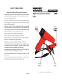
SAFETY PRECAUTIONS
—Read All Instructions Before Using The Analyzer—
Always wear eye protection when testing vehicles. Be extra careful
near batteries and moving parts. Do not lay tools on a battery.
Battery gas is highly explosive.
If a battery explodes flush the acid away from skin with generous
amounts of water. Follow up with a neutralizing solution of baking
soda and then more water.
Never use a wrench on the ungrounded battery terminal until
the grounded one has been disconnected. Contact between the
vehicle body metal and the hot terminal can cause sparks to ignite
gas or even weld tools into a battery short circuit.
Keep the space around a battery well ventilated.
Do not make sparks or allow flames near batteries.
Before working on a vehicle set the brakes and block the wheels.
Beware of automatic parking brake releases.
Keep your work area well ventilated and free of exhaust.
Avoid electrical shocks caused by getting close to live ignition wires
or touching the coil TACH terminal. A personʼs reaction near a
live engine can be more damaging than the shock.
Keep spark producing devices at least 0.5m (18”) above the floor
to reduce the hazard of igniting gasoline vapor.
Do not let test leads wind up in a moving fan or pulley. Route
leads away.
Remove finger rings and metal wrist bands. They can short
terminals and become very hot from electric current.
OPERATORʼS MANUAL
Digital Tach-Advance Timing
Light
Inductive Spark
Pickup
Mode
Button
Advance
Buttons
© Copyright 2005, GxT, Inc., All Rights Reserved
E088-01G
88
Power
Leads
Introduction
The Ferret 88 is a Dual Display Tach-Advance Timing Light. Both RPM and
advance can be read at the same time. The Ferret 88 also includes a Strobe
function which will allow you to measure the RPM of any rotating device.
Operating Specifications
Scale
Range
Advance (400-5,000 RPM)
to 90 degrees
Tachometer
400 to 9,990 rpm
Strobe RPM
400 to 5,000 rpm
Power Req.
10 to 16 Volts DC, 1.5 Amp
Resolution/Accuracy
0.5 degree ± 1 degree
10 rpm ± 1 %
10 rpm ± 1 %
12 volt battery
Temperature
Operating
0° to 122° F
Storage
-40° to 180° F
Weights & Dimensions
Leads
5 feet
Weight
1.7 pounds
Size
12 inches tip to tip, 2.8 wide
-18° to 50° C
-40° to 80° C
1.5 meter
770 gram
30 x 7 cm
FERRET BRAND LIMITED PRODUCT WARRANTY
GxT, Inc. of Cheboygan Michigan, warrants to the original purchaser that
FERRET brand products are free from defects in materials and workmanship for a period of two years from date of purchase. Our sole obligation
for a product within the above warranties will be to repair or replace,
at our option, any defective parts and return the product to the sender
within the U.S.A., shipping prepaid, if it is sent to our Repair Department
shipping prepaid and accompanied by proof of purchase.
This Warranty does not apply to products which have been altered
outside the factory; or repaired by anyone other than the factory or its
authorized service centers; or which have been damaged from accidents,
negligence, or abuse; or have been used differently than described in
the printed instructions. Please note that wear and tear on leads and
replacement of consumable items such as: NOx Sensors, Oxygen Sensors, and paper, is not covered by warranty.
Timing-Advance Test Procedure
GxT Inc.ʼs sole liability and buyerʼs exclusive remedy is limited to repair
or replacement of the product as stated in the Limited Product Warranty.
THERE ARE NO OTHER WARRANTIES EXPRESSED OR IMPLIED
INCLUDING THOSE OF MERCHANTABILITY OR FITNESS FOR A
PARTICULAR PURPOSE AND GxT, INC. SHALL NOT BE LIABLE FOR
INCIDENTAL OR CONSEQUENTIAL DAMAGES ARISING FROM THE
SALE OR USE OF THE PRODUCT.
1. Connect the power leads: RED - positive, BLACK - negative. Push the
Mode Select button to select 2 or 4 stroke operation. Place the Inductive
Pickup around the #1 spark plug wire.
Some states do not allow limitations on the length of implied warranties
nor exclusion or limitations of incidental or consequential damages, so
that the above limitations and/or exclusion may not apply to you.
This light measures advance by delaying the flash so that it appears to align the
crank shaft TDC mark to its pointer, and then displaying the degrees delayed.
Note that on engines with ignition contact points, dwell affects timing and must
be in calibration before timing is adjusted.
2. Prepare the engine for timing tests, such as: warming-up, disabling electric
and vacuum control lines, and cleaning the wheel timing marks. Then run
the engine. The light should begin flashing.
3. Read RPM, and set the engine speed to the test specification.
4. Point the light beam onto the degree marks at the engine damper wheel or
flywheel, and move the apparent mark to the TDC position using the Timing
Advance Control Buttons. Then read the timing advance on the display.
NOTE: Align your eye squarely with the timing marks when viewing, to
avoid parallax error.
5. Compare the measurement with the specification. Adjustments are made
by turning the distributor slightly or by moving the ignition timing sensor.
6. Restore all engine parts to their normal arrangement.
This warranty gives you specific legal rights and you may also have other
rights which may vary from state to state.
Inductive Pickup
around Spark Wire
Red
Black
Timing Marks
12 Volt
Battery
Timing Advance
Control Buttons
Initial Timing Measurement
Follow the engine service manual procedure or the emission control label in the
engine compartment. Not all engines can be adjusted. For engines with fixed
timing, you can determine the operational status of the timing system.
Vacuum Advance or Retard Measurement
Vacuum actuators connected to the distributor or intake manifold sensors vary
the timing according to engine vacuum. To measure, disconnect and plug the
input hoses and then couple the input to a hand pump with gauge. Run the
engine at idle to see the timing change with and without applied vacuum.
Centrifugal Advance Measurement
Mechanical ignition controls usually have a set of spinning weights in the
distributor which advance the spark timing a certain number of degrees as RPM
goes from idle to driving range. To see the centrifugal advance alone, vacuum
actuators must be disabled. Besides the amount of change, it is important to see
that the advance changes smoothly with slowly increasing RPM. Sticky weight
pivots, rust, and bad retracting springs are the usual problems.
Total Advance Measurement
This is the advance at a specified RPM with the engine timing controls intact.
Coil Wire Timing
Use only when required by engine specifications. Be sure to set advance to
zero, because the location of the mark will otherwise be affected by the number
of cylinders.
Strobe Light Measurements
Technical Support
1. Connect the power leads: RED - positive, BLACK - negative. Push the
Mode Select button to select strobe operation.
Include a note describing the problem.
The Strobe function on the Ferret 88 does not require the use of the inductive
spark pickup. You can use the strobe function to determine the RPM of any
rotating device.
2. Point the light beam at a rotating device.
3. Use the trigger button to increase or decrease the rate of the strobe flash
4. Begin increasing the flash rate of the strobe until you see a stopped motion
view of the rotating device.
5. Read the RPM of the rotating device on the back of the timing light.
Start at the lowest RPM available in the strobe function and increase the rate
until you see a single image that has been “stopped” by the light.
For example, if you are flashing the strobe light at a device that has 3 distinct
fan blades, you will see multiple blades stopped by the strobe. Continue
increasing the rate of the strobe until you see just 3 blades. This will be your
correct RPM.
Maintenance & Service
When cleaning the timing light, use a cloth dampened with waterless hand
cleaner. DO NOT use solvents such as acetone and benzene which can be
absorbed by and damage plastics. Promptly remove penetrating oils, gasoline,
and battery acid.
The Inductive Spark Pickup is a plug-in replaceable lead. It can be repaired or
replaced if damaged. Leave the Pickup latch Open when not in use. The
magnetic cores are made of ferrite ceramic and, when kept apart, they are less
likely to break if the pickup is dropped.
There are no user serviceable parts inside the timing light. Contact your tool
dealer or consult other materials packed with the light for repair information.
Electrical Interference
In the event that the unit is subjected to extreme electromagnetic conditions
the display may appear to lock up. Simply disconnect the power lead and
reconnect to reset the unit.
Questions or inquiries about service can be answered by contacting GxT, Inc.,
at: Toll Free (800) 627-5655. Fax: (231) 627-2727, Toll Free (231) 782-0616,
or [email protected]. When sending an item to the factory address it to:
GxT, Inc., 520 MM Riggs Drive., Cheboygan, MI 49721-1061
Replacement Parts
X008-01
X006-81
E088-01
Inductive Spark Pickup
Storage Case
Instruction Manual
Optional Ferret 765 Diesel Pulse Adapter
PIEZO CLAMP
Clamps around a 1/4” (6.35mm) fuel line, senses the pulse of fuel to #1 Cylinder,
and triggers the timing light or engine analyzer.
DIRECT CONNECTION
Eliminates confusion and increases accuracy by
directly connecting to the test instrument in place
of the Spark Pickup
INDICATOR LIGHT
Flashes when a signal is detected from the Piezo
Clamp.
9V BATTERY POWERED
Internal 9 volt battery eliminates the need for power
leads.
ENGINE COMPATIBILITY
Works on most Diesel engines with 1/4” external fuel lines.