1
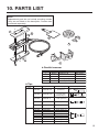
® PARALLEL REMOVER Instruction Manual ● Thank you for purchasing the FM-2022 parallel remover. Please read this manual before operating the FM-2022. Keep this manual readily accessible for reference. ● CAUTION • The FM-2022 cannot function by itself. It must be connected to an FM-202 soldering station. • Specific information can be found in the instruction manual for your FM-202 soldering station. TABLE OF CONTENTS 1. PACKING LIST .........................................................1 2. SPECIFICATIONS ....................................................1 3. WARNINGS, CAUTIONS AND NOTES ...................2 4. PART NAMES...........................................................3 5. SETTING UP THE FM-2022 ....................................3 6. OPERATION.............................................................4 7. TIP IDENTIFICATION NUMBER ..............................6 8. MAINTENANCE .......................................................7 9. TROUBLESHOOTING GUIDE .................................8 10. PARTS LIST ...........................................................10 11. WIRING DIAGRAM ................................................11 1. PACKING LIST Parallel remover ..................................... 1 Heat resistant pad .................................. 1 Tip (not included) Heat resistant pad MODEL FM-2022 Parallel remover Cleaning sponge Holder clip ● Applicable Models In order to function, the FM-2022 must be connected to the FM-202 soldering station. 2. SPECIFICATIONS MODEL FM-2022 Parallel remover Power Consumption Temperature Range Tip to Ground Resistance Tip to Ground Potential Cord Assembly Total Length (w/o cord) Weight (w/o cord) 140W (24V) 200 – 400°C (400 – 750°F) < 2Ω < 2mV (typical 0.6mV) 1.2m (4 ft.) 110mm (w/o tip) 53g (Parallel remover only) 11g (SOP 25L Tip only) ∗ Specifications and design are subject to change without notice. 1 3. WARNINGS, CAUTIONS AND NOTES Warnings, cautions and notes are placed at critical points in this manual to direct the operatorʼs attention to significant items. They are defined as follows: WARNING: Failure to comply with a WARNING may result in injury or death. CAUTION: Failure to comply with a CAUTION may result in injury to the operator, or damage to the items involved. (One example is given below.) NOTE: A NOTE indicates a procedure or point that is important to the process being described. CAUTION When the power is on, the tip temperature is between 200°C/400°F and 400°C/750°F. Since mishandling may lead to burns or fire, be sure to comply with the following precautions: ● Do not touch the metal parts near the tip. ● Do not use the product near flammable items. ● Advise other people in the work area that the unit can reach a very high temperature and should be considered potentially dangerous. ● Turn off the power while taking breaks and when finished using the unit. ● Before replacing parts or storing the unit, turn off the power and allow the unit to cool to room temperature. CAUTION To prevent damage to the unit and ensure a safe working environment, be sure to comply with the following precautions: ● Do not use the unit for applications other than those specifically described in the instruction manual. ● Do not set the tip temperature higher than 400°C/750°F. ● Do not rap the FM-2022 against the work bench to shake off residual solder, or otherwise subject the iron to severe shocks. ● Do not modify the unit. ● Use only genuine HAKKO replacement parts. ● Do not wet the unit or use the unit when your hands are wet. ● The operating process will produce smoke. Make sure the area is well ventilated. ● Pull on the plug to disconnect the FM-2022 from the station outlet. Do not pull the cord. 2 4. PART NAMES LED Button Fixing flange Handle Tip (not included) Cord Cleaning sponge Tip ID Plug Plug Holder clip Heat resistant pad 5. SETTING UP THE FM-2022 1. Connector cord Pass the connector cord through the hole in the heat resistant pad. 2. Iron holder (Optional, part no. FH100-01 or FH100-02) Attach the holder clip to the iron holder no.FH100-01 or FH100-02. Before tightening the screw, make sure that the two projections of the holder clip are touching the upper wire of the iron holder. Upper wire Two projections No.1 No.2 3. Connections 1. Connect the plug to the FM-202. 2. Place the FM-2022 in the iron holder. 3. Plug the power cord into the power supply. Be sure to ground the unit. NOTE: This product is protected against electrostatic discharge and must be grounded for full efficiency. 3 When the plug clicks , it is fully inserted. Receptacle Push the plug in as far as it will go, and try to remove it without pressing the release pin. If it stays in the receptacle it is properly seated. 6. OPERATION ● Controls and displays Please refer to the FM-202 instruction manual. NOTE: If the buzzer sounds three times when the tip is inserted into the process gate, there has been a reading error. Reinsert the tip. If the Tip ID is torn or damaged the process gate will not be able to read it. See the FM-202 manual for instructions on manually entering the Tip ID. MODEL FM-202 Soldering station Receptacle Process gate CAUTION: Refrain from inserting foreign objects, the wrong end of the tip, or incompatible tips into the process gate. Damage may result. NOTE: This procedure must be followed EVERY TIME THE STATION IS TURNED ON. ● Displays 1. If tips are in the handpiece, remove them. 2. Turn the power switch ON. and the 3. The display will show LED on the connector will flash. 4. Enter Tip ID as follows: Insert the Tip ID end of one of the tips into the process gate until the buzzer sounds once. Tip ID data are displayed for one second. The display shows Display Turn the switch ON. TIN error Setting temperature and LED lamp at the connector begins to flash. . NOTE: The tips are a set of 2 pieces with the same Tip ID. They must be used together. 5. Inserting the tip: Hold the head part of the tip with the heat resistant pad and insert the tip into the handpiece. Push until the tip stops. Repeat for second tip. There is a flange. Make sure that the flange will fit the handle when inserted into the handpiece. 4 6. When the set temperature is reached, the buzzer sounds and the heater lamp at the lower right of the temperature display starts blinking. NOTE: Once the two tips are inserted into the handpiece, heat control begins. Both tips of the set must be inserted or the handpiece will not heat. ● Operating instructions 1. Set the Temperature CAUTION: Never set the temperature to any value over 400°C (750°F). Doing so may damage the station. Set the temperature according to the type of work to be done. 2. Apply solder or flux If there is insufficient solder on the PWB, or the soldered area is too small, apply solder or flux to the PWB. Solder may also be applied to the tip. CAUTION: The tip is very hot during operation. Do not touch the tip or the metal parts near the tip. CAUTION: Very high tip temperatures may damage the printed circuit board, possibly causing the printed pattern to become detached. HAKKO recommends setting the tip temperature below 300°C (572°F) for all normal work. Using the lowest possible effective temperature not only helps protect parts that are sensitive to heat, it also helps protect the tip from deterioration caused by heat. 3. Melt the solder Place the tip on the soldered part and melt the solder. Confirm that the solder is fully melted. See sketch “A”. Solder A 4. Remove the component After confirming that the solder is fully melted, lightly squeeze the handpiece to grasp the component and lift to remove the component. See sketch “B”. 5 B Component ● Control card and changing the temperature setting Please refer to the FM-202 Instruction manual. ● Replacing the tip Removing and inserting the tip: Removing the tip: Hold the handle and pull the tip out of the handpiece with the heat resistant pad. Inserting the tip: Before inserting the tip; Insert the Tip ID end of the tip into the process gate until the buzzer sounds once. Hold head part and insert the tip into the handpiece. Push until the tip stops. Hold this part to insert into the tweezer. Hold the tweezer at the front to remove tip. CAUTION: The tip can be very HOT. Use the heat resistant pad for handling hot tips, but do not hold the hot portion of the tip, even with the pad, for longer than necessary. 7. TIP IDENTIFICATION NUMBER Please refer to the FM-202 Instruction manual. 6 8. MAINTENANCE ● Tip maintenance Please refer to the FM-202 Instruction manual. ● Checking Procedure WARNING: Unless otherwise directed, carry out these procedures with the power switch OFF and the power UNPLUGGED. ■ Verify the electrical integrity of the heater and sensor 1. Check for a broken heater or sensor Measure the resistance across this position Tip ID Measure the resistance across the tip as shown. Measure the resistance while at room temperature(15 to 25°C; 59 to 77°F). It should be 8Ω± 10%. If the resistance exceeds these limits, replace the tip. ■ Check the grounding line 5 3 7 2 8 4 1 6 ■ Checking the connection cord for breakage (Refer to P.11 WIRING DIAGRAM of B side.) B side socket Green Black Red 7 White (inside) 1. Unplug the connection cord from the station. 2. Measure the resistance value between pin 2 and the tip (both tips). 3. If the value exceeds 2Ω (at room temperature), perform the tip maintenance described on P.12 of the FM-202 instruction manual. If the value still does not decrease, check the connection cord for breakage. 1. Remove the soldering tip and the handle. 2. Measure the resistance values between the connector and the lead wires at the socket as follows: Pin 1 - Red Pin 2 - Green Pin 3 - Black Pin 5 - White If any value exceeds 0Ω or is ∞, replace the FM-2022. ■ Checking the connection cord for breakage (Refer to P.11 WIRING DIAGRAM of A side. ) A side socket (3) (4) (1) (2)(inside) 1. Remove the soldering tip and the handle. 2. Measure the resistance values between the connector and the lead wires at the socket as follows: Pin 7 - (1) Pin 2 - (3) Pin 4 - (4) Pin 8 - (2) If any value exceeds 0Ω or is ∞, replace the FM-2022. 9. TROUBLESHOOTING GUIDE WARNING: Disconnect the power plug before servicing. Failure to do so may result in electric shock. ● The tip does not heat up. CHECK ACTION CHECK ACTION CHECK : : : : : ● Solder does not wet the tip. CHECK ACTION CHECK ACTION : : : : ● The tip temperature is too high. CHECK : Is the connection cord broken? ACTION : See “Checking the connection cord for breakage”. CHECK : Is the entered tip identification number correct? ACTION : Enter the correct value. • The sensor error played. is dis- Is the power cord disconnected? Connect it. Is the tip inserted properly? Insert the tip completely. Is the connection cord and/or the heater/sensor broken? ACTION : See the appropriate section of this manual regarding how to check the connection cord and/or the heater/ sensor for breakage. Is the tip temperature too high? Set the appropriate temperature. Is the tip contaminated with oxide? Remove the oxide by cleaning the tip on a damp sponge of Hakko 599B tip cleaner. 8 ● The tip temperature is too low. CHECK : Is the tip contaminated with oxide? ACTION : Remove the oxide by cleaning the tip on a damp sponge of Hakko 599B tip cleaner. CHECK : Is the entered tip identification number correct? ACTION : Enter the correct value. ● The soldering iron error is displayed. CHECK : Is the connection cord broken? ACTION : See “Checking the connection cord for breakage”. CHECK : Is the FM-2022 plug disconnected? ACTION : Connect the FM-2022. ● The low-temperature alarm tolerance error occurs frequently. CHECK : Is the tip too small for the items to be removed? ACTION : Use a tip with a large thermal capacity. CHECK : Is the setting value for the low-temperature alarm tolerance too low? ACTION : Increase the setting value. is dis- CHECK : Does the tip come off during use? ACTION : Enter correctly. See section 6, Operation for instructions. ● Tip ID error played. NOTE: If the buzzer sounds three times when the tip is inserted into the process gate, there has been a reading error. Reinsert the tip. If the Tip ID has been torn or damaged the process gate will not be able to read it. See the FM-202 manual for instructions of manually entering the Tip ID. ● Heater terminal short circuit error is displayed. CHECK : Is the tip for FM-2022? ACTION : Turn the power switch OFF and insert the correct FM-2022 tip. Turn the power switch ON. NOTE: This error does not display when not entering the Tip ID. ● The tips cannot be closed. 9 • The tips will not return to the original position. CHECK : Is there a foreign object between the tips? ACTION : Remove it. 10. PARTS LIST NOTE: Replacement parts do not include mounting screws if they are not listed on the description. Screws must be ordered separately. 1 A 2 3 4 B 5 Parallel remover Item No. 1 2 3 4 5 Tips CHIP SOP Part No. Part No. B2783 B2784 B2300 A1519 B2850 Part Name Handle A & B LED Holder Heat resistant pad Cleaning sponge Holder clip Part Name Size A [a] T8-1001 Tip/CHIP 0.5I R0.2 mm (0.008 in.) A T8-1002 Tip/CHIP 0.5C 1.5 [0.5] mm (0.06 [0.02] in.) A T8-1003 Tip/CHIP 1L 1 mm (0.04 in.) T8-1004 Tip/CHIP 2L 2 mm (0.08 in.) T8-1013 Tip/CHIP 3L 3 mm (0.12 in.) T8-1005 T8-1006 T8-1007 T8-1008 T8-1009 T8-1010 T8-1011 T8-1012 Tip/SOP 6L Tip/SOP 8L Tip/SOP 10L Tip/SOP 13L Tip/SOP 16L Tip/SOP 20L Tip/SOP 25L Tip/SOP 18L 6 mm (0.24 in.) 8 mm (0.31 in.) 10 mm (0.39 in.) 13 mm (0.51 in.) 16 mm (0.63 in.) 20 mm (0.79 in.) 25 mm (0.98 in.) 18 mm (0.71 in.) Specifications With screws With screw Shape a A A 10 11. WIRING DIAGRAM A side socket 1 2 3 + – S LED1 P.W.B./LED B side socket 1 2 3 Purple Blue Brown Yellow R1 Green Black Red White HEAD OFFICE 4-5, SHIOKUSA 2-CHOME, NANIWA-KU, OSAKA, 556-0024 JAPAN TEL:+81-6-6561-3225 FAX:+81-6-6561-8466 http://www.hakko.com AMERICAN HAKKO PRODUCTS, INC. 28920 N. AVENUE WILLIAMS VALENCIA CA 91355, U.S.A. TEL: (661) 294-0090 FAX: (661) 294-0096 Toll Free (800)88-HAKKO www.hakkousa.com 4 2 5 5 6 Copyright © 2005 HAKKO Corporation. All Rights Reserved. 11 2005.10 MA01173JZ051013


![Instruction Manual - [HAKKO] Document Portal](http://vs1.manualzilla.com/store/data/005882531_1-c17999a04ed3b96f12c2eb288800f74b-150x150.png)