1
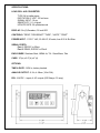
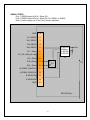
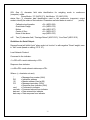
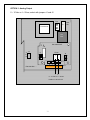
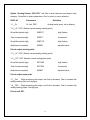
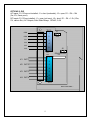
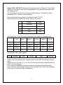
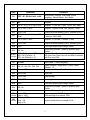
Emery Winslow Scale Company
73 Cogwheel Lane
Seymour, CT 06483
(203) 881-9333
(203) 881-9477 FAX
4530 North 25th Street
Terre Haute, IN 47805
(812) 466-5265
(812) 466-1046 FAX
INSTRUCTION & SERVICE MANUAL
7400E Digital Indicator
V1.96
TABLE OF CONTENTS
SPECIFICATIONS………………………………………3
INSTALLATION…………………………………………4
SETUP ACCESS………………………………………..5
MENU LAYOUT...………………………………………6
CONFIGURATION……………………………………..7
REMOTE SERIAL DISPLAY………………………….8
CALIBRATION………………………………………….9
SERIAL PORTS………………………………………10
SERIAL COMMUNICATIONS……………………….11
ANALOG OUTPUT……………………………………13
DIGITAL INPUT/OUTPUT……………………………15
SETPOINTS……………………………………………17
OVER/UNDER…………………………………………17
BATCH MODE…………………………………………18
TIME & DATE………………………………………….19
AC/DC OPERATION………………………………….19
DISPLAY MESSAGES………………………………..20
115/220 VAC…………………………………………..21
SPARE PARTS………………………………………..22
2
SPECIFICATIONS:
LOAD CELL A/D CONVERTER
TYPE: 24 bit delta sigma
EXCITATION: 5 VDC, 120 mA max.
SIGNAL INPUT: 16 mv
SENSITIVITY: 0.1 uV/grad
UPDATE RATE: 30 update/second
DISPLAY: Six (6) Decades, 0.6 inch LED
CONTROLS: "ZERO","GROSS/NET","TARE", “UNITS”, "PRINT"
POWER INPUT: 117/217 VAC, 50-60 HZ, 20 watts, fuse 0.25 A Slo-Blow.
SERIAL PORTS:
Port 1: RS232C or 20ma
Port 2: RS485, RS232C or 20mA.
ENCLOSURE: Stainless Steel, NEMA 4x, Tilt - Stand Base, 7lbs.
CASE: 10”(w) x 6.5”(h) x 4”(d)
OPTIONS:
TIME & DATE: 12/24 hr, battery backed.
ANALOG OUTPUT: 0-10v, 4-20ma (16 bit D/A).
DIO: 4 AC/DC – inputs, 4 AC outputs (SS Relays, 0.5 amp)
3
INSTALLATION
POWER WIRING:The indicator is designed to be operated from 117/217 VAC, 50-60 Hz. The
unit power cord must be plugged into a grounded 3 - wire polarized AC wall socket. All normal
wiring and grounding precautions should be observed, including use of a "clean" AC power
line.
SCALE WIRING:The unit is equipped with cable gland entry for load cell cable insertion and
internal (pluggable) terminal strip for 4 / 6 wire connection. Remove sense jumpers P11-8/7,
P11-6/5 for six wire.
P12
F1
Transformer
0.25A
SB
Line
Filter
Shielded
A/D Converter
12
A
J1
B
SW4
P5
8 7
6
EW-1000 Rev…..
Excitation +
Sense +
Excitation –
Sense -
5
6 5
4
CAL
P11
3
2
1
TB-1
Signal +
Signal -
4
Keypad:
ZERO
GROSS
NET
TARE
UNITS
PRINT
SETUP ACCESS
To access instrument configuration, calibration or to enable options, depress the “Zero” key for
five seconds.
The Audit Trail counters (“Pxxxx” and “Cxxxx”) are displayed first followed by access code
request (“AC?”). The initial factory setting is “0000” which can be entered with four steps of the
“Gross/Net” key (“AC0000”) and “Print”. If no entry is made, instrument returns to operate
mode.
The access code can be changed to any four digit combination during setup exit when display
again shows “AC?”. Use the Tare key to increment a digit and Gross/Net to shift the digit
position.
The display check feature is accessed during the initial entry point “AC?”, by a second step of
the “Zero” key. The software version “V 1.XX” will be displayed followed by a continuous
display test routine. Another step on the “zero” key returns to “AC?”.
Front panel access is inhibited if conventional “sealing” is applied by
setting jumper J1-1 in the B position. The board mounted “CAL” button is
then used for access.
After entry, use the “Gross/net” key to select a main menu; configuration (“SEL.CFG”),
calibration (“SEL.CAL”), or options (“SEL.OPX”).
The “Zero” key enters selected menu and is used to step through sub categories. Individual
parameter selection is made with the “Gross/Net” key, which then steps through the parameter
choices.
The “Print” key is used at any point to “back” up from categories to menus and to “save?” and
“AC?” and exit.
During the exit steps, if changes were made, the display is “save?” with alternate “no”. To save
changes, use the “Tare” key to select “yes” and “Print” to exit.
Calibration numeric entries are made with “Tare” key incrementing the flashing digit and the
“Gross/Net” key shifting the digit selection.
5
Menu Layout
CFG
Configuration: Divisions, count by, decimal, over
range, filter, AZM, zero range, ISM, lb/kg, serial port
selection, DIO enable
CAL
Calibration: Zero, Span
OP1
Analog Output: Gross, Net, Display; Zero, Span, Trim
OP2
Setpoint DIO: Setpoint, Over/Under, Manual / Auto Batch
OP3
Time & Date: 24 hr, 12 hr, Print format
OP5
10 Point Linearity, Filter selection
OP6
Totalizer
OP8
AC/DC Battery
6
CONFIGURATION: “SEL.CFG” Use Zero to enter the menu and step to each category,
Gross/Net to select parameters. Print to return to menu selection.
Capacity is the combination of “1”, “2” and “3”.
Example: 1__100, 2___2 and 3__0.0 = 2,000 x 0.2 lb
Step
Parameters
Definition
Number of divisions x100
100 = 10,000 divisions
Count by selection
10,000 divisions, count by 2 = 20,000
1
5, 10, 15, 20…100, 120…1000
2
1, 2, 5, 10, 20, 50, and 100.
3
0, 0.0, 0.00, 0.000, and 0.0000
Decimal point selection
4
105P, 9 d (105% or 9 divisions)
Overrange selection
5
1, 2, 3, 4, 5, 6, 8, 10, 12, 15…..90
Digital filter selection (averaging)
6
off, 0.5, 1, 3, 5, 10 (divisions)
Auto Zero Maintenance (AZM)
7
1.9, 5, 10, 20, FS (% of capacity)
Zero range selection
1.9% of 2,000 x 0.2 = 38.0 lb
7.1
off, on (ISM)
Zero’s scale on power-up
8
off, 1, 3, 5,10 (divisions)
Motion Band selection
9
lb, kg, con
Units selection and convert
10
nt, Gtn, n.nt, n.Gtn.
Port 1 serial output selection
nt display only, Gtn is Gross Tare Net
and n.nt/n.Gtn inhibit neg gross print
11
off, co, de
Off, Continuous, or Demand
12
7o, 7E, 8n
7- odd, 7- even or 8- none
13
12, 24, 48, 96
Baud rate selection
14
off, 1, 2, 3, 5, 10, 15 (seconds)
19
A, b
20
nt, Gtn, n.nt, n.Gtn
Port 2 serial output selection
21
off, co, de, Ln
Off, Continuous, Demand, Network
22
7o, 7E, 8n
7- odd, 7- even or 8- none
23
12, 24, 48, 96
Baud rate selection
24
off, 1, 2, 3, 5, 10, 15 (seconds)
Delay between lines or continuous
output.
25
1 – 16 (RS485/RS422)
Network address selection
30
off, on
DIO Inputs
Delay between lines or continuous
output.
A : adds “STX” in continuous
b : No “STX” in continuous
7
Remote Serial Display (RSD) Option
In RSD mode the instrument can be set to work with another unit as a “remote” either as the
main or the slave unit. Communication is pre-set for channel two only on both units.
(RS232, 9600, 8, none)
When in remote mode, re-access to the following selections requires using the internal “cal”
switch.
Remote unit can have full or partial control of the main unit. Devices are available to replace
the cable for wireless communication.
40
rd.OF, rd.En, rd.re
rd.En : Selects Indicator as Remote
Display (RSD)
rd.re : Allows indicator to operate
w/RSD
41
En.On
Allow remote keypad operation
42
Zr.On
Enable/Disable zero key
43
tr.On
Enable/Disable tare key
44
Un.On
Enable/Disable unit key
45
Pr.On
Enable/Disable print key
46
Fn.On
Enable/Disable all other functions
8
CALIBRATION: “SEL.CAL” Use Zero to enter the menu indicated by a flashing “C” on the left
and live weight is displayed. Scale zero (dead load) or adjusting span (single or multi-point) are
independent. Therefore either can be done and repeated as necessary before exiting
calibration. If an error has been made, exit without “storing” will return to prior setup.
KEY (FUNCTION)
DISPLAY
Definition
(Live weight 123 lb)
“C”__123
Cal mode scale reading
Zero (acquire dead load)
“------“ to “C___0.0”
acquires new dead load
(live weight 5000 lb)
“C”__4995
Scale reading with load
Gross/Net (adjust span)
004995
Gross/Net (select digit)
00499”5”
digit flashes
Tare (increments digit)
00499”0”
Increments
Gross/Net (select digit)
0049”9”0
digit flashes
(Adjustment complete)
005000
adjusted value
freezes display for adjustment
Then with Print:
(adjust span)
“------“ to “C” 5000
displays new span
Repeat as required then use Print to exit CAL.
“Save ?” “No” or “Save ?” “Yes” use Tare to select and Print to store “yes” with changes or
“no” to exit without changes.
Continue with Print to “Ent AC” which allows access code change by entering a new four digit
code and press again or skip with no entry.
Option 5 Ten point calibration: Allows up to 10 span points (pt1…….pt10). Zeroing the scale
clears the existing values. Points are assigned incrementally with error indication if the addition
is not above the prior point or exceeding scale capacity.
Filter selection included for rolling or box averaging.
5.1
OFF, On
Enable 10 point span
5.2
A, b
A : Rolling average
B : Box average
9
SERIAL PORTS
Port 1: RS232 duplex (Rx,Tx), 20ma (Tx).
Port 2: RS232 duplex (Rx,Tx), 20ma (Rx,Tx), RS485, or RS422.
Note: Position jumper on J2 for Port 2 receive selection.
GND
1
Tx1, RS232
2
Rx1, RS232
3
Tx2, RS232
4
Rx2, RS232
5
Tx1, -20ma
6
Tx1,Tx2,+20ma (5 vdc)
7
A-RS232
B-20ma
C-RS485
D-RS422
Tx2, -20ma
8
J2
Rx2,+20ma
9
Rx2, -20ma
10
B, RS485, RS422-Tx
11
A, RS485, RS422-Tx
12
B, RS422-Rx
13
A, RS422-Rx
14
GND
15
O1
EW-1000 Rev…
10
Rx2
Serial Communications
Remote Commands
<Z><cr>
Zero Scale
“Gross” mode, no motion, inside zero range.
<N><cr>
Switch to Net
“Gross” mode with Tare stored.
<G><cr>
Switch to Gross
“Net” mode.
<T><cr>
Auto Tare
Switch to Net, no motion, not at “Gross” zero.
<P><cr>
Print
Valid display, No motion
Data Formats
Demand Mode: <stx><pol><DATA><sp><lb/kg><sp><GR/NT><cr/lf>
Continuous Mode: <stx><pol><DATA><L/K><G/N><status><cr/lf>
Brackets “<>” are not sent
stx:
“Start of Text” character (ASCII 002) (can be removed in continuous: config 19)
pol:
Polarity sign, “SPACE” (ASCII 032) for positive or (-) sign (ASCII 045) for negative
sp:
Space character (ASCII 032)
DATA: Seven (7) digit data field including decimal point or fixed (dummy) zero if selected.
“Leading Zero Suppression” with leading zeros transmitted as “space” characters.
lb/kg: Two (2) character field data identification for weight units, in demand (printer) mode.
Weight in lb = “lb” (ASCII 108,098), weight in kg = “kg” (ASCII 107,103)
L/K: One (1) character field data identification for weight units in continuous (computer)
mode.
Weight in lb = “L” (ASCII 076), weight in kg = “K” (ASCII 075)
GR/NT: Two (2) character field data identification for weighing mode in demand (printer)
mode.
Gross Mode = “GR” (ASCII 071,082), Net Mode = “NT” (ASCII 078,084)
11
G/N: One (1) character field data identification for weighing mode in continuous
(computer) mode.
Gross Mode = “G” (ASCII 071), Net Mode = “N” (ASCII 078)
status: One (1) character data identification used in the continuous (computer) output
mode to identify the status of the indicator. Characters are listed below in order of
priority.
Calibration/configuration
Over/Under Range
Motion
Center of Zero
None of the above
cr/lf:
<D> (ASCII 068)
<O> (ASCII 079)
<M> (ASCII 077)
<C> (ASCII 067)
<sp>(ASCII 032)
Two (2) character field, “Carriage Return” (ASCII 013), “Line Feed” (ASCII 010)
Guidelines for Serial Output:
Demand format will inhibit “print” when scale is in “motion” or with negative “Gross” weight, even
in “Net” mode (based on setting “CFG 10”).
Local Network Protocol:
Command to the indicator:
<*><DD><00><cmd><data entry><CR>
Response from indicator:
<:><00><DD><cmd echoed><data resp><CR>
Where: (<,> brackets not sent)
*
= Message from master (2AH)
DD
= Indicators address
00
= Master address (fixed at 00)
CR
= Message terminator (ODH)
:
= Response from indicator (3AH)
cmd
= Command to indicator
cmd ech = Command echoed from indicator
data ent = Data entered into indicator
data resp = Data response from indicator
12
OPTION 1: Analog Output
0 – 10 Vdc or 4 – 20 ma, select with jumpers J1 and J2
P12
F1
Transformer
0.25A
SB
Line
Filter
EW-1000-AOUT
P5
12
A
J1
B
TB 20
J1
V
1
-
I
8 7
EW-1000 Rev…..
6
5
J2
V
2
+
I
6 5
4
P11
3
2
1
TB-1
- +
0 – 10 Vdc or 4 – 20 ma
Position J1 & J2 for V/I
13
Option 1 Analog Output: “SEL.OP1” Use Zero to enter the menu and step to each
category, Gross/Net to select parameters. Print to return to menu selection.
DISPLAY
Parameters
1.1__Gr
Gr, Net, DSP
Definition
Analog tracks gross, net or display
“1.5__Zr” “0.00” (flashes current analog starting point)
Gross/Net (select digit)
00000”0”
digit flashes
Tare (increments digit)
0000”5”
Increments
Gross/Net (select digit)
0000”2”5
digit flashes
(Adjustment complete)
000025
adjusted value
Print to adjust starting point.
“1.5__Zr” “0.25” (flashes current analog starting point)
“1.6__FS” “0.00” (flashes current analog span point)
Gross/Net (select digit)
00”0”000
digit flashes
Tare (increments digit)
00”5”000
Increments
(Adjustment complete)
005000
adjusted value
Print to adjust span point.
1.7__ZrA
While monitoring the output, use Unit to decrease, Tare to increase the
analog reading (Zero trim digi-pot).
1.8__FSA
While monitoring the output, use Unit to decrease, Tare to increase the
analog reading (Span Trim digi-pot).
Print to exit OP1.
14
OPTIONS 2: DIO
AC Inputs; D1, D2 are not installed, J1 = short (underside), J2 = open, R1 – R4 = 18k
(3w, 5%, flame proof).
DC Inputs; D1, D2 are installed, J1 = open (cut trace), J2 = short, R1 – R4 = 1.5k (1/2w,
5%, carbon film). AC Outputs; Solid State Relays, 120VAC, 0.5A
TB 30
COM
1
COM
2
IN 1
J1
3
IN 2
4
IN 3
5
IN 4
D1
D2
J2
EW-1000-DIO
P4
1
K1 OUT 1
2
3
K2 OUT 2
4
K3 OUT 3
5
6
K4 OUT 4
7
TB 31
EW-1000 Rev…
.
15
Option 2 DIO: “SEL.OP2” First select the operating mode for “Setpoint”, “Over/Under”,
“Manual or Auto Batch”. After setup, the parameters for the selection are entered from
the weighing mode.
Use Gross/Net to enter the menu and step to each category, Tare Recall to select
parameters. ENT to return to menu selection.
Note: external Inputs are enabled in Configuration with “CFG 30”.
DIO Inputs can be configured for 120vac, 5vdc or dry contact.
Normal
Batch
IN 1
Gross/Net
Stop
IN 2
Tare
Start
IN 3
Zero
Zero
IN 4
Print
Print
DIO Outputs are 120vac (0.5 amp) or optional 24 vdc, based on operating mode:
Dual
Setpt 1
Setpt 2
Ov/Un
Man B
Auto B
Out 1
Setpt1-A
Main 1
Main 1
Low
Main 1
Main 1
Out 2
Setpt1-B
Fast F1
Fast F1
Accept
Fast F1
Fast F1
Out 3
Setpt2-A
Tol
Main 2
High
Main 2
Main 2
Out 4
Setpt2-B
Zero B
Fast F2
Zero
Zero
Fast F2
Checkweigher “Bar” graph legends:
Ck1-3
Out Low
Low
Accept
High
Out High
Setpoint values are entered from “Weighing Mode” by the SET key and direct numeric
entry.
Weight errors of any kind (e.g., ol, ul, etc) will de-energize all relay outputs and abort a
batch if one is in progress.
Four outputs are available to use as two setpoints with main and fast feed, single
setpoint main and fast feed plus tolerance and zero band. Also Pre-Act can be applied
to the main, for material in-flight compensation.
16
Step
Parameter
Definition
Mode select: setpoint, over/under (check
weighing), Manual Batch, Auto Batch
2.0
OFF, SP, OU.UN, bAt1, bAt2
2.0
SP
Setpoint
2.2
Off, s1, s1.p, s1.d, s.p.d, Dual
Setpoint. 1 + pre-act, + drib, + both, Set1-A&B.
2.3
Gr, nt, dSP, Count
Setpoint 1 tracks Gross, Net, Display, Count
2.4
POS, ZER
Output on below reading (POS), inverted (ZER)
2.6
Off, s2, s2.p, s2.d, s2.p.d, tOL,
Dual
Setpoint. 2 + pre-act, + dribble, + both,
Tolerance, Set2-A&B.
2.7
Gr, nt, dSP, Count
Setpoint. 2 + pre-act, + dribble, + both
2.8
POS, ZER
Output on below reading (POS), inverted (ZER)
2.10
ZbO
Zero band output (input weight value)
2.11
Off, On
SP1.trG (Target) = 1000
SP1.PrE (Pre-act) = 5
example
SP1.drb (Dribble) = 10
s.p.d
Hysteresis, provides 3 grads to prevent relay
chatter
Main and Fast Feed are on until reading reaches
990, then Fast Feed turns off and Main continues
until Pre-act at 995
2.0
OU.UN
Over/Under – check weighing
2.2
Off, HL, tGt, Ck1, Ck2, Ck3
High/Low band, Target and +/- band, Check
Weigher 1-3.
2.3
Gr, net, dSP
Outputs track Gross, Net, Display
2.4
POS, ZER
Invert low
2.5
POS, ZER
Invert accept
2.6
POS, ZER
Invert high
2.10
ZbO
Zero band output (input weight value)
2.11
Off, On
Hysteresis, provides 3 grads to prevent relay
chatter
2.12
Off, On
Enables “Bar” graph legends
Low = 950
High = 1050
Target = 1000
tGt
Low = 50
example
High = 50
HL
example
Then low is on until 950, then accept is on until
1050 and high is on above 1050.
Outputs match above example for HL
17
Note:
Batch printouts are from Port 1
only
Bat 1
Manual Batch mode, pauses between setpoints
2.1
Prn, tAr, dln
7400 uses print, tare or external (DIO) for start.
Pressing any key other than “start” will pause and
a second push will abort. 7600E uses Start/Stop
panel switch
2.2
Off, s1, s1.p, s1.d, s.p.d
Setpoint. 1 + pre-act, + dribble, + both
2.3
Gr, nt, dSP, Count
Setpoint 1 tracks Gross, Net, Display, Count
2.4
POS, ZER
Output on below reading (POS), inverted (ZER)
2.6
Off, s2, s2.p, s2.d, s2.p.d
Setpoint. 2 + pre-act, + dribble, + both
2.7
Gr, nt, dSP, Count
Setpoint. 2 + pre-act, + dribble, + both
2.8
POS, ZER
Output on below reading (POS), inverted (ZER)
2.10
ZbO
Zero band output (input weight value), available if
S2 dribble not used
2.0
Bat 2
Auto Batch mode, continues without pause
2.1
Prn, tAr, dln
7400 uses print, tare or external (DIO) for start.
Pressing any key other than “start” will pause and
a second push will abort. 7600E uses Start/Stop
panel switch
2.2
Off, s1, s1.p, s1.d, s.p.d
Setpoint. 1 + pre-act, + dribble, + both
2.3
Gr, nt, dSP, Count
Setpoint 1 tracks Gross, Net, Display, Count
2.4
POS, ZER
Output on below reading (POS), inverted (ZER)
2.5
Off, 1, 2, 3, …., 10
Time Delay (settling) before print
2.6
Off, s2, s2.p, s2.d, s2.p.d
Setpoint. 2 + pre-act, + dribble, + both
2.7
Gr, nt, dSP, Count
Setpoint. 2 + pre-act, + dribble, + both
2.8
POS, ZER
Output on below reading (POS), inverted (ZER)
2.9
Off, 1, 2, 3, …., 10
Time Delay (settling) before print
2.10
ZbO
Zero band output (input weight value), available if
S2 dribble not used
2.0
18
OP3
Time & Date
3.1
---, 24H, 12A, 12P
Skip time, 24 hour, 12 hour am, 12 hour pm
3.2
T1
Set time: hh mm ss
3.3
dA
Set date: mm dd yy
3.4
S.no, no, Let
Month print selection, short numerical
(mm/dd/yy), number 01 thru 12, month spelled
out
3.5
Off, Un, Ab, On
Print under, above or on the same line
OP5
10 Point Linearity
On, Off see page 8
OP6
Totalizer
6.1
Off, On
Enable Totalizer (operates with Batch or Print)
6.2
Off, 1……50
Totalizer reset band
Option 6 Totalizer: Operates with “print” function in normal mode or batch mode.
In normal mode, current value is added to the totalizer with each “Print” command. The
reset band is used to inhibit a double add when not in Batch Mode.
View the Total with the “2” key and during the display (AC..XXXX), the “Print” key is
used to print the total, the “Ent” key returns to weigh mode.
The “Clear” key is used to clear the totalizer by first changing the message from
“Clr.ACC…no” to “Clr.ACC…yes” with the “Units” key and “Ent” to complete. A
“Cleared” message is provided for conformation.
Note: Totalizer works with port 1 only and the “Print” key is disabled when Batch Mode
and Totalizer are both enabled.
Option 8: AC/DC operation
8.1
Off, On
Enables battery charger
8.2
Off, 5, 15, 30, 90, 120
Auto shutoff in minutes, timer resets with motion
19
DISPLAY MESSAGES
MESSAGE
DAC
IIC.ERR
RST
ON
AUTO
ERR6.x
-232UPDATE
LO.BATT
D BATT
ULULUL
OLOLOL
-----7x00
Err 10
Err 13
ADC.Err
CHECK
rC.xxxx
Err.80
Err.81
-CALErr.OFF
RTC.RST
RST ID
AC OK
E-1234
Err 40
Err 31
Err 30
PC Err
DESCRIPTION
D/A card detected - Displayed under the check function.
IIC short - Power-up hardware failure indication.
EEPROM is reset by EER command - Power-up message
Displayed on power-up when the DC power push-button is
pressed.
EEPROM is reset - Power-up message
Key-pad key is stuck.
Serial calibration/setup is active.
Enhancement calculation in progress.
Low battery
Dead battery
Under-load (-400 graduations under dead-zero)
Over-load (+9 graduations or 105% from dead-zero
reference)
A/D acquisition is in progress.
Instrument mode selection.
Number > 999999
Number < -99999
A/D hardware failure (channel one only).
Check mode accessed.
Lower four-digits of the ROM check-sum.
Serial command data error.
Unknown serial command.
Remote calibration
Hardware failure of the D.C. power on/off circuitry.
The clock is reset to 01:01:04 12:00:00am.
The ID EEPROM has been reset since it was detected as
corrupt.
Access code entered has been accepted.
EEPROM set 1,2,3, and/or 4 have been fixed.
Positive or negative signal overload (check sense
connections).
Bad tare entry
Push to Zero out of range
Piece Weight Entry is out of range
20
115 to 220 VAC Conversion : EW1000 Bottom Side
CUT CLAD
2-Places
ADD Jumper
21
2222222222
Spare Parts 7400
Part No.
Description
57819
Main Board
57512
Display Board
57820
Keypad Overlay
57675
Display Cable
56734
Load Cell T-Strip Conn.
U-Bkt
56734
U-Bkt Knobs
Enclosure
57811
Analog Output
TBD
Setpoint AC input
TBD
Setpoint DC input
Second Channel
22