1
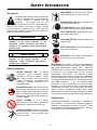
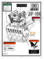
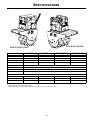
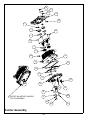
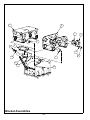
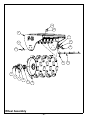
OPERATOR’S SAFETY
AND SERVICE MANUAL
UV-10K
This manual covers the following serial numbers
and higher for each model listed:
UV-10K 4040020
UVW-24 4042010
UVW-36 4041015
BOOM MOUNTED VIBRATORY ATTACHMENTS
MBW, Inc.
MBW (UK) Ltd.
250 Hartford Rd • PO Box 440
Slinger, WI 53086-0440
Phone: (262) 644-5234
Fax: (262) 644-5169
Email: [email protected]
Website: www.mbw.com
Units 2 & 3 Cochrane Street
Bolton BL3 6BN, England
Phone: 44 (0) 1204 387784
Fax: 44 (0) 01204 387797
Email: [email protected]
MBW France S.A.R.L.
Z.A. d’Outreville
5 rue Jean Baptiste Néron,
60540 BORNEL
France
Phone: +33 (0) 3 44 07 15 96
Fax +33 (0) 3 44 07 41 28
Email: [email protected]
L18898 / 06.11.d
©MBW, Inc. 2011
Printed in the USA
TABLE OF CONTENTS
Safety Information . . . . . . . . . . . . . . . . . . . . . . 1
Replacing Shockmounts. . . . . . . . . . . . . . . . . . . . . . . 5
Introduction . . . . . . . . . . . . . . . . . . . . . . . . . . . . . . . . . 1
Service. . . . . . . . . . . . . . . . . . . . . . . . . . . . . . . . 7
Safety Precautions . . . . . . . . . . . . . . . . . . . . . . . . . . . 1
Safety Decals . . . . . . . . . . . . . . . . . . . . . . . . . . . . . . . 1
Specifications. . . . . . . . . . . . . . . . . . . . . . . . . . 3
Operation . . . . . . . . . . . . . . . . . . . . . . . . . . . . . 4
Torque Chart . . . . . . . . . . . . . . . . . . . . . . . . . . . . . . . 7
Service Tools . . . . . . . . . . . . . . . . . . . . . . . . . . . . . . . 7
Vibration Head Disassembly . . . . . . . . . . . . . . . . . . . 7
Exciter Disassembly . . . . . . . . . . . . . . . . . . . . . . . . . . 7
Exciter Assembly . . . . . . . . . . . . . . . . . . . . . . . . . . . . 8
Introduction . . . . . . . . . . . . . . . . . . . . . . . . . . . . . . . . . 4
Vibration Head Assembly . . . . . . . . . . . . . . . . . . . . . . 8
Before Starting & Operating . . . . . . . . . . . . . . . . . . . . 4
Wheel Disassembly . . . . . . . . . . . . . . . . . . . . . . . . . . 8
Operating . . . . . . . . . . . . . . . . . . . . . . . . . . . . . . . . . . 4
Wheel Assembly. . . . . . . . . . . . . . . . . . . . . . . . . . . . . 9
Adjusting Pin-Type Mount. . . . . . . . . . . . . . . . . . . . . . 4
Parts Replacement Cycles and Tolerances . . . . . . . . 9
Disconnecting Wheel Assemblies. . . . . . . . . . . . . . . . 4
Connecting Wheel Assemblies . . . . . . . . . . . . . . . . . . 4
Maintenance . . . . . . . . . . . . . . . . . . . . . . . . . . . 5
Replacement Parts . . . . . . . . . . . . . . . . . . . . . 11
Exciter Assembly . . . . . . . . . . . . . . . . . . . . . . . . . . . 12
Bracket Assemblies . . . . . . . . . . . . . . . . . . . . . . . . . 14
Maintenance Schedule . . . . . . . . . . . . . . . . . . . . . . . . 5
Vibration Head Assembly . . . . . . . . . . . . . . . . . . . . . 16
Fluid Levels. . . . . . . . . . . . . . . . . . . . . . . . . . . . . . . . . 5
Wheel Assembly. . . . . . . . . . . . . . . . . . . . . . . . . . . . 18
Changing Exciter Oil . . . . . . . . . . . . . . . . . . . . . . . . . . 5
Checking Exciter Oil Level . . . . . . . . . . . . . . . . . . . . . 5
Warranty . . . . . . . . . . . . . . . . . . . . . . . . . . . . . 20
WARNING
CALIFORNIA PROPOSITION 65 WARNING
Engine exhaust and some of its constituents are
known in the state of California to cause cancer,
birth defects, and other reproductive harm.
SAFETY INFORMATION
Introduction
SAFE DRESS: Do not wear loose clothing,
rings, wristwatches, etc. near machinery.
This Safety Alert Symbol is used to call attention
to items or operations which may be dangerous
to those operating or working with this
equipment.
The symbol can be found
throughout this manual and on the unit. Please read these
warnings and cautions, along with all decals, carefully
before attempting to operate the unit. Make sure every
individual who operates or works with this equipment is
familiar with all safety precautions.
NOISE PROTECTION: Wear OSHA specified
hearing protection devices.
EYE PROTECTION: Wear OSHA specified
eye shields, safety glasses, and sweat bands.
FOOT PROTECTION: Wear OSHA specified
steel-tipped safety shoes.
WARNING
HEAD PROTECTION: Wear OSHA specified
safety helmets.
GENERAL WARNING.
Indicates information
important to the proper operation of the
equipment. Failure to observe may result in
damage to the equipment and/or severe bodily
injury or death.
DUST PROTECTION: Wear OSHA specified
dust mask or respirator.
CAUTION
OPERATOR: Keep children and bystanders
off and away from the equipment.
GENERAL CAUTION.
Indicates information
important to the proper operation of the
equipment. Failure to observe may result in
damage to the equipment.
REFERENCES: For details on safety rules and regulations
in the United States, contact your local Occupational Safety
and Health Administration (OSHA) office. Equipment
operated in other countries must be operated and serviced
in accordance and compliance with any and all safety
requirements of that country. The publication of these
safety precautions is done for your information. MBW does
not by the publication of these precautions, imply or in any
way represent that these are the sum of all dangers present
near MBW equipment.
If you are operating MBW
equipment, it is your responsibility to insure that such
operation is in full accordance with all applicable safety
requirements and codes. All requirements of the United
States Federal Occupational Safety and Health
Administration Act must be met when operated in areas that
are under the jurisdiction of that United States Department.
Safety Precautions
LETHAL EXHAUST GAS: An internal
combustion engine discharges carbon
monoxide, a poisonous, odorless, invisible
gas. Death or serious illness may result if
inhaled. Operate only in an area with proper
ventilation.
NEVER OPERATE IN A
CONFINED AREA!
DANGEROUS FUELS: Use extreme caution
when storing, handling and using fuels, as
they are highly volatile and explosive in vapor
state. Do not add fuel while engine is running.
Stop and cool the engine before adding fuel.
DO NOT SMOKE!
Safety Decals
SAFETY GUARDS: It is the owner's
responsibility to ensure that all guards and
shields are in place and in working order.
Carefully read and follow all safety decals. Keep them in
good condition. If decals become damaged, replace as
required. If repainting the unit, replace all decals. Decals
are available from authorized MBW distributors. Order the
decal set listed on the following page(s).
IGNITION SYSTEMS: Breakerless, magneto,
and battery ignition systems can cause severe
electrical shocks. Avoid contacting these
units or their wiring.
-1-
RETURN
PRESSURE
OPERATING INSTRUCTIONS
1. Back pressure in return lines MUST NOT
EXCEED 200 PSI.
2. Hydraulic Requirements:
Pressure 1500-3000 psi
Volume
20-70 gpm
3. Check for loose hardware after every 20
hours of operation.
4. Do not run exciter when attachment is not
in contact of backfill.
5. Not recommended for use on excavators
over 60,000 lbs.
18854
U.S. PATENT 5,244,306
U.S. PATENTS PENDING
13066
13066
15874
18854
18853
DANGER
Attachment may disconnect and
cause serious damage or injury
if bolts loosen during use.
Before each use, inspect locking
plates and ensure tightness of
fasteners.
19042
19042
18828-UVW36
18855-UVW24
WARNING
WARNING
18860
Machine may fall and cause
serious damage or injury if lifted
improperly.
Lift Machine using holes in upper
mounting bracket.
MACHINE WEIGHT
UVW-24 - 2500 lbs (1130 kg)
UVW-36 - 3000 lbs (1360 kg)
Do NOT use machine to lift other equipment.
18860
13019
Safety Decals
MOVING PARTS CAN
CRUSH AND CUT
STAY CLEAR OF
MOVING PARTS
13019
-2-
SPECIFICATIONS
W-36 & UV-10K (PIN)
W-24 & UV-10K (FLAT)
W-24
W-36
UV-10K (PIN)
UV-10K (FLAT)
Excavator Connection
Flat Top Style
Flat Top Style
Adjustable Pin Style
Flat Top Style
Static Weight*
1367 lbs (620 Kg)*
1750 lbs (794 Kg)*
1019 lbs (462 Kg)*
1095 lbs (497 Kg)*
Overall Width
24” (61 cm)
36” (91 cm)
24” (61 cm)
24” (61 cm)
Drum width
21” (53 cm)
33” (84 cm)
-
-
1500-3000 psi
1500-3000 psi
20-70 gpm
20-70 gpm
1” Male JIC 37º
1” Male JIC 37º
Drum diameter
28” (71 cm)
Exciter speed
3000 rpm
Centrifugal Force
10,000 lbs (45Kn)
Compaction Depth
24” (61 cm)
HYDRAULIC REQUIREMENTS
Pressure
Flow
Connection
Specifications subject to change without notice
* Static weight does not include weight of bonnets or auxiliary lines not manufactured by MBW
-3-
OPERATION
Introduction
Adjusting Pin-Type Mount
MBW equipment is intended for use in very severe
applications.
The UV-10K can be ordered with an adjustable mounting
system which can adjust to allow for excavator booms 9” to
15” wide. The center distance is fixed at 17.5”. Refer to Pin
Mount Assembly, page 14.
This parts manual contains only standard parts. Variations
of these parts as well as other special parts are not included.
Contact your local MBW distributor for assistance in
identifying parts not included in this manual.
1.
Loosen, but do not remove, the 16 retaining bolts.
2.
Tap bushings with a aluminum or rubber mallet to
move them in or out. Leave 1/4” of play between
bushings and boom.
3.
In regaurd to the mounting bracket, bushings must be
symetric. Also, the ends of the bushings can not be
inset of the clamping rings.
4.
Tighten bolts with pins in place to ensure correct
alignment of the bushings.
Before Starting & Operating
• REMEMBER! It is the owner’s responsibility to
communicate information on the safe use and proper
operation of this unit to the operators.
• Review ALL of the Safety Precautions listed on page 1 of
this manual.
Disconnecting Wheel Assemblies
• Familiarize yourself with the operation of the machine
and confirm that all controls function properly.
Refer to Vibration Head Assembly, page 16.
• Know how to STOP the machine in case of an
emergency.
1.
Support blade with blocks and chock the wheel so
that unit is secure, stable, and upright.
• Make sure hands, feet, and clothing are at a safe
distance from any moving parts.
2.
Remove locknuts (#21), washers (#22), and locking
collars (#17) .
• OIL LEVEL - Check the oil level in the engine. For more
information see “Lubrication” under the respective
engine’s “Owners Manual” or the Maintenance section of
this manual.
3.
Loosen and remove bolts (#14).
4.
Lift vibration head assembly straight up to remove it
from the wheel assembly.
Connecting Wheel Assemblies
Operating
Refer to Vibration Head Assembly, page 16.
1.
Do not run exciter when roller attachment is not in
contact with the ground.
1.
2.
The UV-10K attachments are not recommended for
excavators exceeding 60,000 lbs.
Carfully align vibration head assembly and wheel
frame so that mounting holes align, and set in place.
2.
3.
The operating pressure supplied to the control valve
must be between 1500 and 3000 psi.
Tighten the bolts (#14) to 480 ft-lbs in a cross-wise
pattern.
3.
4.
The flow supplied to the control block must be
between 20 and 70 gpm.
Install locking plates (#17) on all 6 bolts and secure
with washers and locknuts (#21)
5.
Do not apply excessive down force when compacting
soil.
WARNING
Always stop the engine before:
Leaving the equipment unattended for any
amount of time.
CAUTION
Back pressure in return line must not exceed 200
PSI. Excessive back pressure can damage hydraulic motor.
Before making any repairs or adjustments to the
machine.
-4-
MAINTENANCE
WARNING
CAUTION
Always exercise the stopping procedure before
servicing or lubricating the unit.
Always verify fluid levels and check for leaks after
changing fluids.
After servicing the unit, replace and fasten all
guards, shields, and covers to their original
positions before resuming operation.
Do not drain oil onto ground, into open streams,
or down sewage drains.
Maintenance Schedule
SYSTEM
MAINTENANCE
Drum hubs
Grease
Exciter
Check oil level
DAILY
EVERY 50
HOURS
EVERY 250
HOURS
YEARLY
X
X
X
X
Check for oil leaks
X
Change oil
Tighten Bolts1
X
X
Hardware
Check and tighten as needed1
X
X
Shockmounts
Check for cracks or tears
X
X
Isolation mats
Check for cracks, tears, or wear
X
1.
Check all hardware after the first 5 hours of use, then follow the maintenance schedule.
Fluid Levels
1.
SYSTEM
FLUID VOLUME
RECOMMENDED OIL
Exciter
17 oz
MBW Ground Pounder® Exciter Oil1
MBW #01058 ---- 6-Pack (8 oz bottles)
MBW #17320 ---- 1 quart (32 oz)
Changing Exciter Oil
Checking Exciter Oil Level
Refer to Exciter Assembly, page 12.
Refer to Vibration Head Assembly, page 16.
1.
Follow Disconnecting Wheel Assemblies, page 4.
1.
2.
Support the Vibration Head over a drain pan and
remove the drain plug (#19).
Hold Vibration Head Assembly level and remove the
sight gage cover (#10).
2.
Oil Level should be visible near the top of the gage.
3.
If necessary, remove fill plug on top of exciter and
add MBW Ground Pounder ® Exciter oil. Do not
overfill.
3.
Reinstall the drain plug using a thread sealing
compound.
4.
Clean the area around the fill plug (#24) and remove
it through access holes in mount weldment.
5.
Make sure vibration head is level, and fill exciter with
MBW Ground Pounder® Exciter oil until the level is
visible centered in the sight gage (#3). See chart for
proper amounts.
6.
Replacing Shockmounts
Refer to Bracket Assemblies, page 14.
1.
Reinstall fill plug using a thread sealing compound.
-5-
Remove unit from excavator and support blade with
blocks and chock the wheel so that unit is secure,
stable, and upright.
2.
Remove the 6 nuts (#13) and bolts (#12) which
secure the mounting bracket to the vibration head
assembly and seperate the two with a suitable lifting
device.
3.
Remove old primary shock mounts (#1) by pressing
them out. A small hydraulic bottle jack or porta power
works best.
4.
After removing old mount, lubricate the new shock
mount and inner cylindrical surface of UV frame prior
to assembly. Be sure to apply enough lubricant to
completely cover both surfaces.
7.
Remove secondary and third compression mounts (#
5) by removing the clamping strips (# 3) on each side.
It may be necasary to insert a screwdriver between
the compression mount and the weldment (# 4) to
start removing the rubber.
8.
Clamp new secondary and third mounts into place.
Mounts should be as tight as possible.
9.
Reinstall mounting bracket. To avoid noise during
operation, make sure the bottom of the third mounts
are rotated away from the mounting bracket as you
tighten the bolts as shown in figure 2.
Note: Lubricate with a soap or rubber lubricant. Do not
use grease or oil as it will deteriorate the rubber.
5.
Assemble components of tool, shock mount, and UV
frame as shown in Figure 1.
6.
Tighten nut until the shockmount is fully seated in the
frame.
GAP
FIGURE 2
5(&(667+,66,'(
FIGURE 1
5$',867+,66,'(
-6-
SERVICE
Service Tools
Assembly and disassembly should be performed by a
service technician who has been factory trained on MBW
equipment. The unit should be clean and free of debris.
Pressure washing before disassembly is recommended.
Part No.
• Prior to assembly, wash all parts in a suitable cleaner or
solvent.
• Check moving parts for wear and failure. Refer to the
Replacement section in this manual for tolerance and
replacement cycles.
Torsion mount install tool
16184
Torsion mount install lubricant
(included with 16163)
00709
Exciter Shim, .005”
Refer to Vibration Head Assembly, page 16.
• All gaskets and seals should be replaced after any
disassembly.
1.
Follow Disconnecting Wheel Assemblies, page 4
2.
Flip vibration head assembly over on a sturdy work
surface to expose the exciter and valve block.
3.
Loosen and remove the two main supply lines (#9 &
#12).
4.
Loosen and remove the two motor supply lines (#5 &
#6). Note orientation for proper reassembly later.
5.
Remove the four exciter nuts (#22), lock washers
(#20), and washers (#21).
6.
Note location of any shims for proper reassembly.
7.
Attach lifting chain to eyelets on exciter (#11), and lift
out.
8.
Remove valve block bolts (#19), and remove valve
block (#13).
Torque Chart
GRADE 2
GRADE 5
49 in•lbs
76 in•lbs
56 in•lbs
87 in•lbs
8 ft•lbs
13 ft•lbs
9 ft•lbs
14 ft•lbs
15 ft•lbs
23 ft•lbs
17 ft•lbs
26 ft•lbs
24 ft•lbs
37 ft•lbs
27 ft•lbs
41 ft•lbs
37 ft•lbs
57 ft•lbs
41 ft•lbs
64 ft•lbs
53 ft•lbs
82 ft•lbs
73 ft•lbs
112 ft•lbs
83 ft•lbs
112 ft•lbs
144 ft•lbs
200 ft•lbs
188 ft•lbs
483 ft•lbs
210 ft•lbs
541 ft•lbs
652 ft•lbs
1462 ft•lbs
3 ft•lbs
4 ft•lbs
6 ft•lbs
10 ft•lbs
10 ft•lbs
20 ft•lbs
CONVERSIONS
in•lbs x 0.083 = ft•lbs
ft•lbs x 12 = in•lbs
ft•lbs x 0.1383 = kg•m
ft•lbs x 1.3558 = N•m
16163
Vibration Head Disassembly
• All shafts and housings should be oiled prior to pressing
bearings. Also, ensure that the bearings are pressed
square and are seated properly.
SIZE
1/4-20
1/4-28
5/16-18
5/16-24
3/8-16
3/8-24
7/16-14
7/16-20
1/2-13
1/2-20
9/16-12
5/8-11
5/8-18
3/4-16
1-8
1-14
1-1/2-6
M6
M8
M 10
Description
GRADE 8
9 ft•lbs
10 ft•lbs
18 ft•lbs
20 ft•lbs
33 ft•lbs
37 ft•lbs
52 ft•lbs
58 ft•lbs
80 ft•lbs
90 ft•lbs
115 ft•lbs
159 ft•lbs
180 ft•lbs
315 ft•lbs
682 ft•lbs
764 ft•lbs
2371 ft•lbs
7 ft•lbs
18 ft•lbs
30 ft•lbs
Exciter Disassembly
Refer to Exciter Assembly, page 12.
1.
Drain exciter oil by removing both plugs (#19) and
slightly tipping exciter assembly towards the plugs.
2.
Remove both socket head cap screws (#21 & #22)
securing hydraulic motor (ref 18). Remove motor.
3.
Remove 14 bolts (#23) securing cover (#10) to
exciter housing and remove cover.
4.
Remove both snap rings (#4) and slide gears (#11 &
#12) off.
5.
Remove 8 bolts (#23) securing cover (#9) to exciter
housing, remove cover.
Note: If removing bearings from shaft assemblies or
housing, bearings MUST be replaced.
-7-
6.
Press both exciter shafts (#16 & #18) out of housing
(#8), use care not to damage shaft splines.
7.
Remove snap rings (#1) and press both bearings (#6)
from housing (#8).
8.
(A puller will be required to do this step) Remove
snap rings (#7) from both exciter shafts (#16 & #18)
and remove inner races.
9.
Remove both snap ring (#1) securing bearings (#5) in
cover (#9). Remove 4 bolts and washers (#17 &
#20).
9.
Install plugs (#19) and fill with 17oz of exciter oil,
install fill plug (#24).
Figure 3
SHIELDS
10. Support cover (#9) and use a brass punch to tap out
bearings (#5) alternate from side to side of each
bearing to eliminate binding of the bearing.
Exciter Assembly
Refer to Exciter Assembly, page 12.
1.
2.
3.
4.
5.
6.
Press inner race of bearing (#5) onto exciter shaft
(#16) and install snap ring (#7). Repeat procedure on
second exciter shaft.
Vibration Head Assembly
Press remaining portion of bearing (#5) into cover
(#9) and install snap ring (#1). Repeat procedure on
second bearing.
Refer to Vibration Head Assembly, page 16.
Press both bearings (#6) into housing (#8) and install
snap rings (#1).
Supporting inner race of bearing (#6) that is already
in housing (#8), press exciter shaft (#16) into the
bearing, repeat procedure on second exciter shaft. If
the inner race of the bearing (#6) is not supported
properly, the bearing can be damaged.
Apply GasketMaker type sealant onto gearbox
housing (#8). Make sure all 4 dowel pins (#14) are in
place and install cover (#9). Secure cover with bolts
(#23) and torque to 23 ft/lbs. Check and see that both
shafts rotate freely.
With the exciter housing sitting as shown, both
exciters shafts should be in a position with the heavy
side down. Install gears (#11 & #12) over the shafts
without rotating the shafts and install snap rings (#2).
See figure 3 for proper timing.
7.
Install gasket (#13) and cover (#10) onto housing
(#8). Ensure dowel pins (#4) are in place, secure
cover with bolts (#23), and torque to 23 ft/lbs.
8.
Apply GasketMaker type sealant and install motor
(#15). Secure with socket head cap screws and lock
washer (#21, #22, & #25).
1.
Loosely assemble fittings (#2) to motor on exciter as
shown.
2.
Place shims in proper locations, and set exciter in
place. If using a new exciter or new vibration head
weldment, use shims to ensure exciter sits flat in
weldment. No “rocking” should be noticeable.
3.
Bolt exciter into place with nuts (#22), lock washers
(#20), and washers (#21). Torque to 315 ft-lbs.
4.
Assemble fittings (#3 & #1) to valve block (#13) as
shown. Tighten fully.
5.
Install motor supply hose (#6) from the fitting on the
valve block closest to the exciter, to the fitting on the
motor closest to the side of the weldment (#15).
Route hose so that it will not chafe or become
pinched. Tighten hose and the motor fitting.
6.
Install second hose (#5) from the fitting on the valve
block farthest from the exciter, to the fitting on the
motor closest the center of the unit. Route the hose
so that it will not chafe or become pinched. Tighten
hose and the motor fitting.
7.
Install main supply lines (#9 & #12) so that they will
not chafe against the weldment (#15).
Wheel Disassembly
Refer to Wheel Assembly, page 18.
-8-
1.
Remove unit from excavator, support blade with
blocks and chock the wheel so that unit is secure,
stable, and upright.
2.
Wash the drum and lower frame to remove all dirt,
grime and sand that could contaminate the bearings.
3.
Secure an adequate lifting device to the mounting
bracket and lift the unit just enough to lift the wheel off
the ground.
Wheel Assembly
WARNING
Refer to Wheel Assembly, page 18.
See Specifications, page 3 for weight of your
machine. If unit is lifted improperly, it may fall and
cause serious injury or death.
1.
Remove the seal from one side of the bearing (#5).
2.
Insert bearing, seal-less side first, into the hub (#4).
4.
Loosen and remove the 12 bolts (#13) that secure the
wheel hubs to the frame.
3.
Assemble the bearing and hub subassembly onto the
axle.
5.
Carefully lift the machine off the wheel. To avoid
binding, be sure it lifts straight up. Move the machine
away so that work on the drum can be preformed
safely.
4.
Tighten the axle limiter cap (#6) on to the axle with
the three socket head cap screws (#9). Use a
medium strenth threadlocker, such as Loctite 242.
5.
Rotate the hubs so that the grease fittings (#1) are
straight down.
6.
Carefully lift the frame assembly onto the wheel and
align the bolt patterns on the frame and hubs.
7.
Insert and tighten the hex head cap screws (#16).
8.
Grease both zerks.
6.
Remove the socket head cap screws (#9) and Axle
limiter caps (#6).
7.
Pull the hubs (#4) off the axle.
8.
Clean the bore, and then remove the bearings (#5)
from the hubs.
Parts Replacement Cycles and Tolerances
Bearings
Replace anytime a bearing is rough, binding, discolored or removed from housing or
shaft.
Engine Components
Refer to your engine manufacturer’s Owner’s Manual.
Hardware
Replace any worn or damaged hardware as needed. Replacement hardware should
be grade 5 and zinc plated unless otherwise specified.
Safety Decals
Replace if they become damaged or illegible.
Seals & Gaskets
Replace if a leak is detected and at every overhaul or tear down.
Shock Mounts
Replace every 6 months.
Isolation mats
Replace every 6 months.
-9-
This page intentionally left blank.
- 10 -
REPLACEMENT PARTS
The warranty is stated in this book on page 18. Failure to
return the Warranty Registration Card renders the warranty
null and void.
MBW has established a network of reputable distributors/
dealers with trained mechanics and full facilities for
maintenance and rebuilding, and to carry an adequate parts
stock in all areas of the country. Their sales engineers are
available for professional consultation. If you cannot locate
an MBW distributor in your area, contact MBW or one of our
Sales Branches listed below.
STAMPED
When ordering replacement parts, be sure to have the
following information available:
• Model and Serial Number of machine when ordering
MBW parts
• Model and Serial Number of engine when ordering
engine parts
• Part Number, Description, and Quantity
• Company Name, Address, Zip Code, and Purchase
Order Number
DECAL
• Preferred method of shipping
REMEMBER - You own the best! If repairs are needed,
use only MBW parts purchased from authorized
MBW distributors.
The UV-10K’S serial number can be found in the following
locations:
• Decal- Rear of the vibration head
• Stamped- Edge of sideplate, rear of machine
The UVW-24 OR UVW-36’S serial number can be found in
the following locations:
• Decal- Rear support tube
Write Model Number here
• Stamped- Edge of support plate, opposite blade
Write Serial Number here
Contact Information
MBW, Inc.
MBW (UK) Ltd.
250 Hartford Rd • PO Box 440
Slinger, WI 53086-0440
Phone: (262) 644-5234
Fax: (262) 644-5169
Email: [email protected]
Website: www.mbw.com
Units 2 & 3 Cochrane Street
Bolton BL3 6BN, England
Phone: 01204 387784
Fax: 01204 387797
Email: [email protected]
- 11 -
MBW France S.A.R.L.
Z.A. d’Outreville
5 rue Jean Baptiste Néron,
60540 BORNEL
France
Phone: +33 (0) 3 44 07 15 96
Fax +33 (0) 3 44 07 41 28
Email: [email protected]
2))6(7210272572:$5'6
7232)$66(0%/<
Exciter Assembly
- 12 -
ITEM
1.
2.
3.
4.
5.
6.
7.
8.
9.
10.
11.
12.
13.
14.
15.
16.
17.
18.
19.
20.
21.
22.
23.
24.
25.
PART NO.
01000
19930
06457
07203
07456
07458
07469
09451
09453
09455
09457
09485
09741
09745
14267
18808
18841
19046
F0227SPP
F061604HCS
F061608SCS
F061610SCS
F061612FWS
F0618SPP
F06LW
01291
DESCRIPTION
RETAINING RING, INTERNAL 5000-315
RETAINING RING, EXTERNAL 1.375
GAGE, VIEW
PIN, DOWEL 1/4 X 1/2
BEARING, ROLLER 80 X 40
BEARING, SHPERICAL ROLLER
RETAINING RING, EXTERNAL 5108-156
HOUSING, MACHINED EXCITER
COVER, MACHINED REAR
COVER, MACHINED FRONT
GEAR, DRIVE LEFT
GEAR, DRIVE RIGHT
GASKET, COVER FRONT
PIN, DOWEL 3/8 X 1
MOTOR, HYD. CASAPPA HIGH PRES
EXCITER SHAFT, ASM
EYELET
EXCITER SHAFT, ASM, SPLINELESS
SOCKET PIPE PLUG, 1/8-27
HHCS, 3/8-16 X 1/2 Gr5 ZP
SCS, 3/8-16 X 1
SCS, 3/8 X 1-1/4
FWLS, 3/8-16 X 1-1/2 ZP
PLUG, PIPE 3/8-18(SEE DWG)
LOCKWASHER, 3/8 ZP
TIE, CABLE
26.
27.
28.
29.
30.
31.
32.
33.
34.
35.
36.
37.
38.
39.
40.
41.
42.
43.
44.
- 13 -
QTY
4
2
1
2
2
2
2
1
1
1
1
1
1
4
1
1
2
1
2
4
1
1
22
1
2
1
Bracket Assemblies
- 14 -
ITEM
1.
2.
3.
4.
5.
6.
7.
8.
9.
10.
11.
12.
13.
14.
PART NO.
12681
18805
18812
18815
18817
18829
18847
18870
F061610FWS
F121016HCS
F12LW
F240648HCS
F2406HN
F24LW
DESCRIPTION
MOUNT, TORSION
CLAMPING FLANGE
STRIP, CLAMPING
WELDMENT, MOUNTING, TERTIARY
MAT, TERTIARY
UPPER BRACKET, PIN MOUNT
RING, INTERNAL
UPPER BRACKET, FLAT TOP
FWLS, 3/8-16 X 1-1/4
HHCS, 3/4-10 X 2
LOCKWASHER, 3/4 ZP
HHCS, 1 1/2-6 X 6 GR8
HEX NUT, 1 1/2-6 GR8
LOCKWASHER, 1 1/2
- 15 -
FLAT
6
0
4
2
2
0
0
1
12
0
0
6
6
6
PIN
6
4
4
2
2
1
4
0
12
16
16
6
6
6
Vibration Head Assembly
- 16 -
ITEM
1.
2.
3.
4.
5.
6.
7.
8.
9.
10.
11.
12.
13.
14.
15.
16.
17.
18.
19.
20.
21.
22.
23.
24.
25.
PART NO.
08209
08730
14817
14819
18786
18787
18788
18789
18790
18800
18809
18845
18888
19149
20228
20238
20281
20282
F061608FWS
F061612FWS
F0616ELN
F06SW
F12LW
F12SW
F1216HN
18776
DESCRIPTION
FITTING, ST PARKER 10-12F50X
FITTING, ELBOW PARKER 8-10C50X
FITTING, ST PARKER 16-20 F50XS
FITTING, CAP PARKER 16-FN TX
HOSE, HYDRAULIC, 1/2 X 21
HOSE, HYDRAULIC, 1/2 X 15
CLAMPING BAR
MAT, ISOLATION
HOSE, 1 X 18 LONG ELBOW
COVER, SIGHT GAGE
EXCITER, UV10
HOSE, 1/2 X 18 SHORT ELBOW
VALVE, COMB. (HIGH FLOW EXA)
HHCS, 1-8 X 3-1/2 GR8
FRAME, EXCITER
HHCS, 3/4-16 X 12 GR8
LOCKING PLATE
STUD, 3/8-16 X 1-3/4 ZP
FWLS, 3/8-16 X 1 ZP
FWLS, 3/8-16 X 1-1/2 ZP
LOCKNUT, 3/8-16 NYLOC
WASHER, 25/64 X 1 X 1/8
LOCKWASHER, 3/4 ZP
WASHER, 13/16 X 2 X 9ga ZP
NUT, HEX 3/4-16 ZP
VIBRATION HEAD ASSEMBLY (Includes items 1-22)
- 17 -
QTY
2
2
2
2
1
1
2
1
1
1
1
1
1
4
1
4
6
6
2
12
6
6
4
4
4
Wheel Assembly
- 18 -
ITEM
1.
2.
3.
4.
5.
6.
7.
8.
9.
10.
11.
12.
13.
14.
15.
PART NO.
01177
18826
18837
18792
18861
19286
19290
19291
19292
19293
20234
20235
F081308SCS
F081316HCS
F08LW
F101116HCS
F101118HCS
F1011HN
F10LW
24W
36W
DESCRIPTION
FITTING, GREASE STD
SCRAPER TOOTH, WELDED, 1.5
SCRAPER TOOTH, WELDED, 2.0
SCRAPER BAR, 24
SCRAPER BAR, 36
HUB
BEARING, SPHERICAL PLAIN
AXLE LIMITER CAP
DRUM, UVW-24
DRUM, UVW-36
FRAME, ROLLER, 24
FRAME, ROLLER, 36
SCS, 1/2-13 X 1”
HHCS, 1/2-13 X 2
LOCKWASHER, 1/2
HHCS, 5/8-11 X 2
HHCS, 5/8-11 X 2-1/4 Gr8
NUT, HEX 5/8-11
LOCKWASHER, 5/8
ROLLER ASM, UVW-24 (INCLUDES ITEMS 1-8 AND 10-17
ROLLER ASM, UVW-36 (INCLUDES ITEMS 1-8 AND 10-17
- 19 -
24
2
8
0
1
0
2
2
2
1
0
1
0
4
16
16
3
12
3
15
36
2
0
12
0
1
2
2
2
0
1
0
1
4
24
24
5
12
5
17
WARRANTY
WHAT DOES THIS WARRANTY COVER? MBW, Incorporated (MBW)
warrants each New Machine against defects in material and workmanship
for a period of twelve (12) months. "New Machine" means a machine
shipped directly from MBW or authorized MBW dealer to the end user. This
warranty commences on the first day the machine is sold, assigned to a
rental fleet, or otherwise put to first use.
MBW warrants each Demonstration Machine against defects in material
and workmanship for a period of six (6) months. "Demonstration Machine"
means a machine used by MBW or its agents for promotional purposes.
This warranty commences on the first day the machine is sold, assigned to
a rental fleet, or otherwise put to first use.
This warranty covers the labor cost for replacement or repair of parts,
components, or equipment on New Machines or Demonstration Machines,
and MBW shall pay labor costs at MBW's prevailing rate to affect the
warranted repair or replacement. MBW reserves the right to adjust labor
claims on a claim-by-claim basis.
This warranty covers the shipping cost of replacement parts, components,
or equipment via common ground carriers from MBW to an authorized
MBW dealer. Air freight is considered only in cases where ground
transportation is not practical.
MAY THIS WARRANTY BE TRANSFERRED? This warranty is nontransferable and only applies to the original end user of a new machine or
demonstration machine.
WHAT DOES THIS WARRANTY NOT COVER?
1.This warranty does not cover any Used Equipment. "Used Equipment"
means any MBW machine or equipment that is not a New Machine or a
Demonstration Machine. All Used Equipment is sold AS IS/WHERE IS
WITH ALL FAULTS.
2.This warranty does not cover any New Machine, Demonstration
Machine, or their equipment, parts, or components altered or modified in
any way without MBW's prior written consent. This warranty does not
cover the use of parts not specifically approved by MBW for use on MBW
products. This warranty does not cover misuse, neglect, shipping damage,
accidents, acts of God, the operation of any New Machine or
Demonstration Machine in any way other than recommended by MBW in
accordance with its specifications, or any other circumstances beyond
MBW's control. This warranty does not cover any New Machine or
Demonstration Machine repaired by anyone other than MBW factory
branches or authorized MBW distributors.
3.This warranty does not cover, and MBW affirmatively disclaims, liability
for any damage or injury resulting directly or indirectly from design,
materials, or operation of a New Machine or Demonstration Machine or any
other MBW product. MBW's liability with respect to any breach of warranty
shall be limited to the provisions of this document and in no event shall
exceed an amount equal to the purchase price of the New Machine or
Demonstration Machine purchased from MBW.
4.This warranty does not cover engines, motors, and other assemblies or
components produced by other manufacturers and used on a New
Machine or Demonstration Machine, as said engines, motors, and other
assemblies or components may have warranties provided by the
manufacturer thereof. This warranty does not apply to consumable items,
such as v-belts, filters, trowel and screed blades, seals, shock mounts,
batteries, and the like, all of which are sold AS IS/WHERE IS WITH ALL
FAULTS.
5.This warranty does not cover the cost of transportation and other
expenses which may be connected with warranty service but not
specifically mentioned herein.
6.This warranty does not cover any updates to any New Machine,
Demonstration Machine, or any other MBW product. MBW reserves the
right to improve or make product changes without incurring any obligation
to update, refit, or install the same on New Machines or Demonstration
Machines previously sold.
WHAT MUST YOU DO TO OBTAIN WARRANTY COVERAGE? Each
New Machine or Demonstration Machine is accompanied by a Warranty
Registration Card. You must sign, date, and return the Warranty
Registration Card to the place of origin of the New Machine or
Demonstration Machine, either to MBW, Inc. at P.O. Box 440, Slinger,
Wisconsin 53086, MBW (UK), Ltd. at Units 2 & 3 Cochrane Street, Bolton
BL3 6BN, United Kingdom or MBW FRANCE SARL at
ZA D'Outreville, 5 Rue Jean Baptiste Neron, Bornel 60540 France, within
ten (10) days after purchase, assignment to a rental fleet, or first use. This
signed warranty card is the buyer's affirmation that he has read,
understood, and accepted the warranty at the time of purchase. Failure to
return the warranty card as specified herein renders the warranty null and
void. In order to receive warranty coverage consideration, warranty claims
must be submitted within thirty (30) days after the New Machine or
Demonstration Machine fails. Warranty claims must be submitted to MBW,
Inc., MBW (UK), Ltd. or MBW FRANCE SARL, and written authorization for
the return of merchandise or parts under the warranty must be obtained
before shipment to MBW.
WHAT WILL MBW DO? MBW's obligation under this warranty is limited to
the replacement or repair of parts for a New Machine or Demonstration
Machine at MBW factory branches or at authorized MBW distributors, and
such replacement or repair is the exclusive remedy provided hereunder.
Labor must be performed at an authorized MBW distributor. MBW
reserves the right to inspect and render a final decision on each warranty
case, and MBW's repair or replacement is solely within the discretion of
MBW.
IT IS EXPRESSLY AGREED THAT THIS SHALL BE THE SOLE AND
EXCLUSIVE REMEDY UNDER THIS WARRANTY. UNDER NO
CIRCUMSTANCES SHALL MBW BE LIABLE FOR ANY COSTS, LOSS,
EXPENSE, DAMAGES, SPECIAL DAMAGES, INCIDENTAL DAMAGES,
OR PUNITIVE DAMAGES ARISING DIRECTLY OR INDIRECTLY FROM
THE USE OF THE NEW MACHINE OR DEMONSTRATION MACHINE
WHETHER BASED UPON WARRANTY, CONTRACT, NEGLIGENCE,
STRICT LIABILITY, OR ANY OTHER LEGAL THEORY.
THE FOREGOING WARRANTY IS EXPRESSLY IN LIEU OF ALL
OTHER WARRANTIES, EXPRESS OR IMPLIED, INCLUDING THE
WARRANTIES OF MERCHANTABILITY, FITNESS FOR USE, AND
FITNESS FOR A PARTICULAR PURPOSE, AND ALL OTHER
OBLIGATIONS OR LIABILITY ON MBW'S PART. MBW NEITHER
ASSUMES NOR AUTHORIZES ANY OTHER PERSON TO ASSUME ON
BEHALF OF MBW ANY OTHER LIABILITY OR WARRANTY IN
CONNECTION WITH THE SALE OR SERVICE OF ANY NEW MACHINE,
DEMONSTRATION MACHINE , OR ANY OTHER MBW PRODUCT.
EXTENDED RAMMER WARRANTY - MODELS R422, R442,
R482 & R483.
This extended warranty commences on the last day of MBW’s standard,
one year, “limited warranty” and runs for an additional four years
(48 months). This extended warranty is limited to part replacement and
shipping costs of rammer bellows and non-metallic slide bearings only.
This extended warranty does not cover labor, down time, or any other cost
beyond that of component replacement and freight. This extended
warranty is subject to all limitations set fourth in MBW’s “limited warranty”,
above.
- 20 -
NOTES
- 21 -
NOTES
- 22 -