1
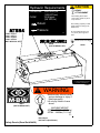
OPERATOR’S SAFETY
AND SERVICE MANUAL
AT73
AT84
This manual covers the following serial numbers
and higher for each model listed:
ATS73 . . . . . . . . . . . . . . . . . . . . 4070001
ATP73 . . . . . . . . . . . . . . . . . . . . 4070001
ATS84 . . . . . . . . . . . . . . . . . . . . 4080001
ATP84 . . . . . . . . . . . . . . . . . . . . 4080001
SKID-STEER ROLLER ATTACHMENTS
MBW, Inc.
MBW (UK) Ltd.
MBW France S.A.R.L
250 Hartford Rd • PO Box 440
Slinger, WI 53086-0440
Phone: (262) 644-5234
Fax: (262) 644-5169
Email: [email protected]
Website: www.mbw.com
Units 2 & 3 Cochrane Street
Bolton BL3 6BN, England
Phone: 44 (0) 01204 387784
Fax:44 (0) 01204 387797
Z.A. d’Outreville
5 rue Jean Baptiste Néron,
60540 BORNEL
France
Phone: +33 (0) 3 44 07 15 96
Fax: +33 (0) 3 44 07 41 28
L17993 / 05.11.E
©MBW, Inc. 2007
Printed in the USA
TABLE OF CONTENTS
Safety Information . . . . . . . . . . . . . . . . . . . . . . 1
Service. . . . . . . . . . . . . . . . . . . . . . . . . . . . . . . . 7
Introduction . . . . . . . . . . . . . . . . . . . . . . . . . . . . . . . . . 1
Torque Chart . . . . . . . . . . . . . . . . . . . . . . . . . . . . . . . 7
Safety Precautions . . . . . . . . . . . . . . . . . . . . . . . . . . . 1
Service Tools . . . . . . . . . . . . . . . . . . . . . . . . . . . . . . . 7
Safety Decals . . . . . . . . . . . . . . . . . . . . . . . . . . . . . . . 1
Replacing Shockmounts. . . . . . . . . . . . . . . . . . . . . . . 7
Specifications. . . . . . . . . . . . . . . . . . . . . . . . . . 3
Operation . . . . . . . . . . . . . . . . . . . . . . . . . . . . . 4
Introduction . . . . . . . . . . . . . . . . . . . . . . . . . . . . . . . . . 4
Before Starting & Operating . . . . . . . . . . . . . . . . . . . . 4
Connecting to Loader . . . . . . . . . . . . . . . . . . . . . . . . . 4
Replacing Input Seal . . . . . . . . . . . . . . . . . . . . . . . . . 7
Removing Drive Coupler . . . . . . . . . . . . . . . . . . . . . . 7
Installing Drive Coupler . . . . . . . . . . . . . . . . . . . . . . . 8
Removing Exciter Bearings and Shaft.. . . . . . . . . . . . 8
Installing Exciter Bearings and Shaft.. . . . . . . . . . . . . 8
Parts Replacement Cycles and Tolerances . . . . . . . . 9
Operating . . . . . . . . . . . . . . . . . . . . . . . . . . . . . . . . . . 4
Replacement Parts . . . . . . . . . . . . . . . . . . . . . 11
Maintenance . . . . . . . . . . . . . . . . . . . . . . . . . . . 5
Drum Assembly . . . . . . . . . . . . . . . . . . . . . . . . . . . . 12
Maintenance Schedule . . . . . . . . . . . . . . . . . . . . . . . . 5
Fluid Levels. . . . . . . . . . . . . . . . . . . . . . . . . . . . . . . . . 5
Changing Exciter Oil . . . . . . . . . . . . . . . . . . . . . . . . . . 5
Checking Exciter Oil . . . . . . . . . . . . . . . . . . . . . . . . . . 6
Main Assembly . . . . . . . . . . . . . . . . . . . . . . . . . . . . . 14
Spider Assembly . . . . . . . . . . . . . . . . . . . . . . . . . . . 16
Warranty . . . . . . . . . . . . . . . . . . . . . . . . . . . . . 18
WARNING
CALIFORNIA PROPOSITION 65 WARNING
Engine exhaust and some of its constituents are
known in the state of California to cause cancer,
birth defects, and other reproductive harm.
SAFETY INFORMATION
Introduction
SAFE DRESS: Do not wear loose clothing,
rings, wristwatches, etc. near machinery.
This Safety Alert Symbol is used to call attention
to items or operations which may be dangerous
to those operating or working with this
equipment.
The symbol can be found
throughout this manual and on the unit. Please read these
warnings and cautions, along with all decals, carefully
before attempting to operate the unit. Make sure every
individual who operates or works with this equipment is
familiar with all safety precautions.
NOISE PROTECTION: Wear OSHA specified
hearing protection devices.
EYE PROTECTION: Wear OSHA specified
eye shields, safety glasses, and sweat bands.
FOOT PROTECTION: Wear OSHA specified
steel-tipped safety shoes.
WARNING
HEAD PROTECTION: Wear OSHA specified
safety helmets.
GENERAL WARNING.
Indicates information
important to the proper operation of the
equipment. Failure to observe may result in
damage to the equipment and/or severe bodily
injury or death.
DUST PROTECTION: Wear OSHA specified
dust mask or respirator.
CAUTION
OPERATOR: Keep children and bystanders
off and away from the equipment.
GENERAL CAUTION.
Indicates information
important to the proper operation of the
equipment. Failure to observe may result in
damage to the equipment.
REFERENCES: For details on safety rules and regulations
in the United States, contact your local Occupational Safety
and Health Administration (OSHA) office. Equipment
operated in other countries must be operated and serviced
in accordance and compliance with any and all safety
requirements of that country. The publication of these
safety precautions is done for your information. MBW does
not by the publication of these precautions, imply or in any
way represent that these are the sum of all dangers present
near MBW equipment.
If you are operating MBW
equipment, it is your responsibility to insure that such
operation is in full accordance with all applicable safety
requirements and codes. All requirements of the United
States Federal Occupational Safety and Health
Administration Act must be met when operated in areas that
are under the jurisdiction of that United States Department.
Safety Precautions
LETHAL EXHAUST GAS: An internal
combustion engine discharges carbon
monoxide, a poisonous, odorless, invisible
gas. Death or serious illness may result if
inhaled. Operate only in an area with proper
ventilation.
NEVER OPERATE IN A
CONFINED AREA!
DANGEROUS FUELS: Use extreme caution
when storing, handling and using fuels, as
they are highly volatile and explosive in vapor
state. Do not add fuel while engine is running.
Stop and cool the engine before adding fuel.
DO NOT SMOKE!
Safety Decals
SAFETY GUARDS: It is the owner's
responsibility to ensure that all guards and
shields are in place and in working order.
Carefully read and follow all safety decals. Keep them in
good condition. If decals become damaged, replace as
required. If repainting the unit, replace all decals. Decals
are available from authorized MBW distributors. Order the
decal set listed on the following page(s).
IGNITION SYSTEMS: Breakerless, magneto,
and battery ignition systems can cause severe
electrical shocks. Avoid contacting these
units or their wiring.
-1-
CAUTION
Hydraulic Requirements
HEAVY
ATTACHMENT
PRESSURE: 1500-3000 psi
(103-207 bar)
FLOW:
10-50 gpm
(38-190 l/m)
Overloading skid loader
could cause loader to pitch
or tip forward.
Return
Check lifting capacity of skid
loader before hooking onto
attachment.
Pressure
17906 - ATS73
17907 - ATP73
17908 - ATS84
17909 - ATP84
(NOT IN DECAL SET)
14435
14435
Do not lift attachment over
12” (30cm) above ground
level.
READ OPERATORS MANUAL
BEFORE USING ATTACHMENT
14434
02355
02355
(NOT IN DECAL SET)
14434
!"#$%&%'
!"$*$#+$*,$.
#$"#$*$6
11922
WARNING
09867
09867
(NOT IN DECAL SET)
Machine may fall and cause
serious damage or injury if
lifted improperly.
Lift only by holes in frame
above.
MACHINE WEIGHT
ATS84- 2300 lbs (1043 kg)
ATP84- 2450lbs (1111 kg)
18075
18075-AT84
18074-AT74 (Not Shown)
Safety Decals (Decal Set #14436)
-2-
SPECIFICATIONS
ATP84
ATS73
ATP73
ATS84
ATP84
Centrifugal Force
8850 lbs (4014 kg)
9765 lbs (4429 kg)
Exciter Speed
3000 rpm
3000 rpm
Dynamic Linear Force
121 lb/in (21.7 kg/cm)
116 lb/in (20.8 kg/cm)
Amplitude
-
-
Length
43.3 in (110 cm)
43.3 in (110 cm)
Height
29 in (74 cm)
30 in (76 cm)
29 in (74 cm)
30 in (76 cm)
Weight
2070 lbs (939kg)
2210 lbs (1002 kg)
2300 lbs (1043 kg)
2450 lbs (1111 kg)
Width, Working
73 in (185 cm)
84 in (213 cm)
Width, Overall
78 in (198 cm)
89 in (226 cm)
Sound Pressure Level
85 dBa
85 dBa
Pressure Requirement
1500 - 3000 psi (10.3 - 20.7 MPa)
1500 - 3000 psi (10.3 - 20.7 MPa)
Flow Rate Requirement
10 - 50 GPM (38 - 176 LPM)
10 - 50 GPM (38 - 176 LPM)
Connection
1/2” Flat-face Quick Coupling
1/2” Flat-face Quick Coupling
Specifications subject to change without notice
-3-
OPERATION
Introduction
4.
MBW equipment is intended for use in very severe
applications.
Lower the roller, and engage the loaders’ arms into
their float mode.
5.
Engage the auxiliary hydraulics and allow the vibrator
to come up to speed.
This parts manual contains only standard parts. Variations
of these parts as well as other special parts are not included.
Contact your local MBW distributor for assistance in
identifying parts not included in this manual.
Operating
• Check for loose hardware every 20 hours of operation.
• Do not run exciter when roller is not in contact with the
ground.
Before Starting & Operating
• REMEMBER! It is the owner’s responsibility to
communicate information on the safe use and proper
operation of this unit to the operators.
• Check that rated capacity of skid steer loader meets or
exceeds weight of roller attachment.
• The operating pressure supplied to the control valve
must fall in the range of 1500 to 3000 psi.
• Review ALL of the Safety Precautions listed on page 1 of
this manual.
• The minimum volume requirement supplied to the control
valve is 10 gpm, but do not exceed 50 gpm.
• Familiarize yourself with the operation of the machine
and confirm that all controls function properly.
• Do not use excessive down pressure when compacting
soil.
• Know how to STOP the machine in case of an
emergency.
• Make sure hands, feet, and clothing are at a safe
distance from any moving parts.
WARNING
Always stop the engine before:
Connecting to Loader
1.
Attach the roller to the skid steer loader with the
universal bracket. Be sure that the wedges and
levers are fully engaged and locked.
2.
Connect the hydraulic hoses to the skid steer loader’s
auxiliary hydraulics supply using the quick couplers.
3.
If skid loader is equipped with a high flow and low flow
ports, it is recommended to use the low flow side.
Adding fuel.
Leaving the equipment unattended for any
amount of time.
Before making any repairs or adjustments to the
machine.
-4-
MAINTENANCE
WARNING
CAUTION
Always exercise the stopping procedure before
servicing or lubricating the unit.
Always verify fluid levels and check for leaks after
changing fluids.
After servicing the unit, replace and fasten all
guards, shields, and covers to their original
positions before resuming operation.
Do not drain oil onto ground, into open streams,
or down sewage drains.
Maintenance Schedule
SYSTEM
Exciter
MAINTENANCE
EACH USE
Check oil level
EVERY 50
HOURS
X
X
X
Change oil
Tighten Bolts1
X
X
Check and tighten as needed1
X
X
X
X
Shock mounts Check for cracks or tears
1.
YEARLY
X
Check for oil leaks
Hardware
EVERY 250
HOURS
Check all hardware after the first 5 hours of use, then follow the maintenance schedule.
Fluid Levels
1.
SYSTEM
FLUID VOLUME
RECOMMENDED OIL
AT73 Exciter
80 oz.
MBW Ground Pounder® Exciter Oil1
AT84 Exciter
128 oz.
MBW Ground Pounder® Exciter Oil1
MBW #01058 ---- 6-Pack (8 oz. bottles)
MBW #17320 ---- 1 quart (32 oz.)
Changing Exciter Oil
1.
Rotate drum until the fill/drain plug is at bottom of
drum. The fill/drain plug is the larger, square head
plug on the vent side of the roller.
2.
Place drain pan under plug and remove both plugs.
3.
Raise driven side of drum several inches so all oil can
drain out.
4.
After all oil has drained, return drum to a level
surface.
5.
Rotate drum until fill/drain plug is at the top of the
drum.
6.
Remove oil check plug from bottom of cover. The oil
check valve is smaller than the fill plug, and it has an
allen head drive as opposed to the square head
found on the fill/drain plug.
Oil Fill/Drain
Access Plug
DO NOT REMOVE
Oil check plug
-5-
7.
Fill exciter with MBW Ground Pounder® Exciter Oil
until oil starts to drain from oil check plug. See chart
for proper amounts.
2.
Remove oil check plug. The plug is the smaller of the
two on the vent side which also has an allen head
drive.
8.
Replace both plugs.
3.
Rotate drum until check plug is at 6 o’clock position.
4.
If oil level is adequate, it should dribble out of hole.
5.
If necasary, remove fill/drain plug, and add MBW
Ground Pounder® Exciter Oil.
Checking Exciter Oil
1.
Place drum on a level surface
-6-
SERVICE
Service Tools
Assembly and disassembly should be performed by a
service technician who has been factory trained on MBW
equipment. The unit should be clean and free of debris.
Pressure washing before disassembly is recommended.
• Prior to assembly, wash all parts in a suitable cleaner or
solvent.
• All shafts and housings should be oiled prior to pressing
bearings. Also, ensure that the bearings are pressed
square and are seated properly.
• All bearings should be replaced when rebuilding any
exciter or gearbox.
• All gaskets and seals should be replaced after any
disassembly.
Torque Chart
GRADE 2
GRADE 5
49 in•lbs
76 in•lbs
56 in•lbs
87 in•lbs
8 ft•lbs
13 ft•lbs
9 ft•lbs
14 ft•lbs
15 ft•lbs
23 ft•lbs
17 ft•lbs
26 ft•lbs
24 ft•lbs
37 ft•lbs
27 ft•lbs
41 ft•lbs
37 ft•lbs
57 ft•lbs
41 ft•lbs
64 ft•lbs
53 ft•lbs
82 ft•lbs
73 ft•lbs
112 ft•lbs
83 ft•lbs
112 ft•lbs
144 ft•lbs
200 ft•lbs
188 ft•lbs
483 ft•lbs
210 ft•lbs
541 ft•lbs
652 ft•lbs
1462 ft•lbs
3 ft•lbs
4 ft•lbs
6 ft•lbs
10 ft•lbs
10 ft•lbs
20 ft•lbs
CONVERSIONS
in•lbs x 0.083 = ft•lbs
ft•lbs x 12 = in•lbs
ft•lbs x 0.1383 = kg•m
ft•lbs x 1.3558 = N•m
Description
07353
CLUTCH REMOVAL TOOL
Replacing Shockmounts
• Check moving parts for wear and failure. Refer to the
Replacement section in this manual for tolerance and
replacement cycles.
SIZE
1/4-20
1/4-28
5/16-18
5/16-24
3/8-16
3/8-24
7/16-14
7/16-20
1/2-13
1/2-20
9/16-12
5/8-11
5/8-18
3/4-16
1-8
1-14
1-1/2-6
M6
M8
M 10
Part #
GRADE 8
9 ft•lbs
10 ft•lbs
18 ft•lbs
20 ft•lbs
33 ft•lbs
37 ft•lbs
52 ft•lbs
58 ft•lbs
80 ft•lbs
90 ft•lbs
115 ft•lbs
159 ft•lbs
180 ft•lbs
315 ft•lbs
682 ft•lbs
764 ft•lbs
2371 ft•lbs
7 ft•lbs
18 ft•lbs
30 ft•lbs
1.
Support roller to prevent it from rolling, and remove
hydraulic hoses from motor.
2.
Remove the two bolts securing the hydraulic motor
and remove the motor.
3.
Remove all external shockmount hardware while
supporting frame. Lift frame assembly off of drum
assembly.
4.
Pull spider off of drum.
5.
Replace shockmounts as needed.
6.
While spider is removed, inspect coupling and seal
for excessive wear. Replace if needed.
7.
Reinstall spider onto drum and then into the frame
8.
Install motor, align with coupler and secure with
mounting screw and lock washer. Use a medium
strength thread locker. Make sure motor mount
surface bottoms out in frame.
9.
Connect hoses.
Replacing Input Seal
Refer to Main Assembly, page 14.
1.
Remove drum assembly from frame and spider from
drum (See “replacing shockmounts” steps 1-4)
2.
Using a seal puller, remove seal. Note it is not
necessary to remove gear coupler (#15)
3.
Inspect the sealing surface on the shaft for wear or
damage.
4.
If the shaft has any sign of wear or damage, remove
the gear coupler (#15) and use the sleeve included
with seal. (Follow instructions included with seal kit).
If the shaft is in good condition install only the seal.
Use a seal protector when installing the seal.
Removing Drive Coupler
Refer to Main Assembly, page 14.
-7-
1.
Remove hydraulic lines from motor.
2.
Remove hydraulic motor (# 6).
3.
Remove drive coupler (# 13) gear from motor by
loosening clamping screw.
4.
Installing Exciter Bearings and Shaft.
To remove coupler gear (# 15) from exciter shaft will
require 07353 clutch removal tool. Turn coupler gear
clockwise (left hand threads) to remove.
Refer to Drum Assembly, page 12.
Installing Drive Coupler
1.
Install new bearings (# 8) into housings (# 5 & 14).
Use oil on the OD of the bearing and press on the
outer race of the bearing. Failure to do so will result
in damage to the bearings.
Refer to Main Assembly, page 14.
1.
Install new coupler gear (# 15) into shaft. Make sure
coupler bottoms out. Use high strength threadlocker.
2.
2.
Slide new coupler gear on to motor splines and
tighten clamping screw. Use a medium strength
thread locker on the screw.
Install new O-rings (# 7) onto housing (# 5 & 14),
lightly grease O-ring and housing surface which
slides into the drum.
3.
Install exciter shaft (# 13) into drum. Leave seal side
of exciter assembly stick out of the drum about 12".
4.
Take the seal side housing assembly (# 14), lightly oil
the exciter shaft bearing journal and apply Loctite 515
gasket eliminator, or equilivant, to mating flange.
Slide housing assembly onto shaft and install snap
ring (# 9) through seal bore onto shaft. Do not install
seal at this time.
5.
Slide exciter shaft and housing assembly into drum.
Use care to press housing in evenly. Secure with six
bolts (# 19). Use medium strength thread locker.
Install two bolts (# 18) in the push out holes to protect
the threads.
6.
To aid in assembly, insert a piece of ¾" round stock in
the vent end of the exciter shaft. Take vent side
housing assembly (# 5), apply a light coat of oil to the
exciter shaft bearing journal, and Loctite 515 gasket
eliminator, or equilivant, to the mating flange. Slide
housing assembly over the ¾" round stock, exciter
shaft, and onto drum assembly. Have someone lift up
the exciter shaft while aligning the housing assembly
with mounting holes in the drum and slide the
assembly on evenly.
7.
Install the six bolts (# 19) use medium strength thread
locker. Install two bolts (# 18) in the push out holes to
protect threads. Make sure exciter assembly rotates
freely.
8.
Remove ¾" round stock and install vent cover (# 11).
Make sure felt filter (# 1), retainer (# 2) and spiral pin
(# 15) are in place.
9.
Press seal into housing (# 14) using care to keep seal
square with bore.
3.
Install motor (# 6), align with coupler and secure with
mounting screw (# 23) and lock washer (# 24). Use
a medium strength thread locker. Make sure motor
mount surface bottoms out in frame.
4.
Connect hoses.
Removing Exciter Bearings and Shaft.
Whenever a complete disassembly is done all bearings,
gaskets, O-rings and seals should be replaced.
Refer to Drum Assembly, page 12.
1.
Drain exciter oil (Refer to Changing Exciter Oil, page
5.)
2.
Remove drum assembly from frame and spider from
drum (Refer to Replacing Shockmounts, page 7.
Steps 1-4).
3.
Remove input seal (# 10) from housing (# 14) using a
seal puller.
4.
Remove snap ring (# 9) from exciter shaft through
seal bore.
5.
Remove six bolts (# 19), securing housing (#14), to
the drum.
6.
Remove two push off bolts (# 19)
7.
Thread two 3/8-16x1 ½ bolts into these push off holes
evenly and push cover (# 14) off of drum. (If bolts are
not threaded in evenly the cover will bind) Remove
cover.
8.
Slide exciter shaft (#13) out of drum.
9.
Repeat steps 5-7 to remove cover (# 5) from the other
side.
10. Fill exciter housing with exciter oil. Refer to Changing
Exciter Oil, page 5. or proper procedure and amount.
10. Remove breather cover (# 11) by removing four
screws (# 17).
11. Install drive gear coupler (# 16, page 14) if removed.
12. Install spiders and frame.
11. Remove bearings (# 8) from covers (# 5 & 14).
(Bearings must be replaced if removed from covers)
-8-
Parts Replacement Cycles and Tolerances
Bearings
Replace anytime a bearing is rough, binding, discolored or removed from housing or
shaft.
Hardware
Replace any worn or damaged hardware as needed. Replacement hardware should
be grade 5 and zinc plated unless otherwise specified.
Safety Decals
Replace if they become damaged or illegible.
Seals & Gaskets
Replace if a leak is detected and at every overhaul or tear down.
-9-
This page intentionally left blank.
- 10 -
REPLACEMENT PARTS
The warranty is stated in this book on page 18. Failure to
return the Warranty Registration Card renders the warranty
null and void.
DECAL
MBW has established a network of reputable distributors/
dealers with trained mechanics and full facilities for
maintenance and rebuilding, and to carry an adequate parts
stock in all areas of the country. Their sales engineers are
available for professional consultation. If you cannot locate
an MBW distributor in your area, contact MBW or one of our
Sales Branches listed below.
When ordering replacement parts, be sure to have the
following information available:
STAMP
• Model and Serial Number of machine when ordering
MBW parts
• Model and Serial Number of engine when ordering
engine parts
• Part Number, Description, and Quantity
• Company Name, Address, Zip Code, and Purchase
Order Number
• Preferred method of shipping
REMEMBER - You own the best! If repairs are needed,
use only MBW parts purchased from authorized
MBW distributors.
The unit’s serial number can be found in the following
locations:
• The model and serial number are on the top front of the
roller frame
• The serial number is also stamped on the frame side
Write Model Number here
Write Serial Number here
Contact Information
MBW, Inc.
MBW (UK) Ltd.
MBW France S.A.R.L
250 Hartford Rd • PO Box 440
Slinger, WI 53086-0440
Phone: (262) 644-5234
Fax: (262) 644-5169
Email: [email protected]
Website: www.mbw.com
Units 2 & 3 Cochrane Street
Bolton BL3 6BN, England
Phone: 01204 387784
Fax: 01204 387797
Z.A. d’Outreville
11 rue Jean Baptiste Néron,
60540 BORNEL
France
Phone: +33 (0) 3 44 07 15 96
Fax: +33 (0) 3 44 07 41 28
- 11 -
9
10
14
8
18
3
19
13
4
8
20
7
16
6
12
3
19
18
5
7
11
1
2
15
17
Drum Assembly
- 12 -
7.
8.
9.
10.
11.
12.
13.
14.
15.
16.
17.
18.
19.
20.
ATS84
01072
01191
07011
08188
17807
17911
17811
17913
17813
17844
17845
17846
18111
17853
17854
17858
17859
17938
F0205SP
F0418SPP
F042005FSS
F061604HCS
F061610FWS
F0618SHPP
ATP84
1.
2.
3.
4.
5.
6.
DESCRIPTION
ATS73
PART NO.
ATP73
ITEM
FILTER, FELT
RETAINING RING, INTERNAL, STAR
RETAINING RING, INTERNAL
DECAL, EXCITER OIL
COVER, EXCITER, BREATHER SIDE
DRUM, ATP73 (PADDED)
DRUM, ATS73 (SMOOTH)
DRUM, ATP84 (PADDED)
DRUM, ATS84 (SMOOTH)
O-RING, 7.234 ID X 0.139 DIA
BEARING, SPHERICAL ROLLER
RETAINING RING, EXTERNAL
KIT, SEAL, AT73-84
COVER, BREATHER
GASKET, COVER
SHAFT, AT73
SHAFT, AT84
COVER, EXCITER, SEAL SIDE
PIN, SPIROL 1/8” X 5/8”
SOCKET PIPE PLUG, 1/4”-18
FLAT HEAD SOCKET SCREW, 1/4”-20 X 5/8”
HEX HEAD CAP SCREW, 3/8”-16 X 1/2”
FLANGE HEAD CAP SCREW, 3/8”-16 X 1-1/4”
SQUARE HEAD PIPE PLUG, 3/8”-18
1
1
2
2
1
1
0
0
0
2
2
1
1
1
1
1
0
1
1
2
4
4
12
1
1
1
2
2
1
0
1
0
0
2
2
1
1
1
1
1
0
1
1
2
4
4
12
1
1
1
2
2
1
0
0
1
0
2
2
1
1
1
1
0
1
1
1
2
4
4
12
1
1
1
2
2
1
0
0
0
1
2
2
1
1
1
1
0
1
1
1
2
4
4
12
1
- 13 -
Main Assembly
- 14 -
4.
5.
6.
7.
8.
9.
10.
11.
12.
13.
14.
15.
16.
17.
18.
19.
20.
21.
22.
23.
24.
25.
26.
27.
28.
29.
30.
13166
17980
13984
14267
14747
17842
17843
17850
17851
17856
17924
17894
17925
17895
17975
17976
17977
17981
17979
18107
18127
18656
18657
F051836HCS
F0518FN
F05SW
F061607FWS
F061610SCS
F06LW
F081312HCS
F08LW
F101112HCS
F1011HN
F10LW
17994
ATS84
08213
08730
ATP84
1.
2.
3.
DESCRIPTION
ATS73
PART NO.
ATP73
ITEM
FITTING, STRAIGHT
FITTING, ELBOW
HOSE, HYDRAULIC 1/2” X 47.00”
HOSE, HYDRAULIC 1/2” X 55.00”
SHEET, SAFETY WALK 24”
MOTOR, HYDRAULIC
FITTING, STRAIGHT
FLAT FACE COUPLING, MALE 1/2”
FLAT FACE COUPLING, FEMALE 1/2”
FRAME, AT73
FRAME, AT84
GAURD, HOSE
SCRAPER BAR ATP73 (PADDED)
SCRAPER BAR ATS73 (SMOOTH)
SCRAPER BAR ATP84 (PADDED)
SCRAPER BAR ATS84 (SMOOTH)
COUPLER, GEAR, 9T SPLINE
SLEEVE, COUPLER, GEAR
COUPLER, GEAR, 1”-12 THREAD
HOSE, HYDRAULIC 1/2” X 53.5”
HOSE, HYDRAULIC 1/2” X 59.00”
VALVE COMBINATION (.203 ORIFICE)
HOSE, HYDRAULIC 3/4” X 64.00”
BRACKET, LEFT
BRACKET, RIGHT
HEX HEAD CAP SCREW, 5/16”-18 X 4-1/2”
NUT, FLANGE 5/16”-18
WASHER, 5/16” X 3/4” X 15GA
FLANGE HEAD CAP SCREW, 3/8”-16 X 7/8”
SOCKET HEAD CAP SCREW, 3/8”-16 X 1-1/4”
LOCKWASHER, 3/8”
HEX HEAD CAP SCREW, 1/2”-13 X 1-1/2”
LOCKWASHER, 1/2”
HEX HEAD CAP SCREW, 5/8”-11 X 1-1/2”
NUT, HEX 5/8”-11
LOCKWASHER, 5/8”
3
1
1
0
2
1
2
1
1
1
0
1
1
0
0
0
1
1
1
1
0
1
2
1
1
2
2
2
11
2
2
24
24
8
8
8
3
1
1
0
2
1
2
1
1
1
0
1
0
1
0
0
1
1
1
1
0
1
2
1
1
2
2
2
11
2
2
24
24
8
8
8
3
1
0
1
2
1
2
1
1
0
1
1
0
0
1
0
1
1
1
0
1
1
2
1
1
2
2
2
11
2
2
24
24
8
8
8
3
1
0
1
2
1
2
1
1
0
1
1
0
0
0
1
1
1
1
0
1
1
2
1
1
2
2
2
11
2
2
24
24
8
8
8
NOT SHOWN
SEAL KIT FOR 14267 HYDRAULIC MOTOR
1
1
1
1
- 15 -
Spider Assembly
- 16 -
ITEM
PART NO.
1.
2.
3.
4.
5.
6.
12475
17847
17849
18106
F071412HCS
F0714ELN
DESCRIPTION
MOUNT, TORSION 1/2”-13 PRESSNUT
RETAINING RING, EXT
BEARING, BALL
SPIDER, DRUM
HEX HEAD CAP SCREW, 7/16”-14 X 1-1/2”
LOCKNUT, 7/16”-14 NYLOC
- 17 -
QTY
PER
SIDE
1
1
1
1
12
12
WARRANTY
WHAT DOES THIS WARRANTY COVER? MBW, Incorporated (MBW)
warrants each New Machine against defects in material and workmanship
for a period of twelve (12) months. "New Machine" means a machine
shipped directly from MBW or authorized MBW dealer to the end user. This
warranty commences on the first day the machine is sold, assigned to a
rental fleet, or otherwise put to first use.
MBW warrants each Demonstration Machine against defects in material
and workmanship for a period of six (6) months. "Demonstration Machine"
means a machine used by MBW or its agents for promotional purposes.
This warranty commences on the first day the machine is sold, assigned to
a rental fleet, or otherwise put to first use.
This warranty covers the labor cost for replacement or repair of parts,
components, or equipment on New Machines or Demonstration Machines,
and MBW shall pay labor costs at MBW's prevailing rate to affect the
warranted repair or replacement. MBW reserves the right to adjust labor
claims on a claim-by-claim basis.
This warranty covers the shipping cost of replacement parts, components,
or equipment via common ground carriers from MBW to an authorized
MBW dealer. Air freight is considered only in cases where ground
transportation is not practical.
MAY THIS WARRANTY BE TRANSFERRED? This warranty is nontransferable and only applies to the original end user of a new machine or
demonstration machine.
WHAT DOES THIS WARRANTY NOT COVER?
1.This warranty does not cover any Used Equipment. "Used Equipment"
means any MBW machine or equipment that is not a New Machine or a
Demonstration Machine. All Used Equipment is sold AS IS/WHERE IS
WITH ALL FAULTS.
2.This warranty does not cover any New Machine, Demonstration
Machine, or their equipment, parts, or components altered or modified in
any way without MBW's prior written consent. This warranty does not
cover the use of parts not specifically approved by MBW for use on MBW
products. This warranty does not cover misuse, neglect, shipping damage,
accidents, acts of God, the operation of any New Machine or
Demonstration Machine in any way other than recommended by MBW in
accordance with its specifications, or any other circumstances beyond
MBW's control. This warranty does not cover any New Machine or
Demonstration Machine repaired by anyone other than MBW factory
branches or authorized MBW distributors.
3.This warranty does not cover, and MBW affirmatively disclaims, liability
for any damage or injury resulting directly or indirectly from design,
materials, or operation of a New Machine or Demonstration Machine or any
other MBW product. MBW's liability with respect to any breach of warranty
shall be limited to the provisions of this document and in no event shall
exceed an amount equal to the purchase price of the New Machine or
Demonstration Machine purchased from MBW.
4.This warranty does not cover engines, motors, and other assemblies or
components produced by other manufacturers and used on a New
Machine or Demonstration Machine, as said engines, motors, and other
assemblies or components may have warranties provided by the
manufacturer thereof. This warranty does not apply to consumable items,
such as v-belts, filters, trowel and screed blades, seals, shock mounts,
batteries, and the like, all of which are sold AS IS/WHERE IS WITH ALL
FAULTS.
5.This warranty does not cover the cost of transportation and other
expenses which may be connected with warranty service but not
specifically mentioned herein.
6.This warranty does not cover any updates to any New Machine,
Demonstration Machine, or any other MBW product. MBW reserves the
right to improve or make product changes without incurring any obligation
to update, refit, or install the same on New Machines or Demonstration
Machines previously sold.
WHAT MUST YOU DO TO OBTAIN WARRANTY COVERAGE? Each
New Machine or Demonstration Machine is accompanied by a Warranty
Registration Card. You must sign, date, and return the Warranty
Registration Card to the place of origin of the New Machine or
Demonstration Machine, either to MBW, Inc. at P.O. Box 440, Slinger,
Wisconsin 53086, MBW (UK), Ltd. at Units 2 & 3 Cochrane Street, Bolton
BL3 6BN, United Kingdom or MBW FRANCE SARL at
ZA D'Outreville, 5 Rue Jean Baptiste Neron, Bornel 60540 France, within
ten (10) days after purchase, assignment to a rental fleet, or first use. This
signed warranty card is the buyer's affirmation that he has read,
understood, and accepted the warranty at the time of purchase. Failure to
return the warranty card as specified herein renders the warranty null and
void. In order to receive warranty coverage consideration, warranty claims
must be submitted within thirty (30) days after the New Machine or
Demonstration Machine fails. Warranty claims must be submitted to MBW,
Inc., MBW (UK), Ltd. or MBW FRANCE SARL, and written authorization for
the return of merchandise or parts under the warranty must be obtained
before shipment to MBW.
WHAT WILL MBW DO? MBW's obligation under this warranty is limited to
the replacement or repair of parts for a New Machine or Demonstration
Machine at MBW factory branches or at authorized MBW distributors, and
such replacement or repair is the exclusive remedy provided hereunder.
Labor must be performed at an authorized MBW distributor. MBW
reserves the right to inspect and render a final decision on each warranty
case, and MBW's repair or replacement is solely within the discretion of
MBW.
IT IS EXPRESSLY AGREED THAT THIS SHALL BE THE SOLE AND
EXCLUSIVE REMEDY UNDER THIS WARRANTY. UNDER NO
CIRCUMSTANCES SHALL MBW BE LIABLE FOR ANY COSTS, LOSS,
EXPENSE, DAMAGES, SPECIAL DAMAGES, INCIDENTAL DAMAGES,
OR PUNITIVE DAMAGES ARISING DIRECTLY OR INDIRECTLY FROM
THE USE OF THE NEW MACHINE OR DEMONSTRATION MACHINE
WHETHER BASED UPON WARRANTY, CONTRACT, NEGLIGENCE,
STRICT LIABILITY, OR ANY OTHER LEGAL THEORY.
THE FOREGOING WARRANTY IS EXPRESSLY IN LIEU OF ALL
OTHER WARRANTIES, EXPRESS OR IMPLIED, INCLUDING THE
WARRANTIES OF MERCHANTABILITY, FITNESS FOR USE, AND
FITNESS FOR A PARTICULAR PURPOSE, AND ALL OTHER
OBLIGATIONS OR LIABILITY ON MBW'S PART. MBW NEITHER
ASSUMES NOR AUTHORIZES ANY OTHER PERSON TO ASSUME ON
BEHALF OF MBW ANY OTHER LIABILITY OR WARRANTY IN
CONNECTION WITH THE SALE OR SERVICE OF ANY NEW MACHINE,
DEMONSTRATION MACHINE , OR ANY OTHER MBW PRODUCT.
EXTENDED RAMMER WARRANTY - MODELS R422, R442,
R482 & R483.
This extended warranty commences on the last day of MBW’s standard,
one year, “limited warranty” and runs for an additional four years
(48 months). This extended warranty is limited to part replacement and
shipping costs of rammer bellows and non-metallic slide bearings only.
This extended warranty does not cover labor, down time, or any other cost
beyond that of component replacement and freight. This extended
warranty is subject to all limitations set fourth in MBW’s “limited warranty”,
above.
- 18 -