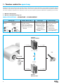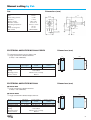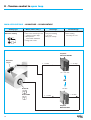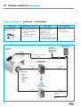
1
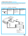
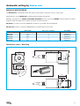
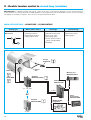
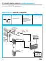
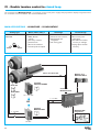
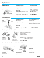
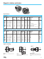
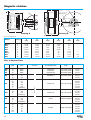
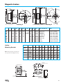
WARNER
ELECTRIC
WARNER
ELECTRIC
Tension
Control
Systems
Max Lamb GmbH & Co. KG
Am Bauhof
97076 Würzburg
Tel. 0931 / 2794 – 0
Fax. 0931 / 274557
email: [email protected]
Tension Control Systems
WARNER ELECTRIC offers the most
complete product line dedicated to
the TENSION CONTROL MARKET. The
long experience in the market led us to
develop high performance controls able to
operate in open and closed loop with
brakes. WARNER ELECTRIC
electromagnetic brakes find an optimum
use in tension control when associated with
the new digital control line.
ABOUT THIS CATALOGUE
This master catalogue groups all
the solutions / products that
WARNER ELECTRIC offers. An
important part is dedicated to the
solution design with particular
consideration regarding the
machine and the tension control
installed. This should help you for
the right solution choice taking in
consideration the results you want
to achieve. All the product
characteristics and dimensions are
included for every product.
Applying the appropriated
Tension Control will lead you
■ To improve quality of the
operation
■ To increase the production
■ Finally to lower your production
cost
CONTACT WARNER ELECTRIC
FOR ANY ASSISTANCE YOU
REQUIRE
www.warnerelectric-eu.com
2
Index
Pages
SYSTEM CONFIGURATIONS
System configuration 1
System configuration 2
System configuration 3
Open loop solutions
Closed loop solutions
TENSION CONTROL IN OPEN LOOP
I.a
I.b
II
III
- Manual setting by pot.
- Manual setting by following arm
- Automatic setting by diameter reading
- Automatic setting by diameter reading with additional functions
TENSION CONTROL IN CLOSED LOOP
I
II
III
IV
- Single roll tension control, automatic setting by dancer arm
- Double roll tension control, automatic setting by dancer arm (modular)
- Double roll or splicer tension control, automatic setting by dancer arm (compact)
- Double roll or splicer tension control, automatic setting by load cells
BRAKES AND CLUTCHES RANGE
Brakes and clutches models
ELECTROMAGNETIC BRAKE TYPE TB
4
4
4
5
6
7
8
8-9
8-9
10-11
12-13
14
14 - 17
18-19
20-21
22-25
26
26
28
Tension brake sizing
TB brake characteristics
Tension brake for strapping machine
27
28 - 31
32 -33
MAGNETIC PARTICLE CLUTCHES AND BRAKES
34
Design and operation
Selection
Applications
Dimensions and specifications
Current regulator power supply for powder brakes
MAGNETIC CLUTCHES AND BRAKES
Design and operation
Applications
Dimensions and specifications
DATA APPLICATION FORM
Material tension data
Calculation dates form
34 - 35
36 - 37
38 - 39
40 - 41
42
43
43
44
45 - 50
51
51
52 - 53
3
System configurations
Analysing and preparing a project in tension control requires good analysis support. The general block diagrams below
are a good representation of any machine generally supporting tension control. We recommend using these diagrams or
a part of it in any discussion and correspondence in order to be clear and to avoid possible misunderstandings.
The tension area in an unwinding system is defined by places where we want to control this tension
SYSTEM CONFIGURATION 1
In single roll unwinding, we have one area tension between A and B. One brake can be easy installed in A. The brake control
system selected will be according to the accuracy required: open loop or close loop.
ZONE 1*, Typical characteristics
(unwind)
Zone 1
A
B
❐
❐
❐
❐
❐
❐
X
Tension zone definition: A-B
Speed point in B
Variable roll rotation speed
Variable inertia
In general constant tension X
Brake system applicable
SYSTEM CONFIGURATION 2
Most usual configuration with driving roll,a rewinder and an unwinder.2 separate tension area with tension could be different in X and in Y.Regarding accuracy required we will choice open loop or close loop.
In A, unwinding brake, in B motor for the speed and in C clutch or moto-reducer for rewinding.
Zone 1
A
X
4
B
Zone 3
Y
Zone 3*, Typical characteristics
(rewind)
C
❐
❐
❐
❐
❐
❐
Tension zone definition B-C
Speed point in B
Variable roll rotation speed
Variable inertia
Constant or Taper tension Z
Particle brake system
applicable
System configurations
SYSTEM CONFIGURATION 3
More complicated machine with intermediary tension area between winder and unwinder.The intermediary area give the line
speed. A master-slave system with speed difference in area B/C give required tension.
All tension systems must be according the speed line in close loop.
B
A
Zone 1
X
C
Zone 2
Zone 3
Y
Z
IMPORTANT CONSIDERATION
D
ZONE 2*, Typical characteristics
In every machine the speed point location must be clearly identified. In general
one of driving nip roll is choose to set the linear speed. The machine speed is
considered as MASTER function. The tension control, whatever the selected
solution, works in SLAVE mode. Practically, the operator sets the machine
speed with a simple potentiometer and all tension control system existing on
the machine have to follow, keeping the required tension at any speed and
during all transitory speed phases.
*NOTE : Each zone is individually controlled. Tension may be different in each zone. It is
assumed that there is no slipping on the nip roll.
❐
❐
❐
❐
❐
❐
Tension zone definition B-C
Speed point in B or C
Constant roll rotation speed
Constant inertia
In general constant tension Y
Brake system applicable
5
System configurations
OPEN LOOP CONFIGURATION
Working in open loop requires an external reference setting applied to the driver. The torque applied to the unwind roll
has to vary according to the diameter of the roll. We don’t control acceleration, deceleration and emergency stop as the
sensor is blind regarding the band tension.
Application needs one sensor only which drives an amplifier without return information for the influence of
correction.
Sensor
Amplifier
Brake
OPEN LOOP SOLUTION
Manual setting by pot.
8 9
Pot.
Amplifier
Brake
Amplifier
Brake
Amplifier
Brake
10 11
Amplifier
Brake
12 13
Manual setting by following arm
8 9
Pot.
Automatic setting by diameter reading
Ultrasonic
sensor
Automatic setting by diameter reading
with additional functions
Ultrasonic
sensor
Additional
functions
6
System configurations
CLOSED LOOP CONFIGURATION
Working in close loop needs one sensor. This one will measure directly or indirectly the band tension. Tension variations
detected by sensor are sent to the brake through the control. This action corrects the variation and the new corrected sensor value is sent to the brake and so on.
Give a accurate tension regulation during acceleration, deceleration, emergency stop.
Sensor
Amplifier
Brake
Position regulation by dancer arm
14 21
This is an electromechanical system and the building quality for the dancer
arm must be verified. The band tension is created by the roll weight and/or
by pneumatic actuator which have sensible air exhaust.
Regulation by load cell
22 23
This is an electromechanical system and the quality of load cells mounting
must be checked. The band influences directly the load cells or loads cells.
The load cells choice and the mounting are very important regarding overload during starting or emergency stop.
Splicer system regulation
Our control systems are used with double roll unwinders with splicer. The 2 brakes are always controlled, when one is in
regulation, the other has holding function through numeric control range MCS2000. These controls include loop control
with PID, a lot of options and are able
to be programmed by PC (via RS232
22 23
line) or by external programmer pocket (visual function)
A
B
The PID function is optimised for one inertia value. The MCS2000 line is inclusive of an important feature namely the PID
correction. Based on the available diameter information you can apply a continuous PID correction. When no information
is available, an internal PID change can be programmed.
PID relative values
100%
P
I
50%
D
Diam. Info
Core
Each parameter P, I and D can be set individually for the smallest
(core) and biggest diameter. As soon as the correct parameters are
found for the extreme diameter value, they are stored. The diameter
information provided will fix the PID values for the present diameter
value. This will allow the system to keep an excellent stability during
the whole diameter evolution. In the case where the diameter information is not available we can provide this signal by installing a
sonic sensor or by working with internal correction. The external
diameter information supplied to the controller will ensure a better
precision compensation compared to an internal correction.
Typical PID values for TB brakes
7
I - Tension control in open loop
Working in open loop requires that a torque setting is defined. The choice depends on the machine complexity and the
automation required. One important factor that remains is the tension precision. For unwind and rewind systems the diameter ratio will play an important role. Working in open loop also requires special considerations regarding system inertia.
a
b
Manual setting by pot.
Manual setting by following arm
MAIN APPLICATIONS - ADVANTAGE – DISADVANTAGE
Setting type
By Pot.
Where, When, Why ?
Advantage
❐ Cable machine
❐ No fast accel/deccel
❐ Low roll diameter ratio
❐ Operator intervention
admitted
Diameter
reading
❐ Low cost solution
❐ Easy to start-up
❐ Automatic regulation by diameter
following arm
❐ Manual correction
feasible
Disadvantage
❐ Tension precision
depends
on operation
❐ For diameter
following arm,
accuracy according
the roll geometry
Amplifier
MCS2000-PSDRV
0 - 24 VDC
0 - 10 VDC
100 - 260 VAC
Pot.
or
Brake TB
28 31
Brake MPB
24 VDC
34 41
0 - 24 VDC
0 - 10 VDC
Amplifier
MCS2000-DRV
8
Manual setting by Pot.
Dimensions (mm)
50 ±0,5
6
20,4
15
10 k Ω
Linear
0,4 W
+ 20%
280° +20°
300° ±5 %
-25°C to +70°C
ø6 mm
10 mm
B90-26325C
Resistance value
Type
Power rating at 40°C
Tolerance
Electric rotation
Mechanic rotation
Operating temperature
Shaft
Panel mounting hole
Part number
25,2
Pot.
4
1,1 x 0,45
18,2
MCS2000-PSDRV
Wiring
Setting
Mounting position
Service manual
Power supply /
Output voltage /
current
current
100 – 260 VAC
0-24 VDC/1,4 A
Shielded cable
Anti-residual
Vibrations free, vertically
MC517
ELECTRICAL AMPLIFIER MCS2000
75
183
174
165
Electrical
input signal
0 – 10 VDC
3,9
Dimensions (mm)
❐ 1 alternative/continue current supply card
❐ 1 logic card with 2 individual channels
(1 fixed, 1 with calibration)
Model
10
149
ELECTRICAL AMPLIFIER MCS2000-PSDRV
8
60
Dimensions (mm)
MCS2000-DRV
❐ 1 logic card with 2 individual channels
(1 fixed, 1 with calibration)
MCS2000-DRV8
❐ 1 logic card with 8 individual output channels
Power supply /
Output voltage /
current
current
24 VDC/3 A
0-24 VDC/1,4 A
24 VDC/3 A
0-24 VDC/0,3 A per channel
Shielded cable
Anti-residual
Vibrations free, vertically
MC517
183
149
MCS2000-DRV
MCS2000-DRV8
Wiring
Setting
Mounting position
Service manual
Electrical
input signal
0 – 10 VDC
0 – 10 VDC
174
165
Model
75
60
9
II - Tension control in open loop
MAIN APPLICATIONS - ADVANTAGE – DISADVANTAGE
Setting type
Diameter reading
Where, When, Why ?
Advantage
❐ The most commonly used
solution in open loop
❐ No operator
intervention admitted
❐ Large roll ø ratio
❐ Physical reading,
no reset
❐ Easy to start-up
Disadvantage
❐ Poor reading
accuracy on core
Amplifier
MCS2000-PSDRV
Ultrasonic
sensor
0 - 24 VDC
0 - 10 VDC
100 - 260 VAC
or
Brake TB
24 VDC
28 31
Brake MPB
0 - 24 VDC
0 - 10 VDC
34 41
Amplifier
MCS2000-DRV
10
Automatic setting by diameter reading
ULTRASONIC SENSORS
SCUA-140
SCUA-130
15 to 30 VDC / max 30 mA
100 mm
1000 mm
±1 mm
IP67
5 m cable
MC487
SCUA-140
15 to 30 VDC / max 30 mA
400 mm
2400 mm
±1 mm
IP67
5 m cable
MC488
Dimmensions (mm)
23
14,2
ø44,5
65
30°
20
4,3
4,6
60
95
10
5
M12x1
11,2
18,5
15 15
M12x1
31
30
M30x1,5
SCUA-130
SCUA-140
Dimensions (mm)
❐ 1 alternative/continue current supply card
❐ 1 logic card with 2 individual channels
(1 fixed, 1 with calibration)
MCS2000-PSDRV
Wiring
Setting
Mounting position
Service manual
ELECTRICAL AMPLIFIER MCS2000
60
Dimensions (mm)
MCS2000-DRV
❐ 1 logic card with 2 individual channels
(1 fixed, 1 with calibration)
Model
MCS2000-DRV
MCS2000-DRV8
Wiring
Setting
Mounting position
Service manual
Electrical
input signal
0 – 10 VDC
0 – 10 VDC
Power supply /
Output voltage /
current
current
24 VDC/3 A
0-24 VDC/1,4 A
24 VDC/3 A
0-24 VDC/0,3 A per channel
Shielded cable
Anti-residual
Vibrations free, vertically
MC517
75
174
165
MCS2000-DRV8
❐ 1 logic card with 8 individual output channels
149
Power supply /
Output voltage /
current
current
100 – 260 VAC
0-24 VDC/1,4 A
Shielded cable
Anti-residual
Vibrations free, vertically
MC517
183
174
165
Electrical
input signal
0 – 10 VDC
75
183
149
ELECTRICAL AMPLIFIER MCS2000-PSDRV
Model
70
SCUA-130
Model
Power supply
Min. distance
Max. distance
Accuracy
Protection class
Accessory
Service manual
60
11
III - Tension control in open loop
MAIN APPLICATIONS - ADVANTAGE – DISADVANTAGE
Setting type
Diameter reading
Where, When, Why ?
Advantage
❐ The most commonly used
solution in open loop
❐ Operator
intervention admitted
❐ Large roll ø ratio
Disadvantage
❐ Physical reading,
❐ Poor reading
no reset
accuracy on core
❐ Easy to start-up
❐ Graphic display for output
percentage value
❐ Functions control available
remote/manually by operator
MCS2000-POT
OPTION for
MCS2000-DRV :
MCS2000-PS
Power supply
+24VDC
Ultrasonic
sensor
Ultrasonic sensor signal
0 - 10 VDC
Amplifier
MCS2000-PSDRV
0 - 10 VDC
0 - 24 VDC
Brake TB
100 - 260 VAC
28 31
Brake MPB
or
34 41
Amplifier
MCS2000-DRV
0 - 10 VDC
0 - 24 VDC
Additional control
signals
24 VCC
12
Fast Stop, Hold
Brake OFF
Automatic setting by diameter reading
Ultrasonic sensors - Dimensions, see page 7
SCUA-130
Model
Power supply
Min. distance
Max. distance
Accuracy
Protection class
Accessory
Service manual
SCUA-140
SCUA-130
15 to 30 VDC / max 30 mA
100 mm
1000 mm
±1 mm
IP67
5 m cable
MC487
SCUA-140
15 to 30 VDC / max 30 mA
400 mm
2400 mm
±1 mm
IP67
5 m cable
MC488
Ultrasonic Diameter Sensing – MCS2000-POT
❐ A simple, analogue, open loop torque control.
❐ Power supply 24 VDC / Internal consumption 150 mA.
❐ Adjustable maximum level of the output signal relatively to the
ultrasonic input level.
❐ Graphic display of the output level – full screen equal 10 VDC.
❐ FAST STOP, HOLD and BRAKE OFF can be activated either
through the front switches or through the terminal bloc.
❐ FAST STOP and HOLD levels are adjustable via potentiometer.
❐ FAST STOP: a ratio of 1 to 10 times to OPERATING LEVEL
❐ OPERATING LEVEL: maximum 10 VDC divided by the FAST
STOP ratio.
❐ HOLD: output level adjustable between 0 and 10 VDC
To be used ONLY with scalable ultrasonic sensors type SCUA-130
(1 m) or SCUA-140 (2.5 m)
Mounting and dimensions (mm)
Overall dimensions maximum:
Height
160 mm
Width
95 mm
Depth
75 mm
Weight
0,350 kg
❐ Service manual : MC520
ELECTRICAL AMPLIFIER MCS2000
MCS2000-PSDRV
MCS2000-DRV
MCS2000-DRV8
Wiring
Setting
Mounting position
Service manual
Electrical
input signal
0 – 10 VDC
0 – 10 VDC
0 – 10 VDC
Power supply /
Output voltage /
current
current
100 – 260 VAC
0-24 VDC/1,4 A
24 VDC/3 A
0-24 VDC/1,4 A
24 VDC/3 A
0-24 VDC/0,3 A per channel
Shielded cable
Anti-residual
Vibrations free, vertically
MC517
MCS2000-DRV8
❐ 1 logic card with 8 individual
output channels
Dimensions (mm)
75
183
149
Model
MCS2000-DRV
❐ 1 logic card with 8 individual
output channels
174
165
MCS2000-PSDRV
❐ 1 alternative/continue current supply card
❐ 1 logic card with 2 individual channels
(1 fixed, 1 with calibration)
60
13
I - Simple tension control in closed loop
If your machine requires a very accurate web tension control, then you need to work in closed loop. An important unit in
the loop is the sensor. Several possibilities are offered. The choice now depends on the kind of machine you are
building, the mechanical construction and the max tension value you desire to control.
MAIN APPLICATIONS - ADVANTAGE – DISADVANTAGE
Setting type
Dancer arm
Where, When, Why ?
❐ Printing machines
❐ Intermittent function
❐ Flying splice need
Advantage
❐ Absorb tension peak
❐ Can act as store
❐ Easy flying splice
❐ Accel / decel machine
phase well absorbed
❐ Flexibility
Disadvantage
❐ Need more space
❐ Moving parts
Sensor
MCS605-E
110/230 VAC
Dancer
arm
Analogue
Control
MCS202-E
Brake TB
28 31
Brake MPB
34 41
0 - 24 VDC
Additional functions
❐
❐
❐
❐
14
Brake open
Emergency stop
Drift stop(stop integral term of PID)
Gain change
Automatic setting by dancer arm
ROTARY SENSOR MCS605-E (see pages 16 and 17)
ANALOGUE CONTROL MCS202-E
❐ MCS202-E1
Standard execution
❐ MCS202-E54
Standard IP54 protected
❐ MCS202-EC1
Open frame execution
Technical characteristics – valid for 3 executions
Range - Values
110-220 VAC selectable
Max 2, 5 Amps, short circuit protected
Loop gain
Offset torque
0-24 VDC
Metal rugged housing
2 adjustable range selection
MCS-KIT1, 2, 3, 5 and 6
Dancer arm with MCS605-E
MC403
Power supply
Output current capability
User settings
Output voltage brakes
Housing
Loop gain
Accessories
Sensor compatible
Service manual
Comments
Open front face to access
Able to power 2 TB in parallel
Front face potentiometer
Front face potentiometer
Compatible all elec. Warner Electric
Only MCS202-E1 and –E54
Can be change during operation
See details on page 17
See details on pages 16 and 17
Technical information
MCS202 control is based on classical and fixed PID terms. The loop gain can be set on front face potentiometer. Due to
the fixed PID terms, its use is limited in terms of roll diameter ratio. One input is provided to change the loop gain and has
to be used when diameter ratio exceeds 8. To ensure proper operation it is important to wire the function “Drift Stop”. This
function releases the Integral term as soon as the machine runs.
99
37
29
Dimensions (mm)
51,5
73
60
87
282
265
MCS 202-E
LOOP GAIN
14,3
BRAKE
TORQUE OFFSET
ø65
57
120
POWER
15
Automatic setting by dancer arm
ROTARY SENSOR MCS605-E
A position sensor is used in 2 possible ways:
❒ - To detect dancer moving in the closed loop installation working on dancer principle.
❒ To sense the diameter of the roll to operate open loop control or make PID compensation in closed loop installation.
Power supply
Max. detection angle
Sensitivity
Service manual
MCS605-E
10 to 30 VDC / 30 mA
(or ± 5 to 15 VDC)
200° or ± 100°
2,5 mV / V / °
MC483
ELECTRICAL CONNECTIONS
CONNECTOR
CABLE
– Supply
White
3
+15 V
2
Green Signal
4
+ Supply
Brown -15 V
1
Shield
Signal
View from outside
Sensor
Working in closed loop with the arm dancer principle is very
popular especially in the printing market where a good flexibility of the system is required to absorb the eventual “tension peaks”. The rotary sensor is necessary to read the dancing roll movement.
MCS605-E is ideal for easy mounting. It is encapsulated in
rugged metal housing preventing mechanical shocks.
Furthermore it is provided with built in switch in order to
change the signal output polarity.
TB brake
16
Automatic setting by dancer arm
MCS605-E ACCESSORIES
The MCS202-Exx is designed to work with dancer arm principle. Usually the sensor is a rotary type.
Warner Electric sensor MCS605-E are delivered with complete mounting kit.
Mounting kit comprises of CABLE, COUPLING, BRAKETS and all necessary SCREWS. Various KITS have various
lengths of cable and cable with or without connector at control end side.
MCS2000 line requires free leads (MCS2000 control line is provided with terminal block).
MCS202-Exx requires a connector (MCS202-Exx is provided with the connector).
Cable length
3m
3m
4,5 m
4,5 m
6m
8m
MCS-KIT1
MCS-KIT2
MCS-KIT3
MCS-KIT4
MCS-KIT7
MCS-KIT8
One / Two connectors
2
1
2
1
2
1
Compatible
MCS202-Exx
MCS2000
MCS202-Exx
MCS2000
MCS202-Exx
MCS2000
Dimensions (mm) – Mounting
130
50,8
min 47 / max 70
18
57
ø6,35
65
Coupling
3x1
20°
57
31,6
ø38,1
45
14,2
38,1
21,9
ø6,5
3 x ø45
17
II - Double tension control in closed loop (modular)
MCS2000-ECA is a digital controller that can be used in both open or closed loop. Operation in open and closed loop
is also possible. It is mainly destined for OEM application. The programming tool is detachable. Sensor, sensor mounting
kit, display are available as options. The unit has to be powered with 24 VDC.
MAIN APPLICATIONS - ADVANTAGE – DISADVANTAGE
Setting type
Dancer arm
Where, When, Why ?
❐ Printing machines
❐ Intermittent function
❐ Flying splice need
Advantage
❐ Absorb tension peak
❐ Can act as store
❐ Easy flying splice
❐ Accel / decel machine
phase well absorbed
❐ Flexibility
Disadvantage
❐ Need more space
❐ Moving parts
Sensor
MCS605-E 16 17
Dancer
arm
Brake TB
Memory card
MCS2000-CRD-2
28 31
Amplifier
MCS2000-PSDRV
Brake MPB
11
34 41
Controller
MCS2000-ECA
100 - 260 VAC
0 - 10 VDC
or
Hand
Programmer
MCS2000-PRG
Amplifier
MCS2000-DRV
24 VDC
18
11
MCS2000-WIN
programme
Automatic setting by dancer arm
ELECTRICAL AMPLIFIERS MCS2000-PSDRV and MCS2000-DRV (see page 9)
ROTARY SENSOR MCS605-E (see pages 16 et 17)
CONTROLLER MCS2000-ECA
❐ Digital controller - 2 channels
Main Characteristics
❐
❐
❐
❐
❐
❐
❐
❐
❐
❐
❐
❐
24 VDC power supply unit
PID parameters setting on line
Automatic adaptation for PID parameters, splicing logic included
Opto isolation for input and output
Compatible PLC
Automatic sensor scaling and output sensor information
Programming easy by pocket keyboard or PC(Windows)
Available in open loop as calculator
2 analogic input, 2 output channels
Plugable memory card
Three language available
Most dedicated for unwinding and rewinding with electromagnetic
brakes and clutches.
❐ Service manual : MC514
MCS2000-PRG - HAND PROGRAMMER
❐
❐
❐
❐
❐
4 command keys only
2 x 16 characters display
Menu in 3 languages
Connectable and disconnectable during operation
Supply by control MCS 2000-EC
MCS2000-CRD-2 - MEMORY CARD
All setting data saved. It allows a quick loading operation on new machine
or on running machine to optimise.
❐ Memory for 2 different programs
❐ Plugable on line in MCS2000-ECA unit
MCS2000-WIN – PROGRAMME
The program can modify the running setting by this software running with:
Windows 95/98/XP/2000.
19
III - Double tension control in closed loop (compact)
The command unit MCS2000-CTDA is a complete solution with power supply and programmer display integrated. There
are 2 software version available. See technical data below
MAIN APPLICATIONS - ADVANTAGE – DISADVANTAGE
Setting type
Dancer arm
Where, When, Why ?
❐ Printing machines
❐ Intermittent function
❐ Flying splice need
Advantage
❐ Absorb tension peak
❐ Can act as store
❐ Easy flying splice
❐ Accel / decel machine
phase well absorbed
❐ Flexibility
Disadvantage
❐ Need more space
❐ Moving parts
Sensor
MCS605-E 16 17
Dancer
arm
Brake TB
Memory card
MCS2000-CRD-2
28 31
Amplifier
MCS2000-PSDRV
Brake MPB
11
34 41
Controller
MCS2000-CTDA
100 - 260 VAC
0 - 10 VDC
or
Amplifier
MCS2000-DRV
24 VDC
20
11
MCS2000-WIN
programme
Automatic setting by dancer arm
ELECTRICAL AMPLIFIERS MCS2000-PSDRV and MCS2000-DRV (see page 9)
ROTARY SENSOR MCS605-E (see pages 16 et 17)
CONTROLLER MCS2000-CTDA
Specifications
Input power supply
110-240 VAC selectable
Analogue inputs
Two analogue inputs
0-10 VDC
Analogue outputs
Two controlled channels
Open loop signal
± 10 VDC, 0-20 mA
0-10 VDC
Digital inputs
Set point change +
Set point change –
Set point change ±
active low
active low
front face switch
Gain multiplier
Output limitation
ABC binary combination
ABC inputs synchronisation
Stop integral form
active low
active low
active low
active low
active low
Digital outputs
Sensor level indication
Two binary outputs
Main features
❐
❐
❐
❐
❐
❐
❐
❐
❐
❐
❐
❐
❐
❐
Three mounting possibilities
Software password protected
Scrolling menu program
Multipurpose application
RS232 communication
Two ouput channels
Automatic sensor scaling
Programmable output configuration
Output sensor information
External set point change
Automatic or imposed PID correction
All features requested for tension control
Plugable memory card
Variable tension value to prevent telescopic effect on
unwinding – CTDA-22
❐ Service manual : MC525
Other outputs
Power supply sensor
Power supply
Voltage reference
± 15 VDC / 100 mA
± 5 VDC / 100 mA
24 VDC
+ 10 VDC / 10 mA
MCS2000-CRD-2 - MEMORY CARD
All setting data saved. It allows a quick loading operation on new machine
or on running machine to optimise.
❐ Memory for 2 different programs
❐ Plugable on line in MCS2000-ECA unit
MCS2000-WIN – PROGRAMME
The program can modify the running setting by this software running with:
Windows 95/98/XP/2000.
21
IV - Double tension control in closed loop
The command unit MCS2000-CTLC is a complete solution with power supply and programmer display integrated. There
are 2 software version available. See technical data below
MAIN APPLICATIONS - ADVANTAGE – DISADVANTAGE
Setting type
Load cell
Where, When, Why ?
❐ Slitter, Sheeter
Coater
❐ For heavy material
❐ Limited room
❐ No fast accel/decel
❐ Tension peak accepted
Advantage
❐ Direct tension measure
❐ Mechanically well
integrated
❐ No moving part
Disadvantage
❐ No tension peak
absorption
❐ Accel/decel machine
not easy to manage
❐ Flying splice function
not easy
One or two load cells
Memory card
MCS2000-CRD-2
Amplifier
MCS2000-PSDRV
Brake TB
11
28 31
Controller
MCS2000-CTLC
Brake MPB
34 41
100 - 260 VAC
0 - 10 VDC
or
Amplifier
MCS2000-DRV
0 - 24 VDC
11
0 - 24 VDC
24 VDC
22
MCS2000-WIN
Programme
Automatic setting by load cell
ELECTRICAL AMPLIFIERS MCS2000-PSDRV and MCS2000-DRV (see page 9)
CONTROLLER MCS-2000-CTLC
Specifications
Input power supply
110-240 VAC selectable
Analogue inputs
Two analogue inputs
0-10 VDC
Analogue outputs
Two controlled channels
Open loop signal
± 10 VDC, 0-20 mA
0-10 VDC
Digital inputs
Set point change +
Set point change –
Set point change ±
active low
active low
front face switch
Gain multiplier
Output limitation
ABC binary combination
ABC inputs synchronisation
Stop integral form
active low
active low
active low
active low
active low
Digital outputs
Sensor level indication
Two binary outputs
Main features
❐
❐
❐
❐
❐
❐
❐
❐
❐
❐
❐
❐
❐
❐
Three mounting possibilities
Software password protected
Scrolling menu program
Multipurpose application
RS232 communication
Two ouput channels
Automatic sensor scaling
Programmable output configuration
Output sensor information
External set point change
Automatic or imposed PID correction
All features requested for tension control
Plugable memory card
Service manual : MC525
Other outputs
Power supply sensor
Power supply
Voltage reference
± 15 VDC / 100 mA
± 5 VDC / 100 mA
24 VDC
+ 10 VDC / 10 mA
MCS2000-CRD-2 - MEMORY CARD
All setting data saved. It allows a quick loading operation on new machine
or on running machine to optimise.
❐ Memory for 2 different programs
❐ Plugable on line in MCS2000-ECA unit
MCS2000-WIN – PROGRAMME
The program can modify the running setting by this software running with:
Windows 95/98/XP/2000.
23
Load cells
The FOOT MOUNTED LOAD CELL is the ideal solution to retrofit machines or for heavy tension measurement. The
foot mounted model has to be installed with a pillow block type ball bearing supporting the sensing shaft. FM01A... and
FM02-... are only differenciated by the physical dimensions.
FOOT MOUNTED TYPE FM01A… and FM02-…
Foot mounted load cells are available in two versions:
With incorporated amplifier : FM……..-AC
AC = amplifier and connector on the load cell body
Without amplifier :
FM……..-C
C = connector on load cell body
Specifications (all FM series)
Power supply
Sensitivity
Rating
Connections
Permitted overload
- Compression
- Extension
Radial permitted force
Dimensions
Mounting
Service manual
FM……..-AC
FM……..-C
±12 to ±15 VDC
± 5 VCC or +10 VDC
0-5 VDC, nominal load
10 mV, nominal load
100 – 250 – 500 – 1000 – 2500 – 5000 – 10000 N
Cable supplied
150 %
120 %
50%
See mounting instructions ref. MC480
See recommendations on page 25
MC480
AVAILABLE MODELS / CAPACITY
Nominal load
100 N
250 N
500 N
1000 N
2500 N
5000 N
10000 N
FM01AFM01AFM02..FM02..-
-100-AC
-100-C
-250-AC
-250-C
-500-AC
-500-C
-1000-AC
-1000-C
-2500-AC
-2500-C
-5000-AC
-5000-C
-5000-AC
-5000-C
-10000-AC
-10000-C
24
Load cells
END SHAFT LOAD CELLS are normally used in new machines designed with the possibility to place the load cell
directly on the sensing roll. The end shaft version offers the advantage of being able to easily place the load cell in any
tension resultant direction. The ES model exists in two versions differenciated with the diameter of ball bearing which has
to be placed in.
All end shaft load cells are based on the Wheatstone bridge principle. They have no built in amplifier. They are delivering a
signal which is proportionnal to the voltage supply and tension applied. It is important to respect the measurement
direction referenced on the load cell body (normally an arrow indicates the sensitive direction).
ES..-... LOAD CELL FEATURES
Power supply
Sensitivity
Rating
Connections
Mechanical overload
Dimensions
Mounting
Service manual
ES01-40C and ES02-52C
10 to 15 VDC / 40 mA (±5 VDC in Warner Electric control)
2 mV / V supply at nominal load
1 mV / V supply for 50 and 150 N models
50-150-250-500-1000-2000 N
5 m shielded cable supplied
Max 150 % in any direction
See mounting instructions ref. MC481 and MC482
See recommendations below
MC481 and MC482
AVAILABLE MODELS / CAPACITY
Nominal load
50 N
150 N
250 N
500 N
1000 N
2000 N
ES01-...
ES02-...
-50-40C
-
-150-40C
-
-250-40C
-250-52C
-500-40C
-500-52C
-1000-40C
-1000-52C
-2000-40C
-2000-52C
LOAD CELLS SIZING - MOUNTING RECOMMENDATIONS
Please keep this principle in mind: the load cell installed is destined to measure the
WEB TENSION and not other constraints applied to it.
Wrapping
Angle
240° min.
Take the following points into consideration before selecting, sizing and installing material components.
❐ Load cells location should be vibration free. Vibrations will decrease quality measurement.
❐ The sensing shaft fitted on or in has to be very well balanced. Unbalanced shaft will create measurement oscillation,
causing variations in control quality.
❐ Adapted ball bearing have to be used to avoid original stress on load cell (self-aligning ball bearing).
❐ Respect a reasonable sensing shaft weight/web tension measure ratio. Less than 1.
❐ Do not oversize the load cell respect to your calculation. Max admitted factor 3, recommended 1,5.
❐ Respect a minimum wrapping angle on load cell. Min = 240°.
❐ So far as it is possible, use load cell in compression, with web tension effect in same direction as the weight of shaft.
25
Tension brakes and clutches range
Brake and clutch
types
Series
Main characteristics
Torque range
Electromagnetic brakes
TB
Monodisc
24 VDC power supply
0,5 - 300 Nm
Size
170
260
425
500
Electromagnetic brakes
825
1000
1225
1525
28 31
Monodisc
24 VDC power supply
TBM
Size 10
Pages
10 Nm
32 33
Magnetic particle brakes
Magnetic particle clutches
Permanent magnetic brakes
MPB
Size
2
15
70
120
240
Completely packaged
and enclosed unit
Shaft output
24 or 90 VDC power supply
0,04 - 27 Nm
MPC
Size
2
15
70
120
Completely packaged
and enclosed unit
Both end shaft output
24 or 90 VDC power supply
0,04 - 13,2 Nm
MB
Completely packaged
and enclosed unit
Shaft output
Manual setting
0 - 33 Nm
Completely packaged and
enclosed unit
Bore output
Manual setting
0,07 Ncm - 33 Nm
Size
1
1,5
2
3
4
Permanent magnetic clutches
MC
Size
1,5
2
3
4
26
5
5,5
6
9
5
5,5
6
9
34 41
34 42
43 50
43 50
Tension brake sizing
Two important parameters are used in brake selecting:
❐ Max. torque requirement
❐ Max. thermal power to be dissipated
These two values are determined by the application (see calculation example on pages 52-53).
ELECTROMAGNETIC BRAKE TYPE TB – SELECTION
TB brake selection is based on two values :
Max torque need (Nm) on the brake
*Max brake rotation speed for the max torque (rpm)
* As the curve given for TB selection takes the power dissipation into account, this value is used.
Tmax = torque needed at the brake for the max
tension in material and the max roll diameter taking any gear ratios into account.
Tmax
Selection point
Nmax = brake rotation speed for the max linear
speed and the max roll diameter – taking any
gear ratios into account.
N max
Note : the constant tension in the web gives a
constant power on the brake. However, we
make the selection for the max torque (then at
full roll diameter) because it’s the moment
where the brake has the least natural cooling.
Gear box
Speed
Brake
Torque
27
TB brake selection
The table (pictured below left) illustrates the selection of the correct TB brake. The table on the right determines the maximum torque provided by the brake when nominal voltage is applied. After selection you can consult the complete brake
characteristics and dimensions on pages 30 to 31.
Dynamic braking torque
TB170 - TB1525
400
500
300
400
TB 15
200
300
TB 122
TB
TB 10
00
60
TB 825
40
30
TB 500
20
150
Brake torque MB [Nm]
25
25
12
TB 1000
200
15
TB
100
80
25
5
150
Torque Md [Nm]
Maximum braking torque (emergency stop)
TB170 - TB1525
100
80
TB 825
60
50
40
TB 500
30
15
10
20
8
15
TB 425
TB 425
6
10
4
8
3
6
5
2
1,5
TB 260
4
TB 260
3
1
0,8
2
0,6
0,4
1
TB 170
0,3
0,6
0,2
10
20
15
40
30
60 100
200
400
50 80
150
300 500
Brake n (rpm)
28
TB 170
0,8
0
100
200
300
Brake n (rpm)
400
500
TB brake characteristics
TB units are assembled using various parts described below. Main components of the brake are armature and magnet.
Additional parts are offered to provide for ease of mounting.
Part
1
2
Armature hub*
Armature
3
Magnet 24V
4
Terminals
TB170
TB260
TB425
D = 46 mm
B5102-541-001-38
K110-0096
K375-631-012
R = 110 Ω, 20°C
Wires
D = 69 mm
B5103-541-001-47
K110-0097
K5365-631-016
R = 60 Ω, 20°C
B5103-101-002
D = 111 mm
B5104-541-001-31
K110-0098
K5367-631-008
R = 76 Ω, 20°C
B5103-101-002
1
2
3
4
5
5-1
6
7
* Prebored
** Indicate bore and keyway
Part
Part
D = 130 mm
Taperlock bushing** B180-xxxx-xxxx
Armature hub
K5300-541-004
Armature
B110-0047
K5300-101-003
Drive pins
3x
Magnet IM 24V
B5300-631-040
Terminals
B5311-101-001
Magnet OM 24V
B5300-631-000-46
Conduit box
K5200-101-010
TB825
TB1000
TB1225
TB1525
D = 259 mm
B180-xxxx-xxxx
B540-0313
B5302-111-021
B5301-101-001
3x
B5312-631-000-36
R = 20 Ω, 20°C
B5311-101-001
-
D = 316 mm
B180-xxxx-xxxx
B540-0015
B5303-111-011
B5301-101-001
4x
B5313-631-000-11
R = 22 Ω, 20°C
B5311-101-001
-
D = 395 mm
B180-xxxx-xxxx
B540-0314
B5304-111-005-04
B5301-101-001
4x
B5314-631-000-08
R = 20 Ω, 20°C
B5311-101-001
-
K5200-101-011
K5200-101-011
K5200-101-011
1
2
3
Taperlock bushing**
Armature hub
Armature
4
Drive pins
4
Magnet IM 24V
5-1
6
Terminals
Magnet OM 24V
D = 215 mm
B180-xxxx-xxxx
B540-0394
B5301-111-019
B5301-101-001
3x
B5311-631-000-30
R = 20 Ω, 20°C
B5311-101-001
B5311-631-000-16
7
Conduit box
K5200-101-011
TB500
29
TB brake characteristics
All TB brakes are rated at 24 VDC nominal. When selection is correct the voltage on the brake should be approximately 12 VDC for your maximum parameters used in calculation. All TB brakes are able to work for short periods of
time (less than 10 seconds) in the 12-24 VDC range, for example in machine deceleration or in emergency stop.
Technical data and dimensions
TB170, TB260, TB425
TB500 IM
TB825 IM, TB1000 IM, TB1225 IM
B
A
C
1,6
øG
øD
øH
øM
øL
2,4
K
3,2
øS
øQ
øS
øQ
øG
K
øN
øP
øD
øM
øL
3,2
øN
øG
øS
øQ
K
øD
øH
øL
E
øP
B
ø9,52 ±0,025
3,0
E
0,4
A
T
B
C
A
TB500 OM
Size
Md
Md min
n max
I 24V =
P* Continu
P* Alternativ
R 20° C
tb
Inertia
Mass
A
B
C
øD
E
[Nm]
[Nm]
[rpm]
[A]
[kW]
[kW]
[Ω]
[s]
[kgm2]
[kg]
[mm]
[mm]
[mm]
[mm]
[mm]
TB825 OM, TB1000 OM, TB1225 OM
TB170
TB260
TB425
TB500
TB825
TB1000
TB1225
TB1525
0,8
0
5000
0,22
0,015
0,022
110
0,020
12 • 10-6
0,180
30,5
7
46
20,6
4
0,08
5000
0,40
0,030
0,045
60
0,040
116 • 10-6
0,650
48,5
12
69
32
16,5
0,16
5000
0,32
0,060
0,100
76
0,080
1,4 • 10-3
1,800
52
14
111
30,5
35
0,2
5000
1,010
0,100
0,180
23,8
0,052
1,9 • 10-3
2,3
79
77
51
130
30,5
75
0,5
3000
1,177
0,200
0,360
20,4
0,112
0,022
8,2
94
30,5
54
215
33,5
150
1,1
2400
1,224
0,360
0,650
19,6
0,152
0,041
12
105
30,5
56,5
259
36,5
300
2
2000
1,076
0,520
0,950
22,3
0,290
0,095
21
138
30,5
62
316
41,5
450
3
1600
1,212
0,810
1,580
19,8
0,310
0,213
27,5
116
30,5
65
395
44,5
* Alternativ duty based on 30 minutes ON and 30 minutes OFF.
30
E
F
1,2
TB brake characteristics
TB825 - 1525
øG
øN
øP
2,4
10
9,5
K
øU
30
661-0005
ø12,7
E
C
A
F
øG
øH
K*
øL max
[mm]
[mm]
[mm]
[mm]
[mm]
øM±0,025
[mm]
øN±0,05
[mm]
øP (for screw)
[mm]
øQ-0,05
[mm]
øS (for screw)
[mm]
T
øU
[mm]
[mm]
+0.01
-0
3,5
Size
Steel
< 0,2 % C
M
øD
øM
øH
øL
B
ø12,7 +0.025
0
1/2 -13 UNC-3B
TB1525 IM
Non magnetic
15
TB170
TB260
TB425
TB500
TB825
TB1000
TB1225
TB1525
19,5+0,05
15,9
10,3
10
-
35
30,1
17,5
20
-
62
31,8
22,2
22
-
61,9
54
4 × M4
-
88,9
79,4
4 × M4
-
142,47
127
4 × M6
-
28,5
49
38
32
98,42
3 × 120°
52,40
60,3
8 × M4
165,10
149,2
4 × M10
49
110
55
118
38
42
90,49
3 × 120°
88,93
108
6 × M8
247,62
255,5
4 × M8
170
98
159
44,5
60
133,4
3 × 120°
136,55
155,6
6 × M8
220
114
175
76
75
149,3
4 × 90°
161,95
184,1
6 × M8
260
180
152,5
76
75
215,9
4× 90°
228,60
247,60
12 × M8
340
* Reverse mounting of taperlock bushing is possible
31
Tension brake for strapping machine
Specially designed for strapping machine, the electromagnetic brake TBM10 is adjustable for the different kind of
plastic film. Mounted on the intermediate roller, it will tighten the plastic film and will permit a perfect strapping.
TBM BRAKE
PALLET
PLASTIC FILM ROLLER
TBM SIZE 10
Brake torque
8
M d (Nm)
M d (Nm)
Heat dissipation torque
6
4
3
15
10
8
2
6
5
1.5
4
1
3
10
20
15
40 60 100 200 400
30 50 80
150 300 500
n (rpm)
32
20
0
100
200
300
400
500
n (rpm)
Tension brake for strapping machine
TBM SIZE 10
VAR 03
➀
T
T
500
➁
45°
P9
ø 90
ø 100 h9
ø 42
ø 5.5
D H8
ø 81
➂
4.5
26
D min = 8 mm with standard keyway
D min = 13 mm with standard keyway
3 pins on
ø 57.96
7.9 H8
VAR 04
8.3
➃
T
T
➀
ø 41
ø 0,10
U max : 24 VDC - P 20°C = 10,8 Watts
26
1
2
3
Keway according to : ISO R773 / BS 4235 /
NFE 22175 / tolerance P9
4
Part
TBM TAILLE 10
Inductor 24VDC
Armature VAR03
Hub prebored ø7,5
Hub ø12 H8 + Keyway 4 P9
Armature VAR04
B6650-631-000-39
B110-0000-1358
B540-0000-2519
B540-0000-2517
B6650-111-000-08
33
Magnetic particle clutches and brakes
Accurate torque control with instantaneous engagement!
Warner Electric Precision Tork™
magnetic particle clutches and
brakes are unique because of the
wide operating torque range available. Torque to current is almost linear and can be controlled very accurately.
The unique features of the magnetic
particle clutches and brakes make
them ideal for :
❐
❐
❐
❐
tension control
load simulation
cycling/indexing
soft starts and stops
Specials are our business
Special Shaft Configurations
❐ Customer specified shaft configurations for easy machine mounting
and retrofitting.
Wash Down Environment
❐ Stainless steel units available for
extreme environments.
Special Torque
❐ Maximum torque configurations to
meet customer specifications.
Metric units
❐ On request, regarding quantities
34
Features and Benefits
Torque independent of slip speed
❐ Torque is transmitted through magnetic particle chains which are
formed by an electromagnetic field.
The torque is independent of slip
speed, depending only on circuit
current, and is infinitely variable
from 0 (disengaged) to rated
torque.
Precise engagement
❐ Precision Tork magnetic particle
clutches and brakes engage to
transmit torque with speed and
precision. Response of the particles to the field is virtually instantaneous, providing perfectly controlled, jerk-free engagement.
Customer specified engagement
❐ Engagement time may be very
gradual or extremely fast. The frequency and torque of the engagement/disengagement sequence is
limited only by the capabilities of
the control circuitry.
No wearing parts
❐ There are no friction surfaces to
grab or wear, and the units are not
affected by changes in atmospheric or other environmental conditions.
Efficient/Compact design
❐ High torque to size ratio and low
consumption of electric power.
Versatile mounting
❐ Convenient bolt circle for easy
mounting.
❐ Mounting brackets available for all
sizes.
❐ Brakes are available with solid
shafts and through bore.
❐ Can be mounted horizontally or
vertically to solve virtually any
motion control requirement.
Modular
❐ Customised products
❐ Interchangeable with industry standard sizes
Design and operation
Completely packaged and enclosed unit.
Easy to install
Stainless steel
hardware
Low current coil generates magnetic field
Extremely long
life spherical
magnetic particles
Zinc dichromate
plating on all steel
surfaces
Magnetic
powder cavity
Stainless steel
input shaft
Convenient pilot
and mounting bolt
pattern
New and unique
dual seal design
Operating Principles
The magnetic particle unit consists of
four main components:
1) Housing
2) Shaft/disc
3) Coil
4) Magnetic powder
Engagement
When DC current is applied to the
magnetic particle unit, a magnetic flux
(chain) is formed, linking the
shaft/disc to the housing. As the current is increased the magnetic flux
becomes stronger, increasing the
torque. The magnetic flux creates
extremely smooth torque and virtually
no “stick-slip”.
Torque current curve
120
Percent of rated torque
The coil is assembled inside the
housing. The shaft/disc fits inside the
housing/coil assembly with an air gap
between the two; the air gap is filled
with fine magnetic powder.
100
80
60
Power input (DC)
Stationary field
Magnetic-flux path
Magnetic particles
Rotor
Cylinder
Seal
Output shaft
Input shaft
Field coil
40
Disengagement
20
0
0
20
40
60
80
100
Percent of rated current
120
When DC current is removed the
magnetic powder is free to move
within the cavity, allowing the input
shaft to rotate freely.
35
Magnetic particle clutches and brakes
Selection
Sizing
To properly size magnetic particle clutches or brakes the thermal energy (slip watts) and torque transmitted must be considered. If thermal energy and torque are known for the application, select the unit from the charts to the right.
Speed
V (RPM)* =
Velocity (m/min)
π · ø coil** (m)
* In rewind applications the motor RPM should be higher (10%) than the fastest spool RPM.
** In applications with the web running over a pulley or in a nip roll application use the pulley diameter as the roll
diameter.
Thermal Energy (slip watts)
1- When a brake or clutch is slipping, heat is generated. Heat is described in terms of “energy rate” and is a function of
speed, inertia, and cycle rate.
For continuous slip applications, such as tension control in an unwind or rewind application slip watts are calculated using
the following formula:
Slip Watts =
0,103 · torque (Nm) · speed (RPM)
2- For cycling applications heat is generated intermittently, and is calculated using the following formula:
Slip Watts =
0,00077 · J (kgm2) ·
speed (RPM)2
10000
· f
cycle
min
The average heat input must be below the clutch or brake’s heat dissipation rating. If the application generates intermittent
heat dissipation, use the average speed for the thermal energy (slip watts) calculations.
Torque
1- Tension applications calculate torque as a function of roll radius and tension.
C (Nm) =
T (N) · D
2
2- Soft/controlled stopping applications calculate torque as a function of inertia, speed and desired time to stop the load.
C (Nm) =
36
J (kgm2) · N (RPM)
9,55 · Time (s)
Magnetic particle clutches and brakes
Quick Selection Charts
MPB2 / MPC2
1800
1000
Heat
dissipation :
10 watts max.
1200
900
Heat
dissipation :
20 watts max.
800
Slip (RPM)
1500
Slip (RPM)
MPB15 / MPC15
600
400
600
200
300
0
0
0,04
0.09
0,13
0,18
0,22
0,02
0,07
0,11
0,15
0,2
0
0,2 0,45 0,67
Torque (Nm)
1,35 1,58
Slip (RPM)
600
400
Heat
dissipation :
140 watts max.
800
600
400
200
200
0
0
0
1,13 2,26
3,39
4,51
0
5,64 6,77 7,9
2,2
4,51
6,77
9
11,3 13,55
Torque (Nm)
Torque (Nm)
MPB240
1000
Heat
dissipation :
200 watts max.
800
Slip (RPM)
Slip (RPM)
1000
Heat
dissipation :
100 watts max.
800
1,1
MPB120 / MPC120
MPB70 / MPC70
1000
0,9
Torque (Nm)
600
400
200
0
0
4,4
9
13,5
18
22,5
27
Torque (Nm)
37
Magnetic particle clutches and brakes
Applications
Warner Electric Precision Tork™ magnetic particle clutches and brakes are the ideal solution for controlling and maintaining
torque. If the application is tensioning, load simulation, torque limiting, or soft starts and stops the magnetic particle unit is
the preferred torque controlling device.
Typical Applications
Unwind stand under load cell control
❐ Wire Processing (winding, hooking, cutting)
❐ Paper/Foil/Film Processing
❐ Labelling Applications
❐ Textile Processing
❐ Load profile simulation on:
- Exercise Equipment
- Flight Simulators
- Healthcare Equipment
❐ Life testing on:
- Motors
- Gears
- Pulleys
- Belts
- Chains
- Many other Rotating Devices
❐ Conveyors
❐ Bottle Capping
38
Rewind stand under dancer control
Magnetic particle clutches and brakes
Tensioning
Magnetic Particle clutches and brakes offer smooth controlled torque for tensioning in both the unwind zone and rewind
zone. Torque produced from the magnetic particle clutches and brakes is independent of slip speed, offering a distinct
advantage over competing technologies. Since torque can be varied infinitely by varying the input current, the magnetic
particle clutches and brakes are ideal in an open loop system. To close the loop in the tensioning system, combine the
magnetic particle clutch or brake with a Warner Electric sensor and control, resulting in more precise control of tension.
Particle clutches and the MCS2000-CTDA control provide
accurate closed loop tension control for rewind applications.
Slip
=
Velocity
π·D
122
Application example:
=
Information Full roll ø : 0,5 m
required: Tension : 22 N
Velocity : 122 m/min
= 78 RPM
Max. torque
=
=
Heat
dissipation
tension · full roll ø
π · 0.5
= 0,103 · torque · slip
= 0,103 · 5,5 · 78
2
= 44,46 watts
22 · 0,5
Select a brake that exceeds the maximum torque and
thermal energy requirements from Quick Selection
Chart – MPB70.
2
= 5,5 Nm
Particle clutches and the MCS202-E1 control provide accurate closed loop tension control for rewind applications.
Full roll ø
=
=
Speed
(π · D)
90
(π · 0,23)
Application example:
= 125 RPM
Information Core ø :
required:
Full roll ø :
Tension :
Velocity :
Input speed :
0,08 m
0,23 m
22 N
90 m/mn
500 RPM*
Max. torque. = Tension · full roll ø
2
22
·
0.23
=
2
= 2,53 Nm
= Speed
(π · d)
90
=
(π · 0,08)
= 358 RPM
Slip
= Input speed – Full roll ø
= 500 – 125
= 375 RPM
Thermal
Energy
= 0,103 · Torque · slip
= 0,103 · 2,53 · 375
= 97,72 watts
Select a clutch that exceeds the maximum torque and
thermal energy requirements from the Quick Selection
Chart – MPC120.
* To maximize tension control and minimize heat generated, select
a drive system that will result in an actual input speed as close
to, but not less than, 30 RPM greater than the core RPM. In this
example, 358 + 30 = 388, would be ideal but 500 RPM was
more readily available.
39
Magnetic particle clutches
F
305 mm
J
G
TM
H
R
Model: MPC-15
Torque: 15 lb-in
INPUT
A
WARNER ELECTRIC
K
Flat
or
square
keyway
B
E
I
D
C
Dimensions and specifications
A
(mm)
B
(mm)
C
(mm)
D
(mm)
E
(mm)
F
(mm)
G (output)
(Inch)
H (input)
(Inch)
MPC2
MPC15
MPC70
MPC120
53,59
75,18
113,79
133,35
19,05/19,02
28,57/28,55
41,27/41,25
41,27/41,25
97,03
122,17
166,37
178,31
47,24
71,12
93,22
101,6
1,52
1,78
2,54
2,54
28,96
42,42
52,83
60,96
0,88
1,00
1,35
1,50
0,88
1,00
1,35
1,35
Models
MPC2
MPC15
MPC70
MPC120
Drag
torque
Rated
torque
Rated
voltage
Resistance
Rated
current
(Nm)
(Nm)
(V)
(Ω)
0,044
0,044
0,044
0,044
0,11
0,11
0,22
0,22
0,22
0,22
1,65
1,65
7,9
7,9
13,5
13,5
24
90
24
90
24
90
24
90
92
1552
80
1501
35
613
33
475
I
(Inch)
J
(Number) (Inch)
K
(Inch)
0,2497/0,2492 (3) #6-32 on 1.350 BC
Flat
0,4997/0,4992 (3) #8-32 on 2.000 BC
Flat
0,7497/0,7492 (4) #10-32 on 4.228 BC 0,188 Keyway
0,7497/0,7492 (4) #1/4-20 on 4.812 BC 0,188 Keyway
min.
15 pcs
Metric shafts
on request
Models
Response
with
force
(ms)
Inertia of
output shaft
Max. heat
dissipation
Max.
speed
Weight
(A)
Response
zero
force
(ms)
(kgcm2)
(W)
(RPM)
(kg)
0,261
0,058
0,302
0,06
0,677
0,147
0,742
0,19
8
8
25
25
70
70
90
90
4
4
9
9
17
17
25
25
0,0039
0,0039
0,043
0,043
0,26
0,26
1,1
1,1
10
10
20
20
100
100
140
140
1800
1800
1000
1000
1000
1000
1000
1000
0,454
0,454
2,72
2,72
7,71
7,71
9,98
9,98
Optional Mounting Bracket (for mounting MPB Brakes and MPC Clutches)
B
Hole
For 6,35 bolts
A
C
E
F
D
G
H
Size
2
7, 15, 35
70
120
240
A
6,9
6,9
6,9
6,9
6,9
B
44,5
63,5
123,8
123,8
123,8
C
29,3
29,3
29,3
29,3
29,3
D
9,9
9,9
9,9
9,9
9,9
E
7,1
7,1
7,1
7,1
7,1
F
63,5
88,9
152,4
152,4
165,1
G
19,1
28,6
41,3
41,3
62,0
H
38,1
50,8
88,9
88,9
101,6
I
76,2
101,6
152,4
158,8
190,5
I
Dimensions in mm
All brackets are
2,67mm steel
40
Models
MPB-2B
MPB-15B
MPB-70B
MPB-120B
MPB-240B
Magnetic particle brakes
F
305 mm
K
Both ends
Model: MPB-15
Torque: 15 lb-in
A
H
WARNER ELECTRIC
R
TM
G
B
J
L
E
I
D
C
Dimensions and specifications
A
(mm)
B
(mm)
C
(mm)
D
(mm)
E
F
G
(mm) (mm) (Inch)
H
Inch
I (shaft)
Inch
J (bore)
Inch
L
Inch
MPB2-1
MPB15-1
MPB15-2
MPB15-3
MPB70-1
MPB70-2
MPB120-1
MPB120-2
MPB240-1
MPB240-2
MPB240-3
53,59
74,42
74,42
74,42
113,79
113,79
133,35
133,35
157,73
157,73
157,73
19,05/19,02
28,57/28,55
28,57/28,55
28,57/28,55
41,27/41,25
41,27/41,25
41,27/41,25
41,27/41,25
62/61,98
62/61,98
62/61,98
56,64
77,47
52,07
68,58
66,55
85,6
102,11
102,11
118,36
89,15
89,15
29,21
37,08
37,08
37,08
44,7
44,7
55,12
55,12
67,31
67,31
67,31
1,52
1,78
1,78
1,78
2,54
2,54
2,54
2,54
2,54
2,54
2,54
–
–
0,18
–
0,18
–
0,50
–
–
–
–
0,2947/0,2492
0,3747/0,4992
0,499
0,4997/0,4992
0,749
0,7497/0,7492
0,749
0,7497/0,7492
0,7497/0,7492
1,377
1,377
Solid shaft
Solid shaft
0,375/0,376
Solid shaft
0,500/0,501
Solid shaft
0,500/0,501
Solid shaft
Solid shaft
0,875/0,876
1,000/1,001
1 FLAT
1 FLAT
Bore 0,125
1 FLAT
Bore 0,125
Keyway 0,188
Bore 0,156
Keyway 0,188
Keyway 0,188
Keyway 0,188
Shallow key. 0,250
Response
with
force
(ms)
Inertia of
output shaft
Max. heat
dissipation
Max..
speed
Weight
(kgcm2)
(W)
(RPM)
(kg)
4
4
9
9
17
17
25
25
45
45
0,0037
0,0037
0,04
0,04
0,23
0,23
1,09
1,09
3,92
3,92
10
10
20
20
100
100
140
140
200
200
1800
1800
1000
1000
1000
1000
1000
1000
1000
1000
0,45
0,45
1,36
1,36
3,2
3,2
5,45
5,45
9,1
9,1
Models
MPB2
MPB15
MPB70
MPB120
MPB240
18,29
21,84
21,84
21,84
24,89
24,89
29,97
29,97
37,08
37,08
37,08
0,88
1,35
0,35
1,00
0,50
1,25
1,50
1,50
1,65
0,50
0,50
Drag
torque
Rated
torque
Rated
voltage
Resistance
Rated
current
(Nm)
(Nm)
(V)
(Ω)
(A)
Response
zero
force
(ms)
0,044
0,044
0,044
0,044
0,11
0,11
0,22
0,22
0,44
0,44
0,22
0,22
1,69
1,69
7,9
7,9
13,5
13,5
27,1
27,1
24
90
24
90
24
90
24
90
24
90
92
1552
80
1501
35
613
33
475
19
246
0,261
0,058
0,302
0,06
0,677
0,147
0,742
0,19
1,286
0,366
8
8
25
25
70
70
90
90
150
150
K
(Number) Inch
(3) #6-32 on 1.350 BC
(3) #8-32 on 2000 BC
(3) #6-32 on 1.350 BC
(3) #6-32 on 1.350 BC
(4) #10-32 on 4.228 BC
(4) #10-32 on 4.228 BC
(4) #1/4-20 on 4.812 BC
(4) #1/4-20 on 4.812 BC
(4) #1/4-20 on 5.875 BC
(4) #1/4-20 on 5.875 BC
(4) #1/4-20 on 5.875 BC
min.
15 pcs
Metric shafts or bores
on request
Models
*Minimum speed = 30 RPM
41
Current regulator power supply for powder brakes
The TCS250 card was designed especially for controling
powder brakes and for increasing their yield. In fact, this permits complete elimination of residual magnetism in the powder and therefore it is possible to work in low torque ranges
without limits.
The components used are professional type and this
assures absolute reliability over time. Its limited size facilitates wall mounting.
Connection is easy and is done via 10-pole connector
fastened to the terminals with screws.
Dimensions (mm)
80
Card with transformer
Only card
Potentiometer
MC544
10
60
95
TCS250-T
TCS250-C
B90-26325C
Service manual
171
153
17
24 VAC or 24 VDC
110/230VAC 50/60 Hz
0-10VDC from Pot. 10K
0-2A modulated PWM
30 W max.
10 mV
1%
from -50% to +50%
from 0 to 100%
+50° max
171 x 120 x 95 mm
1,500 kg
112
Power supply TCS250-C
Power supply TCS250-T
Input
Output
Absorbed power
Sensibility
Repeatability
Current limiter
Polarization
Operating temperature
Size
Weight
120
Specifications
65
Pot.
Roll dancer
External reference
(0-10 VDC)
Brake current regulated
TCS250
Brake TB
28 31
42
Brake MPB Clutch MPC
34 41
34 41
Magnetic clutches and brakes
Precision Tork™ units provide constant torque independent of slip speed. They offer excellent overload and jam protection for all drive train components and also provide soft starts with zero slip when a preset torque is reached. Precision
Tork permanent magnet clutches and brakes do not require maintenance and provide extremely long life.
Features and Benefits
Rotating centre disc
Fast, precise torque adjustment
Multiple pole high
energy magnets
Low drag seals
❐ Torque is set with a large knurled adjustment ring
❐ Infinite adjustability between minimum
and maximum settings. This allows units
to be fine tuned to your unique requirement.
Dichromate
coating for
improved
corrosion
resistance
Precision ball
bearings. There
are no other
mechanical
wear parts or
electrical components to fail
Torque is constant with respect to speed
❐ By using the Precision Tork™ unit, you can
solve almost any torque control problem
❐ Torque is extremely consistent and
smooth at low, as well as high speeds
No external control or power source
Hollow shaft
for direct
mounting
❐ Simple to install
❐ Nothing to monitor
❐ Unaffected by power interruption or
power fluctuation
❐ Safe to use
Easy-to-read
graduations
Bolt circles on both
ends for versatile
mounting
Torque adjustment ring establishes
position of permanent magnets to
vary the amount of torque
Dependable performance
❐ Smallest possible transition from static to
dynamic torque
❐ Virtually eliminates the “stick-slip” phenomenon associated with friction devices
❐ Long life. The only wearing parts are the
ball bearings
❐ Extremely accurate. Precision Tork™ units
out-perform all other devices at low RPM
Versatile mounting: Easy to retrofit
❐ Clutches are available with hollow bores
for mounting on motor shafts or jack
shafts
❐ Bolt circles allow for fixed mounting,
adding a pulley, or stub shaft adapters
❐ Brakes are available with solid shaft
outputs
SPECIAL APPLICATIONS
Specials are our business. . .
❐
❐
❐
❐
❐
❐
Special shaft bores and keyways
Shaft extensions
System retrofits
Metric bores and keyways
Stainless steel construction
Fixed torque units
Stainless steel
MC4D
Long shaft extension
43
Applications
Unwind tension
control
Brake mounted on shaft of unwinds
spool or bobbin
Information required:
Full roll ø (m) = 0,15
ø core (m) = 0,1
Average tension (N) = 18
Velocity (m/mn) = 30
How to size:
Average radius = (Full roll ø + core
ø) / 4 = (0,15 + 0,1) / 4 = 0,06 m
Film unwind
Tension provided
by hysteresis units
Average tension (Nm) =
Average tension · Average radius =
18 · 0,06 = 1,08 Nm
Check tension range:
Max. tension =
Torque · 2 / core ø =
1,08 · 2 / 0,1 = 21,6 N
Min. tension =
Torque · 2 / full roll ø =
1,08 · 2 / 0,15 = 14,4 N
Slip watts (watt) =
(Max. tension · velocity) / 60 =
(21,6 · 30) / 60 = 10,8 watts
Select MC4 Model
Cycling application
Bottle
capping
Constant torque
provided by a
hysteresis clutch
Clutch
Information required:
Slip = 500 tr/mn
Torque = 0,90 Nm
% slip time of total cycle time = 25%
Select an MC4 Model from the
specification chart.
* Consult factory if peak slip watts
are extremely high or if duration of
slip period is in excess of 1 minute
How to size:
Torque · slip · 0,25 =
9,55
*Watts =
500 · 0,9 · 0,25 = 11,8 watts
9,55
Nip roll or pulley tension control
Information required:
Pulley or nip roll diameter = 0,1 m
Tension = 26 N
Velocity = 30 m/mn
Motor
Brake
How to size:
Torque = Tension · ø / 2 = 26 · 0,1 / 2 = 1,3 Nm
Slip watts = (max. tension · velocity) / 60
= (26 · 30) / 60 = 13 watts
Bobbin
Coil winding
Constant tension
provided by
hysteresis unit
Film tensioning
Constant tensioning
supplied by hysteresis unit
Select MC5 Model
Overload protection / Torque limiting / Soft start
Motor horsepower method
Information required:
Power motor = 0,37 kw
Speed motor = 1750 RPM
Stub Shaft Adapter
Conveyor
Clutch
Coupling
Torque limiting
Hysteresis clutch provides
overload protection
44
Motor
How to size:
Torque = 9550 · kw / N =
9550 · 0,37 / 1750 = 2 Nm
Motor
Material handling
Hysteresis clutch can provide overload
protection and soft start
Select an MC5 Model from the
specification chart.
Magnetic clutches and brakes
Clutch
Brake
Specifications
CLUTCHES
MC1.5
MC2
MC3
MC4
MC5
MC5.5
MC6
MC9
Torque
Dissipation
Inertia
Speed
(kgm2)
Bending
moment
(Nm)
(Watts)
10
10
18
22
72
110
150
345
4,9 x 10⁻⁶
4,9 x 10⁻⁶
4,6 x 10⁻⁵
9,4 x 10⁻⁵
5,4 x 10⁻⁴
8,5 x 10⁻⁴
1,4 x 10⁻³
4,2 x 10⁻³
0,56
0,56
1,1
1,1
2,82
2,82
2,82
5,65
3600
3600
1800
1800
1800
1800
1800
1200
Dissipation
Inertia
Speed*
(Watts)
(kgm )
Bending
moment
(Nm)
3
10
10
18
22
72
110
150
345
2,5 x 10⁻⁷
6,3 x 10⁻⁶
6,3 x 10⁻⁶
4,9 x 10⁻⁵
9,7 x 10⁻⁵
5,8 x 10⁻⁴
8,8 x 10⁻⁴
1,4 x 10⁻³
4,2 x 10⁻³
0,11
0,56
0,56
1,13
1,13
2,82
2,82
2,82
5,65
3600
3600
3600
1800
1800
1800
1800
1800
1200
0,071 - 0,71 Ncm
0,071- 1,58 Ncm
0,033 - 0,68 Nm
0,056 - 1,24 Nm
0,11 - 3,4 Nm
0,11 - 5,6 Nm
0,22 - 7,9 Nm
1,69 - 33,8 Nm
(RPM)
Weight Standard
bores
(kg)
(Inch)
0,31
0,31
0,9
1,13
4,08
4,99
5,44
20,41
min.
15 pcs
(mm)
1/4
1/4
3/8
3/8,1/2,5/8
3/8, 1/2, 5/8, 3/4, 7/8, 1
5/8, 3/4, 7/8, 1
5/8, 3/4, 7/8, 1
5/8, 3/4, 7/8, 1, 1-1/8, 1-1/4
Metric bores
on request
Models
BRAKES
MB1
MB1.5
MB2
MB3
MB4
MB5
MB5.5
MB6
MB9
Torque
0 - 0,078 Ncm
0,071 - 0,71 Ncm
0,071 - 1,58 Ncm
0,033 - 0,68 Nm
0,055 - 1,24 Nm
0,11 - 3,4 Nm
0,11 - 5,6 Nm
0,22 - 7,9 Nm
1,69 - 33,8 Nm
2
(RPM)
Weight Standard
bores
(kg)
(Inch)
0,057
0,31
0,31
0,9
1,13
4,08
4,99
5,44
20,41
3/16
1/4
1/4
3/8
5/8
1
1
1
1
min.
15 pcs
(mm)
Metric shafts
on request
Models
*Minimum speed = 2 RPM
Typical mounting
Stub shaft
adapter
Flexible
coupling
Brake
Typical setup for tensioning wire, film and
fibers
Clutch
Typical setup for material handling, soft starts
and torque limiting
Clutch Coupling
Typical setup for torque limiting protection
used for labeling, capping and printing applications
45
Magnetic clutches
E
C
F 2 Both ends
2,54 (MC5 only)
E
ø10,31 mm x 7,87 mm
deep (2) holes 180°
apart both ends
I
MAX
0.18
TYP
®
WARNER ELECTRIC
Precision Tork™
A
HG
D
MIN
Torque: 1–65 lb–in
HG
0
D
Model: MC6
TORQUE SETTING
3 4
1 2
5
WARNER ELECTRIC
Torque:
Model: MC
A
Precision Tork™
®
C
I
B
Drawing A
Drawing B
B
*Spanner wrench adjustment
*Set screw adjustment
Models
Drawing
A
(mm)
B
(mm)
C
(mm)
D
(mm)
E
(mm)
F
(mm)
MC1.5
MC2
MC3
MC4
MC5
MC5.5
MC6
MC9
A
A
A
A
A
A
B
B
46,99
46,99
69,85
82,04
118,11
134,37
154,94
238,76
40,89
40,89
56,89
57,4
80,77
82,55
80,77
105,92
34,29
34,29
50,8
50,8
67,31
67,31
51,816
88,65
9,525
9,525
14,99
24,99
35
35
35
44,96
6,6
6,6
6,1
6,6
10,67
15,24
18,54
13,97
–
–
–
–
–
–
4,57
3,3
Bore & Keyseat Sizes
"G" Bore
(Inch)
Keyway
(Inch)
MC1.5
MC2
MC3
1/4
1/4
3/8
3/8
1/2
5/8
3/8
1/2
5/8
3/4
7/8
1
5/8
3/4
7/8
1
5/8
3/4
7/8
1
5/8
3/4
7/8
1
1-1/8
1-1/4
Without
Without
Without
Without
1/8
3/16
Without
1/8
3/16
3/16
3/16
1/4 Shallow key
3/16
3/16
3/16
1/4 Shallow key
3/16
3/16
3/16
1/4 Shallow key
3/16
3/16
3/16
1/4
1/4
1/4
MC4
MC5
MC5.5
MC6
MC9
46
Metric bore and key
min. 50 pcs
On request
Models
“H” centring diameter x
deep in mm (both side)
"I" bore
(Inch)
Setting locking
22.225/22.20 x 2
22.225/22.20 x 2
35.13/35.08 x 3.05
3) 6-32 x 5/16 dp 1.25 B.C.
3) 6-32 x 5/16 dp 1.25 B.C.
3) 10-32 x 7/16 dp 1.875 B.C.
46.99/46.965 x 2
3) 10-32 x 7/16 dp 2.375 B.C.
62/61.97 x 2.54
3) 10-32 x 1/2 dp 3.00 B.C.
62/61.97 x 2.54
3) 10-32 x 1/2 dp 3.00 B.C.
62/61.97
3) 1/4-20 x 5/16 dp 2.875 B.C.
82.55/82.5
4) 5/16-18 x 1/2 dp 5.875 B.C.
Pin 3/32
Pin 3/32
Set screws
Set screws
Set screws
Set screws
Set screws
Set screws
Set screws
Set screws
Set screws
Set screws
Set screws
Set screws
Set screws
Set screws
Set screws
Set screws
Set screws
Set screws
Set screws
Set screws
Set screws
Set screws
Set screws
Set screws
Magnetic brakes
C
E
F Both ends
E
C
I
WARNER ELECTRIC
Precision Tork™
Torque: 1–65 lb–in
A H
H
H
D
MIN
0
D
Model: MB6
TORQUE SETTING
3 4
1 2
5
MAX
WARNER ELECTRIC®
Torque:
A
Model: MB
Precision Tork™
®
F
I
ø10,31 mm x 7,87 mm
deep (2) holes
180° apart
both ends
2,54 (only MB5)
B
G
B
Drawing C
*Set screw adjustment
Models Drawing
A
(mm)
B
(mm)
C
(mm)
D shaft
(Inch)
MB1
MB1.5
MB2
MB3
MB4
MB5
MB5.5
MB6
MB9
25,4
46,99
46,99
69,85
82,04
118,11
134,37
154,94
238,76
35,31
59,69
59,69
76,71
75,44
111,76
115,06
114,3
137,41
21,59
34,29
34,29
50,8
50,8
67,31
67,31
51,82
88,65
3/16
1/4
1/4
3/8
5/8
1
1
1
1
C
C
C
C
C
C
C
D
D
D shaft
(mm)
E
F
(mm) (mm)
On request
min. 15 pcs
14,73
25,4
25,4
26,16
24,64
44,45
47,75
56,39
45,72
Option :
Models
Size
Mounting Bracket
MPB-2B
MB2
MC2
MB3/MC3
MB4/MC4
MB5
MC5
MB5.5
MC5.5
MB6
MC6
MPB-15B
Note : Mount bracket to fixed end cap –
side opposite knurled adjustment ring.
G
Drawing D
*Spanner wrench adjustment
MPB-70B
MPB-120B
MPB-240B
0,76
2,29
2,79
6,35
4,57
3,3
G
(Inch)
0.170 Plat
0.230 Plat
0.230 Plat
0.350 Plat
0.518/0.503
0.859/0.844
0.859/0.844
0.859/0.844
0.859/0.844
”H” Centring diameter x
deep in mm (both side)
"I" Bores
(Inch)
7,645/7,68 x 2,54
22,225/22,20 x 2
22,225/22,20 x 2
35,13/35,08 x 3,05
46,99/46,965 x 2
62/61,97 x 2,54
62/61,97 x 2,54
62/61,97
82,55/82,5
3) 4-40 x 1/4 dp 0.610 B.C
3) 6-32 x 5/16 dp 1.250 B.C
3) 6-32 x 5/16 dp 1.250 B.C
3) 10-32 x 7/16 dp 1.875 B.C
3) 10-32 x 7/16 dp 2.375 B.C
3) 10-32 x 1/2 dp 3.000 B.C
3) 10-32 x 1/2 dp 3.000 B.C
3) 1/4-20 x 5/16 dp 2.875 B.C
3) 5/16-18 x 1/2 dp 5.875 B.C
A
B
C
D
E
F
G
H
I
6,9
44,5
29,3
9,9
7,1
63,5
19,1
38,1
76,2
6,9
63,5
29,3
9,9
7,1
88,9
28,6
50,8
101,6
6,9
123,8
29,3
9,9
7,1
152,4
41,3
88,9
152,4
6,9
123,8
29,3
9,9
7,1
152,4
41,3
88,9
158,8
6,9
123,8
29,3
9,9
7,1
165,1
62,0
101,6
190,5
Dimensions in mm
B
Hole for
6,35 mm screw
Fixed end cap
A
C
E
D
F
G
H
I
H
All brackets are
2 67 mm steel
47
Magnetic clutches and brakes
Heat Dissipation Charts
Intermittent operation (50 & duty cycle)
Continuous operation
MC1.5/MB1.5
3600
3000
3000
3000
2400
1800
Slip (RPM)
3600
2400
1800
1200
600
600
600
0
0,2
0,35
0,5
0,6
0,8
0
0,7
0,9
2,1
3,5
4,9
6,3
0
MC3/MB3
MC4/MB4
1500
Slip (RPM)
1500
Slip (RPM)
1800
1500
900
1200
900
600
300
300
300
0
0
0,33
0
0,45
0,1 0,2 0,3 0,4 0,5 0,6 0,7 0,9
1
1,1
0
0,5
Torque (Nm)
Torque (Nm)
MC5.5/MB5.5
1500
1500
1500
Slip (RPM)
1800
Slip (RPM)
1800
1200
2,26
2,8
900
1200
900
600
600
600
300
300
300
0
1,6
MC9/MB9
1800
900
1,1
Torque (Nm)
MC6/MB6
1200
14
900
600
0,22
11
1200
600
0,11
8
MC5/MB5
1800
1200
5,7
Torque (Ncm)
1800
0
2
Torque (Ncm)
Torque (Ncm)
Slip (RPM)
1800
1200
0,07
0
0
0,5 1,1 1,6 2,2 2,8 3,4 3,9 4,5
Torque (Nm)
48
2400
1200
0
Slip (RPM)
MC2/MB2
3600
Slip (RPM)
Slip (RPM)
MB1
5
0
1
2
3
4
Torque (Nm)
5
6
0
6
15
Torque (Nm)
24
31
Magnetic clutches and brakes
Torque Setting Charts
MC2/MB2
15,8
0,72
12,9
0,57
0,43
0,28
0,79
0,67
10
7,2
4,32
0
1
2
0,33
0
0
3
0,45
0,11
0
0
0,56
0,22
1,44
0,14
1
2
3
4
0
5
MC5/MB5
3,1
1,1
2,7
Torque (Nm)
1,35
0,9
0,67
0,45
2
3
4
5
MC5.5/MB5.5
5,6
Torque (Nm)
MC4/MB4
1
Unit torque settings
Unit torque settings
Unit torque settings
Torque (Nm)
MC3/MB3
Torque (Nm)
0,86
Torque (Ncm)
Torque (Ncm)
MB1
2,26
1,8
1,35
4,5
3,3
2,2
0,9
0,22
1,1
0,45
0
1
2
3
4
5
0
1
Unit torque settings
MC6/MB6
3
4
5
0
1
2
3
4
5
Unit torque settings
MC9/MB9
33,9
8,5
6,7
Torque (Nm)
Torque (Nm)
2
Unit torque settings
5,08
3,39
1,69
28,2
22,6
17
11
5,6
0
0
1
2
3
4
Unit torque settings
5
0
1
2
3
4
5
Unit torque settings
49
Magnetic clutches and brakes
Stub shaft adapters
❐ Utilized when "clutch coupling" configuration is desired
❐ Comes complete with attachment hardware and drive key
❐ Stub shaft adapters should be used in conjunction with a
flexible coupling
D
Size
E
A
C
A2-14
A3-38
A4-38
A4-58
A5-1
A5-12
A6-34
Models
A
(mm)
B
(mm)
C*
(Inch)
D
(mm)
E
MC2
MC3
MC4
MC4
MC5/MC5.5
MC5/MC5.5
MC6
40,64
59,94
72,64
72,64
87,63
87,63
86,36
19,81
30,23
30,23
30,23
43,69
37,34
43,18
1/4
3/8
3/8
5/8
1
1/2
3/4
3,81
4,83
4,83
4,83
6,86
6,86
8,89
Flat
Flat
Flat
Key 3/16 inch
Key 1/4 inch
Key 1/8 inch
Key 3/16 inch
* On request units in metric size available, minimum : 15 pcs
B
How to Order ?
1. Torque
Determine the maximum torque
that your application requires. See
the application example.
2. Energy dissipation
Determine the amount of energy
or heat that will be generated during operation. Each clutch or
brake is rated for a specific
amount of energy, given in units of
watts, that it can safely dissipate.
50
3. Model selection
Select the clutch or brake based
on torque and energy requirements. See the specifications
under “Heat Dissipation and
Torque Setting Charts.”
4. Select Bore Size
Select the proper bore size for the
application.
On request units in metric size
available, minimum : 15 pcs
5. Example
Torque Requirement = 1 Nm
Energy Requirement = 35 watts
Bore Requirement – 5/8 inch
Select Model : MC5-58
Tension selection
The WARNER ELECTRIC experience enables us to offer a tension guide as shown below. For any special material not
included in the chart below, please consult WARNER ELECTRIC. These values are usual values for information only,
please check exact tension you need in your application.
Tension f [N/cm]
6
PAPER WEIGHT *
F = f x width [cm]
4
2
0
0
20
40
60
80
100
120
140
Weight PW [g/m2]
Tension f [N/cm]
6
FOIL*
F = f x width [cm]
thyl
ye
Pol
4
ene
PVC
2
0
0
0,2
0,4
0,6
0,8
1
1,2
1,4
Thickness [mm]
Tension f [N]
120
WIRE *
CU
80
AL
40
0
0
* Usual values for information only.
MATERIAL DENSITY
Paper
Paper board
Alu foil
Alu wire
Copper
PVC
0,5
1
1,5
2
2,5
3
3,5
Diameter [mm]
kg/m3
920
1420
2720
2750
8550
400-1050
51
Data application form
To enable us to assist you in selecting the best product type and specification to ensure reliable and accurate tension control, please submit this APPLICATION FORM.
Company/Contact name:
Tel.
Address:
e mail:
City:
Country:
Fax:
Date:
Business:
MAX. ROLL DIAMETER :
m
MIN. ROLL DIAMETER :
m
MASS:
kg
m/mn
LINE SPEED :
BRAKE RATIO :
i = z2/z1
(Brake on roll axis i = 1)
N max.
N min.
FIRST CASE : unwind tension known
TENSION FORCE ON TOTAL WEB WIDTH :
SECOND CASE : unwind tension unknown
If unknown precise type of material :
CURRENT VALUES USED :
PAPER
PAPER
ALUMINIUM FOIL :
00,7 N/cm / thickness micron
CELLOPHANE :
0,05 N/cm/ thickness micron
10 gr/m2
0,5 N/cm
ACETATE :
0,035 N/cm / thickness micron
25 gr/m2
0,7 N/cm
MYLAR (POLYESTER) :
0,505 N/cm / thickness micron
40 gr/m2
1 N/cm
200 gr/m2
5,5 N/cm
POLYETHYLENE :
0,017 N/cm / thickness micron
60 gr/m2
1,5 N/cm
250 gr/m2
7,7 N/cm
POLYSTIRENE :
0,06 N/cm /thickness micron
80 gr/m2
2 N/cm
330 gr/m2
11,5 N/cm
SARAN :
0,008 N/cm / thickness micron
100 gr/m2
2,5 N/cm
400 gr/m2
14,8 N/cm
VINYL :
0,01 N/cm / thickness micron
130 gr/m2
150 gr/m2
VALUE PER CENTIMETER WIDTH :
N/cm / micron
NUMBER OF MICRON MATERIAL THICKNESS :
(Paper note 1)
TENSION FORCE BY CENTIMETER WIDTH :
ROLL WIDTH :
TOTAL FORCE ON ROLL WIDTH :
N min.
cm max.
cm min.
N
N min.
RPM
MIN. ROLL SPEED :
RPM
SLIDDING TORQUE :
REQUIRED BRAKE TORQUE :
TOTAL HEAT DISSIPATION :
REQUIRED BRAKE SIZE :
NUMBER OF BRAKE PER ROLL :
REQUIRED TENSION CONTROL REGULATION :
52
3,8 N/cm
N max.
MAX. ROLL SPEED :
THEORIC BRAKE TORQUE :
3,1 N/cm
Nm max.
Nm min.
Nm
Nm max.
kW
Nm min.
Data application form
START - STOP :
t1 = MACHINE STARTING TIME
secondes
t2 = ROLL ACCELERATING TIME
secondes
t3 = MACHINE DECCELARATING TIME
secondes
t4 = BRAKE ACCELARATING TIME
secondes
MB (see catalogue MTB-II or TB) or stopping brake applied
ACCELERATION TIME = t2 = m · v/120 · F
Nm
secondes
(force must accelerate the roll)
Storage length = l = v/120 · (t2 - t1)
metres
(if machine is accelerating faster : t1 < t2)
If the dancer load is a mass,
Newtons
the tension force will increase = F' = F · v/118 · t1
or
I the dancer load is a mass,
Newtons
the tension force will increase = F' = F · v/118 · t2
DECCELERATION :
1) Maintaining the web force, (warning : exact values if MB or t3 defined) :
Braking torque = MB = ( (m · D · v/240 · t4) + F · D/2) · 1/i
Time t4 = m · D · v/240 · (MB · i - F · D/2)
Si t4 > t3 necessary lenght = l = v · (t4-t3)/120
Nm
0 if MB not defined
secondes
0 if MB not defined
metres
0 if t3 not defined
2) Uncontrolled emergency stop :
Emergency stopping time = t = m · D · v/240 · MB · i
Material length spillage = l = v · t/120
secondes
metres
Subject to alteration without prior notice
53
Zentrale
Max Lamb GmbH & Co. KG
Am Bauhof
97076 Würzburg
Telefon: 09 31 / 27 94-0
Telefax: 09 31 / 27 45 57
eMail: [email protected]
Internet www.lamb.de
Niederlassungen
ASCHAFFENBURG
Schwalbenrainweg 30 a
63741 Aschaffenburg
Telefon: 0 60 21 / 34 88-0
Telefax: 0 60 21 / 34 88 32
eMail: [email protected]
NÜRNBERG
Dieselstraße 18
90765 Fürth
Telefon: 09 11 / 76 67 09-0
Telefax: 09 11 / 76 67 09 22
eMail: [email protected]
SCHWEINFURT
Carl-Zeiss-Straße 20
97424 Schweinfurt
Telefon: 0 97 21 / 76 59-0
Telefax: 0 97 21 / 6 99 93
eMail: [email protected]
Heerweg 15/A
73770 Denkendorf
Telefon: 07 11 / 93 44 83-0
Telefax: 07 11 / 93 44 83 22
eMail: [email protected]
LA-WA-AbWiBr-06/04
STUTTGART