1
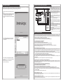
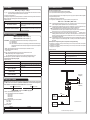
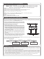
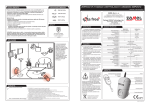
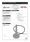
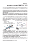
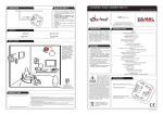
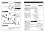
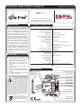
REMOTE GSM SWITCH GRM-10
MANUAL INSTRUCTION
ZAMEL Sp. z o.o.
ul. Zielona 27, 43-200 Pszczyna, Poland
Tel. +48 (32) 210 46 65, Fax +48 (32) 210 80 04
www.zamelcet.com, e-mail: [email protected]
DESCRIPTION
TECHNICAL PARAMETERS
The GRM-10 device is designed to
realise simple control and notice operations. The operations are carried out by
means of the GSM network. The controller has two independent outputs with a
maximum load capacity of 16 A / 250 V
AC. Two digital inputs allow for a link with
the alarm control panels. The RS485 interface in connection with the RXM-01
translator gives a possibility to control
EXTA FREE system receivers with the
help of a mobile phone and messages
that are defined by the user. The number
of operation modes and configuration
options make the GRM-10 a very useful
device for simple home automation and
industrial systems. The GRM-10 device
is made in a three-MOD casing and is
designed for mounting in switchboards
on a TH35 rail.
GRM-10
Nominal input rated voltage: 230 V AC 50 / 60 Hz
Input voltage tolerance: -15 ÷ +10 %
Nominal power consumption: 1,5 W
GSM frequency: 900/1800/1900 MHz
Operating range: restricted by the GSM network
Supply voltage optical signalling: LED diode (green)
GSM status signalling: LED diode (yellow)
Output number: 2
Output status signalling: 2 x LED diode
Output relays parameters: 2 x NO 16 A / 250 V AC AC1 4000 VA
Input number: 2
Input type: Digital - potential +4 V
RS485 MODBUS - A,B,C terminals; USB;
Interfaces:
PK1, PK2 push-buttons
RS485 transmission signalling: LED diode
Position on RS485 bus: only MASTER
Ambient temperature range: -10 ÷ +55 oC
Operating position: free
Casing mounting: TH35 rail
FEATURES
● Remote control of the electrical devices by means of commands (incoming phone connection, text message) sent from a mobile phone,
● Comfortable control of difficult access devices (air conditioning, heating, etc.),
● Two relay outputs with the load capacity of 16 A,
● Operation is optically signalled (power supply, relay status, GSM modem
status)
● Low power consumption, a possibility
of continuous operation.
The device is designed for singlephase installation and must be installed
in accordance with standards valid in a
particular country. The device should
CAUTION be connected according to the details
included in this operating manual.
Installation, connection and control should be carried out by a qualified electrician staff, who act in
accordance with the service manual and the device
functions. In case of casing dismantling an electric
shock may occur, and the guarantee is lost then.
Before installation make sure the connection cables
are not under voltage. The cruciform head screwdriver 3,5 mm should be used to instal the device.
Improper transport, storage, and use of the device
influence its wrong functioning. It is not advisable
to instal the device in the following cases: if any
device part is missing or the device is damaged or
deformed. In case of improper functioning of the device contact the producer.
The symbol means selective
collecting of electrical and electronic
equipment. It is forbidden to put the
used equipment together with other
waste.
Casing protection degree: IP20 (PN-EN 60529)
Protection class: II
Overvoltage category: II
Pollution degree: 2
Dimensions: 3-modular casing
Weight: 163 g
Reference standard: PN-EN 60950-1:2007; PN-EN 55024:2000;
PN-EN 61000-4-4
APPEARANCE
GSM range signalling
SIM card input
Power supply terminals
Input terminals
GSM antenna
Power supply signalling
Relay 1 (LEDP1)
status signalling
Relay 2 (LEDP2)
status signalling
RS-485 transmission
signalling
MICRO USB input
PK1, PK2 push-buttons
Output terminals
RS485 Interface
plik: inst_ext_pl_grm-10_gb | modyfikacja: 03.06.2013
SOFTWARE UPGRADE
CONNECTION AND INSTALLING DIAGRAM
CAUTION! The GRM-10 controller connection to a
single-phase installation must be done in accordance with standards valid in a particular country. The
device should be connected according to the details
included in this operating manual. Installation, connection and control should be carried out by a qualified electrician staff, who act in accordance with the
service manual and the device functions.
The GRM-10 user has the ability to upgrade the software using the Micro USB interface. It may be necessary in case of an upgrade
release by the producer. Information on the current software can be found on the product website:
http://www.zamelcet.com/pl,263,4537,sterownik_gsm_modulowy_2kanalowy_grm10.html.
The upgrade is carried out by the GRM-10 application on
the PC:
1.After switching off the power supply voltage connect the
GRM-10 device to the PC by means of a USB, Micro B /
USB cable and pressing the PK2 push-button.
2.Start the GRM-10 application and select the UPGRADE
window.
Optional element
to control
EXTA FREE
receivers
1.Disconnect power supply by the phase fuse, the circuit-breaker or the switch-disconnector combined to
the proper circuit.
2.Check if there is no voltage on connection cables by
means of a special measure equipment.
3.Connect the GRM-10 device to 230 V AC power supply.
4.Connect the remaining cables with the appropriate
terminals of the GRM-10 controller according to the
installing diagram.
5.Insert into the SIM input the active SIM card with
funds available. Before installing switch off the
PIN code or adjust it choosing 1111. It is recommended to switch off the voice mail.
6.Carry out a proper device configuration (see DEVICE
CONFIGURATION).
7.Switch on the power supply from the mains. Wait until
the proper GSM network log in. Check the correctness
of the operation.
DEVICE CONFIGURATION
3.Select “Software Upgrade” and then select the latest
version of the GRM-10 software (the *. ZMS) from a
specific location.
4.If the software is successfully updated the application
will show a comment: “The software has been updated”.
5.Press “OK.”
6.Disconnect the USB Micro B / USB A cable.
7.Switch on the power supply.
GRM-10 has a default factory settings. Before use, carefully read the manual instruction and make a proper device configuration. In order
to freely manage the configuration settings, the GRM-10 device makes the local and remote configuration possible. The remote configuration allows to manage the settings of the already working GRM-10 device without a physical access to it (for example, to a device that is
installed in the building). The configuration can be done as follows:
a) by means of a mobile phone via text massage (local and remote configuration),
b) by means of the PC application via the Micro USB interface (only the local configuration).
Local configuration by means of a mobile phone
1.Press the PK2 push-button on the front panel.
2.Switch on the power supply and keep the PK2 push-button pressed.
3.Hold the PK2 push-button as long as the LED red diodes LEDP1 and LEDP2 start flashing.
4.Wait until the GRM-10 device logs into the GSM network (LED yellow diode GSM flashes).
5.Adjust the configuration parameters by sending appropriate text messages (see CONFIGURATION COMMANDS).
6.Switch off the power supply from the mains.
Remote configuration by means of a mobile phone
The remote configuration is available only for these telephone numbers that have been added to the so called administrative numbers’ list
by means of the configuration command ADMIN (see CONFIGURATION COMMANDS) during the local configuration (by means of a text
message or a PC application). The remote configuration is possible during a usual device operation if it is “logged in” to the GSM network.
1.Send a text message with a CONFIG MODE content from a telephone number included on the ADMIN list.
2.By receiving the above text message, the GRM-10 device will send back a reply “CONFIG MODE OK’ and will enter the configuration
mode, which is indicated by flashing red LED diodes LEDP1 and LEDP2.
3.Carry out the device configuration in accordance with the CONFIGURATION COMMANDS.
4.Send a TEXT MESSAGE with the CONFIG MODE END content to leave the remote configuration mode.
5.By receiving the above text message, the GRM-10 device will send back a reply “CONFIG MODE END -OK’ and will enter a usual
operation mode
When entering / leaving the remote configuration mode, the outputs’ status remains unchanged.
Configuration by means of the PC application via an MIC RO USB interface
NOTE: Every time before making any changes in the configuration settings by means of the PC application, first read the current configuration of the GRM-10 device. It is necessary not to overwrite or lose the configuration settings implicated by the telephone text message.
1.Start the GRM-10 application on PC.
2.Switch off the power supply to connect the MICRO USB to the GRM-10 device.
3.Wait until the GRM-10 device appears in the operating system to install properly.
4.READ CURRENT GRM-10 DEVICE CONFIGURATION.
5.Carry out / change the configuration adjustments by means of the PC application.
6.In order to save the current configuration of the GRM-10 device, press the “ZAPISZ DO URZĄDZENIA” push-button.
7.Press shortly the PK1 push-button on the front panel of the GRM-10 device (LED yellow diode RS485 switches on for a moment).
8.If the configuration is correct, the application sends back a message ‘CONFIGURATION OK.’ Otherwise the message ‘CONFIGURATION ERROR’ displays.
9.Disconnect the MICRO USB cable from the GRM-10 device.
Saving the configuration to *. zml file
The current configuration can be saved to a ‘*.zml’ file. In order to do it, by means of the application press the “ZAPISZ DO PLIKU’ pushbutton and select the proper file place to save it.
Reading the configuration from the *. zml file
The current configuration can be read from the ‘*.zml’ file. In order to do it, by means of the application press the “WCZYTAJ Z PLIKU”
push-button, next choose the correct file place to read it.
CONFIG COMMAND
DEVICE CONTROL
Type of control
Possible control types
Remarks
MANUAL
● Bistable ON/OFF
By means of PK1 / PK2 push buttons on ● Time TIME
the front panel
● Gate GATE
● Times for TIME and GATE modes are adjusted during configuration.
CLIP
By calling to the device
(specified number of signals)
● Bistable ON/OFF
● Time TIME
● Gate GATE
● Times for TIME and GATE modes are adjusted during configuration.
● The number of signals specified during configuration (in
ON / OFF and TIME modes the user must disconnect after
certain number of signals, in the GATE mode the disconnection is automatical.
TEXT MESSAGE
By sending a specified message with a
control command to the device
● Bistable ON/OFF
● Time TIME
● Gate GATE
● EXTA FREE control
● Times for the TIME and GATE modes are adjusted during
configuration with a possibility of changing the text in the
control text message.
*ON / OFF bistable mode - change of the CH1 or CH2 output status to the opposite.
*TIME time mode - change of the CH1 or CH2 output status to the opposite and appropriately through time t1 for CH1 output and time
t2 for CH2 output.
*GATE gate mode - change of the CH1 and / or CH2 into times defined for the gate mode.
*EXTA FREE control - control of EXTA FREE system wireless receivers by means of RXM-01 device RXM-01 connected with the GRM10 device.
CONFIGURATION COMMANDS
Command
Description
CONFIG <+48tel_1> <+48tel_n> PASS <password from 5 to 8 signs> ACK <REL1,REL2, REL12>
The maximum of numbers available n = 6
PASS Keyword - it specifies the password added to the text message during control. The password is added at the beginning of the
message. No parameter means a free access for any number during text message control.
ACK
Keyword - it specifies whether the GRM-10 device must send a confirming text message every time after a specified command
is realised:
REL1 confirmation only for CH1 channel
REL2 confirmation only for CH2 channel
REL12 confirmation for channels CH1 and CH2
<>
No parameter means no confirmation for channels CH1 and CH2
Examples of commands:
Command
Description
CONFIG +48602360938 +48600915257
Numbers +48602360938, +48600915257 globally released to
control CLIP, no password for text message control, no confirmations for OUT1 and OUT2 outputs.
CONFIG +48602360938 +48600915257 ACK REL1
Numbers +48602360938, +48600915257 globally released to
control CLIP, no password for text message control, confirmations
only for OUT1 output.
CONFIG +48602360938 +48600915257 ACK REL2
Numbers +48602360938, +48600915257 globally released to
control CLIP, no password for text message control, confirmations
only for OUT2 output.
CONFIG +48602360938 +48600915257 ACK REL12
Numbers +48602360938, +48600915257 globally released to
control CLIP, no password for text message control, confirmations
for OUT1 and OUT2 outputs.
Numbers +48602360938, +48600915257 globally released to
CONFIG +48602360938 +48600915257 PASS ZAMEL ACK REL1 control CLIP, ZAMEL password for text message control, confirmations only for OUT1 output.
CONFIG
● Configuration of telephone numbers authorized to control the CLIP.
● Configuration of the optional password for controlling text messages.
● Configuration of confirmation.
CONFIG MODE
● Adjusting the device for the remote configuration mode.
CONFIG MODE END
● Deleting the remote configuration mode.
ADD NUM
● Entering additional phone numbers to the list of numbers authorised to control the CLIP. By means of
one commend maximum six numbers can be added every time. Applies to local and remote configuration
DEL NUM
● Deleting a number (s) from the list of telephone numbers authorized to control the CLIP. Every time by
means of one command up to six numbers may be deleted. It refers to local and remote configuration.
ADMIN
● Configuration of telephone numbers authorized to a remote configuration.
INFO
● Configuration of telephone numbers the text messages will be sent to (it refers to the outputs’ status
and occurrences on IN1, IN2 inputs).
tel_1...tel_n successively entered phone numbers preceded by +48.
The maximum of numbers available n = 6.
RELAY1
● Operation mode configuration for CH1 output.
● Operation mode configuration of CH1 output after power supply voltage is switched off.
Examples of commands:
RELAY2
● Operation mode configuration for CH2 output.
● Operation mode configuration of CH2 output after power supply voltage is switched off.
MODBUSCONFIG
● Configuration of RS485 transmission parameters for MODBUS protocol.
GATE
● Gate mode configuration.
TASK IN1
● IN1 input configuration.
TASK IN2
● IN2 input configuration.
EF
● Control command configuration for EXTA FREE system.
EF RESET
● Deleting the control command table for EXTA FREE system.
RESET CONFIG
● Restore the default settings (it does not refer to EXTA FREE commands).
NOTE: If there is a need to add more authorised numbers to control the CLIP (including control in the gate mode) it can be
done by means of the PC application (telephone section) or the ADD NUM command in configuration mode. It is possible to
enter up to 500 numbers. In order to delete the selected telephone number, use the PC application or the DEL NUM command
in configuration mode.
ADD NUM COMMAND
The command adds a telephone number / numbers to the authorised list of numbers used to control CLIP (including the control in the
gate mode). 6 telephone numbers maximally can be added by one command at each time. The command refers to the local and remote
configuration.
ADD NUM <+48tel_1> <+48tel_2>,...,<+48tel_n>
Command
Description
ADD NUM +48602360938
Number +48602360938 is added to the authorised list of numbers
used to control by means of CLIP calling signals.
ADD NUM+48603360928 +48600915257 +48600500800
Numbers +48603360928 +48600915257 +48600500800 are added to the authorised list of numbers used to control by means of
CLIP calling signals.
DEL NUM COMMAND
The command deletes a telephone number / numbers from the authorised list of numbers used to control CLIP (including the control in
the gate mode). 6 telephone numbers maximally can be deleted by one command at each time. The command refers to the local and
remote configuration.
DEL NUM <+48tel_1> <+48tel_2>,...,<+48tel_n>
CONFIGURATION MODE COMMAND
The command makes the GRM-10 device enters from the normal operation mode into the remote configuration mode. The active command is only for the numbers included in the ADMIN list (by means of ADMIN command or the PC application). The enter into the configuration mode is indicated by a flashing LED diodes LEDP1 and LEDP2.
CONFIGURATION MODE END COMMAND
The command allows the the GRM-10 device to go out from the configuration mode to normal operation. The active command is only
for the numbers included in the ADMIN list (by means of ADMIN command or the PC application). The command is inactive during
local configuration.
tel_1...tel_n successively entered phone numbers preceded by +48.
The maximum of numbers available n = 6.
Examples of commands:
Command
Description
DEL NUM +48602360938
Number +48602360938 is deleted from the authorised list of numbers used to control by means of CLIP calling signals.
DEL NUM+48603360928 +48600915257 +48600500800
Numbers +48603360928 +48600915257 +48600500800 are deleted from the authorised list of numbers used to control by means
of CLIP calling signals.
INFO COMMAND
GATE COMMAND (GATE MODE)
INFO <+48tel_1> <+48tel_2>,...,<+48tel_n>
tel_1...tel_n successively entered phone numbers preceded by +48. The text messages will be sent to these numbers. The confirmations refer to the changed output status and occurences on IN1, IN2 inputs.
The maximum of numbers available n = 6.
The confirming text messages are sent only if the ACK parameter is set in the CONFIG command. Sending the INFO command with new
telephone numbers results in deleting the previous numbers and writing the new ones.
Examples of commands:
Command
INFO +48602360938 +48600915257
INFO +48602360938 +48600915257 +48600500800
Description
Text messages will be sent to the following numbers +48602360938,
+48600915257 confirming the realization of a specified control command or
occurences on inputs.
Text messages will be sent to the following numbers +48602360938,
+48600915257, +48600500800 confirming the realization of a specified control
command or occurences on inputs.
RELAY1 / RELAY 2 COMMAND
<ON/OFF/MEM>
RELAY1 <ON/OFF/MEM> <mode> <t1> RING <y>
RELAY2 <ON/OFF/MEM> <mode> <t2> RING <y>
The parameter defines the output status OUT1/OUT2 after switching on power supply from the mains:
ON Output switched on.
OFF Output switched off.
MEM GRM-10 remembers the output status - when the power supply is switched off and then switched on again,
the output has the same status as it was before the power supply switch off. The parameter is not adjusted for
the TIME mode..
<mode> A parameter that defines the operating mode of OUT1/OUT2 outputs - it is default for CLIP control.
ONOFF Bistable mode (Switch on / switch off).
TIME Time mode.
<t1>/<t2> A parameter that defines default times [s] for the time mode - possible value from 1 to 3600
RINGA keyword defining the number of ring signals to control CLIP.
<y> A parameter defining the number of rings to control CLIP. The parameter is adjusted in the range of 2 to 12.
If the RING keyword and <y> parameter is not adjusted, the control is carried out only by sending text messages.
OUT1/OUT2 outputs are independently configurable.
Examples of commands:
Command
RELAY1 ON ONOFF RING 3
RELAY1 MEM ONOFF RING 2
RELAY1 OFF TIME 60 RING 4
RELAY2 OFF ONOFF
RELAY2 ON TIME 10 RING 2
Description
OUT1 output is switched on, bistable mode, adjustment after three rings.
OUT1 output in the status before power supply switch off, bistable mode, activation after two rings
OUT1 output is switched off, time mode, time 60 seconds, adjustment after
4 rings
OUT2 output is switched off, bistable mode, control only by means of text message
OUT2 output is switched on, time mode, time 10 seconds, adjustment after
2 rings
In the gate mode the settings are as follow:
OUT1 - it cooperates with the existing gate controller that controls the gateway.
OUT2 - it cooperates with the electric latch opening the entry gate to the possession.
The number of telephones authorized to control in the gate mode by means of a ring (CLIP) are adjusted in the CONFIG configuration
mode (up to 6 numbers) or by means of:
● the ADD NUM command in the configuration mode,
● the PC application in the Telephones section / CLIP (up to 500 numbers) in the configuration mode.
GATE <TIME 1> <TIME2> RING <y> AUTO <TIME3>
<TIME 1> A parameter that defines the default time [s] of the OUT1 output - configurable in the range of 0 to 10. OUT1 task is to generate
a pulse to the gateway controller. If this parameter is set to “0”, then OUT1 output is inactive.
<TIME 2> A parameter that defines the default time [s] of the OUT2 output - configurable from 0 to 360. The OUT2 output task is to provide voltage supply to the electric latch. If this parameter is set to “0”, then the OUT2 output is inactive.
RINGA keyword that defines the number of rings to control outputs in the gate mode by means of a CLIP.
<y> A parameter that defines the number of rings to control outputs in the gate mode by means of a CLIP. This parameter is configured in the range of 2 to 6. If it is not set, the control is carried out only by means of text messages.
AUTO A keyword to configure the AUTO mode. In the AUTO mode, after <TIME 3> finishes a gate controller’s pulse is automatically generated for a defined <TIME1> time. This impulse is to automatically close the door. If the AUTO mode is activated, the gate remains open till the GATE command is activated, till the next “CLIP’a”, till the next pulse in IN1 input or till
another pressing of the PK1 push-button.
<TIME3> A parameter that defines the time [s] during which the gate remains open. The time is measured after <TIME1> finishes. It is
configured in the range from 1 to 600. While adjusting <TIME3> it is necessary to take into consideration the time taken to
open the gate..
IN1/IN2 inputs are not configurated in the gate mode. The inputs have the following default settings:
● The appearance of a short pulse in the IN1 input results in switching on the OUT1 output for the time <TIME1> that is adjusted
during the gate mode configuration.
● The appearance of a short pulse in the IN2 input results in switching on the OUT2 output for the time <TIME2> that is adjusted
during the gate mode configuration..
Examples of commands:
Command
Description
GATE 2 15 RING 2
time1 = 2 s, time2 = 15 s, setting the CLIP after 2 rings
time1 = 2 s, time2 = 10 s, setting the CLIP after 2 rings, automatically generating pulse to close the gate after time3 = 350 s
GATE 2 10 RING 2 AUTO 350
GATE 2 100
time1 = 2 s, time2 = 100 s, control only by means of tex messages
GATE 0 60
Pulse generation only to open the doorway (latch operation time = 60 s)
GATE 2 0
Pulse generation only to open the gate (pulse time = 2 s)
Manual control
of the gateway
MODBUSCONFIG COMMAND
Default MODBUS protocol configuration in GRM-10 device allows for a direct connection with EXTA FREE translator / RS-485 RXM-01
type. GRM-10 device in such a connection is only a MASTER on the MODBUS bus - it receives control text messages and by
means of RS-485 bus it sends appropriate commands to the RXM-01 device. A default configuration:
Protocol: MODBUS RTU 8 bits of data
Transmission rate: 9600 kbps
Manual control
of the doorway
Parity: Parity bit + stop bit
Address on the bus: 0x01
MODBUSCONFIG <address> <rate> PARITY <parity options>
<address> A parameter defining address on the bus: 1...247.
<rate> A parameter defining transmission rate on the RS-485 bus:
2400 - 2400 kbps,
4800 - 4800 kbps,
9600 - 9600 kbps,
19200 - 19200 kbps
PARITYA keyword defining parity options. Selection possibilities:
NO – no parity
ODD – odd test
EVEN – parity test.
Examples of commands:
Command
MODBUSCONFIG 1 9600 PARITY EVEN
MODBUSCONFIG 1 2400 PARITY ODD
Description
Address 0x01, transmission rate 9600kbps, parity test
Address 0x01, transmission rate 2400kbps, odd test
<time1>
GATE
CONTROLLER
<time3>*
<time2>
ELECTRIC LATCH
OF THE DOORWAY
The GRM-10 connection diagram in the gate mode
* if the parameter AUTO is set
TASK IN 1 / TASK IN 2 COMMAND
EF COMMAND
TASK IN1 <LO/HI> RELAY1 <ON/OFF> or TASK IN2 <LO/HI> RELAY2 <ON/OFF>
TASK IN1 <LO/HI> RELAY1 TIME <t1> or TASK IN2 <LO/HI> RELAY2 TIME <t2>
TASK IN1 <LO/HI> NONE or TASK IN2 <LO/HI> NONE
KEYWORDS
TASKI IN1/TASK IN2 – defines the output the configuration refers to.
RELAY1/RELAY2 – defines the output that must be activated after a given status occurance in the input
TIME – defines that after an occurrence of the <LO/HI> status in IN1 / IN2 input, the OUT1/OUT2 output changes its status for a time
limited by <t1> <t2> parameters.
NONE – defines that after an occurrence of the <LO/HI> status in IN1 / IN2 input, the GRM-10 device avoids the status (it does not respond).
PARAMETERS
<LO/HI> A parameter for the keyword TASK IN1/TASK IN2 defining the level of the input IN1/IN2 that activates a specific output occurrence. The normal status of the IN1/IN2 inputs is the high state HI. The low status is achieved by linking the selected input
to terminal C.
<ON/OFF> A parameter for the RELAY1/RELAY2 keyword - it defines the output status:
ON - the output is on.
OFF - the output is off.
<t1> Time [s] of the OUT1 / OUT2 output after a defined status occurred in IN1 input. This parameter is configured in the range of
1 to 3600.
<t2> Time [s] of the OUT1 / OUT2 output after a defined status occurred in IN1 input. This parameter is configured in the range of
1 to 3600.
CLIP or TEXT MESSAGE control have a higher priority than inputs. It means that if a specific status occurs in IN1/IN2 inputs, the OUT1
/OUT2 output is switched on permanently or only for <t1>/<t2> time. It can be switched off by means of a CLIP or a TEXT MESSAGE
any time.
In case of MEM parameter adjustment (in RELAY1 / RELAY2 configuration commands) for a selected output, the adjustment remembered
for inputs in the time mode is the status before activation of the <t1>/<t2>.
TASK IN1 <LO/HI> NONE MESSAGE <text message content up to 30 signs>
TASK IN2 <LO/HI> NONE MESSAGE <text message content up to 30 signs>
MESSAGEA keyword - it defines the text message content to be sent by the GRM-10 device to its receivers. Their telephone numbers
are configured in the INFO command. The text message can include up to 30 signs. The occurrence of a specific status <LO/
HI> in the input results in sending a text message.
TASK INx <LO/HI> RELAYx <ON/OFF/TIME> <tx> MESSAGE <text message content up to 30 signs>
The command makes the connection between the specific status occurrence (LO/HI) in the IN1/IN2 input with an appropriate activation
of the OUT1 / OUT2 output and sending a text message (MESSAGE) with a defined content..
X number of an input / output
1 input /output IN1/OUT1
2 input /output IN2/OUT2
<tx> f the output must be active for a period of time (TIME), then the parameter defines time for the time mode. This parameter is configured in the range of 1 to 3600.
Examples of commands:
Command
TASK IN1 LO RELAY1 ON
TASK IN1 HI RELAY2 OFF
TASK IN2 LO RELAY1 TIME 30
TASK IN1 HI RELAY2 TIME 10
TASK IN1 LO NONE
TASK IN2 HI NONE
TASK IN1 LO NONE MESSAGE
WODA W POMIESZCZENIU
TASK IN1 HI NONE MESSAGE
WODA WYPOMPOWANA
TASK IN1 LO RELAY1 ON MESSAGE
STAN NISKI NA IN1
TASK IN2 LO RELAY2 TIME 60 MESSAGE
ODLICZANIE CZASU
Description
After LO status appears in IN1 input, the OUT1 output switches on.
After HI status appears in IN2 input, the OUT2 output switches off.
After LO status appears in IN2 input, the OUT1 output status changes for
30 sec.
After HI status appears in IN1 input, the OUT2 output status changes for 10
sec.
After LO status appears in IN1 input, no GRM-10 reaction.
After HI status appears in IN2 input, no GRM-10 reaction.
After LO status appears in IN1 input, the „WODA W POMIESZCZENIU” message is sent.
After HI status appears in IN1 input, only the „WODA WYPOMPOWANA”
message is sent.
After LO status appears in IN1 input, the OUT1 output switches on and a text
message „STAN NISKI NA IN1” is sent.
After LO status appears in IN2 input, the OUT2 output changes for time t=60
sec. + a text message „ODLICZANIE CZASU” is sent.
WARRANTY CARD
There is 24 months guarantee on the product
Salesman stamp and signature, date of sale
1. ZAMEL Sp. z o.o. assures 24 months guarantee for the product.
2. The manufacturer’s guarantee does not cover any of the following actions:
a) mechanical damage during transport, loading / unloading or under other circumstances,
b) damage caused by incorrect product mounting or misuse,
c) damage caused by unauthorised modifications made by the PURCHASER or any third parties to the product or any other devices
needed for the product functioning,
d) damage caused by Act of God or any other incidents independent of the manufacturer - ZAMEL Sp z o.o.
e) power source (batteries) in the device during sale (if any).
3. The PURCHASER shall lay any claims in writing to the dealer or ZAMEL Sp. z o.o.
4. ZAMEL Sp. z o.o. is liable for processing any claim according to current Polish legislation.
5. ZAMEL Sp. z o.o. shall process the claim at its own discretion: product repair, replacement or money return.
6. The manufacturer’s guarantee is valid in the Republic of Poland.
7. The PURCHASER’s statutory rights in any applicable legislation whether against the retailer arising from the purchase contract or
otherwise are not affected by this warranty.
he command allows to configure text messages used to control EXTA FREE system wireless receivers and selected LED lighting fittings
and controllers of intelligent lighting Ledix series system. The control is possible only when the GRM-10 device is connected with the
RXM-01 translator (www.extafree.pl) by means of RS-485 bus.
EF <address> <K1..Kn> <control text message content>
<address>This parameter defines the RXM-01 translator address on MODBUS bus that the specific control command refers to. This
parameter is configured in the range of 1 to 247.
<K1...Kn> The parameter defines the the number of push-buttons used to control EXTA FREE system receivers (possible numbers from
1 to 127). In one EF command up to 15 numbers of push-buttons can be configured. The push-buttons refer to a single control
text message, for example in order to adjust several EXTA FREE system receivers by means of one text message.
<control text message content> The control command is adjusted by a user, the maximum number of signs is 32.
The user can define 127 independent control commands. The commands can not be repeated - if the command including a given content
already exists, the GRM-10 device will display ERROR as a response to this configuration text message. A similar message is given by
the PC application. The control commands generated by the EF command are grouped in a table. Commands generated as text messages are placed at the end of the table and from a PC at the beginning. It should be helpful for the user to add new commands by means
of a telephone. The maximum number of EF commands that can be configured is 127.
The EF commands table can be completely deleted by sending a EF RESET command in the configuration mode.
The user can configure the EF command in such a way as to adjust simultaneously several (up to 15) EXTA FREE / LEDIX system receivers, which are located within RXM-01 range. It is very important in creation the so called scenes or, for example, in the control of central
roller blind drives. The next push-buttons codes are sent in a ”one by one” sequence with an interval of 1 second.
The cooperation of GRM-10 device with RXM-01 device is fully described in the EXTA FREE CONTROL section by means of GSM.
Examples of commands:
Command
EF 1 K1 OSWIETLENIE ON
EF 1 K2 OSWIETLENIE OFF
EF 2 K3 SCHODY ON
EF 2 K4 SCHODY OFF
EF 1 K3 ROLETY GORA
EF 1 K4 ROLETY DOL
EF 1 K1 K3 ALL ON
(example of a stage)
Description
A text message with the content ‘OSWIETLENIE ON’ – results in sending a code by RXM-01 with the
0x0,1 address to press a 0x0,1 push-button. The result is that the receiver with this code is switched on.
A text message with the content ‘OSWIETLENIE OFF’ – results in sending a code by RXM-01 with the
0x0,1 address to press a 0x0,2 push-button. The result is that the receiver with this code is switched off.
A text message with the content ‘SCHODY ON’ – results in sending a code by RXM-01 with the 0x0,2
address to press a 0x0,3 push-button. The result is that the receiver with this code is switched on.
A text message with the content ‘SCHODY OFF’ – results in sending a code by RXM-01 with the 0x0,2
address to press a 0x0,4 push-button. The result is that the receiver with this code is switched on.
A text message with the content ‘ROLETY GORA’ – results in sending a code by RXM-01 with the 0x0,1
address to press a 0x0,3 push-button. It results in opening the roller blind connected to SRP-02 with
this code.
A text message with the content ‘ROLETY DÓŁ’ – results in sending a code by RXM-01 with the 0x0,1
address to press a 0x0,4 push-button. It results in closing the roller blind connected to SRP-02 with
this code.
A text message with the content ‘ALL ON’ – results in switching on the light and opening the roller
blinds - it is equivalent to sending codes by RXM-01 with the 0x0,1 address to receivers to press 0x0,1
and 0x0,3 push-buttons.
OUTPUT CONTROL COMMANDS
Command
RELAY1 ON
RELAY1 OFF
RELAY2 ON
RELAY2 OFF
RELAY1 TIME
RELAY2 TIME
Description
Przykład
Switch on OUT1 output
Switch off OUT1 output
Switch on OUT2 output
Switch off OUT2 output
Change of OUT1 output status for time t1[s] adjusted during configuration
Change of OUT2 output status for time t2[s] adjusted during configuration
Change of OUT1 output status for time <t> given in the control command. <t> parameter is adRELAY1 TIME <t>
RELAY1 TIME 60
justed in the range of 1 .... 3600.
Change of OUT2 output status for time <t> given in the control command. <t> parameter is adRELAY2 TIME <t>
RELAY2 TIME 10
justed in the range of 1 .... 3600.
Output control in the gate mode. Switching on the OUT1 output for the default time <TIME1>
and the OUT2 output for the default time <TIME2>. If the AUTO parameter is adjusted for the
GATE
gate mode, the pulse to close the gate is automatically generated after time <TIME3> is finished.
Times <TIME1>, <TIME2> and <TIME3> are adjusted during the gate mode configuration.
Output control in the gate mode. Switching on the OUT1 output for time <t1> and the OUT2 output for time <t2>. The <t1> parameter is adjusted in the range of 0 .... 10 and the <t2> parameter
GATE <t1> <t2> in the range of 0 .... 360. If the AUTO parameter is adjusted for the gate mode, the pulse to close
GATE 2 120
the gate is automatically generated after time <TIME3> is finished. Time <TIME3> is adjusted
during the gate mode configuration.
STATUS
Checking the output/input status (section: GRM-10 DEVICE REPLY TO STATUS COMMAND)
CAUTION: If the PASS parameter (password to a text message) was adjusted during configuration in the CONFIG command,
then the adjusted password must be typed during the text message control at the beginning.
Example: (adjusted password „Zamel”):
Zamel RELAY1 ON; Zamel RELAY2 OFF; Zamel RELAY1 TIME 10; Zamel GATE; Zamel GATE 2 20
GRM-10 DEVICE REPLY TO STATUS COMMAND
A full GRM-10 device reply to STATUS command:
RELAY1 <ON/OFF - current OUT1 output status> TIME <Time left to measure for OUT1 output>
RELAY2 <ON/OFF - current OUT2 output status> TIME <Time left to measure for OUT2 output>
IN1 <LO/HI - current IN1 input status> IN2 <LO/HI - current IN2 input status>
Example:
RELAY1 ON TIME 30 RELAY2 OFF TIME 100 IN1 LO IN2 HI
If times for OUT1/OUT2 outputs are currently not measured, the reply to the STATUS command is:
RELAY1 <ON/OFF - current OUT1 status> RELAY2 <ON/OFF - current OUT2 status>
IN1 <LO/HI - current IN1 status> IN2 <LO/HI - current IN2 status>
or
RELAY1 <ON/OFF - current OUT1 status> TIME <0> RELAY2 <ON/OFF - current OUT2 status> TIME <0>
IN1 <LO/HI - current IN1 status> IN2 <LO/HI - current IN2 status>
Example:
RELAY 1 ON RELAY 2 OFF IN1LO IN2HI
RELAY 1 ON TIME 0 RELAY 2 OFF TIME 0 IN1LO IN2HI
CONTROL OF EXTA FREE SYSEM RECEIVERS
The GRM-10 device, by receiving certain commands (text messages), can control the wireless EXTA FREE system receivers. It is necessary to connect the GRM-10 device with RXM-01 translator using the RS-485 interface. The GRM-10 device has such a default setting
that allows for a direct cooperation with RXM-01. If the transmission parameters change is necessary (standard, transmission rate, parity)
between GRM-10 and RXM-01 use the MODBUSCONFIG command.
CAUTION: The transmission line between the GRM-10 device and the RXM01 device is a two-wire shielded twisted-pair cable (it is recommended to earth
in a single point the shield line). The resistors (terminators) of 120 Ohm should
be placed at the beginning and at the end of the line.
he following points should also be carried out:
1.Connect the RXM-01 device to a PC. An appropriate “adapter” RS232 RS485 or USB - 485 (depending on the computers’ output) should be used.
2.Using the PC application that is dedicated to configure the GRM-10 device,
particular control commands and responding number of push-buttons shall
be defined in the EXTA fREE section. For each command, specify The RXM01 address for the MODBUS bus should be defined. The default address is
0x01. The address is important for a larger number of RXM-01 operating
independently on a single object.
3.Following the description of the PC, add (programme) particular push-buttons sent by the RXM-01 device to appropriate EXTA FREE system receivers.
4.After programming the receivers, use the PC application to check their appropriateness.
5.Adjust the GRM-10 device into a normal operation mode and check the
operation by sending defined control commands to the GRM-10 device (the
proper communication between RXM-01 and GRM-10 after sending a control command is indicated by the LED diode RS485, it switches on).
If in the EXTA FREE control command several push-buttons are defined, the codes are sent to RXM-01 device with a defined address in
a sequence one after another and with an interval of 1 sec.
Example: EF K1 K2 K3 SALON OFF
Sending
the K1 code
1sec.
Sending
the K2 code
The receiver added to K1
is activated
1sec.
Sending
the K3 code
The receiver added to K2
is activated
1sec.
The receiver added to K3
is activated
REMARKS
● Due to the queuing (prioritisation) of text messages in the GSM network, some delays related to sending the control command
and its realisation are possible (for example the adjustment of the GRM-10 outputs or EXTA FREE receivers). The delays can
be from several to tens o seconds.
● Due to the representation of the text message content, the configuration and control of the GRM-10 device is not possible by
means of ”SMS gateways” that are provided by the GSM operators.
● In case of operators using other resources of the GSM network, it is not possible to choose the operator manually. The logging
procedure is automatical - the operator with the strongest signal is chosen. Successful login of the GRM-10 device to the GSM
network is indicated by a flashing LED GSM STATUS diode with a frequency of 1/s. Make sure that the device is mounted in
areas with the GSM network reception. Operation on the reception border can have a negative influence on a proper operation
of the GRM-10 device and other devices in cooperation.
● It is important to switch off the PIN code or adjust the code to 1111 before installing the SIM card in the GRM-10 device.
● It is recommended to switch of the VOICEMAIL service on the card installed in the GRM-10 DEVICE.