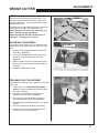
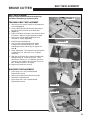
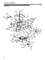
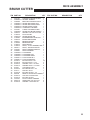
1
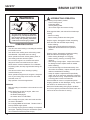
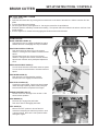
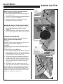
BRC-24 HYDRO
24” LITTLE WONDER BRUSH CUTTER
5024-22-01
OPERATOR / PARTS MANUAL
Rev A. 10-2011
Original Language Instructions
MAN C100571
LITTLE WONDER
®
CALIFORNIA
WARNING
Proposition 65 Warning
Diesel engine exhaust and some
of its constituents are known to the
State of California to cause cancer,
birth defects and other reproductive
harm.
The engine exhaust from this product
contains chemicals known to the State
of California to cause cancer, birth
defects or other reproductive harm.
CALIFORNIA
Proposition 65 Warning
Battery posts, terminals, wiring
insulation, and related accessories
contain lead and lead compounds,
chemicals known to the State of
California to cause cancer and birth
defects or other reproductive harm.
WASH HANDS AFTER HANDLING.
BRUSH CUTTER
IMPORTANT MESSAGE
Thank you for purchasing this Schiller Grounds Care, Inc. product. You have purchased a world class product, one of the best designed and
built anywhere.
This machine comes with an Operation and Safety Manual, Parts and Service Manual, and Engine Manual. The useful life and good service you
receive from this machine depends to a large extent on how well you read and understand these manuals. Treat your machine properly, lubricate
and adjust it as instructed, and it will give you many years of reliable service.
Your safe use of this Schiller Grounds Care, Inc. product is one of our prime design objectives. Many safety features are built in, but we also rely
on your good sense and care to achieve accident-free operation. For best protection, study the manuals thoroughly. Learn the proper operation
of all controls. Observe all safety precautions. Follow all instructions and warnings completely. Do not remove or defeat any safety features.
Make sure those who operate this machine are as well informed and careful in its use as you are.
See a Schiller Grounds Care, Inc. dealer for any service or parts needed. Schiller Grounds Care, Inc. service ensures that you continue to receive
the best results possible from Schiller Grounds Care, Inc. products. You can trust Schiller Grounds Care, Inc. replacement parts because they
are manufactured with the same high precision and quality as the original parts.
Schiller Grounds Care, Inc. designs and builds its equipment to serve many years in a safe and productive manner. For longest life, use this
machine only as directed in the manuals, keep it in good repair and follow safety warnings and instructions. You’ll always be glad you did.
Schiller Grounds Care, Inc.
1028 Street Road
Southampton, PA 18966-4217
PHONE 877-596-6337 • FAX 215-357-8045
TABLE OF CONTENTS
FIGURES
PAGE
SAFETY..........................................................................................................................................................4-8
LABELS........................................................................................................................................................9-10
SET-UP INSTRUCTIONS / CONTROLS......................................................................................................... 11
OPERATION ..............................................................................................................................................12-13
MAINTENANCE.........................................................................................................................................14-16
ADJUSTMENTS ........................................................................................................................................17-20
BELT REPLACEMENT.................................................................................................................................... 21
STORAGE....................................................................................................................................................... 22
TROUBLESHOOTING...............................................................................................................................23-24
SPECIFICATIONS / WARRANTY................................................................................................................... 25
PARTS SECTION............................................................................................................................................ 27
DRIVE ASSEMBLY............................................... FIGURE 1.................................................................... 28, 29
HANDLE ASSEMBLY........................................... FIGURE 2.................................................................... 30, 31
DECK ASSEMBLY................................................ FIGURE 3.................................................................... 32, 33
This Operator / Parts Manual is part of the machine. Suppliers of both new and
second-hand machines must make sure that this manual is provided with the
machine.
10-2011
3
SAFETY
BRUSH CUTTER
NOTICE !!!
Unauthorized modifications may present extreme
safety hazards to operators and bystanders and
could also result in product damage.
Schiller Grounds Care, Inc. strongly warns against,
rejects and disclaims any modifications, add-on
accessories or product alterations that are not
designed, developed, tested and approved by Schiller
Grounds Care, Inc. Engineering Department. Any
Schiller Grounds Care, Inc. product that is altered,
modified or changed in any manner not specifically
authorized after original manufacture-including the
addition of “after-market” accessories or component
parts not specifically approved by Schiller Grounds
Care, Inc. will result in the Schiller Grounds Care,
Inc. Warranty being voided.
Any and all liability for personal injury and/or
property damage caused by any unauthorized
modifications, add-on accessories or products not
approved by Schiller Grounds Care, Inc. will be
considered the responsibility of the individual(s) or
company designing and/or making such changes.
Schiller Grounds Care, Inc. will vigorously pursue
full indemnification and costs from any party
responsible for such unauthorized post-manufacture
modifications and/or accessories should personal
injury and/or property damage result.
This symbol means:
ATTENTION!
BECOME ALERT!
Your safety and the safety of others is involved.
Signal word definitions:
The signal words below are used to identify levels
of hazard seriousness. These words appear in this
manual and on the safety labels attached to Schiller
Grounds Care, Inc. machines. For your safety and
the safety of others, read and follow the information
given with these signal words and/or the symbol
shown above.
DANGER indicates an imminently hazardous
situation which, if not avoided, WILL result in death
or serious injury.
WARNING indicates a potentially hazardous
situation which, if not avoided, COULD result in
death or serious injury.
CAUTION indicates a potentially hazardous situation
which, if not avoided, MAY result in minor or moderate
injury. It may also be used to alert against unsafe
practices or property damage.
CAUTION used without the safety alert symbol
indicates a potentially hazardous situation which, if
not avoided, MAY result in property damage.
MODEL NUMBER: This number appears on
sales literature, technical manuals and price lists
and serial tag.
SERIAL NUMBER: This number appears only
on your unit. It contains the model number followed consecutively by the serial number. Use
this number when ordering parts or seeking warranty information.
4
SAFETY
BRUSH CUTTER
OPERATOR PREPARATION AND
TRAINING
READ THE OPERATION &
SAFETY MANUAL
•
•
•
•
If an operator or mechanic
cannot read English, it is
the owner's responsibility
to explain this material to them. If any portion
of this material is unclear, contact your factory
representative for clarification.
Become familiar with the safe operation of the
equipment, operator controls and safety signs.
Be prepared to stop the engine quickly in an
emergency. Do not operate or allow another
person to operate this machine if there are any
questions about safety.
All operators and mechanics should be trained. The
owner is responsible for training the users.
Wear appropriate clothing, including safety goggles
or safety glasses with side shields when operating.
Wear substantial footwear and long pants. Do not
operate barefoot or wearing open sandals. Long
hair, loose clothing or jewelry may get tangled in
moving parts.
•
Wear appropriate hearing protection.
•
Wear safety glasses.
•
Never allow children, unskilled or improperly trained
people to operate this equipment. Local regulations
can restrict the age of the operator.
•
Clear the area to be cut of objects such as rocks,
toys, wire or any other debris that may be thrown or
get tangled in the brush cutter.
•
Be sure the area is clear of pets and people,
especially young children. Never assume they will
remain where you last saw them. Stop the machine
if any enter the area.
•
Only cut in daylight or in good artificial light.
•
Keep in mind that the operator or user is responsible for accidents or hazards occurring to other
people or their property.
•
Do not cut wet grass as tires may lose traction.
•
Keep a safe distance between operators when
working together.
•
Read engine manual.
•
Check operator presence interlock system. Adjust
or have any problems repaired before using.
•
Damage to the engine can occur if there is no oil or
oil level is low. Check the oil level and add oil per
engine manual as necessary.
•
Do not tamper with or defeat safety devices. Keep
guards, shields and interlock safety devices in place
and in proper working condition. They are for your
protection.
•
Keep all fasteners such as nuts, bolts, and pins well
secured.
MULTIPLE OPERATORS
MACHINE PREPARATION
•
Do not put hands or feet near or under rotating
parts. Keep clear of the front deck opening at all
times.
•
•
Never pick up or carry the unit while the engine is
running.
Visually inspect blades, blade bolts and the cutter
assembly for wear or damage. Replace worn or
damaged blades and bolts to preserve balance.
•
•
Keep warning labels and this operator’s manual
legible and intact. Replacement labels and manuals
are available from the factory.
Verify that machine and attachments, if any, are in
good operating condition.
•
Do not engage blades until ready to mow.
•
Do not operate machine while under the influence
of drugs or alcohol, or any other condition of
impairment.
•
The owner/user can prevent and is responsible for
accidents or injuries occurring to themselves, other
people, or property.
SITE PREPARATION AND CIRCUMSTANCES
•
Evaluate the terrain to determine how to safely
perform the job. Only use accessories and
attachments approved by the manufacturer.
5
SAFETY
BRUSH CUTTER
WARNING
INTERRUPTING OPERATION
Before leaving the operator’s position:
-Park on level ground.
-Disengage blade.
-Set the parking brake.
-Shut off the engine and remove the key
•
All rotary blade machines are potentially
dangerous. They can amputate hands and
feet and throw objects. Failure to follow
these safety and operating instructions
could result in serious injury or death.
OPERATING SAFELY
IN GENERAL
•
•
Use extra care when loading or unloading the machine
into a trailer or truck.
•
Use caution when making turns and crossing roads
and sidewalks. Stop blade when not cutting.
•
•
Never operate the mower without guards, plates, or
other safety protective devices in place.
•
Do not run the engine in an enclosed area where
dangerous carbon monoxide fumes can collect.
•
Never leave a machine unattended. Turn off blades,
set parking brake, and stop engine before leaving the
machine.
•
Use extreme caution when reversing or pulling
machine towards you.
•
Never operate the equipment in wet grass. Always be
sure of your footing; keep a firm hold on the handle
and walk; never run.
•
Stop operation if someone approaches.
STARTING
•
Start according to instructions in this manual or on the
machine.
• Before attempting to start the engine, make sure:
- the parking brake is on;
- the blade is disengaged;
- the traction drive is in NEUTRAL
•
When starting the engine, make sure hands and feet
are clear of the blades.
•
Do not engage Blade at full throttle. Throttle to idle or
lowest possible engine speed.
•
Do not change engine governor settings or overspeed
the engine. Operating the engine at excessive speed
can increase the hazard of personal injury.
6
Disengage the blade, and wait until the blade stops
rotating:
- When not cutting.
- When crossing surfaces other than grass.
Stop the engine, disengage the blade, set parking
brake and wait until the blade stops rotating:
- before refueling .
- before making height adjustment unless the
adjustment can be made from the operator’s
position.
Stop the engine, disengage the blade,set parking
brake and disconnect the spark plug wire:
- before clearing blockages or unclogging;
- before checking, cleaning or working on the
machine;
- after striking a foreign object. Inspect the machine
for damage and have repairs made as needed
before restarting;
- if the machine begins to vibrate abnormally: shut
off machine immediately. Inspect and have repairs
made as needed before restarting;
- except for repairs or adjustments as specifically
noted, such as for carburetor adjustment, where the
engine must be running. Keep hands and feet clear
of moving parts in these circumstances.
•
Allow the blade to come to a complete stop when
stopping operation to clear blockages, unclog, inspect
the machine, do maintenance or repair.
•
Reduce the throttle setting during engine shutdown
and, if the engine is provided with a shutoff valve, turn
the fuel off at the conclusion of mowing.
SAFETY
BRUSH CUTTER
OPERATING ON SLOPES
MAINTENANCE SAFETY
In general
EXTRA CARE WHEN OPERATING ON
USE
SLOPES. EVALUATE THE RISKS INVOLVED BEFORE
OPERATING ON A SLOPE
.
• Do not operate on slopes if uneasy or uncertain about
the machine stability. Ultimate responsibility for safe
operation on slopes rests with the operator.
•
Be sure of your footing on slopes.
•
With walk-behind machines, operate across slopes,
not up and down.
•
Avoid starting or stopping on a slope. If wheels lose
traction, disengage the blades and proceed straight
down the slope.
•
Maintain machine according to manufacturer's
schedule and instructions for maximum safety and
best results.
•
Park machine on level ground.
•
Never allow untrained personnel to service
machine.
•
Guards should only be removed by a qualified
technician for maintenance or service. Replace
when work is completed.
•
Adjust or repair only after the engine has been
stopped and the blade has stopped moving.
•
Disconnect spark plug wire(s) before doing any
maintenance.
•
Replace parts if worn, damaged or faulty. For best
results, always replace with parts recommended by
the manufacturer.
•
Use lower speeds and exercise caution on slopes.
•
Avoid sharp turns to prevent tipping and loss of control.
Use extra caution when changing direction on slopes.
•
Walk, never run.
•
•
Be alert to dips and rises which change the general
slope. Watch for holes, rocks, roots, and other hidden
objects in the terrain. Keep away from dropoffs. Avoid
ground conditions which will cause the machine to
slide..
Do not dismantle the machine without releasing or
restraining forces which may cause parts to move
suddenly.
•
Provide adequate support, e.g. jack stands for lifted
machine or parts if working beneath.
•
Do not put hands or feet near or under rotating
parts.
•
Clean up spilled oil or fuel thoroughly.
•
Replace faulty mufflers.
•
To reduce fire hazards, keep the engine, muffler,
and fuel storage area free of grass, leaves, debris
buildup or grease.
•
Never attempt to make adjustments while the
engine is running except for repairs or adjustments
as specifically noted, such as for carburetor
adjustment, where the engine must be running.
Keep hands and feet clear of moving parts in these
circumstances.
7
SAFETY
Blades
•
BRUSH CUTTER
WARNING
The blade is sharp and can cut.
Use extra caution when handling.
Remove obstructions with care.
Wrap the blade or wear gloves.
•
Only replace or sharpen blade.
Never straighten or weld it.
•
Keep other people away from the blade.
Fuel
•
WARNING
Petrol (gasoline) is flammable;
petrol (gasoline) vapors are
explosive. Use extra care when
handling.
•
Store only in containers specifically designed for fuel.
•
When refueling or checking fuel level:
- Stop the engine and allow to cool;
- Do not smoke;
- Refuel outdoors only;
- Use a funnel;
- Do not overfill;
- If fuel is spilled, do not attempt to start the engine
until the spill is cleaned up and vapors have
cleared.
- Replace caps on fuel containers and tanks securely.
Sparks from static electricity can start fires or cause
explosions. Flowing fuel can generate static electricity.
To prevent static electricity sparks:
•
Keep containers electrically grounded. Do not fill
containers in a vehicle or on a truck or trailer bed
with a plastic liner. Fill containers on the ground
away from the vehicle.
•
When practical, remove petrol (gasoline) powered
equipment from the truck or trailer and refuel it on
the ground. If equipment must be refueled on the
truck or trailer, refuel from a portable container
rather than a dispenser nozzle.
•
Keep the dispenser nozzle in contact with the rim
of the fuel tank or container opening until fueling is
complete. Do not use a nozzle lock-open device.
•
If fuel is spilled on clothing change it immediately.
8
STORAGE SAFETY
•
Stop the engine and allow to cool before storing.
•
Drain the fuel tank outdoors only.
•
Store fuel in an approved container in a cool, dry place.
•
Keep the machine and fuel containers in a locked storage place to prevent tampering and to keep children
from playing with them.
•
Do not store the fuel container or equipment with
gasoline in the tank inside a building where fumes
may reach an open flame or spark.
•
Appliances such as furnaces and water heaters
with a pilot light have an open flame.
•
Keep petrol (gasoline) storage area free of grass,
leaves and excessive grease to reduce fire hazard.
•
Clean grass and debris from cutting units, drives,
mufflers and engine to help prevent fires.
•
Clean up any spilled gasoline or oil in the storage
area.
LABELS
BRUSH CUTTER
WARNING LABELS
Warning labels are an important part of the safety system incorporated in this machine.
Replace labels if damaged or illegible.
BEFORE STARTING:
- Read and understand Operator manual and labels.
- Wear hearing and eye protection.
- Replace labels and Operator manual if lost or damaged.
P
A
R
K
- Remove debris buildup. Debris under belt cover or
near muffler can cause fires.
- The blade will continue to rotate for a few seconds
after it is turned off.
- Blade must be at least 1/8" above bottom of housing.
- Check blade bolt daily for tightness.
- Inspect for damage after striking a foreign object.
Make repairs before restarting operation.
- Find and repair cause of any abnormal vibration.
B
R
A
K
E
- Lea y entienda el manual del operador y las etiquetas.
- Pide que alguien lea y explique el manual y las
etiquetas a usted si usted no lee Inglés.
- Use protección ocular y auditiva.
- No haga funcionar sin los protectores en su lugar.
- Mantenga las manos, pies y ropa alejandos de las
piezas móviles.
OFF
ON
C100520
AVOID SERIOUS INJURY OR DEATH:
- Remove objects that could be thrown by the blade.
- Use extra caution on slopes.
- Stop blade and drive down slowly if machine slides
or stops going on slope.
- Do not mow when children or others are around.
- Do not operate unless trained.
- Do not operate unless guards, shields and interlocks
are in place and working.
4166648
- Pare el motor antes de dar servicio.
- La gente a más durante la operación.
C100604
9
LABELS
BRUSH CUTTER
WARNING LABELS
Warning labels are an important part of the safety system incorporated in this machine.
Replace labels if damaged or illegible.
REVERSE _ THUMB DOWN
NEUTRAL _ RETURN TO NEUTRAL
FORWARD _ PULL UP
R
N
F
C100514
C100518
4167101
DECREASE SPEED
INCREASE SPEED
C100524
10
PUSH KNOB INFREEWHEEL
PULL KNOB OUTENGAGE TRANSMISSION
C100525
BRUSH CUTTER
SET-UP INSTRUCTIONS / CONTROLS
SET-UP INSTRUCTIONS
1. Unpack the unit.
2. Open the free wheel valve by pushing the free wheel knob on the back of the machine. Roll the machine off of the
pallet.
3. Connect the blade control linkage.
4. Fill the engine with the proper grade of oil. See engine manual for oil specifications.
5. Read the operation and safety manual before starting. The operator manual is located in the tube on the front of the
handle support.
6. Run the engine for 5 minutes before engaging the blades to ensure full lubrication.
CONTROLS
BLADE CONTROL LEVER (A)
Hold down the lever to engage the blades for cutting.
Release the lever to disengage and stop the blades.
TRACTION CONTROL LEVER (B)
Push the thumb lever down to go in the reverse
direction. Pushing the lever further increases reverse
speed.
Pull the bottom lever up to move in the forward
direction. Pulling the lever further increases forward
speed to the maximum set by the Speed Adjustment
Knob.
SPEED ADJUSTMENT KNOB (C)
Turn the knob clockwise to decrease maximum speed.
Turn the knob counterclockwise to increase maximum
speed.
FREE WHEEL KNOB (D)
Push the knob in to freewheel the machine.
Pull the knob out to engage the transmission.
THROTTLE CONTROL (E)
Control the engine speed. Pushing the lever forward
makes the engine speed go faster, while pulling the
lever back slows down the speed of the engine.
ENGINE STARTER CORD (F)
Pull the cord to turn the engine over to start it. See
section and/or operation.
PARK BRAKE (G)
Pull lever up to engage the park brake.
Push lever down to disengage park brake.
FUEL VALVE (H)
Move to the “OFF” position to shut off the fuel
whenever transporting the machine by trailer or truck
or during storage. Move to the “ON” position before
starting the engine.
11
OPERATION
BRUSH CUTTER
PRE-OPERATION CHECK LIST
OWNER’S RESPONSIBILITY
BEFORE STARTING THE ENGINE
•
Read the operator manual and engine manual.
•
Review and follow all safety rules and safety decal
instructions.
•
Be familiar with all controls, how each functions and
what each operates.
•
Check that all safety decals are installed and in
good condition. Replace if damaged.
•
Check the engine oil level and add if necessary.
Follow the engine manufacturers recommendations
per the engine manual supplied with the machine
•
Check to make sure all shields and guards are
properly installed and in good condition.
•
Open the fuel valve.
•
Choke: For cold starts, set the throttle lever to the
“CHOKE” position. For warm starts set the throttle
to the half-open position.
•
Check that all hardware is properly installed and
secured.
•
Check to be sure engine is free of dirt and debris.
Pay particular attention to the cooling fins, governor
parts and muffler. Clean air intake screen. Check
air cleaner; service as necessary.
•
Check all lubrication points and grease as instructed
in manual.
•
Inspect area and remove stones, branches or other
hard objects that might be thrown, causing injury or
damage.
•
Check that there are no exposed underground
utilities in the work area.
FUELING-Gasoline (is extremely flammable and
highly explosive under certain conditions. BE SURE
to install fuel cap after fueling.
•
Fill fuel tank with good quality, clean, unleaded
regular petrol (gasoline) to the level recommended
by the engine manufacturer.
•
Use a funnel to avoid spillage.
WARNING
TO CHECK OR ADD FUEL:
– Do it outdoors
– Do not smoke
– Stop engine; allow to cool
– Do not overfill
– Clean up spilled fuel
12
STARTING THE ENGINE
1. Pull the recoil starter to start the engine.
2. If the choke is “ON” when the engine starts,
gradually back it off until the engine runs with no
choke at all.
OPERATION
BRUSH CUTTER
MOVING THE UNIT
CUTTING
WARNING
TO MOVE THE UNIT WITHOUT THE BLADE
RUNNING:
1. Do not engage the blade control lever.
UNDERGROUND UTILITIES,
ELECTROCUTION, EXPLOSION, SERVICE
DISRUPTION RISK
2. Pull the Freewheel knob out to engage the
transmission.
Before beginning any work, check area for
exposed utilities. Also check for anything that
could cause damage to the machine or harm the
operator. Do not operate where there is any risk
of contacting exposed utilities.
Thoroughly inspect the areas where the
equipment is to be used and remove rocks, toys,
wire and other debris that may be picked up and
thrown by the machine.
3. Set throttle to the desired engine speed.
4. Adjust the maximum travel speed with the Speed
Adjustment Knob.
5. Disengage the Park Brake.
6. Pull or squeeze the forward / reverse lever on the
right handlebar towards the handlebar to move the
machine in a forward direction. The more the lever
is squeezed the faster the machine will go, up to its
maximum speed.
7. Push the thumb lever down to reverse. The farther
the lever is pushed down the faster the machine will
reverse, up to its maximum reverse speed.
8. Release the forward / reverse lever to stop the
machine.
TO MOVE THE UNIT WITHOUT RUNNING THE
ENGINE:
1. Push the Freewheel knob in.
2. Disengage the Park Brake.
3. Push the unit.
1. Move the machine to the area where it is to be
used. With the engine off, Park Brake on and the
blade disengaged, check that the cutting height is
at the desired height for the job.
2. Start the engine, then adjust the speed of
the engine to full throttle. Make sure that the
Freewheel knob is pulled out.
3. Engage the blade by holding down the blade
control lever. Pull the speed lever on the right
handle bar up to move the machine forward while
holding down the blade control lever to cut.
STOPPING OPERATION
1. Release the blade control lever to stop the
blades.
2. Drive to level ground and release the traction
drive to stop the machine.
DANGER
3. Engage the park brake.
4. Stop the engine by moving the throttle control to
the “OFF” position.
ROTATING BLADES
– KEEP HANDS AND FEET AWAY.
– STOP ENGINE AND LET BLADES STOP
BEFORE REMOVING GRASS COLLECTOR OR UNCLOGGING.
WARNING
TRANSPORT
Engage the parking brake when transporting the
machine on a truck or trailer. Use tie down straps to
secure the machine from moving during transport.
Close the fuel valve during transport to prevent
flooding should any dirt get under the carburetor float
needle. Leaving the valve open can allow severe
flooding which may ruin the engine by diluting the oil.
THROWN OBJECTS
– KEEP AREA CLEAR OF PEOPLE
AND PETS.
– REMOVE OBJECTS BLADE MAY
STRIKE AND THROW.
– STOP BLADES TO CROSS GRAVEL
AREAS
– DO NOT OPERATE WITHOUT CHUTE,
MULCHER OR ENTIRE GRASS
CATCHER IN PLACE.
13
MAINTENANCE
BRUSH CUTTER
MAINTENANCE
HARDWARE
WARNING
Stop the engine and remove spark plug wire before
performing any maintenance.
When replacement parts are required, use genuine
Schiller Grounds Care, Inc. parts or parts with
equivalent characteristics, including type, strength
and material. Failure to do so may result in product
malfunction and possible injury to the operator and/
or bystanders.
Carbon monoxide present in the exhaust is an
odorless and deadly gas. Never start or run the
engine inside where exhaust fumes can collect.
Provide enough fresh air to keep fumes from getting
too strong.
Replace any warning decals that become illegible
immediately.
DAILY MAINTENANCE
Blade Control
To operate the blade, the blade control lever must
be held. The blades should stop when the lever is
released.
To Check:
1. Start the engine and run at 1/2 throttle with the blade
disengaged.
2. Engage the blade by holding in the Blade Control Lever. Release the Blade Control Lever and the blade
should stop.
3 Repair the machine before using if the Blade Control
does not work.
BELTS
• Check condition of belt for damage or wear.
• Replace broken, worn, or damaged belt.
1. Make sure the engine is off, spark plug is removed,
and parking brake is engaged.
•
•
Tighten any hardware (nuts, bolts, etc) that are
found loose.
Replace any broken or missing hardware (nuts,
bolts, cotter pins, etc.).
SHIELD PLATES
•
•
•
Check condition of shield plates for damage or
wear.
Replace broken, worn, or damaged shield plates.
TIRES
The tires are foam filled. They have a valve stem but
CANNOT be aired.
ENGINE
See engine manual for air cleaner service intervals and
servicing procedure.
OIL
Check oil level daily. Top off as needed.
Change engine oil after the first 5 hours of operation.
Then change as recommended by the engine
manufacturer.
1. Remove the drain plug and drain oil while engine is
warm.
2. Replace the drain plug, remove fill plug and fill with
new oil. See engine manual for oil specifications.
3. Start and run engine for 30 seconds. Stop engine.
4. Wait 30 seconds, then re-check oil level.
5. Top off as necessary. See engine manual for details.
2. Remove the four bolts E holding the Blade belt
cover G on. (Figure 1)
3. Remove any debris such as leaves, grass, sticks or
other build up that might cause a fire or damage.
4. Inspect the belt and pulleys for damage or wear that
could cause problems. Replace damaged or worn
parts with Schiller Grounds Care, Inc. parts.
5. See Blade Belt / Pulley Replacement instructions.
14
FIGURE 1
MAINTENANCE
BRUSH CUTTER
BLADES
Sharpening:
Service:
Wear the appropriate personal protective equipment
when sharpening the blade.
• Inspect the blade before sharpening..
• Replace broken, bent , cracked or otherwise
damaged blade.
• Do not weld or straighten blade.
• Maintain cut angle of 30º.
• Do not over heat blades when sharpening.
Stop engine and remove spark plug wire before servicing blade.
Wear leather or thickly padded gloves to prevent injury
from the blade. Keep hands clear of the blade path:
Use an impact wrench to remove the blade bolt F. If an
impact wrench is not available; use a socket on a long
breaker bar or a box wrench to loosen the blade bolt. If
additional leverage is needed, slip a pipe or thick walled
tube over the breaker bar or wrench.
•
•
•
•
•
•
Check blade for damage.
Replace broken, bent, cracked or otherwise
damaged blade.
Do not weld or straighten blade.
If the blade is good, it may be turned over to use the
second set of cutting edges.
If all edges are dull, the blade may be sharpened or
replaced.
Use of another manufacturer’s blades may be
dangerous.
30.0º
TYP
Blade Balance:
Maintain blade balance at 5/8 oz-in (19.4 g-cm) or
less. Failure to keep blades balanced causes excess
vibration, wear and shortened life of most components
of the machine.
To balance a blade:
1. Sharpen blade first
2. Balance the blade at the center.
3. Attach a 1/8 oz. (3.9 g) weight at a distance of 5”
(127mm) from center on the light end. This should
make the light end the heavy end.
FIGURE 5
- If it does, the blade is balanced.
- If it does not, file or grind the heavy end until
the addition of the weight makes the light end the
heavy end.
70 ft. lbs.
15
MAINTENANCE
BRUSH CUTTER
LUBRICATION
There are 4 grease fittings on the machine.
A--Blade Spindle- Grease 1 pump every 40 hours or
once a week. Do not over grease or the bearing seals
can be popped out.
B--Right and Left Link Bars- Grease once a season.
C--Park Brake Lever- Grease once a season.
D--Clutch Pivot Blade- Grease once a season.
C
D
A
B
16
REAR COVER
REMOVED FOR
CLARITY
ADJUSTMENTS
BRUSH CUTTER
BELTS
Under tensioned V-belts can slip and squeal. This
generates excess heat and results in cracking and
premature belt failure. Over-tensioned belts reduce
belt and bearing life.
Properly tensioning and aligning a belt drive will allow
the belt drive to perform at it’s maximum level.
Stop the engine and remove the spark plug wire
before making any belt adjustments.
Adjust belt tension after the first five hours of
operation. Then tension as required.
FIGURE 1
BLADE BELT ADJUSTMENT
There should be a maximum of 1/2” deflection with 5
lbs pressure in the middle of the non idler side of the
belt.
1. Remove the four bolts E holding the Blade belt
cover G on. (Figure 1)
2. Loosen the bolt holding the small pulley C just
enough to move the pulley back and forth.
(Figure 2)
3. Slide the small pulley firmly against the belt and
tighten bolt C. Check the tension and readjust if
necessary.
4. Replace the Blade belt cover G.
FIGURE 2
TRANSAXLE BELT ADJUSTMENT
The transaxle belt should have a deflection of 1/8” with
5 lbs. force.
1. Follow steps 1 & 2 in Blade Belt Adjustment
Section to loosen the blade belt so the transaxle
belt may be adjusted.
2. Loosen the two bolts B on each side of the
machine above the wheels. (Figure 3)
3. Use a pry bar in hook D behind the engine to
tension the transaxle pulley belt. (Figure 3)
4. While maintaining tension with the pry bar, tighten
bolts B.
5. Check the adjustment. Readjust if necessary.
6. Follow steps 3-4 in the Blade Belt Adjustment
section to re-tension the blade belt.
FIGURE 3
17
ADJUSTMENTS
BRUSH CUTTER
BLADE HEIGHT ADJUSTMENT
Stop the engine and remove the spark plug wire
before making any belt adjustments.
1. Place a block under the deck to securely hold it at
the height desired.
2. Loosen the two bolts H holding the skid plates G on
each side of the machine. (Figure 1)
3. Move the skid plates to sit level on the ground.
Retighten bolts H and remove block.
FIGURE 1
MAXIMUM TRAVEL SPEED ADJUSTMENT
1. To decrease maximum travel speed of the machine,
turn the speed adjustment knob F clockwise.
(Figure 2)
2. To increase maximum travel speed of the machine
turn the speed adjustment knob F counter clockwise.
LINKAGE ADJUSTMENTS
Stop the engine and remove the spark plug wire
before making any belt adjustments.
REVERSE:
Maximum reverse speed is limited by the left link lever
contacting the engine plate. (Figure 3)
FORWARD:
The traction control lever should contact the handle at
maximum speed.
To Adjust Forward Speed:(Figure 4)
1. Turn the Speed adjustment knob A all the way in the
faster direction (clockwise). Remove the clevis pin
B connecting the rod to the lever on the cross shaft.
Loosen the jam nut C securing the clevis.
2. Pull up on the rod until the linkage hits the stop for
maximum forward speed. Squeeze the traction
lever D to the handle. Check the alignment of the
hole in the clevis with the hole in the lever. Adjust
the clevis by turning it on or off the rod until the
holes line up.
3. Reinstall the clevis pin, tighten the jam nut, and
adjust the speed control knob to the desired speed.
The spring E on the traction linkage allows the traction
lever to be squeezed to the handle when the speed
control knob is set to less than maximum speed. If the
preload on the spring is not sufficient, the nut may be
tightened to compress the spring more.
18
FIGURE 2
FIGURE 3
FIGURE 4
ADJUSTMENTS
BRUSH CUTTER
BLADE CONTROL LINKAGE
The effective length of the blade clutch rod F may be
adjusted by turning the swivel on or off the rod. Making
the rod longer will raise the blade control lever in the
“OFF” position and increase the engagement force on
the blade clutch. Making the rod shorter will lower the
blade control lever in the “OFF” position and decrease
the engagement force on the blade clutch. (Figure 1)
FIGURE 1
PARKING BRAKE LINKAGE
1. Disconnect the vertical link rod G. (Figure 1)
2. Disconnect the transaxle freewheel linkage and
remove the rear cover. Push the lower lever
forward until all the slack in the linkage is taken up.
There should be about 3/8” between the front of
the lower lever and the front of the slot it operates
in as a starting point for adjustment. (Figure 2)
3. If adjustment is required, loosen the jam nut H at
the clevis and disconnect the rod. Turn the rod
in or out of the clevis as required and reconnect.
(Figure 3)
4. Adjust the vertical link rod so the brake lever
‘snaps’ over center and locks in the “ON” position.
5. Pull and push on the machine. The wheels should
skid. If the wheels turn, rotate the lower rod out of
the swivel a turn at a time. Push and pull on the
machine with each turn to check the adjustment.
When the wheels don’t turn extend the rod one
more turn. Tighten the jam nut H (Figure 3)
and reinstall the rear cover and reconnect the
freewheel linkage.
6. If there is no more adjustment, remove the cotter
pin on the castle nut K securing the brake arm to
the transaxle. Tighten the castle nut K one-sixth of
a turn at a time until the brake holds. Replace the
cotter pin.
FIGURE 2
FIGURE 3
TRANSAXLE NEUTRAL ADJUSTMENT
1. The transaxle comes from the factory with the
neutral position set. It should never require
adjustment. If it needs adjustment, raise the rear
of the machine and support it securely on jackstands with the wheel off the ground.
2. Loosen bolt J on the transaxle. Start the engine.
3. Rotate plate L to the position where the wheels will
no longer turn. Retighten bolt J. (Figure 4)
FIGURE 4
19
ADJUSTMENTS
BRUSH CUTTER
FREE WHEEL ADJUSTMENT
Stop the engine and remove the spark plug wire
before making any belt adjustments.
1. Plunger setscrew A: Tighten the Ball to contact
with the flat on the plunger shaft C, then back off
1/4 turn and tighten the jam nut B. The plunger
shaft C should move between the drive and free
wheel positions and “snap” into a detent at each
end of the travel.
2. Knob D: Position the jam nut B and knob on the
plunger shaft so full travel between Free Wheel
and Drive position can be obtained.
3. Connecting Link E: Position the knob D in the drive
position. Install the swivel F in the hole on the Free
Wheel Valve lever on the transaxle. Push the lever
on the transaxle forward until resistance is felt.
Turn the connecting link rod E into the swivel until it
just goes into the hole in the plunger shaft. Secure
with hairpin cotters G at the swivel and rod ends.
4. With the Free Wheel linkage disconnected, the
machine should move only with difficulty. With the
Free Wheel linkage connected, the machine should
roll relatively freely in the Free Wheel Position. In
the drive position it should act the same as when it
is not connected. The rod may need to be turned
in or out of the swivel by a turn or two for final
adjustment.
D
E
C
F
D
G
20
A
B
BRUSH CUTTER
BELT REPLACEMENT
BELT REPLACEMENT
Stop the engine and disconnect the spark plug
wire before attempting to replace any belt.
FIGURE 1
TRANSAXLE BELT REPLACEMENT
1. Remove the four bolts E holding on the blade belt
cover G. (Figure 1)
2. Loosen idler pulley C and slide the idler pulley to
the side to relieve tension on the blade belt.
3. (Figure 2)
4. Loosen bolts B on each side of the machine above
the wheels. Slide the engine assembly forward.
5. Remove the old transaxle belt M (rear cover
removed for clarity). (Figure 4)
6. Install the new transaxle belt.
7. Use a pry bar in hook D behind the engine
to tension the transaxle pulley belt. While
maintaining tension with the pry bar tighten the
bolts B.
8. Check adjustment. The transaxle belt should have
a deflection of 1/8” with 5 lbs. force. Repeat if
necessary.
9. Slide the small pulley firmly against the blade belt
and tighten bolt C. Check the tension. There
should be a minimum of 1/2” deflection with 5 lbs
pressure in the middle of the non-idler side of the
belt. Readjust tension if necessary.
10. Replace the blade belt cover G.
FIGURE 2
BLADE BELT REPLACEMENT
1. Follow steps 1-3 in the Transaxle Blade
Replacement section
2. Remove and replace the blade drive belt N.
3. Reinstall the transaxle belt.
4. Follow steps 5-8 in the Transaxle Blade
Replacement section.
FIGURE 3
FIGURE 4
21
STORAGE
BRUSH CUTTER
STORAGE
To prevent possible explosion or ignition of vaporized
fuel, do not store equipment with fuel in tank or
carburetor in an enclosure with open flame (for
example, a furnace or water heater pilot).
DAILY STORAGE
1. Stop the engine and engage the parking brake.
2. Check engine oil level and air filter element.
3. Close fuel valve located below air cleaner to keep
fuel from draining into engine.
4. Remove any material stuck under the deck.
EXTENDED STORAGE
Before the equipment is put into storage for any
period exceeding 30 days:
1. Drain all fuel from the fuel tank and fuel lines.
2. Start the engine and run until all the fuel is used
from the carburetor float bowl.
3. While the engine is still warm drain the oil. Refill
with the proper weight oil corresponding to what the
engine manual says.
4. Lubricate all lubrication points.
5. Clean and oil cutting blades to prevent rust.
To put equipment into operation after an extended
storage:
1. Check for loose parts, tighten if necessary.
1. Fill fuel tank with clean fresh fuel.
2. Check oil level and add if necessary.
3. Check fuel lines and system for leaks. Repair any
leaks before operating
4. Start the engine and proceed to operate for the
intended use.
WARNING
TO CHECK OR ADD FUEL:
– Do it outdoors
– Do not smoke
– Stop engine; allow to cool
– Do not overfill
– Clean up spilled fuel
22
22
TROUBLESHOOTING
BRUSH CUTTER
TROUBLESHOOTING
COMMON PROBLEMS
COMMON CAUSES
ENGINE WILL NOT START.
•
(Check the Engine Manual for more
details.)
•
•
•
•
•
•
ENGINE STARTS BUT DOES NOT
RUN PROPERLY OR HAS NO
POWER.
(Check the Engine Manual for more
details.)
•
•
•
•
•
ENGINE HAS SMOKE COMING FROM •
IT.
•
(Check the Engine Manual for more
details.)
ENGINE RUNS AND STARTS BUT
THE MACHINE WILL NOT GO
FORWARD OR IN REVERSE.
•
•
•
•
•
•
MACHINE IS DIFFICULT TO GET INTO •
REVERSE OR FORWARD.
•
•
•
THE BELT IS FRAYED OR KEEPS
COMING OFF THE PULLEY.
•
Refer to the section “Operation” in this manual to verify engine
starting procedure.
Check the spark plug connection.
Check that throttle lever is set to the “CHOKE ON” position.
Check the level of fuel
Check fuel valve is “ON”.
Make sure the throttle lever is not set to the slow setting or still in the
“CHOKE” position.
Turn the machine off and check the air filter. If it is dirty clean or
replace it according to the Engine Manual.
Check the oil level in the engine. Add if necessary. If the oil is too
full drain the oil to the proper level.
Check to make sure there is enough fuel. Also make sure the fuel
is not old, dirty or the machine has not been stored beyond a month
with the same fuel in it.
If the engine still has problems contact your dealer for service.
Check to make sure the machine is not running on “CHOKE”
Check to make sure the oil is not overfilled.
Check the air filter for debris and clean if necessary.
Check the engine for debris build up around the exhaust system.
MAKE SURE THE ENGINE HAS HAD THE PROPER TIME TO
COOL BEFORE TOUCHING THE MACHINE.
If there is still smoke coming from the engine contact the nearest
dealer for service.
Check that the free wheel lever is pulled out.
Make sure the parking brake is disengaged.
Check to make sure the direction lever is being pressed far enough
down or pulled up to make the machine move.
With the engine off and brake engaged, check the transaxle belt is
not broken or fallen off the pulley. Replace or re-tension belt.
Make sure nothing is lifting the machine up off the wheels.
Check linkage for free operation.
Check the pulley to make sure it is free from damage such as a nick
or crack. If the pulley feels rough call a dealer for service and a
replacement pulley.
Check the belt for wear and damaged spots. If there are signs of
damage or wear on the belt, replace with the correct type of belt.
Check the belt tension. If V-belts are under tensioned, they can slip.
Slippage generates heat and will result in cracking and belt failure.
Properly tensioning and aligning a belt drive will allow the belt drive
to perform at it’s maximum level. If belts are over-tensioned, belt and
bearing life can be reduced.
If the belt and pulley appear to be in good condition, contact your
dealer for service.
23
TROUBLESHOOTING
BRUSH CUTTER
TROUBLESHOOTING (cont.)
COMMON PROBLEMS
Extra vibration when engaging the
blade.
COMMON CAUSES
Make sure the throttle lever is set to the “STOP” position, engine
has stopped, parking brake is engaged and the blade has stopped
spinning before checking blade.
•
•
•
The blade will not spin.
•
•
24
Check for a broken or bent blade. DO NOT straighten blade.
Replace bent or broken blade with a new Schiller Grounds Care, Inc.
blade.
If the blade appears to be in good condition, check the bolt
connecting the blade and verify that it is tightened and properly
seated.
If the problem still persists then contact a local dealer for service.
Make sure the Blade lever on the left handle is being held down while
the engine is on.
Stop the engine, disconnect the spark plug wire and engage the
parking brake be fore checking. Check the condition of the blade belt
Reinstall, replace or retension as necessary. If the bade still doesn’t
operate, consult your dealer for service.
BRUSH CUTTER
SPECIFICATIONS / WARRANTY
BRC-24 HYDRO SPECIFICATIONS
Engine:
Displacement:
Fuel Capacity:
Oil Capacity:
Transmission:
Speed:
Tire Size:
Cut Width:
Cut Height:
Operating Width:
Length:
Width:
Height:
Maximum Operating Slope:
Emissions:
Honda GVX
389cc
2.2 quarts
1.2 quarts
Hydro-Gear T2
Forward: 0 to 4 mph
Reverse: 0 to 2mph
4.80 X 8.0 Chevron pattern solid foam filled
24”
3.25” to 4.75”
365 lbs
78”
32”
41”
20º Front to back and side to side
50 states certified by Honda
2 YEAR LIMITED SERVICE & WARRANTY POLICY
FOR GASOLINE POWERED
BRUSH CUTTER
All Little Wonder Gasoline Powered Brush Cutters are guaranteed against defects in material and workmanship, under normal
usage, for a period of TWO YEARS from the date of purchase, under the following terms:
Any Little Wonder Gasoline powered Brush Cutter or part found to be defective within the warranty period is to be returned to any
registered Little Wonder dealer.
Engines for all gasoline powered products are warranted separately by the engine manufacturer. Therefore, there are no warranties
made, expressed or implied, for engines for gasoline power products by Little Wonder.
Transportation charges for parts and units submitted for replacement under this warranty must be borne by the purchaser.
THIS WARRANTY covers manufacturing defects only and does not cover defects resulting from misuse, abuse, negligence, improper
handling, care or maintenance, normal wear and tear or non-observance of operating, maintenance or installation instructions, or
accident, or if the product has been repaired or altered outside our factory or authorized repair facility in any respect which affects its
condition.
Little Wonder’s liability is limited to repair or replacement of the defective product or part at our sole discretion. All other liabilities, in
particular, liability for damages, including without limitation consequential, special or incidental damages are excluded.
THIS WARRANTY IS IN LIEU OF ALL OTHER WARRANTIES, EXPRESSED OR IMPLIED, INCLUDING ANY IMPLIED WARRANTY
OF MERCHANTABILITY OR FITNESS FOR A PARTICULAR PURPOSE. NO EMPLOYEE, REPRESENTATIVE OR DEALER IS
AUTHORIZED TO CHANGE THIS WARRANTY IN ANY WAY OR TO GRANT ANY OTHER WARRANTY.
25
BRUSH CUTTER
26
BRUSH CUTTER
PARTS SECTION
PARTS
SECTION
27
DRIVE ASSEMBLY
BRUSH CUTTER
FIGURE 1
29
46
25
15
37
5
24
22
30
31
23
25
30
1
37
53
30
39
31
51
16
14
30
50
18
12
28
13
8
47
38
26
40
48
17 49
40
11
33
27
2
35
35
43
24
42
24
6
27
45
41 24
10
39
44
30
41
45
28
3
20
49
7
21
24 42
32
35
24
36
17
9
34
30
4 24
35
24
44
24
31
25
43
26 47
DRIVE ASSEMBLY
BRUSH CUTTER
FIGURE 1
ITM PART NO.
DESCRIPTION
QTY
1
C400297.10 WLDMT-ENGINE DECK
1
2
C400310
LINK-TRANSAXLE, RIGHT
1
3
38020-01
CLEVIS YOKE 3/8 PLATE
1
4
4167175.17 WLDMT-LINK OUTER RIGHT 1
5
4167198
S-WLDMT-ENGINE MOUNT
1
6
C400304.17 WLDMNT-LEVER PUMP LINK
1
7 C100585TRANSAXLE
1
8
C100586
WHEEL- LEFT
1
9 C100593WHEEL-RIGHT
1
10 C400305
WLDMT-TRANSAXLE LINK, LEFT 1
11 33135-01
ROD-BRAKE 9.25
1
12 C100587
BELT-BLADE DRIVE
1
13 C100588
BELT-WHEEL DRIVE
1
14 C400316.7ARM-TORQUE
1
15 C100589
ENGINE-HONDA GXV390
1
16C100591 CLUTCH-BRAKE
1
17C300150 SPACER-1.5X.765X1.223
2
18 C100610
SPRING-CLUTCH BRAKE
1
19 2000570
DECAL-EXPLOSIVE FUEL
1
20 4167244.7ARM-BRAKE
1
21 64262-011 BLT-FLG HD 3/8-16 X 1
1
22 64139-24
BLT-WLF 3/8-16 X 1
4
23 64139-01
BLT-WLF 5/16-24 X 3/4
2
24 64163-31
WASHER-.25/64 X 1 X 12ga
13
25 64163-29
WASHER-21/64 X 1 X 11GA
4
26 64163-06
WSHR .768/.756X1.25X14G
4
27 64163-02
WSHR .321/.328X.593/.608X11GA2
28 4167164
S-FAN, TRANSAXLE
1
29 64262-009 BLT-FLG HD 5/16-18 X 1-1/2
1
30 64268-02
NUT-FL NYLON LOCK 5/16-18
8
31 64123-55
BLT-HEX 5/16-18 X 3
5
32 64229-03
NUT-NYLON LOCK 3/8-16
1
33 64188-03
PIN-CLEVIS 3/8 X 1-1/8
1
34 64229-02
NUT-NYLON LOCK 5/16-18
1
35 64168-2
COTTER-HAIRPIN .08X1.19
6
36 64025-04
NUT-3/8-24 HEX
1
37 64141-6
NUT-WLF 5/16-18
2
38 64006-06
LOCKWSHR-7/16 HELICAL
1
39 4167091
ROD-TORQUE 1
404167241 SWIVEL
1
414167034 SPACER-PIVOT
2
424167031 SPACER
2
43 64123-79
BLT-HEX 3/8-16X3-1/4
2
44 64229-03
NUT-NYLON LOCK 3/8-16
2
45 85010N
ZERK-1/4-28 STR SELF THREAD 2
46 64123-292 BLT-HEX5/16-18X2-1/2 FLTHRD 1
47 64221-08
E-RING .750
2
48 64123-291 BLT-HEX 7/16-20X3-1/4
1
49 64164-41
KEY-3/16 X 3 SQ
2
ITM PART NO.
50 4167065
514167078
52 4167101
53 64141-4
DESCRIPTION
SPRING-CLUTCH RETURN
SPACER-CLUTCH
DECAL-FUEL SHUT-OFF
NUT-WLF 3/8-16
QTY
1
1
1
1
29
HANDLE ASSEMBLY
BRUSH CUTTER
FIGURE 2
58
58
53
7
35
24
54
42
51
6
29
26
30
3932
58
18
31
36
5
12
41
28 35
34
56
55
21 49 25
48 23
57
59
40
11
59
61
62
1
33
43
55
13
64
57
45
62
55
27
20
50
19
57
10
52
17
47
46
37
46
50
30
38
37
40 57
8
40
36
38
44
9
14
2
11
60
15
55 34
56
16
4
36
3
57
22
36
HANDLE ASSEMBLY
BRUSH CUTTER
FIGURE 2
ITM PART NO.
DESCRIPTION
QTY
1
4167197
S-WLDMT-REAR PLATE W/LABS 1
2
C400297.10 WLDMT-ENGINE DECK
1
3
4167196
S-WLDMT-HANDLE W/LABS
1
4
C400279.17 WLDMT-TRACTION IDLER LINK 1
5
C400273.17 GUARD LINK
1
6
C400280.17 WLDMT-LEVER, BLADE CNTRL 1
7
C400277.17GUARD-HANDLE
1
8
C400306
ROD-TRACTION LINKAGE
1
9
C400308
ROD-BRAKE CONTROL LINK
1
10 C400301
WLDMT-BRAKE LINKAGE
1
11 38020-01
CLEVIS YOKE 3/8 PLATE
2
12 C400285
BAR-TRACTION IDLER PIVOT
1
13C100007 GRIP-BRAKE
1
14 C400307.17 WLDMT-MIDDLE LINK 1
15 C400302
WLDMT-TRACTION LINKAGE
1
16 C400303
WLDMT-LVR CONNECTING LINK 1
17 4167066
BUSHING-BRAKE LEVER
1
18 C400274.17 WLDMT-TRACTION LEVER
1
19 38524
KNOB-4 PRONG 3/8-16
1
20 C400311
LINK-KNOB, REAR
1
21 C400174
KNOB-1/2 IN
1
22 C100261
GRIP-HANDLE 1 X 7-3/4
2
23 C500065
SPRING-SPEED STOP
1
24 C300185.17 BRACE-HANDLE GUARD
1
25 C100608
CABLE, THROTTLE
1
26 C100616
DECAL-LITTLE WONDER, WHT 1
27 C100525
DECAL-ENGINE TRANSMISSION 1
28 C100524
DECAL-SPEED CONTROL
1
29 C100520
DECAL-PARK BRAKE
1
30 4166648
DECAL-THROTTLE CONTROL 1
31 C100514
DECAL-RIGHT THUMB
1
32 C100518
DECAL-LEFT THUMB
1
33 4167067
CONNECTOR-MIDDLE LINK
1
34 64140-1
COTTER PIN-1/8X1
2
35 64141-4
NUT-WLF 3/8-16
2
36 64168-2
COTTER-HAIRPIN .08X1.19
5
37 64151-18
NUT-HEX 3/8-16 CTR LOCK
1
38 64268-03
NUT-FL NYLON LOCK 3/8-16
2
39 64152-46
SCREW-SLT HH 10-24X1/2
2
40 64025-04
NUT-3/8-24 HEX
3
41 48428
COLLAR SET .38
1
42 64229-01
NUT-NYLON LOCK 1/4-20
2
434167042 PLUNGER-3/8-16
1
44C100611 SPRING-OVERTRAVEL
1
45 64229-03
NUT-NYLON LOCK 3/8-16
3
46 85010N
ZERK-1/4-28 STR SELF THREAD 2
47 64123-159 BLT-HEX 3/8-16 X 2-1/2
1
48 64123-293 BLT-HEX 1/2-13 X 3-1/2 FLTHRD 1
49 64025-19
NUT-1/2-13 HEX
1
50 64025-05
NUT-3/8-16 HEX
2
514129802 TUBE-DOCUMENT
1
52 64151-17
NUT-HEX 1/4-20 CTR LOCK
1
53 64262-003 BLT-FLG HD 1/4-20 X 1
2
54 38061A
CAPS VINYL
1
ITM PART NO.
55
56
57
58
59
60
61
62
63
64
64139-21
64163-67
64163-31
64139-24
64188-03
64025-15
64188-73
64123-89
64168-1
4167201
DESCRIPTION
QTY
BLT-WLF 3/8-16 X 3/4
WASHER-.516 XX 1X 12GA
WASHER-25/64 X 1 X 12GA
BLT-WLF 3/8-16 X 1
PIN-CLEVIS 3/8 X 1-1/8
NUT-HEX #10-24 KEPS
PIN-CLEVIS, 1/2 X 2-1/4
BLT-HEX 1/4-20X3/4
COTTER-HAIRPIN .120 x 2-3/8
S-BRAKE LEVER W/GRIP
12
2
5
4
2
2
1
3
1
1
31
DECK ASSEMBLY
BRUSH CUTTER
FIGURE 3
17
27
7
27
32
11
30
8
19
18
27
33
27
37
6
38
14
16
39
15
27
27
9
40
16
35
10
40
12
5
28
36
30
20
1
31
21
29
4
27
26
28
2
24
22
27
30
14
13
23
29
25
3
32
28
34
31
DECK ASSEMBLY
BRUSH CUTTER
FIGURE 3
ITM PART NO.
DESCRIPTION
QTY
ITM PART NO.
DESCRIPTION
QTY
1
4167199
S-WLDMT-CTTEDCK W/LABS
1
2
C400284.17 WLDMNT -BUMPER
1
3
C400286
BAR-TRACTION IDLER PIVOT
1
4
C400283.17 WLDMT-SKID SHOE, LEFT
1
5
C400282.17 WLDMT-SKID SHOE, RIGHT
1
6
C400294.10 WLDMT-FRONT COVER
1
7
C400293.10 COVER-BELT HOUSING
1
8
4167200
S--BELT HOUSING W/LABS
1
9
C400300.7 WLDMT-HSG BLADE SPINDLE 1
10 C400314
SPACER-17/32 2-3/16 1/4 THK
1
11C100010 PULLEY-IDLER
1
12 C400312.7 WLDMT-BLADE HUB
1
13 C100584
BLADE-BRUSHCUTTER 24IN
1
14 C400313
BLADE HUB WASHER
2
15 C300151
BEARING SPACER
1
16C100590 BEARING-BLADE
2
17C100614 DECAL-BRC24
1
18 C100615
DECAL, “LITTLE WONDER, RED 2
19 2000577
DECAL, “ROTATING PARTS”
1
20 4164269
DECAL-THROWN OBJECTS”
2
214166628 DECAL-WARNING
1
22 C400289.17FLAP-MIDDLE
1
23 C400288.17 FLAP-INNER LEFT
1
24 C400290.17 FLAP-INNER RIGHT
1
25 C400291.17 FLAP-OUTER LEFT
1
26 C400287.17 FLAP-OUTER RIGHT
1
27 64139-21
BLT-WLF 3/8-16 X 3/4
24
28 64139-18
BLT-WLF 3/8-16 X 1-1/4
3
29 64163-67
WASHER-.516 X 1 X 12GA
2
30 64163-31
WASHER-25-64 X 1 X 12GA
6
31 64140-1
COTTER PIN-1/8X1
2
32 64123-87
BLT-HEX 3/8-16 X 1-3/4
1
33 64141-4
NUT-WLF 3/8-16
1
34 64123-05
BLT-HEX 1/2-20 X 1-1/2
1
35 85010N
ZERK-1/4-28 STR SELF THREAD 1
36 64164-12
1/4X1/4X1-1/4 MACH KEY
1
37 64123-19
BLT-HEX 1/2-20 X 1
1
38 4167259
PULLEY-7IN DIA 1IN BORE
1
39 64044-18
SCREW-SET 5/16-18 X 5/16 2
40 64163-64
WASHER- .531X2.00X.125
2
33
SCHILLER GROUNDS CARE, INC.
ONE BOB-CAT LANE
P.O. BOX 469
JOHNSON CREEK, WI 53038
920-699-2000
www.schillergc.com
©Schiller Grounds Care, Inc. 2010