1
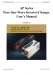
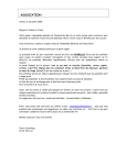
Service Manual Unit: Pellet burner Type: ROTO-NET Models: G1: 5-20 kW, 5-36 kW G2: 10-50 kW, 15-70 kW G3: 20-100 kW, 30-150 kW G4: 30-200 kW, 35-250 kW, 40-350 kW NET New Eko Technologies 1 IMPORTED EXCLUSIVELY BY BTEK RENEWABLE ENERGY PRODUCTS - BTEKENERGY.COM - 905-939-2512 / 647-886-5107 [email protected] Contents 1. Unit Description……………………………………………………..…... 3 2. Fuel Specification…………………………………………….………….. 4 3. Construction and Operation of the Burner……………………………….. 4 4. Components……………………..………………………………………... 6 5. Assembling the Unit……………………..……………………………….. 6 6. Maintenance ................................................................................................... 9 7. Operational safety .......................................................................................... 9 8. Igniter Replacement……………………..……………………………….. 10 9. Burner Liquidation After its Service Life is Over………………………. 11 10. Burner Models, Overall and Mounting Dimensions …………………….. 12 11. Technical Data……………………………………………….…………… 13 EC Declaration of Conformity ....................................................................... 14 12. Burner Installation Protocol……………………………………………… 13. Warranty ........................................................................................................ 17 15 2 IMPORTED EXCLUSIVELY BY BTEK RENEWABLE ENERGY PRODUCTS - BTEKENERGY.COM - 905-939-2512 / 647-886-5107 [email protected] 1. Unit Description. Burners ROTO-NET series are designed for solid fuels combustion in the form of pellets with different degrees of pollution and grain size (according to this specification, point 2). The burner operates automatically and does not require supervision. Rotation of a combustion chamber prevents adhesion of slag to the chamber formed during combustion. The slag moves forward and exits the combustion chamber due to cyclic rotation. Moreover, no adhesion facilitates the cleaning process of the burner and significantly affects its service life. Combusted bed is oxygenated over the entire length of the combustion chamber, and further mixed by the rotating combustion chamber that enhances the combustion process and allows complete combustion of the supplied fuel. The burner is designed to work with central heating boilers for solid fuels, as well as several models of gas or oil boilers with a combustion chamber enabling the collection and selection of ash. The burner is an ecological device as it uses fuel from renewable sources. It also features a small demand for electricity. The burner is equipped with a controller which is responsible for an optimal dosing of fuel in accordance with the parameters set by the user, and variable speed power control. This controller operates with a room thermostat which helps to maintain the temperature in the room. The burner's controller is also equipped with temperature sensors of the boiler and DHW. The controller can be connected to circuit pumps of central heating and DHW. The burner is equipped with a safety fittings, which in the event of overheating or failure of the flame in the combustion chamber cut off the fuel supply. A break in electricity sup- ply automatically turns off the fuel supply, and the amount remaining in the combustion chamber does not result in damage to equipment and cooperating devices. The burner should be operated by power from an external storage tank for storing fuel, using a helical transport system, that is the fuel feeder tray. The burner should only be supplied by fuel specified in point 2. 3 IMPORTED EXCLUSIVELY BY BTEK RENEWABLE ENERGY PRODUCTS - BTEKENERGY.COM - 905-939-2512 / 647-886-5107 [email protected] 2. Fuel Specification. The burner should only be supplied by fuel with the following properties: Fractions Diameter Length Dust fraction Density Moistness Calorific value Ash content grain size 6-8 mm 5-10 mm < 10% 600 ÷750 kg/m3 5÷15% 14÷19 MJ/kg ≤ 7% Nominal power of the burners is given for the use of pellets produced in accordance with DIN or DIN Plus Specifications. For pellets with other parameters of combustion, in particular with a different calorific value, ash level and moisture - the power may be lesser. 4 IMPORTED EXCLUSIVELY BY BTEK RENEWABLE ENERGY PRODUCTS - BTEKENERGY.COM - 905-939-2512 / 647-886-5107 [email protected] 3. Construction and Operation of the Burner. Block diagram. No. 1. 2. 3. 4. 5. 6. 7. 8. 9. 10. 11. 12. 13. 14. Description Rotary combustion chamber Aeration chamber Thermal insulation (option) Flexible pipe connector External tray fuel feeder External fuel tray (option) Pressure chamber Fuel feeder into the combustion chamber (stoker) Igniter Controller Mechanism for combustion chamber rotation Fan Front support roller Elbow Connection 5 IMPORTED EXCLUSIVELY BY BTEK RENEWABLE ENERGY PRODUCTS - BTEKENERGY.COM - 905-939-2512 / 647-886-5107 [email protected] Construction and Operation of the Burner ROTO-NET burner is built with connected modules and metal sheet components. Components exposed to high temperatures are made of stainless and heat resistant steel, other elements are protected against external factors by galvanic coating or painting. External fuel feeder (5) is made of stainless steel tube. The burner consists of the essential elements specified in the schema. The burner starts the operation by fuel supply from the external tray (6) by an auger feeder (5) elastically connected with the burner. Then the amount of fuel is supplied by the auger feeder (8) into the combustion chamber (1). After delivery of the appropriate amount of fuel, the igniter (9) initiates ignition. After the ignition burner goes into continuous mode in accordance with the specified external parameters. The air necessary for the combustion of the fuel is supplied by fan (12) via the aeration chamber to the combustion chamber, and some portion of air is also supplied through the pressure chamber which provides cooling of the heater. The air intake to the burner is located in the bottom part. Cyclic rotation of the combustion chamber carried by the drive 11 takes place during the operation. The frequency of rotation is adjustable. Combustion products move to the front of the burner and exit it, then accumulate in the ash pan of a connected central heating boiler or another boiler adapted to work with the burner. Burner is fully automatic and adjustable. Fuel is automatically drawn from the tray, depending on the demand for thermal power. In the event of exceeding set limits burner goes into standby mode. The transition from standby mode to operating mode is also automatic, the burner goes into ignition mode and then again in the continuous mode. The intake air quantity is closely related to the amount of fuel delivered for optimum combustion and does not cause an excessive cooling of the combustion chamber. Operation of the burner in based on providing an appropriate amount of fuel and on removing products of combustion - ash. The burner is equipped with safety fittings. The first is a photocell, which is responsible for detecting the presence of the flame and its absence cuts off the fuel supply. The second safety element is a temperature sensor placed in the pressure chamber, which breaks fuel sup- ply from the main tray in the event of ignition of the fuel dose inside the auger feeder supplying fuel to the combustion chamber. 6 IMPORTED EXCLUSIVELY BY BTEK RENEWABLE ENERGY PRODUCTS - BTEKENERGY.COM - 905-939-2512 / 647-886-5107 [email protected] 4. Components. The burner is supplied with the following components: 5. ROTO-NET burner along with the controller, Auger feeder from the external tray to the burner, Flexible hose, 0.75 m length, to connect the burner with the auger feeder, Elbow connection Central heating boiler temperature sensor with wiring, DHW temperature sensor with wiring, Screws. Assembling the Unit. Usually, the ROTO-NET burner is connected to the already working installation of the boiler. Depending on the design of the boiler, the connection is mounted to the furnace door. The burner must be placed in a location that allows easy access to the burner and enables installation to the boiler door. This solution provides easy cleaning and a possible review of the hearth. In the event of too small width of the door, the burner shall be mounted asymmetrically - closer to the hinges. If this proves to be insufficient, use the spacer plate. It is also possible to mount the burner to the custom door - in every such case, however, it shall be consulted with a service technician. Burner installation should be performed by the service technician authorized by the manufacturer. Installation work should be completed with an installation and commission protocol. 5.1. Assembly Instructions. 1. Take the measurement of boiler door dimensions and determine the optimal point of attachment of the burner. 2. The burner must be placed in the central heating boiler or other heating device while maintaining dimensions shown in the following diagram and table. 3. Perform the mounting holes in the door according to specifications for particular burner. 7 IMPORTED EXCLUSIVELY BY BTEK RENEWABLE ENERGY PRODUCTS - BTEKENERGY.COM - 905-939-2512 / 647-886-5107 [email protected] 4. If required, use the spacer plate. 5. Remove the outer casing of the burner by unscrewing the screws. 6. Mount the burner in the door using screws. 7. Depending on the selected option connect temperature sensors, DHW, room thermostat to proper controller clips (see wiring diagram) - guiding the cables through the glands in the housing. 8. Depending on the selected option connect the central heating pump and DHW pump proper controller clips (see wiring diagram) - guiding the cables through the glands in the housing. 9. Install the burner housing, and tighten the screws. 10. Place the pellet tray next to the boiler, insert the fuel feed conveyor and hang by the handle beside the auger drive. 11. Ground all metal parts connected to the igniter and carry out effectiveness measurement of grounding and zeroing. 12. Put the elbow connection on the burner, and connect the elbow with the fuel feeder using a flexible hose. Flexible pipe length can be adjusted by sliding it forward and backward on the combined elements. Keep the angle of decline in consumption of no less than 450. 13. Connect the power cord of the fuel feeder into the appropriate slot in the burner. 14. Connect the electrical cord of the burner to a grounded electrical outlet. 15. Fill the tank with fuel. Wiring diagram of the burner. 8 IMPORTED EXCLUSIVELY BY BTEK RENEWABLE ENERGY PRODUCTS - BTEKENERGY.COM - 905-939-2512 / 647-886-5107 [email protected] Model Power range [kW] 5-20 5-36 10-50 15-70 20-100 30-150 30-200 35-250 40-350 G1 G2 G3 G4 A minimum of [cm] 25-35 35-45 45-55 55-75 After connecting and starting the burner, the technician should train the user for the correct operation of the device, refer to possible controller settings and behaviour in case of an emergency and how to eliminate it. The boiler room should meet certain conditions regarding the safety and protection of fire protection. In particular, there should not be stored flammable materials and substances. The ventilation system should meet the minimum requirements specified in the following table: Power range [kW] up to 30 30-60 60-2000 Cross section of the air supply [cm2] (Diameter [cm]) 200 (ø16) 300 (ø20) 5 cm2 per 1 kW of power, not less than 300 cm2 Cross section of the exhaust air cord [cm2] (Diameter [cm]) 200 (ø16) 200 (ø16) equal to at least the midsection of the supply cable, not less than 200 cm2 The central heating should be filled in the required range - i.e. should have appropriate pressure and the value shall be specified in the boiler's instruction manual. This installation should be vented. It is forbidden to use the igniter without safety guards. 9 IMPORTED EXCLUSIVELY BY BTEK RENEWABLE ENERGY PRODUCTS - BTEKENERGY.COM - 905-939-2512 / 647-886-5107 [email protected] 6. Maintenance. In order to ensure trouble-free operation, as well as to extend the life of the burner, the following steps should be applied: 1. The hearth should be kept clean - through its regular cleaning. The frequency of cleaning depends on the quality of the fuel. On average, it should be performed once a week. 2. Use only the fuel recommended by the manufacturer. 3. It is not allowed to burn in the burner materials not intended for the burner. 4. Provide adequate amount of fresh air. Maintenance must be strictly performed on cooled down burner disconnected from the power source. 7. Operational Safety. In order to ensure the safety of the user of the burner, the following steps should be applied: 1. During the operation of the burner, do not open the door of the boiler with a burner mounted therein. 2. In the event of ignition of fuel inside the burner it should be immediately unplugged from the power source and only then eventually any firefighting operations can be carried out. 3. Keep the boiler room clean and do not store there any unnecessary items. 4. The burner should be operated by adults with accordance to the Service Manual. 5. The burner, boiler, central heating and DHW should be kept in good condition. 6. Pay particular attention to the tightness of the water in the vicinity of the burner - any spills can damage the burner, as well as increase the risk of electric shock. 7. The burner and tray are equipped with rotating parts - do not insert hands, fingers or other objects into during their operation. 8. It is not allowed to interfere with the burner automation systems and other electrical devices installed in it. 10 IMPORTED EXCLUSIVELY BY BTEK RENEWABLE ENERGY PRODUCTS - BTEKENERGY.COM - 905-939-2512 / 647-886-5107 [email protected] 9. The burner is a device generating heat - some of the elements of the burner can be heated - use caution in contact with them. 10. It is forbidden to use the burner connected by the user himself. 11. It is not allowed to connect the burner to not adapted boiler. 12. The burner cannot function as an independent unit. 13. It is not allowed to place items on the burner. 14. It is not allowed to use other methods of ignition in particular, the use of flammable materials. 8. Igniter Replacement. The igniter is the element of the burner undergoing failure the most often. R eplacement it is possible by the user according to the following procedure: 1. Disconnect the burner from the power source and, if necessary, wait for it to cool down. 2. Remove the fuel feed elbow. 3. Remove the outer casing of the burner by unscrewing the screws. 4. Slide the driver pressing the elastic clips on its sides - do not use tools. Be particularly careful not to break the cables out of the clips. 5. Unscrew the wires supplying the power to the heater from the appropriate clips of the controller marked on the wiring diagram. 6. Unscrew the heater adapter plate - located in the right lower part of the connection plate. A cord supplying the heater passes through the plate. 7. Pull the adapter plate from the burner by sliding it along the cable. 8. After removal of the cover plate through an opening, take out the heater. Pliers can be used. 9. Place a new heater in the same place by inserting it into the slot inside the burner, until a clear sense of resistance. The heater should be securely seated in the slot and should not cease outside the connection plate. 10. Pass the power cord through the adapter plate - through the rubber gland. 11. Screw the adapter plate to the mounting plate, the wire should be slightly stretched. 12. Screw securely the heater cable to the appropriate clips on the controller. 13. Insert the controller back to its place. Elastic lamina should be on the inner side of the housing. 11 IMPORTED EXCLUSIVELY BY BTEK RENEWABLE ENERGY PRODUCTS - BTEKENERGY.COM - 905-939-2512 / 647-886-5107 [email protected] 14. Place the outer cover and secure it with screws. 15. Install the fuel feed elbow. 16. Go to the Assembling of the Unit section. 9. Burner Liquidation after its Service Life is Over After exceeding the service life of the igniter it should be utilized according to the requirements of environmental protection. 10. Burner models, Overall and Mounting Dimensions. 10.1. ROTO-NET 5-20 kW and 5-36 kW - model G1. Power Range Hearth Diameter SA Mounting Diameter SM 5-20 kW 5-36 kW Ø 102 mm Ø 102 mm Ø 139,7 mm Ø 139,7 mm The length of the combustion chamber A 220 mm 245 mm 12 IMPORTED EXCLUSIVELY BY BTEK RENEWABLE ENERGY PRODUCTS - BTEKENERGY.COM - 905-939-2512 / 647-886-5107 [email protected] 11. Burner's technical data. Parameter 1. 2. 3. 4. 5. 6. 7. 8. Power Power supply Average power consumption Igniter's power Combustion efficiency Boiler efficiency Power Adjustment Operation of the central heating pump 9. Operation of the DHW 10. Burner control by room thermostat 11. Burner control with a weather compensator 12. Pellet feeder 13. Brandling pipe 14. Required chimney draft Models G1 5-20 kW G1 5-36 kW 5-20 kW* 5-36 kW* 230 VAC, 50 Hz (6 A) 50 W 60 W 200 W > 99 % > 96 % YES (power modulation correctly the burner) YES YES YES YES (option) YES (Ø70 x 2000 mm) YES (Ø70 x 750 mm) 5-15 Pa * - nominal power of the burners is given for the use of pellets produced in accordance with DIN or DIN Plus Specifications. For pellets with other parameters of combustion, in particular with a different calorific value, ash level and moisture - the power may be lesser. 13 IMPORTED EXCLUSIVELY BY BTEK RENEWABLE ENERGY PRODUCTS - BTEKENERGY.COM - 905-939-2512 / 647-886-5107 [email protected] DECLARATION OF CONFORMITY NET New Eko Technologies Grzegorz Pilarczyk Nieradowice 58, 48-385 Otmuchów, Poland declares that: the Pellet Burner unit, type: ROTO-NET, model: G1: 5-20 kW, 5-36 kW meets the requirements and is compatible with: 2006/42/WE, 2006/95/WE, 2004/108/WE, and complies with the following harmonized standards: PN-EN 953+A1:2009, PN-EN ISO 13732-1:2009, PN-EN 60127-1:2008/A1:2012, PN-EN 60445:2011E, PN-EN 60519-1:2011E, PN-EN 60730-2-5:2006/A2:2010E, PN-EN 60730-1:2012E, PN-EN ISO 12100:2012, PN-EN 61000-6-3:2008, PN-EN 60730-2-9:2011, The person authorized to compile the technical file is: Szymon Bajerlein. Nieradowice, 25 Feb 2014 Grzegorz Pilarczyk 14 IMPORTED EXCLUSIVELY BY BTEK RENEWABLE ENERGY PRODUCTS - BTEKENERGY.COM - 905-939-2512 / 647-886-5107 [email protected] 12. Burner Installation Protocol. Customer's Data Name: Address: Phone: E-mail: Seller's Data Company Name: Address: Phone: Fitter's Data Company Name: Address: Phone: Installation Date: Installation Data Burner type/model: Serial Number: Power: Year of production: Boiler: Year of production: Boiler power: 15 IMPORTED EXCLUSIVELY BY BTEK RENEWABLE ENERGY PRODUCTS - BTEKENERGY.COM - 905-939-2512 / 647-886-5107 [email protected] Data on the burner settings at the time of installation Vent. rotation at MAX power Vent. rotation at MIN power The amount of fuel at MAX power The amount of fuel at MIN power Hearth brightness for the flame failure Hearth brightness for ignition Hearth brightness till the igniter turn off A number of hearth ignitions Data on the burner settings at the time of installation Vent. rotation at MAX power Vent. rotation at MIN power The amount of fuel at MAX power The amount of fuel at MIN power Hearth brightness for the flame failure Hearth brightness for ignition Hearth brightness till the igniter turn off The results of the gas analysis Exhaust temp. MIN power Exhaust temp. MAX power CO2 emissions at MIN power CO2 emissions at MAX power Chimney Draft Excess air ratio l Efficiency I have read this Service Manual, understand its content, I accept the conditions of the warranty. I have been trained to operate the burner. Date: Customer's signature: …………………………………………………… …………………………………………………… 16 IMPORTED EXCLUSIVELY BY BTEK RENEWABLE ENERGY PRODUCTS - BTEKENERGY.COM - 905-939-2512 / 647-886-5107 [email protected] 13. Warranty. 1. Net New Eko Technologies through Btek R.E. Products , provides a 36 month warranty for the smooth operation of the ROTO-NET Burner to the extent described in this Service Manual, starting from the date of the Burner installation (with the exception of point 2). 2. The igniter warranty lasts for a period of 2 years of 800 ignitions. 3. Defects found during the warranty period shall be removed within 21 working days from the date of filing the complaint. 4. Any defect disclosed during operation must be reported promptly. 5. Documents required to perform free repairs are: completed Installation Protocol and proof of purchase of the burner. 6. Warranty Card is not valid in the case of absence of the required stamps, signatures and dates. 7. Completed installation protocol should be sent to the manufacturer within 14 days from the date of installation of the burner in paper or electronic form. 8. The first run of the burner and setting the operating parameters is the one carried out by an authorized service technician. 9. Warranty will not apply in the case of: installation, operation or use of the burner conducted not in accordance with this Service Manual, any changes or burner modifications, starting the burner without its installation in the boiler, too small cross section of the chimney or to narrow chimney draft, repairs by persons not authorized by the Manufacturer, malfunction of the electrical system, incorrect parameter setting of the burner, combustions of fuels not included in the Manufacturer's specifications, the impossibility to access the installed burner. 10. Warranty does not cover: adjustment of the burner parameters, cleaning and maintenance. 11. Costs of service calls for repairs related to paragraphs 9 and 10 shall be covered by the customer. 12. Complaints should be reported: by mail, electronically or by fax. 17 IMPORTED EXCLUSIVELY BY BTEK RENEWABLE ENERGY PRODUCTS - BTEKENERGY.COM - 905-939-2512 / 647-886-5107 [email protected]