1
..-::)
j
,,
r10DEL ONE HCME COMPliTER
SERVICE rWJUAL
-)
.
"•
•
J
.
.�
·_.-· . · )
..
.
Table of Contents
..
.
.
•
.
.
.
.
.
.
.
•
.
.
.
.
.
.
.
.
.
.
.
.
.
.
.
.
.
.
.
.
.
.
.
.
.
.
.
.
.
.
.
�
.
1
'IX'otlble wca:tor Ci"la.r't.
•
•
•
•
•
•
•
•
•
•
•
•
•
•
•
•
•
•
•
•
•
•
•
•
•
•
•
•
•
•
•
•
•
•
.
•
•
•
•
•
•
•
•
4
Inttoouct.ion
.
.
.
•
.
.
.
�
.
� �sanbly R.anc1V'a.l and In.s'ta.llation.......................... 6
.
.
•
.
.
.
•
.
.
.
12
cassette Transprt Sub-assembly Ranoval and In.s'"..a.llation
•
.
.
.
.
.
.
.
.
12
Control Panel Sub-assanbly Re!rova.l and Installation
•
.
.
.
AC Power Adaptor Sub-assembly Raroval and Installation
•
•
•
.
•
.
.
.
.
.
.
15
Main Electronics Sub-assanbly Raroval and Installation
.
.
.
.
.
.
.
.
.
.
.
15
Tape Head Alignment Procedure
.
.
•
.
•
.
.
.
.
.
.
•
.
•
.
.
•
.
•
•
.
•
.
•
•
•
•
•
.
•
•
•
.
.
•
.
l8
Service Manual Addendum
C,i,r'cu.it Eoal:d
�s.. . .. . ................... ........... . 21
Test Tape Instructions
.
•
•
•
.
•
•
•
•
•
•
•
•
•
•
•
•
•
•
•
•
•
•
•
•
•
•
•
•
.
•
.
•
©
•
•
•
24
1979 by lntercct :Jecronics, !n'-
'�
.. ,: ·- .: )
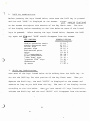
Introduction
facilitate
In order to
rapid diagnos i s and reptir
of the l-t:del One Bane
canputer,
Interact has designed the system as an assenbly of ei ght sub-assanblies ar
''m:::dules".
Each moi111e ccntains the c::anp:ments which perfom a specific system
Tile servicep!rs::m 's resp:msibility is to i�· the
function.
and replace it.
All
fault".! m:dule
No further repairs should be attempted at the service center.
faulty nrxjnJes
are to be returned to the
factcry with
a
o=rnpleted Fac:tcry
Service T a g.
The prcx::es s of identifying a malfunctioning
rccdul.e
the "Trouble locator Chart" on pages 4 and 5.
.·:·_:_·)·
ccmnon
�of
each.
To ccnfll:m that
is simplifie::i U.f the use
of
This chart contains the IICst
DXXiule failure and lists the� pro:edure appropriate for
a suspected mcdule
� not listed on the chart ,
Instructions for use of the test
is
load and
f aulty
rim the
ta;::es �m on
or to locate the cause of
Interact'IH
8K
or
16K T est Tape.
page 23 of this service manual .
Once the servicepers:ln has detennined that a mcdule is
faul ty , he should
ret:urn
that rncdule to the factory for repair and prOV"ide a Factory Service Tag to ac
o::::rtJi.='S.IY it.
manual.
An example of the Factory Service Tag is sh::Mn on page
It is essential that all items sl:Dr.m on
!<bre tags can be obtained
by proto-copying the
the tag be filled
example on page
3
3 of this
out o:::mpletely.
or
by writ.i.n;
Interact Electronics, Inc., P.O. Box 8140, AnnArl:r
:o , Hichigan 48107.
Faulty mod ul e s
should be mailed to:
In teract El ectroni c s,
2548 Packard Road
Ann Arbo r , MI 48 1 04
AT TN:
Servi c e Dept.
Inc.
1
(·�
.
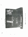
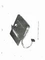
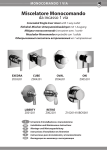
The parts of the !·bdel One systan are identified in Figure 1.
figures in this manual depict the disassembled mcdules.
. /
The remaining
The basic eight
mcdules are as follows:
1.
Joystick assembly
2.
Antenna switch J:::ox ( 2 of Figure
3.
Fe. p::rw-e.r adaptor
4.
!.ower rousing sub-a.ssanbly. (Figure 2)
5.
Upper
6.
Control panel sub-assanbl�r" (Figure
7.
Cassette sub-as.sanbly (Figure 8)
8.
�.a.in elect..�nics sub-assanbly (Figure
(1 of
(3
Figure
of Figure
1)
1)
1)
musing sub-assembly (Figures
2
3,4 and 5)
6)
10)
(
)
I
I
>
1,11
1,11
Ill
3
cr
3
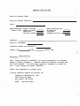
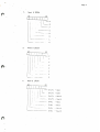
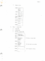
FACTORY SERVICE TAG
Service Center N ame:
Service Center Address:
D ate:
Sub-Assemb ly:
(Check One)
M ain electronics
AC adaptor
Joystick
Antenna swit ch box
Upper housing
Lower housing
C assette
Cont rol p anel
Symptom:
D ate of P urchase:
#
Inter act Mode l One Serial
t�ernory
8K · ------ ' 16K
------�
Check One
·-·)
1.'.-
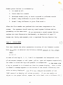
Shioping Instructions
P ack f a ulty modules c areful ly in secure p ack aging to prevent
damage during shipment.
Fnclose separ�te F actory Service T ag
.for e ach module.
Be sure that specific symptom is noted on
M ark shipping c arton "FRAGILE".
t ag.
Never m ail modules by parcel post.
Faulty modules
should be mailed to:
Inter act Electronics,
2548 Packard Roa d
An n Arbor, M I 48104
ATTN:
Service Dept.
Inc.
.
.·.
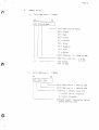
Symptom
but
No picture or sound and
no pilot light
No picture or sound
light is on
Poor picture and/or sound
No color
Cassette transport doesn't
ru"
Cassette tapes don't read
properly
to
Repair/Replacement Procedure
Replace AC Adaptor
15)
Probable Location
Replace Upper
(Page
15)
Assembly
(Page
15)
AC Adaptor
Replace Main Electronics
(Page
(Page
ON-OFF switch
Electronics
alignment
Replace Main Electronics
(Page
Replace Transport Sub-assembly
15)
15)
15)
12)
12)
(Page
(Page
Replace Control Panel Sub-assembly
6)
Main Electronics Sub-Assembly
Repiace Main
15)
or
If TV set is properly tuned,*
(Page
main electronics out of
Replace Main Electronics
If TV set is properly tuned,*
main electronics clock out of
failure
adjustment or main electronics
voltage
Control Panel Sub-assembly
or
Motor faulty
or
(see Owner's
Motor not getting
Clean Tape Head
(Page
"'
(Page
(Page
Guide)
Tape head dirty
(Page
(Page
19)
Align Tape Head
18,
Tape head out of alignment
or
Electronics
Replace Main Electronics
Replace Control Panel Sub-assembly
Replace Main
Heplace Transport Sub-assembly
circuitry faulty
'l'ransport mechanism binding
or
Read
or
Main electronics faulty
Keyboard faulty
or
0.
be adviseable to try the unit with a different TV set.
function
It may
Keys on keyboard fail
*
�\ :) �.'
�'
(.b,
12)
12)
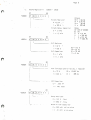
Symptom
Sounds not clear due to
excessive hum
mittent dots
TV Screen has inter
Probable Trouble
Location
If TV set is properly tuned,*
main electronics out of
Replace Hain Electronics
(Page
(Page
15)
15)
Repair/Replacement Procedure
or
main electronics failure
Replace Main Electronics
alignment
Intermittent memory-RAM failure
Replace Transport Sub-assembly
Replace Main Electronics
(Page
(Page
15)
15)
(Page
Read/Write switch dirty
Read/Write circuitry faulty
Replace Main Electronics
or
Main Electronics failure
tion back on tape
Unable to write informa
Unit fails after short
period of time
d
12)
Replace door in track
5
(Page
Cassette Housing
''-·--"
. 1
It may be adviseable to try the unit with a diff erent TV set.
Cassette door pops out of
track
*
�;
12
·. ·�
1.
tTDoer Jl.ssembly Remo�Tal and Installation
In order to remove any module from �,e computer console, this
orocedure mu�t be com"Oleted first:
-
-
1.
Turn the
Interact unit over so that the bottom of the
lower assembly is
showing,
as in Figure
2.
Place it on
a soft surface to avoid marring the unit.
2.
Remove the
six
(6)
screws at the corners and top and
bottom center of the lower housing.
3.
Carefully holding the top and bottom as semblies together,
turn the unit back over
as in
4.
Figure
so that the control panel is up,
3.
Lif t the upper assembly up at approximately
that the internal cable s are exposed,
5.
45 o angle so
in � igu re 4.
Remove all connections and free �,e upper as se� ly as i�
Figure
6.
as
a
5.
The upper a sse�ly c�� be installed by.reversing steps 1
through
5,
b eginni n g wi�� step
6
5.
• ""\
.. )
·:)
:::::
0
c
VI
(
7
,)
aJ
c:
0
)
8
..,
C"
c
::=J
1"'1
�
I
I
c:
"
"
('1)
..,
')
>
Ill
Ill·
('1)
3
r::r
-<
�
Ql
,...
..,
-<
0
"
('1)
::I
)
9
c:
11)
0.
0
,..
:;,
Ll.
,..
-)
..0
e
11)
VI
VI
�
<
::I
z
I..
11)
0.
c..
:;)
c:
ttl
E
I
I..
11)
c:
I
1.1'\
c:
U.J
0:::
:;)
�
Ll.
)
10
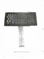
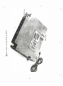
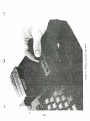
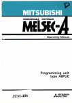
FIGURE 6--Control
Panel
11
Sub-assembl y
2.
Control Panel
1.
Sub- assembly Remov al
Complete procedure
1
on p age
6
and Inst all ation
(Upper
Assembly Removal
and Installation).
2.
Remove the two
(2)
tinnerm an nuts shown in
the Control P anel Sub- assembly
(see Figure
Figure
6) .
5.
Lift
C are must be
taken in removing the nuts because too much stress will
cause
the locating pl astic pins to break.
The nuts can be
removed quite e asily by using long nose pliers
and pinching
the ends toward the pin.
3.
The Control P anel Sub-assembly c an be installed by reversi�g
s teps
3.
J
·: · J
1
through
2,
beginning
at step
C assette Transport Sub-assembly Remov al
1.
Complete procedure
1
on p age
6
2.
an d Install ation
(Upper Assembly Remov al
and
Inst all ation).
2.
Remove the transport br ackets shown in Figure
7.
Lift
the c assette tr ansport out of the transport housing.
( See Figure
3.
The
8.)
C assette Tr ansport Sub-assembly c an be installed by
reversing steps
4.
1
and
2,
beginning
at step
2.
Cassette door c an be inserted b ack in track by loosening
the tr ansport br ackets
has enough sl ack
(Figure
from upper
7)
until tr ansport housing
assembly to allow pivot arms
of c assette door to slide into tr ack notch.
easier to do this with door spring removed.
)
12
It is usu ally
FIGURE ?--Cassette Transport
13
In Housing
)
·�
.· · )
...
1..
0
Q.
11'1
c:
ro
1..
1-
•.
�
...
...
�
11'1
VI
ro
u
I
I
co
)
14
4.
AC. Power Maotor Sub-asser.lblv Rerroval and Installation
1
1.
COnplete procedure
2.
R.Em:::lve each of the five
on ,;age 6
(5)
(Upper
Assembly Ranoval and Installation).
wires on the AC adaptor o:m:1 shown in
Figure 9.
3.
Renove the card clamp fran the
top
of the Main Electronics Sub-a.ssanblv.
Ran::lve the AC. adaptor fran the lower assanbly.
4.
The N:.
adaptor assembly can
be;inning at
step 3.
be installed by reversing steps 1 throuqh 3,
Make certain color code of wiring is
Note:
fol.lowed-D::cm left to right:
White, Black, Orange, Red , Blue
5.
Main Electronics Sub-assembly Ratoval and Installation
1.
Ccrnplete procedure
2.
.Remove the four
(4)
1
on page 6 (Upper Assembly Ranoval and Installation).
screws
sh:Jwn in Figure 9 and lift the Main Electronics
Sub-assembly out of the lower assembly.
3. · The l-1..ain Electronics Sub-assembly can
1
through 2, beginning at step 2.
15
(See Figure
10.)
be installed by r eversing steps
>..c
�
U'l
U'l
c:t
.)
"0
�
0
u
�
0
J.J
�
QJ
3:
0
....J
I
I
0'\
QJ
"0
0
u
UJ
a:
::r
�
�
0
0
u
""-
..:.:.
c. u
t1l QJ
"0 �
<t u
u
<t
UJ
10
:z
. · ,�:\
··y
16
0
I
I
�
VI
�
�VI
n
�
,.,
�
n
,..,
�
0
�
n
VI
VI
c:
c1
Ql
VI
VI
�
3
c-<
( )
17
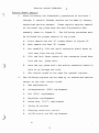
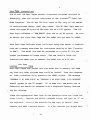
6. 0 Tape Head Ali£?rnent Procedure
This procedure can be accomplished only after all system faults have
:�
been resolved according tc sections 1 ��rou9h 5 of this manual. The
equipment necessary to perform a head alig�ment includes:
Interact Head Alignment Tape
Television Receiver
Antenna Switch Box
Small Phillip's Head Screwdriver
Begin by connecting ��e Interact computer console to the television
as described in ��e Model One Owner's Guide.
Proceed as you would
for normal operation by completing the following steps:
1.
Turn
2.
Depress the button labelled BESET.
3.
Confirm that the message DEPRESS L TO LOAD appears on the
en
screen.
>)·
· · .
��e power ON/OFF switch.
If ��is message does not appear on the screen, a
system fault exists and must be repaired before alignment
can be perfo�ed.
4.
Load the Head Alignment Tc.pe into the cassette holder
the o-....-ner' s Guide for details)
the keyboard.
and depress the lett.er "L" on
Press the REHIND cassette button and allcw a
few seconds for the tape to rewind.
button.
t see
Press the READ cassette
The cassette spindles should begin to turn slowly. As
the tape reads in, a steady tone is produced.
Insert the
small Phillip's screwdriver into the access hold in the
cassette transport housing
5.
(see Fiqure 11. )
�men sound is heard through 7V set, adjust fine tuning of TV
set for optimum sound quality.
18
6.
Rotate the screwdriver clockwise and counter-clockwise while
listening to the sound.
:
)
The sound should peak at maximum
level within a quarter turn in either direction.
Stop at a
point where the peak is reached.
7.
Attempt to load a standard Interact application cassette
into the system.
(See ��e Owner's Guide for details.)
If the preceding ali_gnment procedure has been accomplished
correctly and the casse�te is not defectiye, no further
loading difficulty sh ould occur.
8.
Since the head alignment screw will move with usage and
time, it is best to place a drop of liquid scre't-1-tight
(e.g. LOC-TITE) on the screw head and mating surface. This
. can be accomplished by removing the cassette tape and
pressing the "READ" button.
the door opening.
This moves the head tmt�ards
Now with a mirror and a small �rush,
a drop of liquid screw-tight can be applied to the scretv
head surface.
19
:;_)·
·.:·.•,··
··.
· '7\
.
j
.�
:J
<
I
I
.··�)
···
. ·
Service �anual Addendum
Circuit Board Repairs
1.
After following t�e disassembly procedures of sections l
through 5, certain furt�er repairs can be made by factory
authorized service centers.
T�ese repairs require removal
of the metal top plate from the Main Electronics Subassembly shown in Figure 10.
The following procedure must
be followed for proper removal of top plate:
A.
First remove the six "A" scre•,.;s shown in Figure 10.
B.
Next remove the four "B" screws.
C.
NmV' carefully lift. t."le small connector board about an
inch away from the top plate.
D.
Tilt the left front corner o f the connector board down "
into· the top
E.
plate hole.
Move the top plate until the entire connector board is
able to go through the hole.
F.
2.
The circuit board is now open for general repairs.
The following repairs can be made by an authorized service
center on the main circuit board.
A.
RAM replacements
B.
��croprocessor
C.
ROM
D.
Regulator replacements
E.
Sound chip
F.
Tuning RE' section
G.
Cleaning read/write switch
H.
ON/OFF switch and LED replacement
(2316)
(8080) replacement
replacement
(76477)
·)
. .
21
replacement
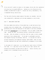
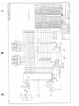
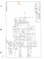
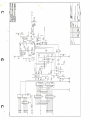
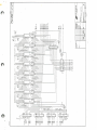
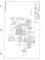
A diagnostic .RCt--1, suppxt jurrq:::er cables and repair data will l:e made available
to th:lse service centers who are authorized to make roard repairs.
:
)
Repair
data will IDcl.ude block diagrams, schematics, parts lists and waveform
analysis to facilitate service repair.
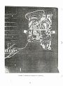
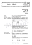
Figure 12 shows the locations of rrost of the cnnp:ments mentioned above.
-.
Care must l:e taken in ren:lV'al, handling and insertion of any chips on the
l:oard
1.
as
follows:
Ren::Jve chips with the aid of a chip ratDVal teal, carefully
observing
orientation before raoova.l.
2.
Handle all chips with grounding strip on wrist to prevent static electricity
)
fran burning· out the chip.
3.
l-1ake certain � is not applied when chips are rem::wed or inserted.
4.
Carefully insert chip with the proper orientation.
22
N
w
v
(8)
RAMS
FIGURE
�
+5V REG
12--Main Electronics Sub-assembly
SOUND CIIIP
v
- Top Plate Removed
'
,;;)
.
: ·· )
'...;...,/
�
•
Test Tape Instructions
The 8K and 16K Test Tapes contain integrated programs designed to
thoroughly test the various subsystems of the Interact™ �1odel One
The SK and 16K Test Tapes ·differ only in. the amount
Home Computer.
of random-access memory (RAM) they check.
The 8K Test Tape does not
check the upper SK bytes of RAM when run on a 16K system.
The 16K
Test Tape indicates a "RAM ERROR" when run on an SK system.
Be sure
to select the right Test Tape for the Model One you want to check.
Each Test Tape includes eight individual subsystem tests, a combined
test and a memory exerciser for continuous testing of RAM ("burning
in RAM").
The Model One must be connected to a color TV for the
proper performance of these tests.
See the Owner's Guide for
instructions about how to connect the Model One to a TV set.
Loading the Test Tape
Both Test Tapes are loaded into the Model One in exactly the same
way that any other program tape would be loaded.
Turn the computer
on, then initialize it by pressing the RESET switch.
The message
"DEPRESS L TO LOAD TAPE" or "DEPRESS L TO LOAD TAPE, R TO RESTART"
should appear on the TV screen.
If it does not, the Model One is
defective and should be returned with a completed Factory Service
Tag for service.
Place.the appropriate Test Tape in the cassette drive and close the
cover firmly.
Depress the RE'NIND cassette button and type an
the keyboard.
Allow a few seconds for the tape to rewind, then
depress the READ cassette button.
24
"
L"
on
In a few seconds you should hear
,·:J
)
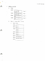
HZ leader <:one f o llowe d !Jy approxi:na':ely one minutes o£
a 600
<:l'le �odel One
waits
for
about
�isplays tl'le test �enu shewn
two seconds,
clea=s
t!:e sc=een,
.....
�...:;.en
�elow:
?.A.S.T.
O=ROt-1. CHECK
l = Rl--� CEEC!<
2=Kl3D C:SC:K
3=KZY
CEEC:K
4=JOYSTK CEECK
S=SOUND CHECK
6=COLOR CHECK
7=R/W TAPE TEST
S=':'OTAL CHECK
9=MEMEX
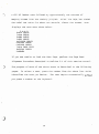
If you are unable to load
the Tes<: Tape,
Alig��ent P=ocedure desc=ibed in
.)
The
;:m=pose o£ each of
pages
.
To
select
the above
a test,
press
identifies ��e test you desi=e.
you press a n��er on
t�e
Section
per£o� t�e Tape
6.0 of <:::is service �an�al .
tests is desc=ibed
<:::e
Tl'le
keyboa.!:'d.
Head
�Q�ber f=orn the
in
t!'le following
above
list whi=�
-:.est �egins aut.cmat.ically
Test
I�
.
0: ROM CHEC�
j
This test automatically checks the read-only memo ry
A "checksum"
as sociated circuitry.
(Rat1)
and i �s
is computed by adding toget he r
the contents of successive memory locations.
The resultant sum is
compared to a value contained in the RO� test program .
If t!le
computed checksum is correct the menu is again displaye d on
If the sum if incorrect the message
screen.
"ROM ERROR"
t:."le
appears
on the screen and remains for approximately two seconds before t�e
menu is displayed again.
If the ROM ·is faulty,
-
1 5.
Return
Factory
Service
Electronics Sub As semb ly �s eescribed on page
F.lectronics
Sub-Assembly \-ri t:.lo].
completed
a
further tests can be performe d if t:.lo].e
replace the Main
the Main
Tag.
�a
RO� is not func�ioning
p rope rly.
Test
1:
Rk'1
CSEC�
This test automatically
associated circuitr].
patterns into each
checks the random-access memory
The Model One writes
pattern is not ::-ead back co rr ec-tly the message
each memory
location,
on the screen.
If
,
the n
appears
�"le tes t menu is
Fa ctory Se rvi ce Tag
.
if t!le ?�� is �at functioning ?roperly .
26
for
rea�pears
::-eplace t!le �ain Electr�nics
Sub-Assembly as d escribed on ?age 15.
a completed
"?�i..'-1 =:RF.OR"
no message is displayec ��d the menu
t:.�e �� is f au lt y
its
If a da ta
If ��e correct data patterns are read back
displaye d again.
and
four different ca ta
RAl·1 location then reads them back.
on the screen for approximately two seconds,
(��)
Retur�
t:.�e Sub-Asse��ly with
( ':
.)
\ ...... .
.
Test
2:
KLYBOJl..P.D C::ECK
T�is program,
c onj unction with Te st
i�
below,
3
ke yboard key and its associated circuit �!
checks each
When t�is
·
test
i�dividual
is selected
a patte � ==presenting the k eyb o a=d w ith t�e approp=iate symbol fa=
is displ ayed on t.."le screen.
each key
as
l.
Press the
l e ft S hi .: t ke y ,
2.
Press the
lef't cor:1er of t..�e space b ar ,
3.
Press each
As eac�
operator should
follows:
Shi.:t key.
t:...�e =igh't
then
t�en
t.."le right corner.
remaining ke y on t�e key bo ar d one key at a time.
is pressed its correspond ing symbo l
key
bl��ed out wi��
a white squ are.
observe that the
each key is depre ssed .
····)•
Proceed
on the screen is
Dur in g th e k ey bo ard check the
proper
symbol
is blanked ou't as
a fault exists it is p ossible for the
If
computer to read t.."le wrong
code for a key
and
-
.....
�..nere.r:ore blank
out
·· . .
t..� e wrong
s:nnbol
on the screen .
t:T?e of ke y bo ar d error can
only be
detec'ted by obser�;ing that the proper symbol is bla."1ked ot.:.-:.
as each
:<ey
When all
ca."'l
; -
-�
depressed.
keys have been successfully read a
hear::i,
be
a key
indi c a t i n g a
d is p lay
type an
"R".
and reload
I f the
t#o - s ec o n c
test
to
or keys ca.T'lnot
screen,
·)
""
'"' .!.S
'
J.. ••
�enu
ringing no�se
display.
be read they will remain displayed
keyboa r d
failure.
a ny
.: ault y keys,
"R"
key has
retur::
to
the
t�e
-:.est menu
depress the RESET button,
failed,
the ap p rop r i ate Test Tape.
27
'::' o
on
depress
the
r.:
?.ESET
then
button
If the keyboard is faulty,
·�
replace ��e Control Panel Sub-Assembly
.
as described on page
1 2.
Retu� the
faulty Control
I
l
Panel with a
completed Facto�J Service Tag.
Test
KEY CHECC
3:
2
This test is used in con j unction with Test
operation of the keyboard.
following list.
above to verify ?roper
Begin by testing each single
As each key is pressed a
"beep"
key on
the
can be heard and the
display appropriate for ��e key appears on the screen according to
the list.
Obserre t..lj,e display as each key is pressed,
that it matches t..�e appropriate list entry.
incorrect or if the pattern
If
�re:=ifying
��e display
"blinks" --ape ars once and
��en ·disappears
and reappears again--a keyboard failure may be assumed.
testing
all single keys
on
��e list,
test the LOCX,
is
Afte:=
;:\ )
SHIFT and
CONTROL combinations on the list.
If you encounter a keyboard
have
failed.
on page
1 2.
failure,
note which keys or combinations
Replace ��e Cont=ol Panel Sub-Assembly as described
Retu=n ·the faulty Control Panel 'H'ith a completed Factory
Service Tag.
28
C)
�
..· )
Sc�een
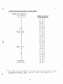
1.
Dis�lavs
for Test 3:
K�Y CEECK
Sincrle kev disolavs:
KEY PRESSED
32 2
33 3
2 6 34 4
2
3
4
10
27
25 35
24 3 6
23 37
22 38
21 39
12 3 0
11 31
15 2D
17 2:9
51 71
63 77
45 65
50 72
66 74
62. 7 9
O:l 7 5
41 69
53 6F
52 7 0
3 5 3D
02 OD
3 1 61
6 7 73
4 6 64
44 66
43 67
42 68
40 6A
5
6
7
8
9
zero
1
minus sign
?lUS sign
Q
w
E
R
T
,--
y
u
I
0
p
ec:;ual
sign
CR
A
s
D
G
H
J
K
L
semi-colon
asterisk
divide sign
l
( )When
)
asterisk
(*)
in
Sue�
33
00 2A
13 2::'
t�e last s��cl
";a�;:,age"
this list.
29
s�-:n:::cls
:I
6
7
8
9
0
1
..
Q
r..:r
.....
1:'
R
T
y
t�
I
0
?
=
.,
A
s
D
-
G
H
J
63 'K
6C L
57
56
37
some keys a�e ?�essed,
is unreccgnizeable.
iJIS?L;..Y(l.)
sc��:J
-
�
are
*
I
t�e sc�een
de!l.oteC.
dis?l.ay
":Jy an
I
Single key displays
.
(cant)
z
X
c
v
B
N
M
comma
period
question mark
space !:Jar
backspace
lock
2
( )
•
60
62
47
64
30
54
55
16
14
33
01
04
7A
78
63
76
62
6E
6D
2C
2E
3F
20
08
OS
?
z
'
:'
.. /
X
c
v
B
N
M
.
?
'It
*
? ( 2)
The LOW\ key display always begins •,.;it.'1 "LOC'K OS".
The t•,.;o
groups of numbers which follow may vary from tes� to test.
J
30
..
2.
�oc� kav combinations.
Before pressing the keys l isted below,
anC. tl'le •,yord "LOC�"
on
keys
key again and
��is sec�ion of the Key Check
varies accorC.ing to the
is pressed.
After testing ��e keys listed !::lelow,
•he word
"LOCK" should disappear
is pressed
T!;.e rest
the listed
depress tl'le LOCK
£rem the screen.
SCREEN D ISPLAY
double quotation marks
single quotation mark
dollar sign
percent sicp
exclamation poi:1t
colon
... paren·thesis
1 .. ,: .right parenthesis
"less than" sign
t...,:,an II
"greater
sign
Onderscore
Gp arrow
II
10
27
26
25
24
23
22
21
12
22
I
27
24 s
25 %
21
3A
28 (
29 )
3C <
ll 3E >
.....
15 :l.!:
17 :l.t.
__
3.
�est.
list !::le low as each of
KEY PRESSED
)
key
is C.isplayed on the screen.
��e screen ��roughout
of �1.e display
make sure the LOCX
-- -
Shift kev Combi:1aticns.
�est each of the keys listed !::lelow Nhile holdin g down the
Shift key.
�ot �se the �OCX key for this portion of the Key Check test.
depress the Shift key,
remains as
t.�e word
"Sni?T"
long as you holC. C.own
ac::ordi:1g to
�"le list below.
::elease the Shift key
and
is displayed on
t.�e key.
When vou have
t..."le ·word
31
"SHI?T"
Do
When you
the sc=een and
of
t.::.e display va=ies
�ested all
keys listed be lew,
The rest
will disap pear
==om the screen.
�-.
-
KEY PRESSED
D ISPLAY
double quotation :narks
single quotation mark
dollar sign
percent s ign
exclamation point
col on
left parentl'lesis
right paren��esis
1 0 22
27 27
26 24
25 25
24 21
23 3A
22 28
21 29
12 3C
ll 3E
15 SF
1 7 SE
"less than" sign
"greater than" sign
underscore
up-arrow
4.
\I
"
I
s
%
(
)
<
>
..
�
Control kev CornbL�ations.
Test each letter on
When y ou press
��e keyboard while
�"le Control key,
holding
the word
re?resents the
t!'le list below.
��e Control key.
appe ar s
" CONTROL "
sc=een and remains until yo u release ��e key.
varies accordL�g to
down
The rest of
T!'le asterisk
(
*
)
i.:1.
on
t!'le
t!'le display
the
.. i
.l..-.::01..
-
un.reccgnizeable symb ols prin t ed at t!'le end of eac.h
KZY PRESSED
DISPLAY
Q
51 11
63 1 7
E
R
45
w
O:::l
41
53
OS
12
14
19
15
09
OF
52
10
so
T
y
u
I
66
61
,.. -
0
p
A
s
D
3 1 01
67 13
46 04
44 06
':'
32
*
*
*
*
*
*
*
*
*
*
*
*
*
*
r: )
.j
bela•,.,
display.
•
Control key combi�ations
(c�nt)
KEY PRESSED
DISPLAY
G
H
J
K
L
z
X
c
v
N
a
M
.·
After you have
��e
reappear on
and return
)
in
If
s cree�.
the �enu a keyboard
�'1e menu display in
failed,
*
*
*
*
OB
*
oc
*
Ln.
18
03
16
*
*
*
*
OE
*
02
*
OD
" TAB"
and
�� e test
key fails
failure
depre s s the
depre s s
the
"R".
If
me�u
may be assumed .
both the
"TAil"
s ho ul d
to clear th e sc re e�
t.."1e event of a "T;....B" key failure,
?.ESET but 'ton and press a."l
!"lave
the
07
08
OA
each list abo ve,
The entire scree� should go blank,
key.
'
te s ted all keys
43
42
40
57
56
60
62
47
64
54
30
55
"TAB"
key
To
return to
depress t.:;.e
and the
"R"
key
?-ESE':' button and ::-eload t�e appropriate Tes't
Tape.
Test 4 .
JOYSTIC:{ CE::SC:{
This test check s
Duri:1g
the
the test t.:;.e
j oy st i c k
operation of the
��e
sc:::-ee�
po n ds to tl"le lef t
)
will
C.isplays t•,...o
"
associated circ�it�f.
ba ro me t er bars"
representi:1g
?Oten tiometer �"lob settings and two yellow squares
senting �'1e position of
you
joysticks and
rep ea t the
be black.)
t.:;.e
j o y stic k ,
test a
second
Testing
joystick
ha."ldles.
the ri ght C.isplay
time,
the
yellow
should proceeC. as
33
repre-
The left display corresto
-t..�e right
sq uare s and
follows:
joystick.
--
( T·.:
=arome�e= bars
Slow ly rotate
rotated
the
left joystick potentiometer knob .
counter-clockwise,
When
•..;ith yellow.
As the !<nob is
in
the le:t barometer should b eg in to fill
t."le knob
is fully
rota ted in the counter-clock-..;ise
direction
t.�e entire bar should be yellow.
clockwise
the yellow barometer bar should fill in black.
does not cha.,ge colors as described,
W hen the
knob
t...1.e potentiometer
rotated
is
..
If t."le bar
may
be assu."T.ed
defective.
2.
n
Test the left joystick handle in each of the directions correspondi g
to up,
down,
few seconds
!_:l osition.
left and right.
For each direction,
As you hold
appear
joystick in a gi•ren position a small !:::llack
t..."le
il"l the yellow squa r e
position of tbe joystick.
test for that direction.
to the
cor:=esponding
is
white.
cu:=rent
returned to the center
If
not,
it does
After t�o or t.1.ree unsuccessf ul
C)
repeat �1.e
attempt s
the
may be assumed defective.
Now test the
left
joystick handle
:=
tions c or espondin g to upper right,
left,
,
When the h andle
?OSition t."le black square should turn
3.
handle for a
in t..."lat direction then release it to the center upright
square should
joystick
p r e s s the
proceeding as outlined
in step
should appear as described above,
released to
��e center position.
in each of
lower rig ht
2 above.
direction.
t...�e
four diagonal
lower left and
Corresponding
each tur�in g white as
After testing all
the cen ter square should remain yel low.
re ma inL�g squares b y moving
,
the
If not,
joystick h�,dle
If you a re still unable to c!"lange a
b e assumed defective.
34
the
direc
upper
b lack
handle
squares
is
eight directions only
attempt to change
any
in the appropriate
square
the
joystick
::1ay
)
-:j
4.
Depress ��e fire button on ��e left joystick.
should turn white.
If it does not,
The center square
try ��e fire button two more ti�es.
If the center square remains yellow the
fire button may be assumed to
be defective.
5.
•·
Repeat ��e test for the right joystick,
-
following steps l
4
above.
The joystick test ends automatically when bo�� center squares have been
changed to white.
Therefore the operator should note any unchanged
squares to record the nature of any joystick defect before pressing the
hit button on the right joystick to whiten the last center square.
you are unable to change both center squares,
)
If either of the
the test again with a new joystick.
signal t hat the test is
Then press an "R" to make the
complete by pressing ��e RESET button.
test menu appear again.
joystick controls fails,
I!' a new joystick also fails,
the �ain Electranics Sub-Assembly as described on page
faulty sub-assembiy with
Test 5 :
a
replace
Return the
SOUND CRECK
computer displays "PRESS
*
of the Model One computer.
FOR SOL�D TEST" on t!'le screen.
key is pressed five sounds are heard in succession.
1.
High hardware tone
(varies arou.'"ld 8 0 0
2.
High software tone
��an sound l)
(about 8 0 0 HZ,
3.
Low hardware tone
(about i O HZ)
4
Low software tone
(about 35 HZ)
5.
15.
try
completed Factory Service Tag.
This test checks ��e audio subsystem
•
If
Short "gunshot"
hardware sound
35
The
When ��e
They are:
HZ)
usually a little
hi
___
...
.
gne-..
"*"
s y s t a m :: ai l ure
S o und
l.
No
2.
:'ewer
3
E:ardware
•
s oun d
is
at
t.1.an
evidenced b y :
...
. "·�.
.··
l..
al l
:: i va
s o und s
b u z zy o r h a r s h c �m;l ar e d
so uncs
to
so ft-... are
·
4.
S o un d
1 ve ry di ff e r e nt in p i tch f rom s o und 2 .
5.
S o un d
3
ve ry di fferent
in p i t c!i. f ro m s o und
s o unds
4.
.. ,
.;.f":er t.1. e
s creen .
five
The
Ret�
t..1. e
t..'le
are
p ro du c e d t..'le t e s t men u reapp e ars o n
o p e rato r s ho ul d � a t e
proce eding t o
rep lace
s o unds
t..1. e
ne� t e s t .
S ub - As s e mb l y
sub - as s e mb l y w i tt
Tes t
6 :
T�is
te s t ::: !'l e ek s the
s o un d sys t em f ai l ur e s
!f you enc o �, t e r a
Main E l e ctron i c s
f a ul ty
any
as
t....1.e
b e fo r e
s o un d s y s t em f ai l ur e ,
p age
d e s crib e d on
a c o mp l e t e d Fac": o rf S e r�i ::: e
15 .
T ag .
COLO R CSZC\
te s t
ilhen
is
co lor gen e r a ti on c � r =� i t ry o f
s e l ect e e the
!n t e r ac�
�1.e
sys te� .
fo l l ow ing �e s s a�e
? RES S :
::,
,
-
? F
8
�s
e ach o f
of
t..1. e
The
s creen
o rd e r
a kay i s
is
th e
cho s e n
keys
S ,
l,
to
ch ange s
re d ,
L� w hi ch the k e y s
pr e s s e d i t i s
a �e s s a ge
?
8 ,
�� d F
green ,
is
depre s s e d
are p r e s s e d
is
at
b a c kgr o un d c o lo r
�� d ma�enta r e s �e ct i 7e l y .
�, i� o r� an t .
b l ank e d o u t from the
app e a r s
c y an
ye l l ow ,
th e
s er e �� di s p l ay .
t..1. a b o ttom o f
the
s cr e e n
Wh en
a
color
i�C.i c ating Nh a t
co lo r i s b e in � d i sp l ay e d .
" Ht,--z ••
a C. j u s t
c :> n -t = � l
to
�he
to
di s p l ay
:= ro p e r
all
co l o rs
,
co l c rs
? == � e rl y .
repea t
:.::e
36
Coler
C h e c k •..r i t!i.
a
::i i f f e r e n t
?Tt .J
· ·7\
' J
I f you
are
still
c i r cui t=Y �ay
As s emb l y
as
un ab l e
�e
to
a s s ume d
to
�� e
page
S e rvi ce
Re turn
15 .
colors
prope r
Re p l a c e
de f e c t i ve .
d e s c r ib e d on
a c o mp l e t e d ? a c t c ry
a d j us t
t�e
t�e
�ain
f a u l ty
the
color
gene rat i on
E l e ct ro n i c s
S ub -
s ub - a s s e :r'.:: l :·
.; : th
.
·
Tag .
·-
The
l as t
color
d i s p l ay
cho s en
remai n s
for
abo u t
two
s econds ,
the n
the
•'
test
automa t i c a l l y
Te s t 7 :
This
READ/WRITE
te s t
p a tt e � s
· · ·· �
J·
te��n a t e s
ch e c k s
us ing
��e
�� e
p e r f o r::ting. �� i s
TAP E
c a s s e tt e
are
i n s truc t i on
? a l l ow e a ch
th e menu
re app e a r s
on
th e
s c reen .
T�S T
ab i l i ty
test
and
of
th e
Mo d e l
it
is
to
re a d
S e l f - e xp l an at o ry
tape .
dis p l ay e d on the
as
One
s cr e en
di s p l ay ed .
as
an d wri t e
data
in s t ru c t i on s
th e
You will
tes t
need
for
p r o c e e ds .
a b l ank
Data
.
T ap e .
the
Durin g
tape .
The n
o p e r a ti on
t..�e
of
te s t ,
the
�� e
c omp ut e r
wri tten
th e
the
p a tt e r n
c a s s e tt e
di s p l ay s
t�e
in c o r re c t l y the
comput e r w r i t e s
is
r e ad b a ck
deck .
If
me s s age
te s t menu
In
e rr c r ,
r an do m d a t a p at t e rn
f rom
th e
te s t
" TAP E
OK" .
comp ut e r di s p l ay s
h a s � e e n c o mp l e t e d the
a
th e
is
to
p e rf o rmed
If
the
data
E .?. .ROR" .
" TAPE
aut oma ti c a l l y
tape
v e r i f y p ro p e r
c o r r e ct l y
r e ad o r
are
When
r e app e ar s
on
th e
o n ·t..�e
test
s creen .
)
the
e ve n t o f
D at a T ape .
C a s s e t te
If
a
a
tape
tape
S ub - A s s emb ly
as s emb ly wi th
e rr o r
as
trJ t..� e T ap e Te s t
o c c ur s
us ing
de s c r i b e d on
a c o mp l e t e d ? a c t o r!
)
3i
t..� e
n ew
p a ge 1 2 .
S e rJ i c e
Tag .
ag ain
t ap e ,
Re turn
� s ing
a di f f e re n t
rep l ace
the
the 2 u l ty
s ub -
Te s t 8 :
This
TOTAL CHECK
te s t
comb L� e s
the
first
s e ve n t e s t s .
p e r f o �e d in n ume ri c al
o rder
as
che ck e l imin a t e s
F o l low
the
the need
in s tr ucti on s
to
l i s t e d on
s e l ec t e ach
ab ove
f o r e ach
Te s t s
are
automati cally
the
t e s t menu .
te s t
s e para te ly
te s t
as
it
is
The
to tal
from the men u .
'1
r� .
..
Test 9 :
NOTE :
to b e
MEMORY
E XE RC I SE R .
t e s t de s troy s
Thi s
reloaded
to
the
cont e n t s
p e rf o rm any o �� e r
of
test
�� .
The
f o l l owing
T e s t T a p e w i l l h a�;e
the
Memo ry Exe rc i s er
te s t .
This
p ro gram e xe rc i s e s
and d a t a / addre s s
s c re e n b l ank s th en
are
e n c o �� te r e d
After
�� extens ive l y ,
p a t t e rn - rel ated
the
me t."l o d. f o r
the
the
" b urning
five min ute s
t ur:1 s
te s t
in "
of
red
r�n s
f aul t s .
and
mo re
h o ur s
s uc c e s s f ul
��i s
te s t
b u�
38
addre s s ,
th e r e f o re
o p e r a t i on
is
is
data ,
( :\
:-_�)
<·
..
e r. c o ��te red
I £ no e rro r s
p ro gr am h a l ts .
f�, c ti oning p ro p e r l y .
in un i t s .
f or
��M f a i l ur e
o p e r a t i on you may
are
to
a
u.�i ts w hi ch h ave h a d memo ry
s u c c e s s ful
continuous
If
c o nt in u a l ly and
and a s s o c i ated c i r c ui try
of
the
l o o k in g
al s o
re p a i r s
a s s ��e
s e r1e s
or
a
convers i o n s .
tha t the
H o we ve r ,
as
���
t":vO o r
rec omme nded w h e n
us ing
•·..' · ·